JP5850216B2 - Signal processing apparatus and method, encoding apparatus and method, decoding apparatus and method, and program - Google Patents
Signal processing apparatus and method, encoding apparatus and method, decoding apparatus and method, and program Download PDFInfo
- Publication number
- JP5850216B2 JP5850216B2 JP2011072380A JP2011072380A JP5850216B2 JP 5850216 B2 JP5850216 B2 JP 5850216B2 JP 2011072380 A JP2011072380 A JP 2011072380A JP 2011072380 A JP2011072380 A JP 2011072380A JP 5850216 B2 JP5850216 B2 JP 5850216B2
- Authority
- JP
- Japan
- Prior art keywords
- band
- coefficient
- signal
- sub
- high frequency
- Prior art date
- Legal status (The legal status is an assumption and is not a legal conclusion. Google has not performed a legal analysis and makes no representation as to the accuracy of the status listed.)
- Active
Links
Images


Classifications
-
- G—PHYSICS
- G10—MUSICAL INSTRUMENTS; ACOUSTICS
- G10L—SPEECH ANALYSIS OR SYNTHESIS; SPEECH RECOGNITION; SPEECH OR VOICE PROCESSING; SPEECH OR AUDIO CODING OR DECODING
- G10L21/00—Processing of the speech or voice signal to produce another audible or non-audible signal, e.g. visual or tactile, in order to modify its quality or its intelligibility
- G10L21/04—Time compression or expansion
-
- G—PHYSICS
- G10—MUSICAL INSTRUMENTS; ACOUSTICS
- G10L—SPEECH ANALYSIS OR SYNTHESIS; SPEECH RECOGNITION; SPEECH OR VOICE PROCESSING; SPEECH OR AUDIO CODING OR DECODING
- G10L21/00—Processing of the speech or voice signal to produce another audible or non-audible signal, e.g. visual or tactile, in order to modify its quality or its intelligibility
- G10L21/02—Speech enhancement, e.g. noise reduction or echo cancellation
- G10L21/038—Speech enhancement, e.g. noise reduction or echo cancellation using band spreading techniques
- G10L21/0388—Details of processing therefor
-
- G—PHYSICS
- G10—MUSICAL INSTRUMENTS; ACOUSTICS
- G10L—SPEECH ANALYSIS OR SYNTHESIS; SPEECH RECOGNITION; SPEECH OR VOICE PROCESSING; SPEECH OR AUDIO CODING OR DECODING
- G10L19/00—Speech or audio signals analysis-synthesis techniques for redundancy reduction, e.g. in vocoders; Coding or decoding of speech or audio signals, using source filter models or psychoacoustic analysis
- G10L19/02—Speech or audio signals analysis-synthesis techniques for redundancy reduction, e.g. in vocoders; Coding or decoding of speech or audio signals, using source filter models or psychoacoustic analysis using spectral analysis, e.g. transform vocoders or subband vocoders
- G10L19/0204—Speech or audio signals analysis-synthesis techniques for redundancy reduction, e.g. in vocoders; Coding or decoding of speech or audio signals, using source filter models or psychoacoustic analysis using spectral analysis, e.g. transform vocoders or subband vocoders using subband decomposition
- G10L19/0208—Subband vocoders
-
- G—PHYSICS
- G10—MUSICAL INSTRUMENTS; ACOUSTICS
- G10L—SPEECH ANALYSIS OR SYNTHESIS; SPEECH RECOGNITION; SPEECH OR VOICE PROCESSING; SPEECH OR AUDIO CODING OR DECODING
- G10L19/00—Speech or audio signals analysis-synthesis techniques for redundancy reduction, e.g. in vocoders; Coding or decoding of speech or audio signals, using source filter models or psychoacoustic analysis
- G10L19/04—Speech or audio signals analysis-synthesis techniques for redundancy reduction, e.g. in vocoders; Coding or decoding of speech or audio signals, using source filter models or psychoacoustic analysis using predictive techniques
- G10L19/16—Vocoder architecture
- G10L19/167—Audio streaming, i.e. formatting and decoding of an encoded audio signal representation into a data stream for transmission or storage purposes
-
- G—PHYSICS
- G10—MUSICAL INSTRUMENTS; ACOUSTICS
- G10L—SPEECH ANALYSIS OR SYNTHESIS; SPEECH RECOGNITION; SPEECH OR VOICE PROCESSING; SPEECH OR AUDIO CODING OR DECODING
- G10L21/00—Processing of the speech or voice signal to produce another audible or non-audible signal, e.g. visual or tactile, in order to modify its quality or its intelligibility
- G10L21/02—Speech enhancement, e.g. noise reduction or echo cancellation
- G10L21/038—Speech enhancement, e.g. noise reduction or echo cancellation using band spreading techniques
Description
本発明は信号処理装置および方法、符号化装置および方法、復号装置および方法、並びにプログラムに関し、特に、周波数帯域の拡大により、音楽信号をより高音質に再生できるようにする信号処理装置および方法、符号化装置および方法、復号装置および方法、並びにプログラムに関する。 The present invention relates to a signal processing apparatus and method, an encoding apparatus and method, a decoding apparatus and method, and a program, and in particular, a signal processing apparatus and method that can reproduce a music signal with higher sound quality by expanding a frequency band, The present invention relates to an encoding device and method, a decoding device and method, and a program.
近年、インターネット等を介して音楽データを配信する音楽配信サービスが広まりつつある。この音楽配信サービスでは、音楽信号を符号化することで得られる符号化データを音楽データとして配信する。音楽信号の符号化手法としては、ダウンロードの際に時間がかからないように、符号化データのファイル容量を抑えてビットレートを低くする符号化手法が主流となっている。 In recent years, music distribution services that distribute music data via the Internet or the like are becoming widespread. In this music distribution service, encoded data obtained by encoding a music signal is distributed as music data. As a music signal encoding method, an encoding method in which the bit rate is lowered by suppressing the file size of the encoded data has become the mainstream so that it does not take time to download.
このような音楽信号の符号化手法としては、大別して、MP3(MPEG(Moving Picture Experts Group) Audio Layer3)(国際標準規格ISO/IEC 11172-3)等の符号化手法やHE-AAC(High Efficiency MPEG4 AAC)(国際標準規格ISO/IEC 14496-3)等の符号化手法が存在する。 Such music signal coding methods can be broadly classified into coding methods such as MP3 (MPEG (Moving Picture Experts Group) Audio Layer3) (international standard ISO / IEC 11172-3) and HE-AAC (High Efficiency). MPEG4 AAC) (international standard ISO / IEC 14496-3) and other encoding methods exist.
MP3に代表される符号化手法では、音楽信号のうちの人間の耳には知覚され難い約15kHz以上の高周波数帯域(以下、高域と称する)の信号成分を削除し、残った低周波数帯域(以下、低域と称する)の信号成分を符号化する。このような符号化手法を、以下、高域削除符号化手法と称する。この高域削除符号化手法では、符号化データのファイル容量を抑えることができる。しかしながら、高域の音は、僅かながら人間に知覚可能なので、符号化データを復号することで得られる復号後の音楽信号から、音を生成して出力すると、原音がもつ臨場感が失われていたり、音がこもったりするといった音質の劣化が生じていることがあった。 In the encoding method typified by MP3, the signal component of the high frequency band (hereinafter referred to as the high frequency band) of about 15 kHz or more that is difficult to be perceived by the human ear is deleted from the music signal, and the remaining low frequency band is deleted. A signal component (hereinafter referred to as a low band) is encoded. Hereinafter, such an encoding method is referred to as a high frequency deletion encoding method. With this high frequency deletion encoding method, the file capacity of encoded data can be suppressed. However, since the high-frequency sound is slightly perceptible to humans, if the sound is generated and output from the decoded music signal obtained by decoding the encoded data, the realism of the original sound is lost. In some cases, the sound quality has deteriorated, such as sound or noise.
これに対して、HE-AACに代表される符号化手法では、高域の信号成分から特徴的な情報を抽出し、低域の信号成分と併せて符号化する。このような符号化手法を、以下、高域特徴符号化手法と称する。この高域特徴符号化手法では、高域の信号成分の特徴的な情報だけを高域の信号成分に関する情報として符号化するので、音質の劣化を抑えつつ、符号化効率を向上させることができる。 On the other hand, in an encoding method typified by HE-AAC, characteristic information is extracted from a high-frequency signal component and encoded together with a low-frequency signal component. Hereinafter, such an encoding method is referred to as a high-frequency feature encoding method. In this high-frequency feature encoding method, only characteristic information of the high-frequency signal component is encoded as information related to the high-frequency signal component, so that it is possible to improve encoding efficiency while suppressing deterioration in sound quality. .
この高域特徴符号化手法で符号化された符号化データの復号においては、低域の信号成分と特徴的な情報を復号し、復号後の低域の信号成分と特徴的な情報から、高域の信号成分を生成する。このように、高域の信号成分を、低域の信号成分から生成することにより、低域の信号成分の周波数帯域を拡大する技術を、以下、帯域拡大技術と称する。 In decoding of encoded data encoded by this high-frequency feature encoding method, low-frequency signal components and characteristic information are decoded, and high-frequency signal components and characteristic information after decoding are decoded. Generate the signal component of the region. A technique for expanding the frequency band of the low-frequency signal component by generating the high-frequency signal component from the low-frequency signal component in this way is hereinafter referred to as a band expansion technique.
帯域拡大技術の応用例のひとつとして、上述した高域削除符号化手法による符号化データの復号後の後処理がある。この後処理においては、符号化で失われた高域の信号成分を、復号後の低域の信号成分から生成することで、低域の信号成分の周波数帯域を拡大する(特許文献1参照)。なお、特許文献1の周波数帯域拡大の手法を、以下、特許文献1の帯域拡大手法と称する。
One application example of the bandwidth expansion technique is post-processing after decoding of encoded data by the above-described high-frequency deletion encoding method. In this post-processing, the frequency band of the low-frequency signal component is expanded by generating the high-frequency signal component lost in the encoding from the low-frequency signal component after decoding (see Patent Document 1). . The frequency band expansion method disclosed in
特許文献1の帯域拡大手法では、装置は、復号後の低域の信号成分を入力信号として、入力信号のパワースペクトルから、高域のパワースペクトル(以下、適宜、高域の周波数包絡と称する)を推定し、その高域の周波数包絡を有する高域の信号成分を低域の信号成分から生成する。
In the band expansion method disclosed in
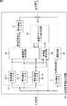
図1は、入力信号としての復号後の低域のパワースペクトルと、推定した高域の周波数包絡の一例を示している。 FIG. 1 shows an example of a low-frequency power spectrum after decoding as an input signal and an estimated high-frequency envelope.
図1において、縦軸は、パワーを対数で示し、横軸は、周波数を示している。 In FIG. 1, the vertical axis indicates power in logarithm, and the horizontal axis indicates frequency.
装置は、入力信号に関する符号化方式の種類や、サンプリングレート、ビットレート等の情報(以下、サイド情報と称する)から、高域の信号成分の低域端の帯域(以下、拡大開始帯域と称する)を決定する。次に、装置は、低域の信号成分としての入力信号を複数のサブバンド信号に分割する。装置は、分割後の複数のサブバンド信号、すなわち、拡大開始帯域より低域側(以下、単に、低域側と称する)の複数のサブバンド信号のそれぞれのパワーの、時間方向についてのグループ毎の平均(以下、グループパワーと称する)を求める。図1に示されるように、装置は、低域側の複数のサブバンドの信号のそれぞれのグループパワーの平均をパワーとし、かつ、拡大開始帯域の下端の周波数を周波数とする点を起点とする。装置は、その起点を通る所定の傾きの一次直線を、拡大開始帯域より高域側(以下、単に、高域側と称する)の周波数包絡として推定する。なお、起点のパワー方向についての位置は、ユーザにより調整可能とされる。装置は、高域側の複数のサブバンドの信号のそれぞれを、推定した高域側の周波数包絡となるように、低域側の複数のサブバンドの信号から生成する。装置は、生成した高域側の複数のサブバンドの信号を加算して高域の信号成分とし、さらに、低域の信号成分を加算して出力する。これにより、周波数帯域の拡大後の音楽信号は、本来の音楽信号により近いものとなる。したがって、より高音質の音楽信号を再生することが可能となる。 The apparatus determines the low band end band (hereinafter referred to as the expansion start band) of the high frequency signal component from the information (hereinafter referred to as side information) such as the type of the encoding method relating to the input signal, the sampling rate, and the bit rate. ). Next, the apparatus divides the input signal as a low-frequency signal component into a plurality of subband signals. For each group in the time direction, the power of each of a plurality of subband signals after division, that is, a plurality of subband signals lower than the expansion start band (hereinafter simply referred to as a low band side). Is obtained (hereinafter referred to as group power). As shown in FIG. 1, the apparatus starts from a point where the average of the group powers of a plurality of subband signals on the low frequency side is the power and the frequency at the lower end of the expansion start band is the frequency. . The apparatus estimates a linear line having a predetermined slope passing through the starting point as a frequency envelope on the high frequency side (hereinafter simply referred to as the high frequency side) from the expansion start band. The position of the starting point in the power direction can be adjusted by the user. The apparatus generates each of a plurality of subband signals on the high frequency side from the signals of the plurality of subbands on the low frequency side so that the estimated frequency envelope on the high frequency side is obtained. The apparatus adds a plurality of high-frequency side subband signals generated to form a high-frequency signal component, and further adds and outputs a low-frequency signal component. As a result, the music signal after the expansion of the frequency band becomes closer to the original music signal. Therefore, it is possible to reproduce a music signal with higher sound quality.
上述した特許文献1の帯域拡大手法は、様々な高域削除符号化手法や様々なビットレートの符号化データについて、その符号化データの復号後の音楽信号についての周波数帯域を拡大することができるという特長を有している。
The above-described band expansion method of
しかしながら、特許文献1の帯域拡大手法は、推定した高域側の周波数包絡が所定の傾きの一次直線となっている点で、すなわち、周波数包絡の形状が固定となっている点で改善の余地がある。
However, the band expansion method of
すなわち、音楽信号のパワースペクトルは様々な形状を持っており、音楽信号の種類によっては、特許文献1の帯域拡大手法により推定される高域側の周波数包絡から大きく外れる場合も少なくない。
That is, the power spectrum of the music signal has various shapes, and depending on the type of the music signal, there are many cases where the frequency envelope deviates significantly from the high frequency side frequency envelope estimated by the band expansion method of
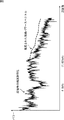
図2は、例えば、ドラムを1度強く叩いたときのような、時間的に急激な変化を伴うアタック性の音楽信号(アタック性音楽信号)の本来のパワースペクトルの一例を示している。 FIG. 2 shows an example of the original power spectrum of an attack music signal (attack music signal) accompanied by a rapid change in time, such as when the drum is struck once.
なお、図2には、特許文献1の帯域拡大手法により、アタック性音楽信号のうちの低域側の信号成分を入力信号として、その入力信号から推定した高域側の周波数包絡についても併せて示されている。
FIG. 2 also shows the frequency envelope on the high frequency side estimated from the input signal using the low frequency signal component of the attack music signal as the input signal by the band expansion method of
図2に示されるように、アタック性音楽信号の本来の高域側のパワースペクトルは、ほぼ平坦となっている。 As shown in FIG. 2, the original high-frequency power spectrum of the attack music signal is substantially flat.
これに対して、推定した高域側の周波数包絡は、所定の負の傾きを有しており、起点で、本来のパワースペクトルに近いパワーに調節したとしても、周波数が高くなるにつれて本来のパワースペクトルとの差が大きくなる。 On the other hand, the estimated frequency envelope on the high frequency side has a predetermined negative slope, and even if the power is adjusted to be close to the original power spectrum at the starting point, the original power is increased as the frequency is increased. The difference from the spectrum increases.
このように、特許文献1の帯域拡大手法では、推定した高域側の周波数包絡は、本来の高域側の周波数包絡を高精度に再現することができない。その結果、周波数帯域の拡大後の音楽信号から音を生成して出力すると、聴感上、原音よりも音の明瞭性が失われていることがあった。
As described above, in the band expansion method of
また、前述のHE-AAC等の高域特徴符号化手法では、符号化される高域の信号成分の特徴的な情報として、高域側の周波数包絡が用いられるが、復号側で本来の高域側の周波数包絡を高精度に再現することが求められる。 Further, in the above-described high-frequency feature coding method such as HE-AAC, the frequency envelope on the high frequency side is used as characteristic information of the high frequency signal component to be encoded. It is required to reproduce the frequency envelope on the band side with high accuracy.
本発明は、このような状況に鑑みてなされたものであり、周波数帯域の拡大により、音楽信号をより高音質に再生することができるようにするものである。 The present invention has been made in view of such a situation, and enables music signals to be reproduced with higher sound quality by expanding the frequency band.
本発明の第1の側面の信号処理装置は、処理対象区間を、高域信号の生成に用いる同じ係数が選択されたフレームからなる同じ長さのいくつかの区間に分割したときの前記区間の長さを示す情報、前記区間の境界位置の前後で、選択された前記係数が変化したかを示す情報、および前記区間のフレームで選択された前記係数を得るための係数情報からなるデータと、低域符号化データとに、入力された符号化データを非多重化する非多重化部と、前記低域符号化データを復号して低域信号を生成する低域復号部と、前記係数情報に基づいて、処理対象フレームの前記係数を選択する選択部と、前記処理対象フレームの前記低域信号を構成する各サブバンドの低域サブバンド信号の低域サブバンドパワーと、選択された前記係数とに基づいて、前記処理対象フレームの前記高域信号を構成する各サブバンドの高域サブバンド信号の高域サブバンドパワーを算出する高域サブバンドパワー算出部と、前記高域サブバンドパワーと前記低域サブバンド信号とに基づいて、前記処理対象フレームの前記高域信号を生成する高域信号生成部とを備える。 In the signal processing device according to the first aspect of the present invention, the processing target section is divided into several sections having the same length composed of frames in which the same coefficient used for generating the high frequency signal is selected . Data consisting of information indicating length, information indicating whether the selected coefficient has changed before and after the boundary position of the section , and coefficient information for obtaining the coefficient selected in the frame of the section; A demultiplexing unit that demultiplexes input encoded data into lowband encoded data; a lowband decoding unit that decodes the lowband encoded data to generate a lowband signal; and the coefficient information The selection unit for selecting the coefficient of the processing target frame, the low frequency subband power of the low frequency subband signal of each subband constituting the low frequency signal of the processing target frame, and the selected Based on the coefficient and A high-frequency sub-band power calculation unit for calculating a high-frequency sub-band power of a high-frequency sub-band signal of each sub-band constituting the high-frequency signal of the processing target frame, the high-frequency sub-band power and the low-frequency sub-band A high-frequency signal generation unit configured to generate the high-frequency signal of the processing target frame based on a band signal.
連続するいくつかの前記区間で同じ前記係数が選択された場合、前記データには、前記連続するいくつかの前記区間で選択された前記係数を得るための1つの前記係数情報が含まれているようにすることができる。 When the same coefficient is selected in several consecutive sections, the data includes one coefficient information for obtaining the coefficient selected in the several consecutive sections. Can be.
異なる前記係数が選択された、互いに隣接するフレームの位置が境界位置となるように前記処理対象区間をいくつかの区間に分割したときの区間の長さを示す情報と、前記係数情報とを前記データとする第1の方式と、前記処理対象区間を前記同じ長さのいくつかの区間に分割したときの区間の長さを示す情報、区間の境界位置の前後で、選択された前記係数が変化したかを示す情報、および前記係数情報を前記データとする第2の方式とのうち、よりデータ量が少ない方式で前記処理対象区間ごとに前記データが生成され、前記データには、前記第1の方式または前記第2の方式の何れの方式のデータであるかを示す情報がさらに含まれているようにすることができる。 Said different coefficients are selected, and information indicating the length of a section when divided into several sections of the processing target section as the position of the frames adjacent to each other at the boundary position, and the coefficient information the The first method for data, the information indicating the length of the section when the process target section is divided into several sections of the same length, the coefficients selected before and after the boundary position of the section are The data is generated for each processing target section by a method with a smaller amount of data among the information indicating whether the data has changed and the second method using the coefficient information as the data . Information indicating which data of the first method or the second method can be further included.
前記データには、最初のフレームの前記係数と、前記最初のフレームの直前のフレームの前記係数とが同じであるかを示す再利用情報がさらに含まれ、前記データに、前記係数が同じである旨の前記再利用情報が含まれる場合、前記データには、前記処理対象区間の最初の前記区間の前記係数情報が含まれていないようにすることができる。 The data further includes reuse information indicating whether the coefficient of the first frame is the same as the coefficient of the frame immediately before the first frame, and the data has the same coefficient. if it contains the recycling information to the effect that, in the data may be so that it does not contain the factor information for the first of said sections of the processing target section.
前記係数情報が再利用されるモードが指定された場合、前記データには前記再利用情報が含まれ、前記係数情報の再利用が禁止されるモードが指定された場合、前記データには、前記再利用情報が含まれないようにすることができる。 When a mode in which the coefficient information is reused is designated, the data includes the reuse information. When a mode in which the reuse of the coefficient information is prohibited is designated, the data includes the data It is possible to prevent reuse information from being included.
本発明の第1の側面の信号処理方法またはプログラムは、処理対象区間を、高域信号の生成に用いる同じ係数が選択されたフレームからなる同じ長さのいくつかの区間に分割したときの前記区間の長さを示す情報、前記区間の境界位置の前後で、選択された前記係数が変化したかを示す情報、および前記区間のフレームで選択された前記係数を得るための係数情報からなるデータと、低域符号化データとに、入力された符号化データを非多重化し、前記低域符号化データを復号して低域信号を生成し、前記係数情報に基づいて、処理対象フレームの前記係数を選択し、前記処理対象フレームの前記低域信号を構成する各サブバンドの低域サブバンド信号の低域サブバンドパワーと、選択された前記係数とに基づいて、前記処理対象フレームの前記高域信号を構成する各サブバンドの高域サブバンド信号の高域サブバンドパワーを算出し、前記高域サブバンドパワーと前記低域サブバンド信号とに基づいて、前記処理対象フレームの前記高域信号を生成するステップを含む。 In the signal processing method or program according to the first aspect of the present invention, the processing target section is divided into several sections having the same length composed of frames in which the same coefficient used for generating the high frequency signal is selected. Data consisting of information indicating the length of the section, information indicating whether the selected coefficient has changed before and after the boundary position of the section , and coefficient information for obtaining the coefficient selected in the frame of the section And de-multiplexing the input encoded data into the low frequency encoded data, decoding the low frequency encoded data to generate a low frequency signal, and based on the coefficient information, A coefficient is selected, and based on the low frequency subband power of the low frequency subband signal of each subband constituting the low frequency signal of the processing target frame and the selected coefficient, the processing target frame Calculating a high frequency sub-band power of a high frequency sub-band signal of each sub-band constituting the high frequency signal, and based on the high frequency sub-band power and the low frequency sub-band signal, the processing frame of the processing target frame Generating a high frequency signal.
本発明の第1の側面においては、処理対象区間を、高域信号の生成に用いる同じ係数が選択されたフレームからなる同じ長さのいくつかの区間に分割したときの前記区間の長さを示す情報、前記区間の境界位置の前後で、選択された前記係数が変化したかを示す情報、および前記区間のフレームで選択された前記係数を得るための係数情報からなるデータと、低域符号化データとに、入力された符号化データが非多重化され、前記低域符号化データが復号されて低域信号が生成され、前記係数情報に基づいて、処理対象フレームの前記係数が選択され、前記処理対象フレームの前記低域信号を構成する各サブバンドの低域サブバンド信号の低域サブバンドパワーと、選択された前記係数とに基づいて、前記処理対象フレームの前記高域信号を構成する各サブバンドの高域サブバンド信号の高域サブバンドパワーが算出され、前記高域サブバンドパワーと前記低域サブバンド信号とに基づいて、前記処理対象フレームの前記高域信号が生成される。 In the first aspect of the present invention, the length of the section when the section to be processed is divided into several sections having the same length composed of frames in which the same coefficient used for generating the high frequency signal is selected. Data including information indicating, information indicating whether the selected coefficient has changed before and after the boundary position of the section , and coefficient information for obtaining the coefficient selected in the frame of the section, and a low-frequency code The encoded data input is demultiplexed with the encoded data, the low-frequency encoded data is decoded to generate a low-frequency signal, and the coefficient of the processing target frame is selected based on the coefficient information. , Based on the low-frequency subband power of the low-frequency subband signal of each subband constituting the low-frequency signal of the processing target frame and the selected coefficient, the high-frequency signal of the processing target frame The high frequency subband power of the high frequency subband signal of each subband is calculated, and the high frequency signal of the processing target frame is generated based on the high frequency subband power and the low frequency subband signal. Is done.
本発明の第2の側面の信号処理装置は、入力信号の低域側の複数のサブバンドの低域サブバンド信号と、前記入力信号の高域側の複数のサブバンドの高域サブバンド信号とを生成するサブバンド分割部と、前記低域サブバンド信号の低域サブバンドパワーと所定の係数とに基づいて、前記高域サブバンド信号のパワーの推定値である擬似高域サブバンドパワーを算出する擬似高域サブバンドパワー算出部と、前記高域サブバンド信号の高域サブバンドパワーと、前記擬似高域サブバンドパワーとを比較して、前記入力信号のフレームごとに前記係数を選択する選択部と、処理対象区間を、同じ前記係数が選択されたフレームからなる同じ長さのいくつかの区間に分割したときの前記区間の長さを示す情報、前記区間の境界位置の前後で、選択された前記係数が変化したかを示す情報、および前記区間のフレームで選択された前記係数を得るための係数情報からなるデータを生成する生成部とを備える。 The signal processing device according to the second aspect of the present invention includes a low-frequency sub-band signal of a plurality of sub-bands on a low-frequency side of an input signal and a high-frequency sub-band signal of a plurality of sub-bands on a high-frequency side of the input signal. And a pseudo high band sub-band power that is an estimate of the power of the high band sub-band signal based on the low band sub-band power of the low band sub-band signal and a predetermined coefficient A pseudo high band sub-band power calculation unit that calculates the high band sub-band power of the high band sub-band signal and the pseudo high band sub-band power, and the coefficient for each frame of the input signal Information indicating the length of the section when the selection section to be selected and the section to be processed are divided into several sections of the same length composed of frames with the same coefficient selected , before and after the boundary position of the section And select Information indicating whether the coefficient has changed that, and a generation unit for generating data comprising a coefficient information for obtaining the coefficient selected by the frame of the section.
前記生成部には、異なる前記係数が選択された、互いに隣接するフレームの位置が境界位置となるように前記処理対象区間をいくつかの区間に分割したときの区間の長さを示す情報と、前記係数情報とを前記データとする第1の方式と、前記処理対象区間を前記同じ長さのいくつかの区間に分割したときの区間の長さを示す情報、区間の境界位置の前後で、選択された前記係数が変化したかを示す情報、および前記係数情報を前記データとする第2の方式とのうち、よりデータ量が少ない方式で前記処理対象区間ごとに、前記データを生成させることができる。 The generation unit, information indicating the lengths of said different coefficients are selected, when divided into several sections of the processing target section as the position of the frames adjacent to each other at the boundary position interval, The first method using the coefficient information as the data, information indicating the length of the section when the processing target section is divided into several sections of the same length, before and after the boundary position of the section, Generating the data for each of the processing target sections in a method having a smaller amount of data among the information indicating whether the selected coefficient has changed and the second method using the coefficient information as the data. Can do.
前記生成部には、最初のフレームの前記係数と、前記最初のフレームの直前のフレームの前記係数とが同じであるかを示す再利用情報がさらに含まれる前記データを生成させ、前記係数が同じである旨の前記再利用情報が前記データに含まれる場合、前記処理対象区間の最初の前記区間の前記係数情報が含まれない前記データが生成されるようにすることができる。 The generation unit generates the data further including reuse information indicating whether the coefficient of the first frame and the coefficient of the frame immediately before the first frame are the same, and the coefficients are the same If the re-use information indicating that the is included in the data, the first of the data to which the not contain factor information of the section of the processing target section can be made to be generated.
本発明の第2の側面の信号処理方法またはプログラムは、入力信号の低域側の複数のサブバンドの低域サブバンド信号と、前記入力信号の高域側の複数のサブバンドの高域サブバンド信号とを生成し、前記低域サブバンド信号の低域サブバンドパワーと所定の係数とに基づいて、前記高域サブバンド信号のパワーの推定値である擬似高域サブバンドパワーを算出し、前記高域サブバンド信号の高域サブバンドパワーと、前記擬似高域サブバンドパワーとを比較して、前記入力信号のフレームごとに前記係数を選択し、処理対象区間を、同じ前記係数が選択されたフレームからなる同じ長さのいくつかの区間に分割したときの前記区間の長さを示す情報、前記区間の境界位置の前後で、選択された前記係数が変化したかを示す情報、および前記区間のフレームで選択された前記係数を得るための係数情報からなるデータを生成するステップを含む。 The signal processing method or program according to the second aspect of the present invention includes a low frequency subband signal of a plurality of subbands on a low frequency side of an input signal and a high frequency subband of a plurality of subbands on the high frequency side of the input signal. And a pseudo high band sub-band power that is an estimate of the power of the high band sub-band signal is calculated based on the low band sub-band power of the low band sub-band signal and a predetermined coefficient. , and high frequency sub-band power of the high frequency sub-band signals, by comparing the pseudo high frequency sub-band power, select the coefficients for each frame of the input signal, the processing target section, the same said coefficients Information indicating the length of the section when divided into several sections of the same length composed of selected frames, information indicating whether the selected coefficient has changed before and after the boundary position of the section; and the Comprising the step of generating a data consisting of coefficient information for obtaining the coefficient selected by the frames between.
本発明の第2の側面においては、入力信号の低域側の複数のサブバンドの低域サブバンド信号と、前記入力信号の高域側の複数のサブバンドの高域サブバンド信号とが生成され、前記低域サブバンド信号の低域サブバンドパワーと所定の係数とに基づいて、前記高域サブバンド信号のパワーの推定値である擬似高域サブバンドパワーが算出され、前記高域サブバンド信号の高域サブバンドパワーと、前記擬似高域サブバンドパワーとが比較されて、前記入力信号のフレームごとに前記係数が選択され、処理対象区間を、同じ前記係数が選択されたフレームからなる同じ長さのいくつかの区間に分割したときの前記区間の長さを示す情報、前記区間の境界位置の前後で、選択された前記係数が変化したかを示す情報、および前記区間のフレームで選択された前記係数を得るための係数情報からなるデータが生成される。 In the second aspect of the present invention, a low frequency subband signal of a plurality of subbands on the low frequency side of the input signal and a high frequency subband signal of a plurality of subbands on the high frequency side of the input signal are generated. Based on the low frequency subband power of the low frequency subband signal and a predetermined coefficient, a pseudo high frequency subband power that is an estimated value of the power of the high frequency subband signal is calculated, and the high frequency subband power is calculated. The high frequency sub-band power of the band signal is compared with the pseudo high frequency sub-band power, the coefficient is selected for each frame of the input signal, and the processing target section is selected from the frame where the same coefficient is selected. becomes information indicating the length of the interval of time divided into several sections of equal length, before and after the boundary position of the section, the information indicating whether the coefficient selected is changed, and the frame of the section Data is generated consisting of coefficient information for obtaining a selected said coefficients.
本発明の第3の側面の復号装置は、処理対象区間を、高域信号の生成に用いる同じ係数が選択されたフレームからなる同じ長さのいくつかの区間に分割したときの前記区間の長さを示す情報、前記区間の境界位置の前後で、選択された前記係数が変化したかを示す情報、および前記区間のフレームで選択された前記係数を得るための係数情報からなるデータと、低域符号化データとに、入力された符号化データを非多重化する非多重化部と、前記低域符号化データを復号して低域信号を生成する低域復号部と、前記係数情報に基づいて、処理対象フレームの前記係数を選択する選択部と、前記処理対象フレームの前記低域信号を構成する各サブバンドの低域サブバンド信号の低域サブバンドパワーと、選択された前記係数とに基づいて、前記処理対象フレームの前記高域信号を構成する各サブバンドの高域サブバンド信号の高域サブバンドパワーを算出する高域サブバンドパワー算出部と、前記高域サブバンドパワーと前記低域サブバンド信号とに基づいて、前記処理対象フレームの前記高域信号を生成する高域信号生成部と、前記低域信号と前記高域信号とを合成して、出力信号を生成する合成部とを備える。 The decoding device according to the third aspect of the present invention provides the length of the section when the section to be processed is divided into several sections having the same length composed of frames in which the same coefficient used for generating the high frequency signal is selected. Data including information indicating the length, information indicating whether the selected coefficient has changed before and after the boundary position of the section , and data including coefficient information for obtaining the coefficient selected in the frame of the section; A demultiplexing unit that demultiplexes the input encoded data into the region encoded data, a lowband decoding unit that generates a lowband signal by decoding the lowband encoded data, and the coefficient information Based on the selection unit for selecting the coefficient of the processing target frame, the low frequency subband power of the low frequency subband signal of each subband constituting the low frequency signal of the processing target frame, and the selected coefficient And based on A high-frequency sub-band power calculating unit for calculating a high-frequency sub-band power of a high-frequency sub-band signal of each sub-band constituting the high-frequency signal of the target frame; and the high-frequency sub-band power and the low-frequency sub-band A high-frequency signal generation unit that generates the high-frequency signal of the processing target frame based on a signal, and a synthesis unit that combines the low-frequency signal and the high-frequency signal to generate an output signal. .
本発明の第3の側面の復号方法は、処理対象区間を、高域信号の生成に用いる同じ係数が選択されたフレームからなる同じ長さのいくつかの区間に分割したときの前記区間の長さを示す情報、前記区間の境界位置の前後で、選択された前記係数が変化したかを示す情報、および前記区間のフレームで選択された前記係数を得るための係数情報からなるデータと、低域符号化データとに、入力された符号化データを非多重化し、前記低域符号化データを復号して低域信号を生成し、前記係数情報に基づいて、処理対象フレームの前記係数を選択し、前記処理対象フレームの前記低域信号を構成する各サブバンドの低域サブバンド信号の低域サブバンドパワーと、選択された前記係数とに基づいて、前記処理対象フレームの前記高域信号を構成する各サブバンドの高域サブバンド信号の高域サブバンドパワーを算出し、前記高域サブバンドパワーと前記低域サブバンド信号とに基づいて、前記処理対象フレームの前記高域信号を生成し、前記低域信号と前記高域信号とを合成して、出力信号を生成するステップを含む。 In the decoding method according to the third aspect of the present invention, the length of the section when the section to be processed is divided into several sections having the same length composed of frames in which the same coefficient used for generating the high frequency signal is selected. Data including information indicating the length, information indicating whether the selected coefficient has changed before and after the boundary position of the section , and data including coefficient information for obtaining the coefficient selected in the frame of the section; The input encoded data is demultiplexed with the band encoded data, the low band encoded data is decoded to generate a low band signal, and the coefficient of the processing target frame is selected based on the coefficient information And the high frequency signal of the processing target frame based on the low frequency subband power of the low frequency subband signal of each subband constituting the low frequency signal of the processing target frame and the selected coefficient. Configure Calculating the high frequency sub-band power of the high frequency sub-band signal of each sub-band, and generating the high frequency signal of the processing target frame based on the high frequency sub-band power and the low frequency sub-band signal, Synthesizing the low-frequency signal and the high-frequency signal to generate an output signal.
本発明の第3の側面においては、処理対象区間を、高域信号の生成に用いる同じ係数が選択されたフレームからなる同じ長さのいくつかの区間に分割したときの前記区間の長さを示す情報、前記区間の境界位置の前後で、選択された前記係数が変化したかを示す情報、および前記区間のフレームで選択された前記係数を得るための係数情報からなるデータと、低域符号化データとに、入力された符号化データが非多重化され、前記低域符号化データが復号されて低域信号が生成され、前記係数情報に基づいて、処理対象フレームの前記係数が選択され、前記処理対象フレームの前記低域信号を構成する各サブバンドの低域サブバンド信号の低域サブバンドパワーと、選択された前記係数とに基づいて、前記処理対象フレームの前記高域信号を構成する各サブバンドの高域サブバンド信号の高域サブバンドパワーが算出され、前記高域サブバンドパワーと前記低域サブバンド信号とに基づいて、前記処理対象フレームの前記高域信号が生成され、前記低域信号と前記高域信号とが合成されて、出力信号が生成される。 In the third aspect of the present invention, the length of the section when the section to be processed is divided into several sections having the same length composed of frames in which the same coefficient used for generating the high frequency signal is selected. Data including information indicating, information indicating whether the selected coefficient has changed before and after the boundary position of the section , and coefficient information for obtaining the coefficient selected in the frame of the section, and a low-frequency code The encoded data input is demultiplexed with the encoded data, the low-frequency encoded data is decoded to generate a low-frequency signal, and the coefficient of the processing target frame is selected based on the coefficient information. , Based on the low-frequency subband power of the low-frequency subband signal of each subband constituting the low-frequency signal of the processing target frame and the selected coefficient, the high-frequency signal of the processing target frame The high frequency subband power of the high frequency subband signal of each subband is calculated, and the high frequency signal of the processing target frame is generated based on the high frequency subband power and the low frequency subband signal. Then, the low frequency signal and the high frequency signal are combined to generate an output signal.
本発明の第4の側面の符号化装置は、入力信号の低域側の複数のサブバンドの低域サブバンド信号と、前記入力信号の高域側の複数のサブバンドの高域サブバンド信号とを生成するサブバンド分割部と、前記低域サブバンド信号の低域サブバンドパワーと所定の係数とに基づいて、前記高域サブバンド信号のパワーの推定値である擬似高域サブバンドパワーを算出する擬似高域サブバンドパワー算出部と、前記高域サブバンド信号の高域サブバンドパワーと、前記擬似高域サブバンドパワーとを比較して、前記入力信号のフレームごとに前記係数を選択する選択部と、処理対象区間を、同じ前記係数が選択されたフレームからなる同じ長さのいくつかの区間に分割したときの前記区間の長さを示す情報、前記区間の境界位置の前後で、選択された前記係数が変化したかを示す情報、および前記区間のフレームで選択された前記係数を得るための係数情報を符号化して高域符号化データを生成する高域符号化部と、前記入力信号の低域信号を符号化し、低域符号化データを生成する低域符号化部と、前記低域符号化データと前記高域符号化データとを多重化して出力符号列を生成する多重化部とを備える。 The encoding device according to the fourth aspect of the present invention provides a low frequency subband signal of a plurality of subbands on the low frequency side of an input signal and a high frequency subband signal of a plurality of subbands on the high frequency side of the input signal. And a pseudo high band sub-band power that is an estimate of the power of the high band sub-band signal based on the low band sub-band power of the low band sub-band signal and a predetermined coefficient A pseudo high band sub-band power calculation unit that calculates the high band sub-band power of the high band sub-band signal and the pseudo high band sub-band power, and the coefficient for each frame of the input signal Information indicating the length of the section when the selection section to be selected and the section to be processed are divided into several sections of the same length composed of frames with the same coefficient selected , before and after the boundary position of the section And selected Said information indicating whether the coefficient is changed, and a high frequency encoding unit for generating a high frequency encoded data coefficient information for obtaining the coefficient selected by the frame of the section encodes the input signal A low frequency encoding unit that encodes a low frequency signal and generates low frequency encoded data, and a multiplexing unit that multiplexes the low frequency encoded data and the high frequency encoded data to generate an output code string With.
本発明の第4の側面の符号化方法は、入力信号の低域側の複数のサブバンドの低域サブバンド信号と、前記入力信号の高域側の複数のサブバンドの高域サブバンド信号とを生成し、前記低域サブバンド信号の低域サブバンドパワーと所定の係数とに基づいて、前記高域サブバンド信号のパワーの推定値である擬似高域サブバンドパワーを算出し、前記高域サブバンド信号の高域サブバンドパワーと、前記擬似高域サブバンドパワーとを比較して、前記入力信号のフレームごとに前記係数を選択し、処理対象区間を、同じ前記係数が選択されたフレームからなる同じ長さのいくつかの区間に分割したときの前記区間の長さを示す情報、前記区間の境界位置の前後で、選択された前記係数が変化したかを示す情報、および前記区間のフレームで選択された前記係数を得るための係数情報を符号化して高域符号化データを生成し、前記入力信号の低域信号を符号化し、低域符号化データを生成し、前記低域符号化データと前記高域符号化データとを多重化して出力符号列を生成するステップを含む。 The encoding method according to the fourth aspect of the present invention includes a low-frequency subband signal of a plurality of subbands on a low frequency side of an input signal and a high frequency subband signal of a plurality of subbands on a high frequency side of the input signal. Generating a pseudo high band sub-band power that is an estimated value of the power of the high band sub-band signal based on the low band sub-band power of the low band sub-band signal and a predetermined coefficient, The high frequency sub-band power of the high frequency sub-band signal is compared with the pseudo high frequency sub-band power, the coefficient is selected for each frame of the input signal, and the same coefficient is selected as the processing target section. Information indicating the length of the section when divided into several sections of the same length composed of frames, information indicating whether the selected coefficient has changed before and after the boundary position of the section, and Select by section frame The coefficient information for obtaining the coefficients by encoding to generate a high frequency encoding data, the low frequency signal of the input signal is encoded to generate a low-frequency encoded data, and the low frequency encoded data And a step of generating an output code string by multiplexing the high frequency encoded data.
本発明の第4の側面においては、入力信号の低域側の複数のサブバンドの低域サブバンド信号と、前記入力信号の高域側の複数のサブバンドの高域サブバンド信号とが生成され、前記低域サブバンド信号の低域サブバンドパワーと所定の係数とに基づいて、前記高域サブバンド信号のパワーの推定値である擬似高域サブバンドパワーが算出され、前記高域サブバンド信号の高域サブバンドパワーと、前記擬似高域サブバンドパワーとが比較されて、前記入力信号のフレームごとに前記係数が選択され、処理対象区間を、同じ前記係数が選択されたフレームからなる同じ長さのいくつかの区間に分割したときの前記区間の長さを示す情報、前記区間の境界位置の前後で、選択された前記係数が変化したかを示す情報、および前記区間のフレームで選択された前記係数を得るための係数情報が符号化されて高域符号化データが生成され、前記入力信号の低域信号が符号化され、低域符号化データが生成され、前記低域符号化データと前記高域符号化データとが多重化されて出力符号列が生成される。 In the fourth aspect of the present invention, low frequency subband signals of a plurality of subbands on the low frequency side of the input signal and high frequency subband signals of a plurality of subbands on the high frequency side of the input signal are generated. Based on the low frequency subband power of the low frequency subband signal and a predetermined coefficient, a pseudo high frequency subband power that is an estimated value of the power of the high frequency subband signal is calculated, and the high frequency subband power is calculated. The high frequency sub-band power of the band signal is compared with the pseudo high frequency sub-band power, the coefficient is selected for each frame of the input signal, and the processing target section is selected from the frame where the same coefficient is selected. becomes information indicating the length of the interval of time divided into several sections of equal length, before and after the boundary position of the section, the information indicating whether the coefficient selected is changed, and the frame of the section Coefficient information for obtaining the selected the coefficients are in the high frequency encoded data generated encoded low frequency signal of the input signal is encoded, the low frequency encoded data is generated, the low-frequency encoding The encoded data and the high frequency encoded data are multiplexed to generate an output code string.
本発明の第1乃至第4の側面によれば、周波数帯域の拡大により、音楽信号をより高音質に再生することができる。 According to the first to fourth aspects of the present invention, music signals can be reproduced with higher sound quality by expanding the frequency band.
以下、本発明の実施の形態について図を参照して説明する。なお、説明は以下の順序で行う。
1.第1の実施の形態(周波数帯域拡大装置に本発明を適用した場合)
2.第2の実施の形態(符号化装置および復号装置に本発明を適用した場合)
3.第3の実施の形態(係数インデックスを高域符号化データに含める場合)
4.第4の実施の形態(係数インデックスと擬似高域サブバンドパワー差分を高域符号化データに含める場合)
5.第5の実施の形態(評価値を用いて係数インデックスを選択する場合)
6.第6の実施の形態(係数の一部を共通にする場合)
7.第7の実施の形態(可変長方式で時間方向に係数インデックス列の符号量を削減する場合)
8.第8の実施の形態(固定長方式で時間方向に係数インデックス列の符号量を削減する場合)
9.第9の実施の形態(可変長方式または固定長方式の何れかを選択する場合)
10.第10の実施の形態(可変長方式で情報の再利用を行なう場合)
11.第11の実施の形態(固定長方式で情報の再利用を行なう場合)
Hereinafter, embodiments of the present invention will be described with reference to the drawings. The description will be given in the following order.
1. First embodiment (when the present invention is applied to a frequency band expansion device)
2. Second embodiment (when the present invention is applied to an encoding device and a decoding device)
3. Third embodiment (when a coefficient index is included in high frequency encoded data)
4). Fourth embodiment (when a coefficient index and a pseudo high band sub-band power difference are included in high band encoded data)
5. Fifth embodiment (when a coefficient index is selected using an evaluation value)
6). Sixth embodiment (when some of the coefficients are shared)
7). Seventh embodiment (when the code amount of the coefficient index sequence is reduced in the time direction by the variable length method)
8). Eighth Embodiment (When the code amount of the coefficient index sequence is reduced in the time direction by the fixed length method)
9. Ninth embodiment (when selecting either the variable length method or the fixed length method)
10. Tenth Embodiment (When Reusing Information in Variable Length Method)
11. Eleventh embodiment (when information is reused in a fixed-length method)
<1.第1の実施の形態>
第1の実施の形態では、高域削除符号化手法で符号化データを復号することで得られる復号後の低域の信号成分に対して、周波数帯域を拡大させる処理(以下、周波数帯域拡大処理と称する)が施される。
<1. First Embodiment>
In the first embodiment, a process of expanding a frequency band (hereinafter referred to as a frequency band expansion process) with respect to a low-frequency signal component after decoding obtained by decoding encoded data using a high-frequency deletion encoding method. Is called).
[周波数帯域拡大装置の機能的構成例]
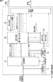
図3は、本発明を適用した周波数帯域拡大装置の機能的構成例を示している。
[Functional configuration example of frequency band expansion device]
FIG. 3 shows a functional configuration example of a frequency band expansion apparatus to which the present invention is applied.
周波数帯域拡大装置10は、復号後の低域の信号成分を入力信号として、その入力信号に対して、周波数帯域拡大処理を施し、その結果得られる周波数帯域拡大処理後の信号を出力信号として出力する。 The frequency band expansion device 10 uses the decoded low-frequency signal component as an input signal, performs frequency band expansion processing on the input signal, and outputs the resulting signal after frequency band expansion processing as an output signal To do.
周波数帯域拡大装置10は、低域通過フィルタ11、遅延回路12、帯域通過フィルタ13、特徴量算出回路14、高域サブバンドパワー推定回路15、高域信号生成回路16、高域通過フィルタ17、および信号加算器18から構成される。
The frequency band expansion apparatus 10 includes a low-
低域通過フィルタ11は、入力信号を所定の遮断周波数でフィルタリングし、フィルタリング後の信号として、低域の信号成分である低域信号成分を遅延回路12に供給する。
The low-
遅延回路12は、低域通過フィルタ11からの低域信号成分と後述する高域信号成分とを加算する際の同期をとるために、低域信号成分を、一定の遅延時間だけ遅延して信号加算器18に供給する。
The
帯域通過フィルタ13は、それぞれ異なる通過帯域を持つ帯域通過フィルタ13−1乃至13−Nから構成される。帯域通過フィルタ13−i(1≦i≦N)は、入力信号のうちの所定の通過帯域の信号を通過させ、複数のサブバンド信号のうちの1つとして、特徴量算出回路14および高域信号生成回路16に供給する。
The
特徴量算出回路14は、帯域通過フィルタ13からの複数のサブバンド信号と、入力信号との、少なくともいずれか一方を用いて、1または複数の特徴量を算出し、高域サブバンドパワー推定回路15に供給する。ここで、特徴量とは、入力信号の、信号としての特徴を表す情報である。
The feature
高域サブバンドパワー推定回路15は、特徴量算出回路14からの、1または複数の特徴量に基づいて、高域のサブバンド信号のパワーである高域サブバンドパワーの推定値を高域サブバンド毎に算出し、これらを高域信号生成回路16に供給する。
The high frequency sub-band
高域信号生成回路16は、帯域通過フィルタ13からの複数のサブバンド信号と、高域サブバンドパワー推定回路15からの複数の高域サブバンドパワーの推定値とに基づいて、高域の信号成分である高域信号成分を生成し、高域通過フィルタ17に供給する。
The high-frequency
高域通過フィルタ17は、高域信号生成回路16からの高域信号成分を、低域通過フィルタ11における遮断周波数に対応する遮断周波数でフィルタリングし、信号加算器18に供給する。
The high-
信号加算器18は、遅延回路12からの低域信号成分と、高域通過フィルタ17からの高域信号成分とを加算し、出力信号として出力する。
The
なお、図3の構成においては、サブバンド信号を取得するために帯域通過フィルタ13を適用するようにしたが、これに限らず、例えば、特許文献1に記載されているような帯域分割フィルタを適用するようにしてもよい。
In the configuration of FIG. 3, the
また同様に、図3の構成においては、サブバンド信号を合成するために信号加算器18を適用するようにしたが、これに限らず、例えば、特許文献1に記載されているような帯域合成フィルタを適用するようにしてもよい。
Similarly, in the configuration of FIG. 3, the
[周波数帯域拡大装置の周波数帯域拡大処理]
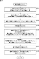
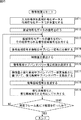
次に、図4のフローチャートを参照して、図3の周波数帯域拡大装置による周波数帯域拡大処理について説明する。
[Frequency band expansion processing of frequency band expansion device]
Next, frequency band expansion processing by the frequency band expansion device in FIG. 3 will be described with reference to the flowchart in FIG.
ステップS1において、低域通過フィルタ11は、入力信号を所定の遮断周波数でフィルタリングし、フィルタリング後の信号としての低域信号成分を遅延回路12に供給する。
In step S <b> 1, the low-
低域通過フィルタ11は、遮断周波数として任意の周波数を設定することが可能であるが、本実施の形態では、所定の帯域を後述する拡大開始帯域として、その拡大開始帯域の下端の周波数に対応して遮断周波数が設定される。したがって、低域通過フィルタ11は、フィルタリング後の信号として、拡大開始帯域より低域の信号成分である低域信号成分を、遅延回路12に供給する。
The low-
また、低域通過フィルタ11は、入力信号の高域削除符号化手法やビットレート等の符号化パラメータに応じて、最適な周波数を遮断周波数として設定することもできる。この符号化パラメータとしては、例えば、特許文献1の帯域拡大手法で採用されているサイド情報を利用することができる。
The low-
ステップS2において、遅延回路12は、低域通過フィルタ11からの低域信号成分を一定の遅延時間だけ遅延して信号加算器18に供給する。
In step S <b> 2, the
ステップS3において、帯域通過フィルタ13(帯域通過フィルタ13−1乃至13−N)は、入力信号を複数のサブバンド信号に分割し、分割後の複数のサブバンド信号のそれぞれを、特徴量算出回路14および高域信号生成回路16に供給する。なお、帯域通過フィルタ13による入力信号の分割の処理については、その詳細を後述する。
In step S3, the band-pass filter 13 (band-pass filters 13-1 to 13-N) divides the input signal into a plurality of subband signals, and each of the divided subband signals is a feature amount calculation circuit. 14 and the high-frequency
ステップS4において、特徴量算出回路14は、帯域通過フィルタ13からの複数のサブバンド信号と、入力信号との、少なくともいずれか一方を用いて、1または複数の特徴量を算出し、高域サブバンドパワー推定回路15に供給する。なお、特徴量算出回路14による特徴量の算出の処理については、その詳細を後述する。
In step S4, the feature
ステップS5において、高域サブバンドパワー推定回路15は、特徴量算出回路14からの、1または複数の特徴量に基づいて、複数の高域サブバンドパワーの推定値を算出し、高域信号生成回路16に供給する。なお、高域サブバンドパワー推定回路15による高域サブバンドパワーの推定値の算出の処理については、その詳細を後述する。
In step S5, the high frequency sub-band
ステップS6において、高域信号生成回路16は、帯域通過フィルタ13からの複数のサブバンド信号と、高域サブバンドパワー推定回路15からの複数の高域サブバンドパワーの推定値とに基づいて、高域信号成分を生成し、高域通過フィルタ17に供給する。ここでいう高域信号成分とは、拡大開始帯域より高域の信号成分である。なお、高域信号生成回路16による高域信号成分の生成の処理については、その詳細を後述する。
In step S6, the high frequency
ステップS7において、高域通過フィルタ17は、高域信号生成回路16からの高域信号成分をフィルタリングすることにより、高域信号成分に含まれる低域への折り返し成分等のノイズを除去し、その高域信号成分を信号加算器18に供給する。
In step S7, the high-
ステップS8において、信号加算器18は、遅延回路12からの低域信号成分と、高域通過フィルタ17からの高域信号成分とを加算し、出力信号として出力する。
In step S8, the
以上の処理によれば、復号後の低域の信号成分に対して、周波数帯域を拡大させることができる。 According to the above processing, the frequency band can be expanded with respect to the low-frequency signal component after decoding.
次に、図4のフローチャートのステップS3乃至S6のそれぞれの処理の詳細について説明する。 Next, the details of the processes of steps S3 to S6 in the flowchart of FIG. 4 will be described.
[帯域通過フィルタによる処理の詳細]
まず、図4のフローチャートのステップS3における帯域通過フィルタ13による処理の詳細について説明する。
[Details of processing by band pass filter]
First, details of the processing by the
なお、説明の便宜のため、以下においては、帯域通過フィルタ13の個数NをN=4とする。
For convenience of explanation, the number N of
例えば、入力信号のナイキスト周波数を16等分に分割することで得られる16個のサブバンドのうちの1つを拡大開始帯域とし、それら16個のサブバンドのうちの拡大開始帯域より低域の4個のサブバンドのそれぞれを、帯域通過フィルタ13−1乃至13−4の通過帯域のそれぞれとする。 For example, one of 16 subbands obtained by dividing the Nyquist frequency of the input signal into 16 equal parts is set as an expansion start band, and a lower band than the expansion start band of these 16 subbands. Each of the four subbands is assumed to be a passband of the bandpass filters 13-1 to 13-4.
図5は、帯域通過フィルタ13−1乃至13−4の各通過帯域それぞれの周波数軸上における配置を示している。 FIG. 5 shows the arrangement on the frequency axis of each pass band of the band pass filters 13-1 to 13-4.
図5に示されるように、拡大開始帯域より低域の周波数帯域(サブバンド)のうちの高域から1番目のサブバンドのインデックスをsb、2番目のサブバンドのインデックスをsb-1、I番目のサブバンドのインデックスをsb-(I-1)とすると、帯域通過フィルタ13−1乃至13−4それぞれは、拡大開始帯域より低域のサブバンドのうち、インデックスがsb乃至sb-3のサブバンドのそれぞれを、通過帯域として割り当てる。 As shown in FIG. 5, the index of the first subband from the high frequency band (subband) lower than the expansion start band is sb, the index of the second subband is sb-1, I Assuming that the index of the second subband is sb- (I-1), each of the bandpass filters 13-1 to 13-4 has an index of sb to sb-3 among the subbands lower than the expansion start band. Each subband is assigned as a passband.
なお、本実施の形態では、帯域通過フィルタ13−1乃至13−4の通過帯域のそれぞれは、入力信号のナイキスト周波数を16等分することで得られる16個のサブバンドのうちの所定の4個のそれぞれであるものとしたが、これに限らず、入力信号のナイキスト周波数を256等分することで得られる256個のサブバンドのうちの所定の4個のそれぞれであるようにしてもよい。また、帯域通過フィルタ13−1乃至13−4のそれぞれの帯域幅は、それぞれ異なっていてもよい。 In the present embodiment, each of the passbands of the bandpass filters 13-1 to 13-4 is a predetermined four of the 16 subbands obtained by dividing the Nyquist frequency of the input signal into 16 equal parts. However, the present invention is not limited to this, and each of the predetermined four of 256 subbands obtained by dividing the Nyquist frequency of the input signal into 256 equal parts may be used. . Further, the bandwidths of the bandpass filters 13-1 to 13-4 may be different from each other.
[特徴量算出回路による処理の詳細]
次に、図4のフローチャートのステップS4における特徴量算出回路14による処理の詳細について説明する。
[Details of processing by feature quantity calculation circuit]
Next, details of the processing by the feature
特徴量算出回路14は、帯域通過フィルタ13からの複数のサブバンド信号と、入力信号との、少なくともいずれか一方を用いて、高域サブバンドパワー推定回路15が高域サブバンドパワーの推定値を算出するために用いる、1または複数の特徴量を算出する。
The feature
より具体的には、特徴量算出回路14は、帯域通過フィルタ13からの4個のサブバンド信号から、サブバンド毎に、サブバンド信号のパワー(サブバンドパワー(以下、低域サブバンドパワーともいう))を特徴量として算出し、高域サブバンドパワー推定回路15に供給する。
More specifically, the feature
すなわち、特徴量算出回路14は、帯域通過フィルタ13から供給された、4個のサブバンド信号x(ib,n)から、ある所定の時間フレームJにおける低域サブバンドパワーpower(ib,J)を、以下の式(1)により求める。ここで、ibは、サブバンドのインデックス、nは離散時間のインデックスを表している。なお、1フレームのサンプル数をFSIZEとし、パワーはデシベルで表現されるものとする。
That is, the feature

このようにして、特徴量算出回路14によって求められた低域サブバンドパワーpower(ib,J)は、特徴量として高域サブバンドパワー推定回路15に供給される。
In this way, the low frequency sub-band power power (ib, J) obtained by the feature
[高域サブバンドパワー推定回路による処理の詳細]
次に、図4のフローチャートのステップS5における高域サブバンドパワー推定回路15による処理の詳細について説明する。
[Details of processing by high frequency sub-band power estimation circuit]
Next, details of the processing by the high frequency subband
高域サブバンドパワー推定回路15は、特徴量算出回路14から供給された4個のサブバンドパワーに基づいて、インデックスがsb+1であるサブバンド(拡大開始帯域)以降の、拡大しようとする帯域(周波数拡大帯域)のサブバンドパワー(高域サブバンドパワー)の推定値を算出する。
Based on the four subband powers supplied from the feature
すなわち、高域サブバンドパワー推定回路15は、周波数拡大帯域の最高域のサブバンドのインデックスをebとすると、インデックスがsb+1乃至ebであるサブバンドについて、(eb-sb)個のサブバンドパワーを推定する。
In other words, the high frequency subband
周波数拡大帯域における、インデックスがibであるサブバンドパワーの推定値powerest(ib,J)は、特徴量算出回路14から供給された4個のサブバンドパワーpower(ib,j)を用いて、例えば、以下の式(2)により表される。
The estimated value power est (ib, J) of the subband power whose index is ib in the frequency expansion band is obtained by using the four subband powers power (ib, j) supplied from the feature
ここで、式(2)において、係数Aib(kb),Bibは、サブバンドib毎に異なる値を持つ係数である。係数Aib(kb),Bibは、様々な入力信号に対して好適な値が得られるように適切に設定される係数とする。また、サブバンドsbの変更によって、係数Aib(kb),Bibも最適な値に変更される。なお、係数Aib(kb),Bibの導出については後述する。 Here, in Equation (2), the coefficients A ib (kb) and B ib are coefficients having different values for each subband ib. The coefficients A ib (kb) and B ib are coefficients that are appropriately set so as to obtain suitable values for various input signals. Further, the coefficients A ib (kb) and B ib are also changed to optimum values by changing the subband sb. Derivation of the coefficients A ib (kb) and B ib will be described later.
式(2)において、高域サブバンドパワーの推定値は、帯域通過フィルタ13からの複数のサブバンド信号それぞれのパワーを用いた1次線形結合により算出されているが、これに限らず、例えば、時間フレームJの前後数フレームの複数の低域サブバンドパワーの線形結合を用いて算出されるようにしてもよいし、非線形な関数を用いて算出されるようにしてもよい。
In the equation (2), the estimated value of the high frequency sub-band power is calculated by the linear linear combination using the power of each of the plurality of sub-band signals from the
このようにして、高域サブバンドパワー推定回路15によって算出された高域サブバンドパワーの推定値は、高域信号生成回路16に供給される。
In this way, the estimated value of the high frequency sub-band power calculated by the high frequency sub-band
[高域信号生成回路による処理の詳細]
次に、図4のフローチャートのステップS6における高域信号生成回路16による処理の詳細について説明する。
[Details of processing by high-frequency signal generation circuit]
Next, details of the processing by the high-frequency
高域信号生成回路16は、帯域通過フィルタ13から供給された複数のサブバンド信号から、上述の式(1)に基づいて、それぞれのサブバンドの低域サブバンドパワーpower(ib,J)を算出する。高域信号生成回路16は、算出した複数の低域サブバンドパワーpower(ib,J)と、高域サブバンドパワー推定回路15によって上述の式(2)に基づいて算出された高域サブバンドパワーの推定値powerest(ib,J)とを用いて、以下の式(3)によって、利得量G(ib,J)を求める。
The high-frequency
ここで、式(3)において、sbmap(ib)は、サブバンドibを写像先のサブバンドとした場合の写像元のサブバンドのインデックスを示しており、以下の式(4)で表わされる。 Here, in equation (3), sb map (ib) indicates the index of the mapping source subband when subband ib is the mapping target subband, and is represented by the following equation (4). .
なお、式(4)において、INT(a)は、値aの小数点以下を切り捨てる関数である。 In Expression (4), INT (a) is a function that truncates the value a after the decimal point.
次に、高域信号生成回路16は、以下の式(5)を用いて、式(3)によって求めた利得量G(ib,J)を帯域通過フィルタ13の出力に乗じることで、利得調整後のサブバンド信号x2(ib,n)を算出する。
Next, the high-frequency
さらに、高域信号生成回路16は、以下の式(6)によって、インデックスがsb-3であるサブバンドの下端の周波数に対応する周波数から、インデックスがsbであるサブバンドの上端の周波数に対応する周波数へコサイン変調を行うことで、利得調整後のサブバンド信号x2(ib,n)から、コサイン変換された利得調整後のサブバンド信号x3(ib,n)を算出する。
Further, the high frequency
なお、式(6)において、Πは円周率を表す。この式(6)は、利得調整後のサブバンド信号x2(ib,n)が、それぞれ4バンド分高域側の周波数にシフトされることを意味している。 In Equation (6), Π represents the circumference. This equation (6) means that the subband signal x2 (ib, n) after gain adjustment is shifted to the frequency on the high band side by 4 bands.
そして、高域信号生成回路16は、以下の式(7)によって、高域側にシフトした利得調整後のサブバンド信号x3(ib,n)から、高域信号成分xhigh(n)を算出する。
Then, the high-frequency
このようにして、高域信号生成回路16によって、帯域通過フィルタ13からの4個のサブバンド信号に基づいて算出した4個の低域サブバンドパワー、および、高域サブバンドパワー推定回路15からの高域サブバンドパワーの推定値に基づいて、高域信号成分が生成され、高域通過フィルタ17に供給される。
In this way, the four low-band sub-band powers calculated based on the four sub-band signals from the band-
以上の処理によれば、高域削除符号化手法による符号化データの復号後に得られた入力信号に対して、複数のサブバンド信号から算出された低域サブバンドパワーを特徴量とし、これと適切に設定された係数とに基づいて、高域サブバンドパワーの推定値が算出され、低域サブバンドパワーと高域サブバンドパワーの推定値とから適応的に高域信号成分が生成されるので、周波数拡大帯域のサブバンドパワーを高精度に推定することができ、音楽信号をより高音質に再生することが可能となる。 According to the above processing, with respect to an input signal obtained after decoding encoded data by the high-frequency deletion coding technique, the low-frequency subband power calculated from a plurality of subband signals is used as a feature amount. Based on the coefficient set appropriately, the estimated value of the high frequency sub-band power is calculated, and the high frequency signal component is generated adaptively from the estimated value of the low frequency sub-band power and the high frequency sub-band power. Therefore, the subband power in the frequency expansion band can be estimated with high accuracy, and the music signal can be reproduced with higher sound quality.
以上においては、特徴量算出回路14が、複数のサブバンド信号から算出された低域サブバンドパワーのみを特徴量として算出する例について説明したが、この場合、入力信号の種類によっては、周波数拡大帯域のサブバンドパワーを高精度に推定できないことがある。
In the above, an example in which the feature
そこで、特徴量算出回路14が、周波数拡大帯域のサブバンドパワーの出方(高域のパワースペクトルの形状)と相関の強い特徴量を算出するようにすることで、高域サブバンドパワー推定回路15における周波数拡大帯域のサブバンドパワーの推定を、より高精度に行うこともできる。
Therefore, the feature
[特徴量算出回路によって算出される特徴量の他の例]
図6は、ある入力信号において、ボーカルがその大部分を占めるような区間であるボーカル区間の周波数特性の一例と、低域サブバンドパワーのみを特徴量として算出して高域サブバンドパワーを推定することにより得られた高域のパワースペクトルとを示している。
[Another example of the feature amount calculated by the feature amount calculation circuit]
FIG. 6 shows an example of a frequency characteristic of a vocal section in which a vocal occupies most of an input signal, and estimates a high band subband power by calculating only a low band subband power as a feature amount. The high-frequency power spectrum obtained by doing this is shown.
図6に示されるように、ボーカル区間の周波数特性においては、推定された高域のパワースペクトルが、原信号の高域のパワースペクトルよりも上に位置することが多い。人の歌声の違和感は人の耳に知覚されやすいため、ボーカル区間では高域サブバンドパワーの推定を特に精度良く行う必要がある。 As shown in FIG. 6, in the frequency characteristics of the vocal section, the estimated high frequency power spectrum is often located above the high frequency power spectrum of the original signal. Since the sense of incongruity of human singing voices is easily perceived by human ears, it is necessary to estimate the high frequency subband power particularly accurately in the vocal section.
また、図6に示されるように、ボーカル区間の周波数特性においては、4.9kHzから11.025kHzの間に1つの大きな凹みがあることが多い。 Further, as shown in FIG. 6, in the frequency characteristic of the vocal section, there is often one large dent between 4.9 kHz and 11.025 kHz.
そこで、以下では、ボーカル区間の高域サブバンドパワーの推定に用いられる特徴量として、周波数領域での4.9kHzから11.025kHzにおける凹みの度合いを適用する例について説明する。なお、この凹みの度合いを示す特徴量を、以下、ディップと称する。 Therefore, in the following, an example will be described in which the degree of dent in the frequency domain from 4.9 kHz to 11.025 kHz is applied as the feature quantity used for estimating the high frequency sub-band power in the vocal section. The feature amount indicating the degree of the dent is hereinafter referred to as a dip.
以下、時間フレームJにおけるディップdip(J)の算出例について説明する。 Hereinafter, a calculation example of the dip dip (J) in the time frame J will be described.
まず、入力信号のうち、時間フレームJを含む前後数フレームの範囲に含まれる2048サンプル区間の信号に対して、2048点FFT(Fast Fourier Transform)を施し、周波数軸上での係数を算出する。算出された各係数の絶対値にdb変換を施すことでパワースペクトルを得る。 First, a 2048-point FFT (Fast Fourier Transform) is applied to a signal in a 2048 sample section included in the range of several frames before and after the time frame J in the input signal, and a coefficient on the frequency axis is calculated. A power spectrum is obtained by performing db conversion on the absolute value of each calculated coefficient.
図7は、上述のようにして得られたパワースペクトルの一例を示している。ここで、パワースペクトルの微細な成分を除去するために、例えば、1.3kHz以下の成分を除去するようにリフタリング処理を行う。リフタリング処理によれば、パワースペクトルの各次元を時間系列と見立て、低域通過フィルタにかけることによってフィルタリング処理を行うことで、スペクトルピークの微細な成分を平滑化することができる。 FIG. 7 shows an example of the power spectrum obtained as described above. Here, in order to remove a fine component of the power spectrum, for example, a liftering process is performed so as to remove a component of 1.3 kHz or less. According to the liftering process, each dimension of the power spectrum is regarded as a time series, and the filtering process is performed by applying a low-pass filter, whereby the fine component of the spectrum peak can be smoothed.
図8は、リフタリング後の入力信号のパワースペクトルの一例を示している。図8に示されるリフタリング後のパワースペクトルにおいて、4.9kHzから11.025kHzに相当する範囲に含まれるパワースペクトルの最小値と最大値との差をディップdip(J)とする。 FIG. 8 shows an example of the power spectrum of the input signal after liftering. In the power spectrum after liftering shown in FIG. 8, the difference between the minimum value and the maximum value of the power spectrum included in the range corresponding to 4.9 kHz to 11.025 kHz is defined as dip dip (J).
このようにして、周波数拡大帯域のサブバンドパワーと相関の強い特徴量が算出される。なお、ディップdip(J)の算出例は、上述した手法に限らず、他の手法であってもよい。 In this way, a feature quantity having a strong correlation with the subband power in the frequency expansion band is calculated. Note that the calculation example of the dip dip (J) is not limited to the above-described method, and may be another method.
次に、周波数拡大帯域のサブバンドパワーと相関の強い特徴量の算出の他の例について説明する。 Next, another example of calculating a feature quantity having a strong correlation with the subband power in the frequency expansion band will be described.
[特徴量算出回路によって算出される特徴量のさらに他の例]
ある入力信号に、アタック性音楽信号を含む区間であるアタック区間の周波数特性においては、図2を参照して説明したように高域側のパワースペクトルはほぼ平坦となっていることが多い。低域サブバンドパワーのみを特徴量として算出する手法では、アタック区間を含む入力信号特有の時間変動を表す特徴量を用いずに周波数拡大帯域のサブバンドパワーを推定するため、アタック区間にみられるほぼ平坦な周波数拡大帯域のサブバンドパワーを精度よく推定することは難しい。
[Still another example of feature quantity calculated by feature quantity calculation circuit]
As described with reference to FIG. 2, the power spectrum on the high frequency side is often almost flat in the frequency characteristics of the attack period, which is a period in which an input music signal includes an attack music signal. In the method of calculating only the low frequency sub-band power as the feature value, the sub-band power in the frequency expansion band is estimated without using the feature value representing the time variation peculiar to the input signal including the attack interval. It is difficult to accurately estimate the sub-band power of a substantially flat frequency expansion band.
そこで、以下では、アタック区間の高域サブバンドパワーの推定に用いられる特徴量として、低域サブバンドパワーの時間変動を適用する例について説明する。 Therefore, in the following, an example will be described in which the time variation of the low frequency subband power is applied as the feature amount used for the estimation of the high frequency subband power in the attack section.
ある時間フレームJにおける低域サブバンドパワーの時間変動powerd(J)は、例えば、以下の式(8)により求められる。 The time fluctuation power d (J) of the low frequency sub-band power in a certain time frame J is obtained by the following equation (8), for example.
式(8)によれば、低域サブバンドパワーの時間変動powerd(J)は、時間フレームJにおける4個の低域サブバンドパワーの和と、時間フレームJの1フレーム前の時間フレーム(J-1)における4個の低域サブバンドパワーの和との比を表しており、この値が大きい程、フレーム間のパワーの時間変動が大きく、すなわち、時間フレームJに含まれる信号はアタック性が強いと考えられる。 According to Equation (8), the time variation power d (J) of the low frequency subband power is the sum of the four low frequency subband powers in the time frame J and the time frame (1 frame before the time frame J) J-1) represents the ratio to the sum of the four low-band subband powers. The larger this value, the greater the time variation of the power between frames. That is, the signal included in the time frame J is attacked. It is considered strong.
また、図1で示された統計的に平均的なパワースペクトルと、図2で示されたアタック区間(アタック性音楽信号)のパワースペクトルとを比較すると、アタック区間のパワースペクトルは中域では右上がりとなっている。アタック区間では、このような周波数特性を示すことが多い。 Further, when the statistical average power spectrum shown in FIG. 1 is compared with the power spectrum of the attack section (attacking music signal) shown in FIG. 2, the power spectrum in the attack section is right in the middle range. It is going up. The attack section often shows such frequency characteristics.
そこで、以下では、アタック区間の高域サブバンドパワーの推定に用いられる特徴量として、その中域における傾斜を適用する例について説明する。 Therefore, in the following, an example will be described in which a gradient in the middle region is applied as a feature amount used for estimating the high frequency sub-band power in the attack section.
ある時間フレームJにおける中域の傾斜slope(J)は、例えば、以下の式(9)により求められる。 For example, the slope (J) of the mid-range in a certain time frame J is obtained by the following equation (9).
式(9)において、係数w(ib)は、高域サブバンドパワーに重み付けするように調整された重み係数である。式(9)によれば、slope(J)は、高域に重み付けされた4個の低域サブバンドパワーの和と、4個の低域サブバンドパワーの和との比を表している。例えば、4個の低域サブバンドパワーが中域のサブバンドに対するパワーになっている場合、slope(J)は、中域のパワースペクトルが右上がりのときは大きい値を、右下がりのときは小さい値を取る。 In Equation (9), the coefficient w (ib) is a weighting coefficient adjusted to weight the high frequency subband power. According to equation (9), slope (J) represents the ratio of the sum of the four low frequency subband powers weighted to the high frequency and the sum of the four low frequency subband powers. For example, if four low-frequency sub-band powers are the power for the mid-frequency sub-band, slope (J) has a large value when the mid-range power spectrum rises to the right, and when it falls to the right Take a small value.
また、アタック区間の前後で中域の傾斜は大きく変動する場合が多いので、以下の式(10)で表わされる傾斜の時間変動sloped(J)を、アタック区間の高域サブバンドパワーの推定に用いられる特徴量とするようにしてもよい。 In addition, since the slope of the mid-range often fluctuates before and after the attack section, the slope time fluctuation slope d (J) expressed by the following equation (10) is used to estimate the high-frequency subband power of the attack section. You may make it be the feature-value used for.
また同様に、以下の式(11)で表わされる、上述したディップdip(J)の時間変動dipd(J)を、アタック区間の高域サブバンドパワーの推定に用いられる特徴量とするようにしてもよい。 Similarly, the time variation dip d (J) of the above-described dip dip (J) expressed by the following equation (11) is used as a feature amount used for estimating the high frequency sub-band power in the attack section. May be.
以上の手法によれば、周波数拡大帯域のサブバンドパワーと相関の強い特徴量が算出されるので、これらを用いることで、高域サブバンドパワー推定回路15における周波数拡大帯域のサブバンドパワーの推定を、より高精度に行うことができるようになる。
According to the above method, the feature quantity having a strong correlation with the subband power in the frequency extension band is calculated. By using these, the subband power in the frequency extension band in the high frequency subband
以上においては、周波数拡大帯域のサブバンドパワーと相関の強い特徴量を算出する例について説明してきたが、以下では、このようして算出された特徴量を用いて高域サブバンドパワーを推定する例について説明する。 In the above, the example of calculating the feature quantity having a strong correlation with the subband power in the frequency expansion band has been described. In the following, the high frequency subband power is estimated using the feature quantity thus calculated. An example will be described.
[高域サブバンドパワー推定回路による処理の詳細]
ここでは、図8を参照して説明したディップと、低域サブバンドパワーとを特徴量として用いて、高域サブバンドパワーを推定する例について説明する。
[Details of processing by high frequency sub-band power estimation circuit]
Here, an example in which the high frequency sub-band power is estimated using the dip described with reference to FIG. 8 and the low frequency sub-band power as feature amounts will be described.
すなわち、図4のフローチャートのステップS4において、特徴量算出回路14は、帯域通過フィルタ13からの4個のサブバンド信号から、サブバンド毎に、低域サブバンドパワーと、ディップとを特徴量として算出し、高域サブバンドパワー推定回路15に供給する。
That is, in step S4 of the flowchart of FIG. 4, the feature
そして、ステップS5において、高域サブバンドパワー推定回路15は、特徴量算出回路14からの4個の低域サブバンドパワーおよびディップに基づいて、高域サブバンドパワーの推定値を算出する。
In step S5, the high frequency sub-band
ここで、サブバンドパワーとディップでは、取りうる値の範囲(スケール)が異なるため、高域サブバンドパワー推定回路15は、ディップの値に対して、例えば、以下のような変換を行う。
Here, since the range of possible values (scale) differs between the subband power and the dip, the high frequency subband
高域サブバンドパワー推定回路15は、予め大量の数の入力信号について、4個の低域サブバンドパワーのうちの最高域のサブバンドパワーと、ディップの値とを算出し、それぞれについて平均値と標準偏差を求めておく。ここで、サブバンドパワーの平均値をpowerave、サブバンドパワーの標準偏差をpowerstd、ディップの平均値をdipave、ディップの標準偏差をdipstdとする。
The high frequency sub-band
高域サブバンドパワー推定回路15は、これらの値を用いてディップの値dip(J)を、以下の式(12)のように変換し、変換後のディップdips(J)を得る。
The high frequency subband
式(12)で示される変換を行うことで、高域サブバンドパワー推定回路15は、ディップの値dip(J)を、統計的に低域サブバンドパワーの平均と分散に等しい変数(ディップ)dips(J)に変換することができ、ディップの取りうる値の範囲を、サブバンドパワーの取りうる値の範囲とほぼ同じにすることが可能となる。
By performing the transformation represented by Expression (12), the high frequency subband
周波数拡大帯域における、インデックスがibであるサブバンドパワーの推定値powerest(ib,J)は、特徴量算出回路14からの4個の低域サブバンドパワーpower(ib,J)と、式(12)で示されたディップdips(J)との線形結合を用いて、例えば、以下の式(13)により表される。
The estimated value power est (ib, J) of the subband power whose index is ib in the frequency expansion band is four low band subband powers power (ib, J) from the feature
ここで、式(13)において、係数Cib(kb),Dib,Eibは、サブバンドib毎に異なる値を持つ係数である。係数Cib(kb),Dib,Eibは、様々な入力信号に対して好適な値が得られるように適切に設定される係数とする。また、サブバンドsbの変更によって、係数Cib(kb),Dib,Eibも最適な値に変更される。なお、係数Cib(kb),Dib,Eibの導出については後述する。 Here, in the equation (13), the coefficients C ib (kb), D ib , and E ib are coefficients having different values for each subband ib. The coefficients C ib (kb), D ib , and E ib are coefficients that are appropriately set so that suitable values can be obtained for various input signals. Further, the coefficients C ib (kb), D ib , and E ib are also changed to optimum values by changing the subband sb. The derivation of the coefficients C ib (kb), D ib and E ib will be described later.
式(13)において、高域サブバンドパワーの推定値は、1次線形結合により算出されているが、これに限らず、例えば、時間フレームJの前後数フレームの複数の特徴量の線形結合を用いて算出されるようにしてもよいし、非線形な関数を用いて算出されるようにしてもよい。 In Equation (13), the estimated value of the high frequency sub-band power is calculated by a linear linear combination, but is not limited to this, and for example, a linear combination of a plurality of feature quantities before and after the time frame J is obtained. It may be calculated using a non-linear function.
以上の処理によれば、高域サブバンドパワーの推定に、ボーカル区間特有のディップの値を特徴量として用いることにより、低域サブバンドパワーのみを特徴量とする場合に比べ、ボーカル区間での高域サブバンドパワーの推定精度が向上し、低域サブバンドパワーのみを特徴量とする手法で、高域のパワースペクトルが原信号の高域パワースペクトルよりも大きく推定されることによって生じる、人の耳に知覚されやすい違和感が低減されるので、音楽信号をより高音質に再生することが可能となる。 According to the above processing, the dip value peculiar to the vocal section is used as the feature amount for the estimation of the high frequency sub-band power, and compared with the case where only the low frequency sub-band power is the feature amount, This is a technique that improves the estimation accuracy of the high frequency sub-band power and uses only the low frequency sub-band power as a feature, and is generated when the high frequency power spectrum is estimated to be larger than the high frequency power spectrum of the original signal. Therefore, it is possible to reproduce a music signal with higher sound quality.
ところで、上述で説明した手法において特徴量として算出されたディップ(ボーカル区間の周波数特性における凹みの度合い)について、サブバンドの分割数が16の場合、周波数分解能が低いため、低域サブバンドパワーだけで、この凹みの度合いを表現することはできない。 By the way, with respect to the dip (degree of dent in the frequency characteristic of the vocal section) calculated as the feature amount in the method described above, since the frequency resolution is low when the number of subband divisions is 16, only the low frequency subband power is obtained. Therefore, the degree of this dent cannot be expressed.
そこで、サブバンドの分割数を増やし(例えば16倍の256分割)、帯域通過フィルタ13による帯域分割数を増やし(例えば16倍の64個)、特徴量算出回路14により算出される低域サブバンドパワーの数を増やす(例えば16倍の64個)ことにより、周波数分解能を上げ、低域サブバンドパワーのみで凹みの度合いを表現することが可能となる。
Therefore, the number of subband divisions is increased (for example, 16 times 256 divisions), the number of band divisions by the band-
これにより、低域サブバンドパワーのみで、上述したディップを特徴量として用いた高域サブバンドパワーの推定とほぼ同等の精度で、高域サブバンドパワーを推定することが可能であると考えられる。 This makes it possible to estimate the high frequency sub-band power with only the accuracy of the low frequency sub-band power and the same accuracy as the estimation of the high frequency sub-band power using the dip as described above. .
しかしながら、サブバンドの分割数、帯域分割数、および低域サブバンドパワーの数を増やすことにより計算量は増加する。いずれの手法とも同等の精度で高域サブバンドパワーを推定できることを考えると、サブバンドの分割数は増やさず、ディップを特徴量として用いて高域サブバンドパワーを推定する手法の方が、計算量の面で効率的であると考えられる。 However, the amount of calculation increases by increasing the number of subband divisions, the number of band divisions, and the number of low-frequency subband powers. Considering that both methods can estimate the high frequency subband power with the same accuracy, the method of estimating the high frequency subband power using the dip as a feature quantity does not increase the number of subband divisions. It is considered efficient in terms of quantity.
以上においては、ディップと、低域サブバンドパワーとを用いて高域サブバンドパワーを推定する手法について説明してきたが、高域サブバンドパワーの推定に用いる特徴量としては、この組み合わせに限らず、上述で説明した特徴量(低域サブバンドパワー、ディップ、低域サブバンドパワーの時間変動、傾斜、傾斜の時間変動、およびディップの時間変動)のうちの1または複数を用いるようにしてもよい。これにより、高域サブバンドパワーの推定において、さらに精度を向上させるようにできる。 In the above, the method for estimating the high frequency sub-band power using the dip and the low frequency sub-band power has been described. However, the feature amount used for the estimation of the high frequency sub-band power is not limited to this combination. One or more of the above-described feature quantities (low frequency sub-band power, dip, time variation of low frequency sub-band power, inclination, time variation of inclination, and time variation of dip) may be used. Good. Thereby, the accuracy can be further improved in the estimation of the high frequency sub-band power.
また、上述で説明したように、入力信号において、高域サブバンドパワーの推定が困難な区間に特有のパラメータを、高域サブバンドパワーの推定に用いる特徴量として用いることにより、その区間の推定精度を向上させることができる。例えば、低域サブバンドパワーの時間変動、傾斜、傾斜の時間変動、およびディップの時間変動は、アタック区間に特有のパラメータであり、これらのパラメータを特徴量として用いることで、アタック区間での高域サブバンドパワーの推定精度を向上させることができる。 In addition, as described above, by using a parameter specific to a section in which it is difficult to estimate the high frequency sub-band power in the input signal as a feature amount used for the estimation of the high frequency sub-band power, Accuracy can be improved. For example, the time fluctuation of the low frequency subband power, the time fluctuation of the slope, the time fluctuation of the slope, and the time fluctuation of the dip are parameters specific to the attack section, and by using these parameters as feature quantities, a high frequency in the attack section is obtained. The estimation accuracy of the regional subband power can be improved.
なお、低域サブバンドパワーとディップ以外の特徴量、すなわち、低域サブバンドパワーの時間変動、傾斜、傾斜の時間変動、およびディップの時間変動を用いて高域サブバンドパワーの推定を行う場合についても、上述で説明した手法と同じ手法で高域サブバンドパワーを推定することができる。 When estimating the high frequency subband power using the low frequency subband power and features other than the dip, that is, the time variation of the low frequency subband power, the time variation of the slope, the inclination, and the time variation of the dip. For the above, the high frequency sub-band power can be estimated by the same method as described above.
なお、ここで示した特徴量のそれぞれの算出手法は、上述で説明した手法に限らず、他の手法を用いるようにしてもよい。 Note that the feature amount calculation methods shown here are not limited to the methods described above, and other methods may be used.
[係数Cib(kb),Dib,Eibの求め方]
次に、上述した式(13)における係数Cib(kb),Dib,Eibの求め方について説明する。
[How to find coefficients C ib (kb), D ib , E ib ]
Next, how to obtain the coefficients C ib (kb), D ib , and E ib in the above equation (13) will be described.
係数Cib(kb),Dib,Eibの求め方として、係数Cib(kb),Dib,Eibが、周波数拡大帯域のサブバンドパワーを推定する上で様々な入力信号に対して好適な値であるようにするために、予め広帯域な教師信号(以下、広帯域教師信号と称する)により学習を行い、その学習結果に基づいて決定する手法を適用する。 The coefficients C ib (kb), D ib , and E ib are obtained by calculating the coefficients C ib (kb), D ib , and E ib for various input signals in estimating the subband power in the frequency expansion band. In order to obtain a suitable value, a method is used in which learning is performed in advance using a wideband teacher signal (hereinafter referred to as a “broadband teacher signal”) and a decision is made based on the learning result.
係数Cib(kb),Dib,Eibの学習を行う際には、拡大開始帯域よりも高域に、図5を参照して説明した帯域通過フィルタ13−1乃至13−4と同じ通過帯域幅を持つ帯域通過フィルタを配置した係数学習装置を適用する。係数学習装置は、広帯域教師信号が入力されると学習を行う。 When learning the coefficients C ib (kb), D ib and E ib , the same pass as the bandpass filters 13-1 to 13-4 described with reference to FIG. A coefficient learning device in which a bandpass filter having a bandwidth is arranged is applied. The coefficient learning device performs learning when a broadband teacher signal is input.
[係数学習装置の機能的構成例]
図9は、係数Cib(kb),Dib,Eibの学習を行う係数学習装置の機能的構成例を示している。
[Functional configuration example of coefficient learning device]
FIG. 9 shows a functional configuration example of a coefficient learning apparatus that performs learning of the coefficients C ib (kb), D ib , and E ib .
図9の係数学習装置20に入力される広帯域教師信号の、拡大開始帯域よりも低域の信号成分は、図3の周波数帯域拡大装置10に入力される帯域制限された入力信号が、符号化の際に施された符号化方式と同じ方式で符号化された信号であると好適である。 The wide band teacher signal input to the coefficient learning device 20 of FIG. 9 is encoded by the band-limited input signal input to the frequency band expansion device 10 of FIG. It is preferable that the signal is encoded by the same method as the encoding method applied at the time.
係数学習装置20は、帯域通過フィルタ21、高域サブバンドパワー算出回路22、特徴量算出回路23、および係数推定回路24から構成されている。
The coefficient learning device 20 includes a
帯域通過フィルタ21は、それぞれ異なる通過帯域を持つ帯域通過フィルタ21−1乃至21−(K+N)から構成される。帯域通過フィルタ21−i(1≦i≦K+N)は、入力信号のうちの所定の通過帯域の信号を通過させ、複数のサブバンド信号のうちの1つとして、高域サブバンドパワー算出回路22または特徴量算出回路23に供給する。なお、帯域通過フィルタ21−1乃至21−(K+N)のうちの帯域通過フィルタ21−1乃至21−Kは、拡大開始帯域より高域の信号を通過させる。
The
高域サブバンドパワー算出回路22は、帯域通過フィルタ21からの高域の複数のサブバンド信号に対して、ある一定の時間フレーム毎に、サブバンド毎の高域サブバンドパワーを算出し、係数推定回路24に供給する。
The high frequency sub-band
特徴量算出回路23は、高域サブバンドパワー算出回路22によって高域サブバンドパワーが算出される一定の時間フレームと同じ時間フレーム毎に、図3の周波数帯域拡大装置10の特徴量算出回路14によって算出される特徴量と同じ特徴量を算出する。すなわち、特徴量算出回路23は、帯域通過フィルタ21からの複数のサブバンド信号と、広帯域教師信号との、少なくともいずれか一方を用いて、1または複数の特徴量を算出し、係数推定回路24に供給する。
The feature
係数推定回路24は、一定の時間フレーム毎の、高域サブバンドパワー算出回路22からの高域サブバンドパワーと、特徴量算出回路23からの特徴量とに基づいて、図3の周波数帯域拡大装置10の高域サブバンドパワー推定回路15で用いられる係数(係数データ)を推定する。
The
[係数学習装置の係数学習処理]
次に、図10のフローチャートを参照して、図9の係数学習装置による係数学習処理について説明する。
[Coefficient learning process of coefficient learning device]
Next, coefficient learning processing by the coefficient learning apparatus in FIG. 9 will be described with reference to the flowchart in FIG.
ステップS11において、帯域通過フィルタ21は、入力信号(広帯域教師信号)を(K+N)個のサブバンド信号に分割する。帯域通過フィルタ21−1乃至21−Kは、拡大開始帯域よりも高域の複数のサブバンド信号を、高域サブバンドパワー算出回路22に供給する。また、帯域通過フィルタ21−(K+1)乃至21−(K+N)は、拡大開始帯域よりも低域の複数のサブバンド信号を、特徴量算出回路23に供給する。
In step S11, the
ステップS12において、高域サブバンドパワー算出回路22は、帯域通過フィルタ21(帯域通過フィルタ21−1乃至21−K)からの高域の複数のサブバンド信号に対して、ある一定の時間フレーム毎に、サブバンド毎の高域サブバンドパワーpower(ib,J)を算出する。高域サブバンドパワーpower(ib,J)は、上述の式(1)により求められる。高域サブバンドパワー算出回路22は、算出した高域サブバンドパワーを、係数推定回路24に供給する。
In step S12, the high frequency sub-band
ステップS13において、特徴量算出回路23は、高域サブバンドパワー算出回路22により高域サブバンドパワーが算出される一定の時間フレームと同じ時間フレーム毎に、特徴量を算出する。
In step S <b> 13, the feature
なお、以下では、図3の周波数帯域拡大装置10の特徴量算出回路14において、低域の4個のサブバンドパワーとディップとが特徴量として算出されることを想定し、係数学習装置20の特徴量算出回路23においても同様に、低域の4個のサブバンドパワーとディップとが算出されるものとして説明する。
In the following description, it is assumed that the feature
すなわち、特徴量算出回路23は、帯域通過フィルタ21(帯域通過フィルタ21−(K+1)乃至21−(K+4))からの、周波数帯域拡大装置10の特徴量算出回路14に入力される4個のサブバンド信号とそれぞれ同じ帯域の4個のサブバンド信号を用いて、4個の低域サブバンドパワーを算出する。また、特徴量算出回路23は、広帯域教師信号からディップを算出し、上述の式(12)に基づいてディップdips(J)を算出する。特徴量算出回路23は、算出した4個の低域サブバンドパワーとディップdips(J)とを、特徴量として係数推定回路24に供給する。
That is, the feature
ステップS14において、係数推定回路24は、高域サブバンドパワー算出回路22と特徴量算出回路23とから同一時間フレームに供給された(eb-sb)個の高域サブバンドパワーと特徴量(4個の低域サブバンドパワーおよびディップdips(J))との多数の組み合わせに基づいて、係数Cib(kb),Dib,Eibの推定を行う。例えば、係数推定回路24は、ある高域のサブバンドの1つについて、5つの特徴量(4個の低域サブバンドパワーおよびディップdips(J))を説明変数とし、高域サブバンドパワーのpower(ib,J)を被説明変数として、最小二乗法を用いた回帰分析を行うことで、式(13)における係数Cib(kb),Dib,Eibを決定する。
In step S14, the
なお、当然の如く、係数Cib(kb),Dib,Eibの推定手法は、上述の手法に限らず、一般的な各種パラメータ同定法を適用してもよい。 As a matter of course, the estimation method of the coefficients C ib (kb), D ib , and E ib is not limited to the above method, and various general parameter identification methods may be applied.
以上の処理によれば、予め広帯域教師信号を用いて、高域サブバンドパワーの推定に用いられる係数の学習を行うようにしたので、周波数帯域拡大装置10に入力される様々な入力信号に対して好適な出力結果を得ることが可能となり、ひいては、音楽信号をより高音質に再生することが可能となる。 According to the above processing, since the coefficients used for the estimation of the high frequency subband power are learned in advance using the wideband teacher signal, various input signals input to the frequency band expansion device 10 are processed. Therefore, it is possible to obtain a suitable output result, and as a result, it is possible to reproduce the music signal with higher sound quality.
なお、上述の式(2)における係数Aib(kb),Bibも、上述した係数学習方法によって求めることが可能である。 The coefficients A ib (kb) and B ib in the above equation (2) can also be obtained by the above-described coefficient learning method.
以上においては、周波数帯域拡大装置10の高域サブバンドパワー推定回路15において、高域サブバンドパワーの推定値のそれぞれは、4個の低域サブバンドパワーとディップとの線形結合により算出されることを前提とした係数学習処理について説明してきた。しかしながら、高域サブバンドパワー推定回路15における高域サブバンドパワーの推定の手法は、上述した例に限らず、例えば、特徴量算出回路14が、ディップ以外の特徴量(低域サブバンドパワーの時間変動、傾斜、傾斜の時間変動、およびディップの時間変動)のうちの1または複数を算出することで、高域サブバンドパワーを算出してもよいし、時間フレームJの前後複数フレームの複数の特徴量の線形結合を用いたり、非線形な関数を用いるようにしてもよい。すなわち、係数学習処理において、係数推定回路24は、周波数帯域拡大装置10の高域サブバンドパワー推定回路15によって高域サブバンドパワーが算出される際に用いられる特徴量、時間フレーム、および関数についての条件と同様の条件で、係数を算出(学習)することができればよい。
In the above, in the high band sub-band
<2.第2の実施の形態>
第2の実施の形態では、符号化装置および復号装置によって、高域特徴符号化手法における符号化処理および復号処理が施される。
<2. Second Embodiment>
In the second embodiment, encoding processing and decoding processing in a high-frequency feature encoding method are performed by an encoding device and a decoding device.
[符号化装置の機能的構成例]
図11は、本発明を適用した符号化装置の機能的構成例を示している。
[Functional configuration example of encoding apparatus]
FIG. 11 shows a functional configuration example of an encoding apparatus to which the present invention is applied.
符号化装置30は、低域通過フィルタ31、低域符号化回路32、サブバンド分割回路33、特徴量算出回路34、擬似高域サブバンドパワー算出回路35、擬似高域サブバンドパワー差分算出回路36、高域符号化回路37、多重化回路38、および低域復号回路39から構成される。
The
低域通過フィルタ31は、入力信号を所定の遮断周波数でフィルタリングし、フィルタリング後の信号として、遮断周波数より低域の信号(以下、低域信号と称する)を、低域符号化回路32、サブバンド分割回路33、および特徴量算出回路34に供給する。
The low-
低域符号化回路32は、低域通過フィルタ31からの低域信号を符号化し、その結果得られる低域符号化データを、多重化回路38および低域復号回路39に供給する。
The low
サブバンド分割回路33は、入力信号および低域通過フィルタ31からの低域信号を、所定の帯域幅を持つ複数のサブバンド信号に等分割し、特徴量算出回路34または擬似高域サブバンドパワー差分算出回路36に供給する。より具体的には、サブバンド分割回路33は、低域信号を入力として得られる複数のサブバンド信号(以下、低域サブバンド信号と称する)を、特徴量算出回路34に供給する。また、サブバンド分割回路33は、入力信号を入力として得られる複数のサブバンド信号のうち、低域通過フィルタ31で設定されている遮断周波数より高域のサブバンド信号(以下、高域サブバンド信号と称する)を、擬似高域サブバンドパワー差分算出回路36に供給する。
The
特徴量算出回路34は、サブバンド分割回路33からの低域サブバンド信号のうちの複数のサブバンド信号と、低域通過フィルタ31からの低域信号との、少なくともいずれか一方を用いて、1または複数の特徴量を算出し、擬似高域サブバンドパワー算出回路35に供給する。
The feature
擬似高域サブバンドパワー算出回路35は、特徴量算出回路34からの、1または複数の特徴量に基づいて、擬似高域サブバンドパワーを生成し、擬似高域サブバンドパワー差分算出回路36に供給する。
The pseudo high frequency sub-band power calculation circuit 35 generates pseudo high frequency sub-band power based on one or a plurality of feature values from the feature
擬似高域サブバンドパワー差分算出回路36は、サブバンド分割回路33からの高域サブバンド信号と、擬似高域サブバンドパワー算出回路35からの擬似高域サブバンドパワーとに基づいて、後述する擬似高域サブバンドパワー差分を計算し、高域符号化回路37に供給する。
The pseudo high frequency sub-band power
高域符号化回路37は、擬似高域サブバンドパワー差分算出回路36からの擬似高域サブバンドパワー差分を符号化し、その結果得られる高域符号化データを多重化回路38に供給する。
The high
多重化回路38は、低域符号化回路32からの低域符号化データと、高域符号化回路37からの高域符号化データとを多重化し、出力符号列として出力する。
The multiplexing
低域復号回路39は、低域符号化回路32からの低域符号化データを、適宜復号し、その結果得られる復号データをサブバンド分割回路33および特徴量算出回路34に供給する。
The low
[符号化装置の符号化処理]
次に、図12のフローチャートを参照して、図11の符号化装置30による符号化処理について説明する。
[Encoding process of encoding apparatus]
Next, the encoding process by the
ステップS111において、低域通過フィルタ31は、入力信号を所定の遮断周波数でフィルタリングし、フィルタリング後の信号としての低域信号を、低域符号化回路32、サブバンド分割回路33、および特徴量算出回路34に供給する。
In step S111, the low-
ステップS112において、低域符号化回路32は、低域通過フィルタ31からの低域信号を符号化し、その結果得られる低域符号化データを多重化回路38に供給する。
In step S 112, the low
なお、ステップS112における低域信号の符号化に関しては、符号化効率や求められる回路規模に応じて適切な符号化方式が選択されればよく、本発明はこの符号化方式に依存するものではない。 In addition, regarding the encoding of the low frequency signal in step S112, an appropriate encoding method may be selected according to the encoding efficiency and the required circuit scale, and the present invention does not depend on this encoding method. .
ステップS113において、サブバンド分割回路33は、入力信号および低域信号を、所定の帯域幅を持つ複数のサブバンド信号に等分割する。サブバンド分割回路33は、低域信号を入力として得られる低域サブバンド信号を、特徴量算出回路34に供給する。また、サブバンド分割回路33は、入力信号を入力として得られる複数のサブバンド信号のうち、低域通過フィルタ31で設定された、帯域制限の周波数よりも高い帯域の高域サブバンド信号を、擬似高域サブバンドパワー差分算出回路36に供給する。
In step S113, the
ステップS114において、特徴量算出回路34は、サブバンド分割回路33からの低域サブバンド信号のうちの複数のサブバンド信号と、低域通過フィルタ31からの低域信号との、少なくともいずれか一方を用いて、1または複数の特徴量を算出し、擬似高域サブバンドパワー算出回路35に供給する。なお、図11の特徴量算出回路34は、図3の特徴量算出回路14と基本的に同様の構成および機能を有しており、ステップS114における処理は、図4のフローチャートのステップS4における処理と基本的に同様であるので、その詳細な説明は省略する。
In step S <b> 114, the feature
ステップS115において、擬似高域サブバンドパワー算出回路35は、特徴量算出回路34からの、1または複数の特徴量に基づいて、擬似高域サブバンドパワーを生成し、擬似高域サブバンドパワー差分算出回路36に供給する。なお、図11の擬似高域サブバンドパワー算出回路35は、図3の高域サブバンドパワー推定回路15と基本的に同様の構成および機能を有しており、ステップS115における処理は、図4のフローチャートのステップS5における処理と基本的に同様であるので、その詳細な説明は省略する。
In step S115, the pseudo high frequency sub-band power calculation circuit 35 generates pseudo high frequency sub-band power based on one or more feature values from the feature
ステップS116において、擬似高域サブバンドパワー差分算出回路36は、サブバンド分割回路33からの高域サブバンド信号と、擬似高域サブバンドパワー算出回路35からの擬似高域サブバンドパワーとに基づいて、擬似高域サブバンドパワー差分を計算し、高域符号化回路37に供給する。
In step S116, the pseudo high frequency sub-band power
より具体的には、擬似高域サブバンドパワー差分算出回路36は、サブバンド分割回路33からの高域サブバンド信号について、ある一定の時間フレームJにおける(高域)サブバンドパワーpower(ib,J)を算出する。なお、本実施の形態では、低域サブバンド信号のサブバンドと高域サブバンド信号のサブバンドの全てを、インデックスibを用いて識別することとする。サブバンドパワーの算出手法は、第1の実施の形態と同様の手法、すなわち、式(1)を用いた手法を適用することができる。
More specifically, the pseudo high frequency sub-band power
次に、擬似高域サブバンドパワー差分算出回路36は、高域サブバンドパワーpower(ib,J)と、時間フレームJにおける擬似高域サブバンドパワー算出回路35からの擬似高域サブバンドパワーpowerlh(ib,J)との差分(擬似高域サブバンドパワー差分)powerdiff(ib,J)を求める。擬似高域サブバンドパワー差分powerdiff(ib,J)は、以下の式(14)によって求められる。
Next, the pseudo high band sub-band power
式(14)において、インデックスsb+1は、高域サブバンド信号における最低域のサブバンドのインデックスを表している。また、インデックスebは、高域サブバンド信号において符号化される最高域のサブバンドのインデックスを表している。 In equation (14), the index sb + 1 represents the index of the lowest band in the high band subband signal. The index eb represents the index of the highest frequency subband encoded in the high frequency subband signal.
このようにして、擬似高域サブバンドパワー差分算出回路36によって算出された擬似高域サブバンドパワー差分は高域符号化回路37に供給される。
In this way, the pseudo high band sub-band power difference calculated by the pseudo high band sub-band power
ステップS117において、高域符号化回路37は、擬似高域サブバンドパワー差分算出回路36からの擬似高域サブバンドパワー差分を符号化し、その結果得られる高域符号化データを多重化回路38に供給する。
In step S117, the high
より具体的には、高域符号化回路37は、擬似高域サブバンドパワー差分算出回路36からの擬似高域サブバンドパワー差分をベクトル化したもの(以下、擬似高域サブバンドパワー差分ベクトルと称する)が、予め設定された擬似高域サブバンドパワー差分の特徴空間での複数のクラスタのうち、どのクラスタに属するかを決定する。ここで、ある時間フレームJにおける擬似高域サブバンドパワー差分ベクトルは、インデックスib毎の擬似高域サブバンドパワー差分powerdiff(ib,J)の値をベクトルの各要素として持つ、(eb-sb)次元のベクトルを示している。また、擬似高域サブバンドパワー差分の特徴空間も同様に(eb-sb)次元の空間となっている。
More specifically, the high
そして、高域符号化回路37は、擬似高域サブバンドパワー差分の特徴空間において、予め設定された複数のクラスタの各代表ベクトルと、擬似高域サブバンドパワー差分ベクトルとの距離を測定し、距離が最も短いクラスタのインデックス(以下、擬似高域サブバンドパワー差分IDと称する)を求め、これを高域符号化データとして、多重化回路38に供給する。
Then, the high
ステップS118において、多重化回路38は、低域符号化回路32から出力された低域符号化データと、高域符号化回路37から出力された高域符号化データとを多重化し、出力符号列を出力する。
In step S118, the multiplexing
ところで、高域特徴符号化手法における符号化装置としては、特開2007−17908号公報に、低域サブバンド信号から擬似高域サブバンド信号を生成し、擬似高域サブバンド信号と、高域サブバンド信号のパワーをサブバンド毎に比較し、擬似高域サブバンド信号のパワーを高域サブバンド信号のパワーと一致させるためにサブバンド毎のパワーの利得を算出し、これを高域特徴の情報として符号列に含めるようにする技術が開示されている。 By the way, as an encoding device in the high frequency feature encoding method, Japanese Unexamined Patent Application Publication No. 2007-17908 discloses a pseudo high frequency subband signal generated from a low frequency subband signal, a pseudo high frequency subband signal, The power of each subband is compared for each subband, and the power gain for each subband is calculated to match the power of the pseudo highband subband signal with the power of the highband subband signal. A technique is disclosed in which the information is included in a code string as information of the above.
一方、以上の処理によれば、復号の際に高域サブバンドパワーを推定するための情報として、出力符号列に擬似高域サブバンドパワー差分IDのみを含めるだけでよい。すなわち、例えば、予め設定したクラスタの数が64の場合、復号装置において高域信号を復元するための情報としては、1つの時間フレームあたり、6ビットの情報を符号列に追加するだけでよく、特開2007−17908号公報に開示された手法と比較して、符号列に含める情報量を低減することができるので、符号化効率をより向上させることができ、ひいては、音楽信号をより高音質に再生することが可能となる。 On the other hand, according to the above processing, it is only necessary to include only the pseudo high band sub-band power difference ID in the output code string as information for estimating the high band sub-band power at the time of decoding. That is, for example, when the number of clusters set in advance is 64, as information for restoring the high frequency signal in the decoding device, it is only necessary to add 6-bit information to the code string per time frame, Compared with the technique disclosed in Japanese Patent Application Laid-Open No. 2007-17908, the amount of information included in the code string can be reduced, so that the coding efficiency can be further improved, and as a result, the music signal has a higher sound quality. It is possible to play back.
また、以上の処理において、計算量に余裕があれば、低域復号回路39が、低域符号化回路32からの低域符号化データを復号することによって得られる低域信号を、サブバンド分割回路33および特徴量算出回路34へ入力するようにしてもよい。復号装置による復号処理においては、低域符号化データを復号した低域信号から特徴量を算出し、その特徴量に基づいて高域サブバンドのパワーを推定する。そのため、符号化処理においても、復号した低域信号から算出した特徴量に基づいて算出される擬似高域サブバンドパワー差分IDを符号列に含める方が、復号装置による復号処理において、より精度良く高域サブバンドパワーを推定できる。したがって、音楽信号をより高音質に再生することが可能となる。
In addition, in the above processing, if there is a surplus in the amount of calculation, the low frequency
[復号装置の機能的構成例]
次に、図13を参照して、図11の符号化装置30に対応する復号装置の機能的構成例について説明する。
[Functional configuration example of decoding device]
Next, a functional configuration example of a decoding apparatus corresponding to the
復号装置40は、非多重化回路41、低域復号回路42、サブバンド分割回路43、特徴量算出回路44、高域復号回路45、復号高域サブバンドパワー算出回路46、復号高域信号生成回路47、および合成回路48から構成される。
The decoding device 40 includes a
非多重化回路41は、入力符号列を高域符号化データと低域符号化データに非多重化し、低域符号化データを低域復号回路42に供給し、高域符号化データを高域復号回路45に供給する。
The
低域復号回路42は、非多重化回路41からの低域符号化データの復号を行う。低域復号回路42は、復号の結果得られる低域の信号(以下、復号低域信号と称する)を、サブバンド分割回路43、特徴量算出回路44、および合成回路48に供給する。
The low
サブバンド分割回路43は、低域復号回路42からの復号低域信号を、所定の帯域幅を持つ複数のサブバンド信号に等分割し、得られたサブバンド信号(復号低域サブバンド信号)を、特徴量算出回路44および復号高域信号生成回路47に供給する。
The
特徴量算出回路44は、サブバンド分割回路43からの復号低域サブバンド信号のうちの複数のサブバンド信号と、低域復号回路42からの復号低域信号との、少なくともいずれか一方を用いて、1または複数の特徴量を算出し、復号高域サブバンドパワー算出回路46に供給する。
The feature
高域復号回路45は、非多重化回路41からの高域符号化データの復号を行い、その結果得られる擬似高域サブバンドパワー差分IDを用いて、予めID(インデックス)毎に用意されている、高域サブバンドのパワーを推定するための係数(以下、復号高域サブバンドパワー推定係数と称する)を、復号高域サブバンドパワー算出回路46に供給する。
The high
復号高域サブバンドパワー算出回路46は、特徴量算出回路44からの、1または複数の特徴量と、高域復号回路45からの復号高域サブバンドパワー推定係数とに基づいて、復号高域サブバンドパワーを算出し、復号高域信号生成回路47に供給する。
The decoded high frequency subband
復号高域信号生成回路47は、サブバンド分割回路43からの復号低域サブバンド信号と、復号高域サブバンドパワー算出回路46からの復号高域サブバンドパワーとに基づいて、復号高域信号を生成し、合成回路48に供給する。
The decoded high band
合成回路48は、低域復号回路42からの復号低域信号と、復号高域信号生成回路47からの復号高域信号とを合成し、出力信号として出力する。
The synthesizing
[復号装置の復号処理]
次に、図14のフローチャートを参照して、図13の復号装置による復号処理について説明する。
[Decoding process of decoding device]
Next, decoding processing by the decoding device in FIG. 13 will be described with reference to the flowchart in FIG.
ステップS131において、非多重化回路41は、入力符号列を高域符号化データと低域符号化データに非多重化し、低域符号化データを低域復号回路42に供給し、高域符号化データを高域復号回路45に供給する。
In step S131, the
ステップS132において、低域復号回路42は、非多重化回路41からの低域符号化データの復号を行い、その結果得られた復号低域信号を、サブバンド分割回路43、特徴量算出回路44、および合成回路48に供給する。
In step S132, the low
ステップS133において、サブバンド分割回路43は、低域復号回路42からの復号低域信号を、所定の帯域幅を持つ複数のサブバンド信号に等分割し、得られた復号低域サブバンド信号を、特徴量算出回路44および復号高域信号生成回路47に供給する。
In step S133, the
ステップS134において、特徴量算出回路44は、サブバンド分割回路43からの復号低域サブバンド信号のうちの複数のサブバンド信号と、低域復号回路42からの復号低域信号との、少なくともいずれか一方から、1または複数の特徴量を算出し、復号高域サブバンドパワー算出回路46に供給する。なお、図13の特徴量算出回路44は、図3の特徴量算出回路14と基本的に同様の構成および機能を有しており、ステップS134における処理は、図4のフローチャートのステップS4における処理と基本的に同様であるので、その詳細な説明は省略する。
In step S <b> 134, the feature
ステップS135において、高域復号回路45は、非多重化回路41からの高域符号化データの復号を行い、その結果得られる擬似高域サブバンドパワー差分IDを用いて、予めID(インデックス)毎に用意されている復号高域サブバンドパワー推定係数を、復号高域サブバンドパワー算出回路46に供給する。
In step S135, the high
ステップS136において、復号高域サブバンドパワー算出回路46は、特徴量算出回路44からの、1または複数の特徴量と、高域復号回路45からの復号高域サブバンドパワー推定係数とに基づいて、復号高域サブバンドパワーを算出し、復号高域信号生成回路47に供給する。なお、図13の復号高域サブバンドパワー算出回路46は、図3の高域サブバンドパワー推定回路15と基本的に同様の構成および機能を有しており、ステップS136における処理は、図4のフローチャートのステップS5における処理と基本的に同様であるので、その詳細な説明は省略する。
In step S136, the decoded high band sub-band
ステップS137において、復号高域信号生成回路47は、サブバンド分割回路43からの復号低域サブバンド信号と、復号高域サブバンドパワー算出回路46からの復号高域サブバンドパワーとに基づいて、復号高域信号を出力する。なお、図13の復号高域信号生成回路47は、図3の高域信号生成回路16と基本的に同様の構成および機能を有しており、ステップS137における処理は、図4のフローチャートのステップS6における処理と基本的に同様であるので、その詳細な説明は省略する。
In step S137, the decoded high band
ステップS138において、合成回路48は、低域復号回路42からの復号低域信号と、復号高域信号生成回路47からの復号高域信号とを合成し、出力信号として出力する。
In step S138, the
以上の処理によれば、符号化の際に予め算出された擬似高域サブバンドパワーと、実際の高域サブバンドパワーとの差分の特徴に応じた、復号の際の高域サブバンドパワー推定係数を用いることにより、復号の際の高域サブバンドパワーの推定精度を向上させることができ、その結果、音楽信号をより高音質に再生することが可能となる。 According to the above processing, high band sub-band power estimation at the time of decoding according to the feature of the difference between the pseudo high band sub-band power calculated at the time of encoding and the actual high band sub-band power. By using the coefficient, it is possible to improve the estimation accuracy of the high frequency sub-band power at the time of decoding, and as a result, it is possible to reproduce the music signal with higher sound quality.
また、以上の処理によれば、符号列に含まれる高域信号生成のための情報が、擬似高域サブバンドパワー差分IDのみと少ないので、効率的に復号処理を行うことができる。 Further, according to the above processing, since the information for generating the high frequency signal included in the code string is small only with the pseudo high frequency sub-band power difference ID, the decoding process can be performed efficiently.
以上においては、本発明を適用した符号化処理および復号処理について説明してきたが、以下においては、図11の符号化装置30の高域符号化回路37において予め設定されている擬似高域サブバンドパワー差分の特徴空間における複数のクラスタそれぞれの代表ベクトルと、図13の復号装置40の高域復号回路45によって出力される復号高域サブバンドパワー推定係数の算出手法について説明する。
In the above, the encoding process and the decoding process to which the present invention is applied have been described, but in the following, the pseudo high band subband set in advance in the high
[擬似高域サブバンドパワー差分の特徴空間における複数のクラスタの代表ベクトル、および、各クラスタに対応した復号高域サブバンドパワー推定係数の算出手法]
複数のクラスタの代表ベクトルおよび各クラスタの復号高域サブバンドパワー推定係数の求め方として、符号化の際に算出される擬似高域サブバンドパワー差分ベクトルに応じて、復号の際の高域サブバンドパワーを精度よく推定できるよう係数を用意しておく必要がある。そのため、予め広帯域教師信号により学習を行い、その学習結果に基づいてこれらを決定する手法を適用する。
[Method of calculating representative vectors of a plurality of clusters in the feature space of the pseudo high band sub-band power difference and a decoding high band sub-band power estimation coefficient corresponding to each cluster]
As a method for obtaining a representative vector of a plurality of clusters and a decoded high band subband power estimation coefficient for each cluster, a high band subband at the time of decoding is determined according to a pseudo high band subband power difference vector calculated at the time of encoding. It is necessary to prepare a coefficient so that the band power can be accurately estimated. For this reason, a method is used in which learning is performed in advance using a broadband teacher signal and these are determined based on the learning result.
[係数学習装置の機能的構成例]
図15は、複数のクラスタの代表ベクトルおよび各クラスタの復号高域サブバンドパワー推定係数の学習を行う係数学習装置の機能的構成例を示している。
[Functional configuration example of coefficient learning device]
FIG. 15 shows an example of the functional configuration of a coefficient learning apparatus that learns representative vectors of a plurality of clusters and decoded high band subband power estimation coefficients of each cluster.
図15の係数学習装置50に入力される広帯域教師信号の、符号化装置30の低域通過フィルタ31で設定される遮断周波数以下の信号成分は、符号化装置30への入力信号が低域通過フィルタ31を通過し、低域符号化回路32により符号化され、さらに復号装置40の低域復号回路42により復号された復号低域信号であると好適である。
The signal component below the cutoff frequency set by the low-
係数学習装置50は、低域通過フィルタ51、サブバンド分割回路52、特徴量算出回路53、擬似高域サブバンドパワー算出回路54、擬似高域サブバンドパワー差分算出回路55、擬似高域サブバンドパワー差分クラスタリング回路56、および係数推定回路57から構成される。
The coefficient learning device 50 includes a low-
なお、図15の係数学習装置50における低域通過フィルタ51、サブバンド分割回路52、特徴量算出回路53、および擬似高域サブバンドパワー算出回路54のそれぞれは、図11の符号化装置30における低域通過フィルタ31、サブバンド分割回路33、特徴量算出回路34、および擬似高域サブバンドパワー算出回路35のそれぞれと、基本的に同様の構成と機能を備えるので、その説明は適宜省略する。
Note that each of the low-
すなわち、擬似高域サブバンドパワー差分算出回路55は、図11の擬似高域サブバンドパワー差分算出回路36と同様の構成および機能を備えるが、計算した擬似高域サブバンドパワー差分を、擬似高域サブバンドパワー差分クラスタリング回路56に供給するとともに、擬似高域サブバンドパワー差分を計算する際に算出する高域サブバンドパワーを、係数推定回路57に供給する。
That is, the pseudo high band sub-band power
擬似高域サブバンドパワー差分クラスタリング回路56は、擬似高域サブバンドパワー差分算出回路55からの擬似高域サブバンドパワー差分から得られる擬似高域サブバンドパワー差分ベクトルをクラスタリングし、各クラスタでの代表ベクトルを算出する。
The pseudo high band sub-band power
係数推定回路57は、擬似高域サブバンドパワー差分算出回路55からの高域サブバンドパワーと、特徴量算出回路53からの1または複数の特徴量とに基づいて、擬似高域サブバンドパワー差分クラスタリング回路56によりクラスタリングされたクラスタ毎の高域サブバンドパワー推定係数を算出する。
The coefficient estimation circuit 57 uses the pseudo high band sub-band power difference based on the high band sub-band power from the pseudo high band sub-band power
[係数学習装置の係数学習処理]
次に、図16のフローチャートを参照して、図15の係数学習装置50による係数学習処理について説明する。
[Coefficient learning process of coefficient learning device]
Next, the coefficient learning process performed by the coefficient learning device 50 of FIG. 15 will be described with reference to the flowchart of FIG.
なお、図16のフローチャートにおけるステップS151乃至S155の処理は、係数学習装置50に入力される信号が広帯域教師信号である以外は、図12のフローチャートにおけるステップS111,S113乃至S116の処理と同様であるので、その説明は省略する。 The processes in steps S151 to S155 in the flowchart of FIG. 16 are the same as the processes in steps S111 and S113 to S116 in the flowchart of FIG. 12 except that the signal input to the coefficient learning device 50 is a wideband teacher signal. Therefore, the description is omitted.
すなわち、ステップS156において、擬似高域サブバンドパワー差分クラスタリング回路56は、擬似高域サブバンドパワー差分算出回路55からの擬似高域サブバンドパワー差分から得られる、多数(大量の時間フレーム)の擬似高域サブバンドパワー差分ベクトルを、例えば64クラスタにクラスタリングし、各クラスタの代表ベクトルを算出する。クラスタリングの手法の一例としては、例えば、k-means法によるクラスタリングを適用することができる。擬似高域サブバンドパワー差分クラスタリング回路56は、k-means法によるクラスタリングを行った結果得られる、各クラスタの重心ベクトルを、各クラスタの代表ベクトルとする。なお、クラスタリングの手法やクラスタの数は、上述したものに限らず、他の手法を適用するようにしてもよい。
That is, in step S156, the pseudo high band sub-band power
また、擬似高域サブバンドパワー差分クラスタリング回路56は、時間フレームJにおける、擬似高域サブバンドパワー差分算出回路55からの擬似高域サブバンドパワー差分から得られる擬似高域サブバンドパワー差分ベクトルを用いて、64個の代表ベクトルとの距離を測定し、最も距離が短くなる代表ベクトルが属するクラスタのインデックスCID(J)を決定する。なお、インデックスCID(J)は1からクラスタ数(この例では64)までの整数値を取るものとする。擬似高域サブバンドパワー差分クラスタリング回路56は、このようにして代表ベクトルを出力し、また、インデックスCID(J)を係数推定回路57に供給する。
Further, the pseudo high band sub-band power
ステップS157において、係数推定回路57は、擬似高域サブバンドパワー差分算出回路55および特徴量算出回路53から同一時間フレームに供給された(eb-sb)個の高域サブバンドパワーと特徴量の多数の組み合わせのうち、同じインデックスCID(J)を持つ(同じクラスタに属する)集合毎に、各クラスタでの復号高域サブバンドパワー推定係数の算出を行う。なお、係数推定回路57による係数の算出の手法は、図9の係数学習装置20における係数推定回路24による手法と同様であるものとするが、その他の手法であってももちろんよい。
In step S157, the coefficient estimation circuit 57 calculates the (eb-sb) number of high frequency subband powers and feature values supplied from the pseudo high frequency subband power
以上の処理によれば、予め広帯域教師信号を用いて、図11の符号化装置30の高域符号化回路37において予め設定されている擬似高域サブバンドパワー差分の特徴空間における複数のクラスタそれぞれの代表ベクトルと、図13の復号装置40の高域復号回路45によって出力される復号高域サブバンドパワー推定係数の学習を行うようにしたので、符号化装置30に入力される様々な入力信号、および、復号装置40に入力される様々な入力符号列に対して好適な出力結果を得ることが可能となり、ひいては、音楽信号をより高音質に再生することが可能となる。
According to the above processing, each of a plurality of clusters in the feature space of the pseudo high band sub-band power difference preset in the high
さらに信号の符号化および復号について、符号化装置30の擬似高域サブバンドパワー算出回路35や復号装置40の復号高域サブバンドパワー算出回路46において高域サブバンドパワーを算出するための係数データは、次のように取り扱うことも可能である。すなわち、入力信号の種類によって異なる係数データを用いることとして、その係数を符号列の先頭に記録しておくことも可能である。
Further, for signal encoding and decoding, coefficient data for calculating the high frequency sub-band power in the pseudo high frequency sub-band power calculation circuit 35 of the
例えば、スピーチやジャズなどの信号によって係数データを変更することで、符号化効率の向上を図ることができる。 For example, the coding efficiency can be improved by changing the coefficient data according to a signal such as speech or jazz.
図17は、このようにして得られた符号列を示している。 FIG. 17 shows the code string obtained in this way.
図17の符号列Aは、スピーチを符号化したものであり、スピーチに最適な係数データαがヘッダに記録されている。 A code string A in FIG. 17 is obtained by encoding speech, and coefficient data α optimum for speech is recorded in the header.
これに対して、図17の符号列Bは、ジャズを符号化したものであり、ジャズに最適な係数データβがヘッダに記録されている。 On the other hand, the code string B in FIG. 17 is obtained by encoding jazz, and coefficient data β optimum for jazz is recorded in the header.
このような複数の係数データを予め同種の音楽信号で学習することで用意し、符号化装置30では入力信号のヘッダに記録されているようなジャンル情報でその係数データを選択してもよい。あるいは、信号の波形解析を行うことでジャンルを判定し、係数データを選択してもよい。すなわち、このような、信号のジャンル解析手法は特に限定されない。
A plurality of such coefficient data may be prepared in advance by learning with the same kind of music signal, and the
また、計算時間が許せば、符号化装置30に上述した学習装置を内蔵させ、その信号専用の係数を用いて処理を行い、図17の符号列Cに示されるように、最後にその係数をヘッダに記録することも可能である。
If the calculation time permits, the above-described learning device is incorporated in the
この手法を用いることによる利点を、以下に説明する。 Advantages of using this method will be described below.
高域サブバンドパワーの形状は、1つの入力信号内で類似している箇所が多数存在する。多くの入力信号が持つこの特徴を利用し、高域サブバンドパワーの推定のための係数の学習を入力信号毎に別個に行うことで、高域サブバンドパワーの類似箇所の存在による冗長度を低減させ、符号化効率を向上させることができる。また、複数の信号で統計的に高域サブバンドパワーの推定のための係数を学習するよりも、より高精度に高域サブバンドパワーの推定を行うことができる。 As for the shape of the high frequency sub-band power, there are many similar parts in one input signal. By utilizing this characteristic of many input signals and learning the coefficients for estimating the high frequency subband power separately for each input signal, redundancy due to the presence of similar parts in the high frequency subband power can be reduced. The coding efficiency can be improved. Further, it is possible to estimate the high frequency sub-band power with higher accuracy than statistically learning the coefficient for estimating the high frequency sub-band power with a plurality of signals.
また、このように、符号化の際に入力信号から学習される係数データを数フレームに1回挿入するような形態をとることも可能である。 Further, in this way, it is possible to adopt a form in which coefficient data learned from an input signal at the time of encoding is inserted once in several frames.
〈3.第3の実施の形態〉
[符号化装置の機能的構成例]
なお、以上においては、擬似高域サブバンドパワー差分IDが高域符号化データとして、符号化装置30から復号装置40に出力されると説明したが、復号高域サブバンドパワー推定係数を得るための係数インデックスが、高域符号化データとされてもよい。
<3. Third Embodiment>
[Functional configuration example of encoding apparatus]
In the above description, the pseudo high band sub-band power difference ID is output as high band encoded data from the
そのような場合、符号化装置30は、例えば、図18に示すように構成される。なお、図18において、図11における場合と対応する部分には、同一の符号を付してあり、その説明は適宜、省略する。
In such a case, the
図18の符号化装置30は、図11の符号化装置30と低域復号回路39が設けられていない点で異なり、その他の点では同じである。
The
図18の符号化装置30では、特徴量算出回路34は、サブバンド分割回路33から供給された低域サブバンド信号を用いて、低域サブバンドパワーを特徴量として算出し、擬似高域サブバンドパワー算出回路35に供給する。
In the
また、擬似高域サブバンドパワー算出回路35には、予め回帰分析により求められた、複数の復号高域サブバンドパワー推定係数と、それらの復号高域サブバンドパワー推定係数を特定する係数インデックスとが対応付けられて記録されている。 The pseudo high band sub-band power calculation circuit 35 includes a plurality of decoded high band sub-band power estimation coefficients obtained in advance by regression analysis, and a coefficient index for specifying these decoded high band sub-band power estimation coefficients, Are associated and recorded.
具体的には、復号高域サブバンドパワー推定係数として、上述した式(2)の演算に用いられる各サブバンドの係数Aib(kb)と係数Bibのセットが、予め複数用意されている。例えば、これらの係数Aib(kb)と係数Bibは、低域サブバンドパワーを説明変数とし、高域サブバンドパワーを被説明変数とした、最小二乗法を用いた回帰分析により、予め求められている。回帰分析では、低域サブバンド信号と高域サブバンド信号からなる入力信号が広帯域教師信号として用いられる。 Specifically, a plurality of sets of the coefficient A ib (kb) and the coefficient B ib of each subband used for the calculation of the above-described equation (2) are prepared in advance as decoded high frequency subband power estimation coefficients. . For example, the coefficient A ib (kb) and the coefficient B ib are obtained in advance by regression analysis using the least square method with the low frequency subband power as the explanatory variable and the high frequency subband power as the explanatory variable. It has been. In the regression analysis, an input signal composed of a low frequency subband signal and a high frequency subband signal is used as a wideband teacher signal.
擬似高域サブバンドパワー算出回路35は、記録している復号高域サブバンドパワー推定係数ごとに、復号高域サブバンドパワー推定係数と、特徴量算出回路34からの特徴量とを用いて、高域側の各サブバンドの擬似高域サブバンドパワーを算出し、擬似高域サブバンドパワー差分算出回路36に供給する。
The pseudo high band sub-band power calculation circuit 35 uses the decoded high band sub-band power estimation coefficient and the feature quantity from the feature
擬似高域サブバンドパワー差分算出回路36は、サブバンド分割回路33から供給された高域サブバンド信号から求まる高域サブバンドパワーと、擬似高域サブバンドパワー算出回路35からの擬似高域サブバンドパワーとを比較する。
The pseudo high frequency sub-band power
そして、擬似高域サブバンドパワー差分算出回路36は、比較の結果、複数の復号高域サブバンドパワー推定係数のうち、最も高域サブバンドパワーに近い擬似高域サブバンドパワーが得られた復号高域サブバンドパワー推定係数の係数インデックスを高域符号化回路37に供給する。換言すれば、復号時に再現されるべき入力信号の高域信号、つまり真値に最も近い復号高域信号が得られる、復号高域サブバンドパワー推定係数の係数インデックスが選択される。
Then, as a result of comparison, the pseudo high band sub-band power
[符号化装置の符号化処理]
次に、図19のフローチャートを参照して、図18の符号化装置30により行なわれる符号化処理について説明する。なお、ステップS181乃至ステップS183の処理は、図12のステップS111乃至ステップS113の処理と同様であるため、その説明は省略する。
[Encoding process of encoding apparatus]
Next, the encoding process performed by the
ステップS184において、特徴量算出回路34は、サブバンド分割回路33からの低域サブバンド信号を用いて特徴量を算出し、擬似高域サブバンドパワー算出回路35に供給する。
In step S 184, the feature
具体的には、特徴量算出回路34は、上述した式(1)の演算を行って、低域側の各サブバンドib(但し、sb-3≦ib≦sb)について、フレームJ(但し、0≦J)の低域サブバンドパワーpower(ib,J)を特徴量として算出する。すなわち、低域サブバンドパワーpower(ib,J)は、フレームJを構成する低域サブバンド信号の各サンプルのサンプル値の二乗平均値を、対数化することにより算出される。
Specifically, the feature
ステップS185において、擬似高域サブバンドパワー算出回路35は、特徴量算出回路34から供給された特徴量に基づいて、擬似高域サブバンドパワーを算出し、擬似高域サブバンドパワー差分算出回路36に供給する。
In step S185, the pseudo high band sub-band power calculation circuit 35 calculates the pseudo high band sub-band power based on the feature quantity supplied from the feature
例えば、擬似高域サブバンドパワー算出回路35は、復号高域サブバンドパワー推定係数として予め記録している係数Aib(kb)および係数Bibと、低域サブバンドパワーpower(kb,J)(但し、sb-3≦kb≦sb)とを用いて上述した式(2)の演算を行い、擬似高域サブバンドパワーpowerest(ib,J)を算出する。 For example, the pseudo high band sub-band power calculation circuit 35 includes the coefficient A ib (kb) and the coefficient B ib that are recorded in advance as the decoded high band sub-band power estimation coefficient, and the low band sub-band power power (kb, J). (However, sb-3 ≦ kb ≦ sb) is used to calculate the above equation (2) to calculate the pseudo high band sub-band power power est (ib, J).
すなわち、特徴量として供給された低域側の各サブバンドの低域サブバンドパワーpower(kb,J)に、サブバンドごとの係数Aib(kb)が乗算され、係数が乗算された低域サブバンドパワーの和に、さらに係数Bibが加算されて、擬似高域サブバンドパワーpowerest(ib,J)とされる。この擬似高域サブバンドパワーは、インデックスがsb+1乃至ebである高域側の各サブバンドについて算出される。 That is, the low frequency sub-band power power (kb, J) of each low frequency sub-band supplied as the feature amount is multiplied by the coefficient A ib (kb) for each sub-band, and the low frequency is multiplied by the coefficient. The coefficient B ib is further added to the sum of the subband powers to obtain a pseudo high band subband power power est (ib, J). This pseudo high frequency sub-band power is calculated for each high-frequency sub-band having indexes sb + 1 to eb.
また、擬似高域サブバンドパワー算出回路35は、予め記録している復号高域サブバンドパワー推定係数ごとに擬似高域サブバンドパワーの算出を行なう。例えば、係数インデックスが1乃至K(但し、2≦K)のK個の復号高域サブバンドパワー推定係数が予め用意されているとする。この場合、K個の復号高域サブバンドパワー推定係数ごとに、各サブバンドの擬似高域サブバンドパワーが算出されることになる。 The pseudo high frequency sub-band power calculation circuit 35 calculates pseudo high frequency sub-band power for each decoded high frequency sub-band power estimation coefficient recorded in advance. For example, it is assumed that K decoded high frequency sub-band power estimation coefficients having a coefficient index of 1 to K (2 ≦ K) are prepared in advance. In this case, the pseudo high band sub-band power of each sub-band is calculated for every K decoded high band sub-band power estimation coefficients.
ステップS186において、擬似高域サブバンドパワー差分算出回路36は、サブバンド分割回路33からの高域サブバンド信号と、擬似高域サブバンドパワー算出回路35からの擬似高域サブバンドパワーとに基づいて、擬似高域サブバンドパワー差分を算出する。
In step S186, the pseudo high frequency sub-band power
具体的には、擬似高域サブバンドパワー差分算出回路36は、サブバンド分割回路33からの高域サブバンド信号について、上述した式(1)と同様の演算を行ない、フレームJにおける高域サブバンドパワーpower(ib,J)を算出する。なお、本実施の形態では、低域サブバンド信号のサブバンドと高域サブバンド信号のサブバンドの全てを、インデックスibを用いて識別することとする。
Specifically, the pseudo high band sub-band power
次に、擬似高域サブバンドパワー差分算出回路36は、上述した式(14)と同様の演算を行なって、フレームJにおける高域サブバンドパワーpower(ib,J)と、擬似高域サブバンドパワーpowerest(ib,J)との差分を求める。これにより、復号高域サブバンドパワー推定係数ごとに、インデックスがsb+1乃至ebである高域側の各サブバンドについて、擬似高域サブバンドパワー差分powerdiff(ib,J)が得られる。
Next, the pseudo high band sub-band power
ステップS187において、擬似高域サブバンドパワー差分算出回路36は、復号高域サブバンドパワー推定係数ごとに、次式(15)を計算し、擬似高域サブバンドパワー差分の二乗和を算出する。
In step S187, the pseudo high band sub-band power
なお、式(15)において、差分二乗和E(J,id)は、係数インデックスがidである復号高域サブバンドパワー推定係数について求められた、フレームJの擬似高域サブバンドパワー差分の二乗和を示している。また、式(15)において、powerdiff(ib,J,id)は、係数インデックスがidである復号高域サブバンドパワー推定係数について求められた、インデックスがibであるサブバンドのフレームJの擬似高域サブバンドパワー差分powerdiff(ib,J)を示している。差分二乗和E(J,id)は、K個の各復号高域サブバンドパワー推定係数について、算出される。 In equation (15), the sum of squared differences E (J, id) is the square of the pseudo high band sub-band power difference of frame J obtained for the decoded high band sub-band power estimation coefficient whose coefficient index is id. Shows the sum. In Expression (15), power diff (ib, J, id) is a pseudo value of the frame J of the subband with the index ib, which is obtained for the decoded high band subband power estimation coefficient with the coefficient index id. The high frequency sub-band power difference power diff (ib, J) is shown. The sum of squared differences E (J, id) is calculated for each of the K decoded highband subband power estimation coefficients.
このようにして得られた差分二乗和E(J,id)は、実際の高域信号から算出された高域サブバンドパワーと、係数インデックスがidである復号高域サブバンドパワー推定係数を用いて算出された擬似高域サブバンドパワーとの類似の度合いを示している。 The difference square sum E (J, id) obtained in this way uses the high frequency subband power calculated from the actual high frequency signal and the decoded high frequency subband power estimation coefficient whose coefficient index is id. The degree of similarity with the pseudo high frequency sub-band power calculated in the above is shown.
つまり、高域サブバンドパワーの真値に対する推定値の誤差を示している。したがって、差分二乗和E(J,id)が小さいほど、復号高域サブバンドパワー推定係数を用いた演算により、実際の高域信号により近い復号高域信号が得られることになる。換言すれば、差分二乗和E(J,id)が最小となる復号高域サブバンドパワー推定係数が、出力符号列の復号時に行なわれる周波数帯域拡大処理に最も適した推定係数であるといえる。 That is, the error of the estimated value with respect to the true value of the high frequency sub-band power is shown. Therefore, as the difference square sum E (J, id) is smaller, a decoded high frequency signal closer to the actual high frequency signal can be obtained by calculation using the decoded high frequency sub-band power estimation coefficient. In other words, it can be said that the decoded high band sub-band power estimation coefficient that minimizes the sum of squared differences E (J, id) is the most suitable estimation coefficient for frequency band expansion processing performed at the time of decoding the output code string.
そこで、擬似高域サブバンドパワー差分算出回路36は、K個の差分二乗和E(J,id)のうち、値が最小となる差分二乗和を選択し、その差分二乗和に対応する復号高域サブバンドパワー推定係数を示す係数インデックスを、高域符号化回路37に供給する。
Therefore, the pseudo high band sub-band power
ステップS188において、高域符号化回路37は、擬似高域サブバンドパワー差分算出回路36から供給された係数インデックスを符号化し、その結果得られた高域符号化データを多重化回路38に供給する。
In step S188, the high
例えば、ステップS188では、係数インデックスに対してエントロピー符号化などが行なわれる。これにより、復号装置40に出力される高域符号化データの情報量を圧縮することができる。なお、高域符号化データは、最適な復号高域サブバンドパワー推定係数が得られる情報であれば、どのような情報であってもよく、例えば、係数インデックスがそのまま高域符号化データとされてもよい。 For example, in step S188, entropy coding or the like is performed on the coefficient index. Thereby, the information amount of the high frequency encoded data output to the decoding device 40 can be compressed. The high-frequency encoded data may be any information as long as it is information that can obtain an optimal decoded high-frequency sub-band power estimation coefficient. For example, the coefficient index is directly used as high-frequency encoded data. May be.
ステップS189において、多重化回路38は、低域符号化回路32から供給された低域符号化データと、高域符号化回路37から供給された高域符号化データとを多重化し、その結果得られた出力符号列を出力し、符号化処理は終了する。
In step S189, the multiplexing
このように、低域符号化データとともに、係数インデックスを符号化して得られた高域符号化データを出力符号列として出力することで、この出力符号列の入力を受ける復号装置40では、周波数帯域拡大処理に最も適した、復号高域サブバンドパワー推定係数を得ることができる。これにより、より高音質な信号を得ることができるようになる。 In this way, by outputting the high-frequency encoded data obtained by encoding the coefficient index together with the low-frequency encoded data as an output code sequence, the decoding device 40 that receives the input of this output code sequence allows the frequency band to be It is possible to obtain a decoded high frequency sub-band power estimation coefficient most suitable for the enlargement process. Thereby, a signal with higher sound quality can be obtained.
[復号装置の機能的構成例]
また、図18の符号化装置30から出力された出力符号列を、入力符号列として入力し、復号する復号装置40は、例えば、図20に示すように構成される。なお、図20において、図13における場合と対応する部分には、同一の符号を付してあり、その説明は省略する。
[Functional configuration example of decoding device]
Also, a decoding device 40 that receives and decodes the output code string output from the
図20の復号装置40は、非多重化回路41乃至合成回路48から構成される点では、図13の復号装置40と同じであるが、低域復号回路42からの復号低域信号が特徴量算出回路44には供給されない点で、図13の復号装置40と異なる。
The decoding device 40 in FIG. 20 is the same as the decoding device 40 in FIG. 13 in that the decoding device 40 includes a
図20の復号装置40では、高域復号回路45は、図18の擬似高域サブバンドパワー算出回路35が記録している復号高域サブバンドパワー推定係数と同じ復号高域サブバンドパワー推定係数を予め記録している。すなわち、予め回帰分析により求められた復号高域サブバンドパワー推定係数としての係数Aib(kb)と係数Bibのセットが、係数インデックスと対応付けられて記録されている。
In the decoding device 40 of FIG. 20, the high
高域復号回路45は、非多重化回路41から供給された高域符号化データを復号し、その結果得られた係数インデックスにより示される復号高域サブバンドパワー推定係数を、復号高域サブバンドパワー算出回路46に供給する。
The high
[復号装置の復号処理]
次に、図21のフローチャートを参照して、図20の復号装置40により行なわれる復号処理について説明する。
[Decoding process of decoding device]
Next, a decoding process performed by the decoding device 40 of FIG. 20 will be described with reference to the flowchart of FIG.
この復号処理は、符号化装置30から出力された出力符号列が、入力符号列として復号装置40に供給されると開始される。なお、ステップS211乃至ステップS213の処理は、図14のステップS131乃至ステップS133の処理と同様であるので、その説明は省略する。
This decoding process is started when the output code string output from the
ステップS214において、特徴量算出回路44は、サブバンド分割回路43からの復号低域サブバンド信号を用いて特徴量を算出し、復号高域サブバンドパワー算出回路46に供給する。具体的には、特徴量算出回路44は、上述した式(1)の演算を行って、低域側の各サブバンドibについて、フレームJ(但し、0≦J)の低域サブバンドパワーpower(ib,J)を特徴量として算出する。
In step S <b> 214, the feature
ステップS215において、高域復号回路45は、非多重化回路41から供給された高域符号化データの復号を行い、その結果得られた係数インデックスにより示される復号高域サブバンドパワー推定係数を、復号高域サブバンドパワー算出回路46に供給する。すなわち、高域復号回路45に予め記録されている複数の復号高域サブバンドパワー推定係数のうち、復号により得られた係数インデックスにより示される復号高域サブバンドパワー推定係数が出力される。
In step S215, the high
ステップS216において、復号高域サブバンドパワー算出回路46は、特徴量算出回路44から供給された特徴量と、高域復号回路45から供給された復号高域サブバンドパワー推定係数とに基づいて、復号高域サブバンドパワーを算出し、復号高域信号生成回路47に供給する。
In step S216, the decoded high band sub-band
すなわち、復号高域サブバンドパワー算出回路46は、復号高域サブバンドパワー推定係数としての係数Aib(kb)および係数Bibと、特徴量としての低域サブバンドパワーpower(kb,J)(但し、sb-3≦kb≦sb)とを用いて上述した式(2)の演算を行い、復号高域サブバンドパワーを算出する。これにより、インデックスがsb+1乃至ebである高域側の各サブバンドについて、復号高域サブバンドパワーが得られる。
That is, the decoded high band sub-band
ステップS217において、復号高域信号生成回路47は、サブバンド分割回路43から供給された復号低域サブバンド信号と、復号高域サブバンドパワー算出回路46から供給された復号高域サブバンドパワーとに基づいて、復号高域信号を生成する。
In step S217, the decoded high band
具体的には、復号高域信号生成回路47は、復号低域サブバンド信号を用いて上述した式(1)の演算を行ない、低域側の各サブバンドについて低域サブバンドパワーを算出する。そして、復号高域信号生成回路47は、得られた低域サブバンドパワーと復号高域サブバンドパワーとを用いて上述した式(3)の演算を行なって、高域側のサブバンドごとの利得量G(ib,J)を算出する。
Specifically, the decoded high frequency
さらに、復号高域信号生成回路47は、利得量G(ib,J)と、復号低域サブバンド信号とを用いて上述した式(5)および式(6)の演算を行なって、高域側の各サブバンドについて、高域サブバンド信号x3(ib,n)を生成する。
Further, the decoded high frequency
すなわち、復号高域信号生成回路47は、低域サブバンドパワーと復号高域サブバンドパワーとの比に応じて、復号低域サブバンド信号x(ib,n)を振幅変調し、その結果、得られた復号低域サブバンド信号x2(ib,n)を、さらに周波数変調する。これにより、低域側のサブバンドの周波数成分の信号が、高域側のサブバンドの周波数成分の信号に変換され、高域サブバンド信号x3(ib,n)が得られる。
That is, the decoded high band
このように各サブバンドの高域サブバンド信号を得る処理は、より詳細には、以下のような処理である。 The processing for obtaining the high frequency subband signal of each subband in this manner is more specifically as follows.
周波数領域において連続して並ぶ4つのサブバンドを、帯域ブロックと呼ぶこととし、低域側にあるインデックスがsb乃至sb-3である4つのサブバンドから、1つの帯域ブロック(以下、特に低域ブロックと称する)が構成されるように、周波数帯域を分割したとする。このとき、例えば、高域側のインデックスがsb+1乃至sb+4であるサブバンドからなる帯域が、1つの帯域ブロックとされる。なお、以下、高域側、すなわちインデックスがsb+1以上であるサブバンドからなる帯域ブロックを、特に高域ブロックと呼ぶこととする。 Four subbands arranged in succession in the frequency domain are referred to as band blocks, and one band block (hereinafter, particularly, a low band) is selected from the four subbands having indexes sb to sb-3 on the low band side. It is assumed that the frequency band is divided so as to constitute a block). At this time, for example, a band composed of subbands having high-band indexes sb + 1 to sb + 4 is set as one band block. In the following description, a band block composed of subbands on the high frequency side, that is, with an index of sb + 1 or higher, is particularly referred to as a high frequency block.
いま、高域ブロックを構成する1つのサブバンドに注目し、そのサブバンド(以下、注目サブバンドと称する)の高域サブバンド信号を生成するとする。まず、復号高域信号生成回路47は、高域ブロックにおける注目サブバンドの位置と同じ位置関係にある、低域ブロックのサブバンドを特定する。
Now, it is assumed that attention is paid to one subband constituting the high-frequency block, and a high-frequency subband signal of the subband (hereinafter referred to as a target subband) is generated. First, the decoded high-frequency
例えば、注目サブバンドのインデックスがsb+1であれば、注目サブバンドは、高域ブロックのうちの最も周波数が低い帯域であるので、注目サブバンドと同じ位置関係にある低域ブロックのサブバンドは、インデックスがsb-3であるサブバンドとなる。 For example, if the index of the target subband is sb + 1, since the target subband is the lowest frequency band of the high frequency block, the subband of the low frequency block that has the same positional relationship as the target subband. Becomes a subband whose index is sb-3.
このようにして、注目サブバンドと同じ位置関係にある低域ブロックのサブバンドが特定されると、そのサブバンドの低域サブバンドパワーおよび復号低域サブバンド信号と、注目サブバンドの復号高域サブバンドパワーとが用いられて、注目サブバンドの高域サブバンド信号が生成される。 Thus, when the subband of the low frequency block having the same positional relationship as the target subband is identified, the low frequency subband power and the decoded low frequency subband signal of the subband and the decoding height of the target subband are determined. The subband power of the subband is used to generate a highband subband signal of the target subband.
すなわち、復号高域サブバンドパワーと低域サブバンドパワーが、式(3)に代入されて、それらのパワーの比に応じた利得量が算出される。そして、算出された利得量が復号低域サブバンド信号に乗算され、さらに利得量が乗算された復号低域サブバンド信号が、式(6)の演算により周波数変調されて、注目サブバンドの高域サブバンド信号とされる。 That is, the decoded high band sub-band power and low band sub-band power are substituted into Equation (3), and the gain amount corresponding to the ratio of these powers is calculated. Then, the decoded low frequency subband signal is multiplied by the calculated gain amount, and the decoded low frequency subband signal multiplied by the gain amount is further frequency-modulated by the calculation of Equation (6), so that the high frequency of the target subband is high. It is a subband signal.
以上の処理で、高域側の各サブバンドの高域サブバンド信号が得られる。すると、復号高域信号生成回路47は、さらに上述した式(7)の演算を行なって、得られた各高域サブバンド信号の和を求め、復号高域信号を生成する。復号高域信号生成回路47は、得られた復号高域信号を合成回路48に供給し、処理はステップS217からステップS218に進む。
With the above processing, a high frequency subband signal of each subband on the high frequency side is obtained. Then, the decoded high frequency
ステップS218において、合成回路48は、低域復号回路42からの復号低域信号と、復号高域信号生成回路47からの復号高域信号とを合成し、出力信号として出力する。そして、その後、復号処理は終了する。
In step S218, the
以上のように、復号装置40によれば、入力符号列の非多重化により得られた高域符号化データから係数インデックスを得て、その係数インデックスにより示される復号高域サブバンドパワー推定係数を用いて復号高域サブバンドパワーを算出するので、高域サブバンドパワーの推定精度を向上させることができる。これにより、音楽信号をより高音質に再生することが可能となる。 As described above, according to the decoding device 40, the coefficient index is obtained from the high frequency encoded data obtained by demultiplexing the input code string, and the decoded high frequency sub-band power estimation coefficient indicated by the coefficient index is obtained. Since the decoded high band sub-band power is calculated by using this, the estimation accuracy of the high band sub-band power can be improved. This makes it possible to reproduce the music signal with higher sound quality.
〈4.第4の実施の形態〉
[符号化装置の符号化処理]
また、以上においては、高域符号化データに係数インデックスのみが含まれる場合を例として説明したが、他の情報が含まれるようにしてもよい。
<4. Fourth Embodiment>
[Encoding process of encoding apparatus]
In the above description, the case where only the coefficient index is included in the high frequency encoded data has been described as an example, but other information may be included.
例えば、係数インデックスが高域符号化データに含まれるようにすれば、実際の高域信号の高域サブバンドパワーに最も近い復号高域サブバンドパワーが得られる、復号高域サブバンドパワー推定係数を、復号装置40側において知ることができる。 For example, if the coefficient index is included in the high frequency encoded data, a decoded high frequency sub-band power estimation coefficient that provides a decoded high frequency sub-band power closest to the high frequency sub-band power of the actual high frequency signal is obtained. Can be known on the decoding device 40 side.
しかしながら、実際の高域サブバンドパワー(真値)と、復号装置40側で得られる復号高域サブバンドパワー(推定値)とには、擬似高域サブバンドパワー差分算出回路36で算出された擬似高域サブバンドパワー差分powerdiff(ib,J)とほぼ同じ値だけ差が生じる。
However, the actual high frequency sub-band power (true value) and the decoded high frequency sub-band power (estimated value) obtained on the decoding device 40 side are calculated by the pseudo high frequency sub-band power
そこで、高域符号化データに、係数インデックスだけでなく、各サブバンドの擬似高域サブバンドパワー差分も含まれるようにすれば、復号装置40側において、実際の高域サブバンドパワーに対する復号高域サブバンドパワーのおおよその誤差を知ることができる。そうすれば、この誤差を用いて、さらに高域サブバンドパワーの推定精度を向上させることができる。 Therefore, if the high frequency encoded data includes not only the coefficient index but also the pseudo high frequency sub-band power difference of each sub-band, the decoding device 40 side can decode the actual high frequency sub-band power. It is possible to know the approximate error of the subband power. Then, the estimation accuracy of the high frequency sub-band power can be further improved using this error.
以下、図22および図23のフローチャートを参照して、高域符号化データに擬似高域サブバンドパワー差分が含まれる場合における符号化処理と復号処理について説明する。 Hereinafter, with reference to the flowcharts of FIGS. 22 and 23, an encoding process and a decoding process in the case where the pseudo high band subband power difference is included in the high band encoded data will be described.
まず、図22のフローチャートを参照して、図18の符号化装置30により行なわれる符号化処理について説明する。なお、ステップS241乃至ステップS246の処理は、図19のステップS181乃至ステップS186の処理と同様であるので、その説明は省略する。
First, the encoding process performed by the
ステップS247において、擬似高域サブバンドパワー差分算出回路36は、上述した式(15)の演算を行なって、復号高域サブバンドパワー推定係数ごとに、差分二乗和E(J,id)を算出する。
In step S247, the pseudo high band sub-band power
そして、擬似高域サブバンドパワー差分算出回路36は、差分二乗和E(J,id)のうち、値が最小となる差分二乗和を選択し、その差分二乗和に対応する復号高域サブバンドパワー推定係数を示す係数インデックスを、高域符号化回路37に供給する。
Then, the pseudo high band sub-band power
さらに、擬似高域サブバンドパワー差分算出回路36は、選択された差分二乗和に対応する復号高域サブバンドパワー推定係数について求めた、各サブバンドの擬似高域サブバンドパワー差分powerdiff(ib,J)を高域符号化回路37に供給する。
Further, the pseudo high band sub-band power
ステップS248において、高域符号化回路37は、擬似高域サブバンドパワー差分算出回路36から供給された、係数インデックスおよび擬似高域サブバンドパワー差分を符号化し、その結果得られた高域符号化データを多重化回路38に供給する。
In step S248, the high
これにより、インデックスがsb+1乃至ebである高域側の各サブバンドの擬似高域サブバンドパワー差分、つまり高域サブバンドパワーの推定誤差が高域符号化データとして、復号装置40に供給されることになる。 As a result, the pseudo high band sub-band power difference of each sub band on the high band side with indexes sb + 1 to eb, that is, the estimation error of the high band sub-band power is supplied to the decoding device 40 as high band encoded data. Will be.
高域符号化データが得られると、その後、ステップS249の処理が行われて符号化処理は終了するが、ステップS249の処理は、図19のステップS189の処理と同様であるため、その説明は省略する。 After the high-frequency encoded data is obtained, the process of step S249 is performed and the encoding process ends. However, the process of step S249 is the same as the process of step S189 in FIG. Omitted.
以上のように、高域符号化データに擬似高域サブバンドパワー差分が含まれるようにすれば、復号装置40において、高域サブバンドパワーの推定精度をさらに向上させることができ、より高音質な音楽信号を得ることができるようになる。 As described above, if the high-frequency encoded data includes the pseudo high-frequency sub-band power difference, the decoding device 40 can further improve the estimation accuracy of the high-frequency sub-band power, resulting in higher sound quality. A new music signal.
[復号装置の復号処理]
次に、図23のフローチャートを参照して、図20の復号装置40により行なわれる復号処理について説明する。なお、ステップS271乃至ステップS274の処理は、図21のステップS211乃至ステップS214の処理と同様であるので、その説明は省略する。
[Decoding process of decoding device]
Next, the decoding process performed by the decoding device 40 of FIG. 20 will be described with reference to the flowchart of FIG. Note that the processing from step S271 to step S274 is the same as the processing from step S211 to step S214 in FIG.
ステップS275において、高域復号回路45は、非多重化回路41から供給された高域符号化データの復号を行なう。そして、高域復号回路45は、復号により得られた係数インデックスにより示される復号高域サブバンドパワー推定係数と、復号により得られた各サブバンドの擬似高域サブバンドパワー差分とを、復号高域サブバンドパワー算出回路46に供給する。
In step S275, the high
ステップS276において、復号高域サブバンドパワー算出回路46は、特徴量算出回路44から供給された特徴量と、高域復号回路45から供給された復号高域サブバンドパワー推定係数とに基づいて、復号高域サブバンドパワーを算出する。なお、ステップS276では、図21のステップS216と同様の処理が行われる。
In step S276, the decoded high band sub-band
ステップS277において、復号高域サブバンドパワー算出回路46は、復号高域サブバンドパワーに、高域復号回路45から供給された擬似高域サブバンドパワー差分を加算して、最終的な復号高域サブバンドパワーとし、復号高域信号生成回路47に供給する。すなわち、算出された各サブバンドの復号高域サブバンドパワーに、同じサブバンドの擬似高域サブバンドパワー差分が加算される。
In step S277, the decoded high frequency sub-band
そして、その後、ステップS278およびステップS279の処理が行われて、復号処理は終了するが、これらの処理は図21のステップS217およびステップS218と同様であるので、その説明は省略する。 Then, the processes of step S278 and step S279 are performed, and the decoding process ends. However, these processes are the same as steps S217 and S218 of FIG.
以上のようにして、復号装置40は、入力符号列の非多重化により得られた高域符号化データから係数インデックスと、擬似高域サブバンドパワー差分を得る。そして、復号装置40は、係数インデックスにより示される復号高域サブバンドパワー推定係数と、擬似高域サブバンドパワー差分とを用いて復号高域サブバンドパワーを算出する。これにより、高域サブバンドパワーの推定精度を向上させることができ、音楽信号をより高音質に再生することが可能となる。 As described above, the decoding device 40 obtains a coefficient index and a pseudo high frequency sub-band power difference from the high frequency encoded data obtained by demultiplexing the input code string. Then, the decoding device 40 calculates the decoded high band sub-band power using the decoded high band sub-band power estimation coefficient indicated by the coefficient index and the pseudo high band sub-band power difference. As a result, the estimation accuracy of the high frequency sub-band power can be improved, and the music signal can be reproduced with higher sound quality.
なお、符号化装置30と、復号装置40との間で生じる高域サブバンドパワーの推定値の差、すなわち擬似高域サブバンドパワーと復号高域サブバンドパワーの差(以下、装置間推定差と称する)が考慮されるようにしてもよい。
Note that the difference in the estimated value of the high frequency sub-band power generated between the
そのような場合、例えば、高域符号化データとされる擬似高域サブバンドパワー差分が、装置間推定差で補正されたり、高域符号化データに装置間推定差が含まれるようにし、復号装置40側で、装置間推定差により、擬似高域サブバンドパワー差分が補正されたりする。さらに、予め復号装置40側で、装置間推定差を記録しておくようにし、復号装置40が、擬似高域サブバンドパワー差分に装置間推定差を加算して、補正を行なうようにしてもよい。これにより、実際の高域信号に、より近い復号高域信号を得ることができる。 In such a case, for example, the pseudo high band sub-band power difference that is the high band encoded data is corrected by the inter-apparatus estimation difference, or the inter-apparatus estimation difference is included in the high band encoded data, and decoding is performed. On the device 40 side, the pseudo high band sub-band power difference is corrected by the estimated difference between devices. Further, the estimated difference between devices is recorded in advance on the decoding device 40 side, and the decoding device 40 corrects the difference by adding the estimated difference between devices to the pseudo high frequency sub-band power difference. Good. Thereby, a decoded high frequency signal closer to the actual high frequency signal can be obtained.
〈5.第5の実施の形態〉
なお、図18の符号化装置30では、擬似高域サブバンドパワー差分算出回路36が、差分二乗和E(J,id)を指標として、複数の係数インデックスから最適なものを選択すると説明したが、差分二乗和とは異なる指標を用いて係数インデックスを選択してもよい。
<5. Fifth Embodiment>
In the
例えば、係数インデックスを選択する指標として、高域サブバンドパワーと擬似高域サブバンドパワーの残差の二乗平均値、最大値、および平均値等を考慮した評価値を用いるようにしてもよい。そのような場合、図18の符号化装置30は、図24のフローチャートに示す符号化処理を行う。
For example, as an index for selecting a coefficient index, an evaluation value in consideration of a mean square value, a maximum value, an average value, and the like of residuals of high frequency subband power and pseudo high frequency subband power may be used. In such a case, the
以下、図24のフローチャートを参照して、符号化装置30による符号化処理について説明する。なお、ステップS301乃至ステップS305の処理は、図19のステップS181乃至ステップS185の処理と同様であるので、その説明は省略する。ステップS301乃至ステップS305の処理が行われると、K個の復号高域サブバンドパワー推定係数ごとに、各サブバンドの擬似高域サブバンドパワーが算出される。
Hereinafter, the encoding process performed by the
ステップS306において、擬似高域サブバンドパワー差分算出回路36は、K個の復号高域サブバンドパワー推定係数ごとに、処理対象となっている現フレームJを用いた評価値Res(id,J)を算出する。
In step S306, the pseudo high band sub-band power
具体的には、擬似高域サブバンドパワー差分算出回路36は、サブバンド分割回路33から供給された各サブバンドの高域サブバンド信号を用いて、上述した式(1)と同様の演算を行ない、フレームJにおける高域サブバンドパワーpower(ib,J)を算出する。なお、本実施の形態では、低域サブバンド信号のサブバンドと高域サブバンド信号のサブバンドの全てを、インデックスibを用いて識別することとする。
Specifically, the pseudo high frequency sub-band power
高域サブバンドパワーpower(ib,J)が得られると、擬似高域サブバンドパワー差分算出回路36は、次式(16)を計算し、残差二乗平均値Resstd(id,J)を算出する。
When the high frequency sub-band power power (ib, J) is obtained, the pseudo high frequency sub-band power
すなわち、インデックスがsb+1乃至ebである高域側の各サブバンドについて、フレームJの高域サブバンドパワーpower(ib,J)と擬似高域サブバンドパワーpowerest(ib,id,J)の差分が求められ、それらの差分の二乗和が残差二乗平均値Resstd(id,J)とされる。なお、擬似高域サブバンドパワーpowerest(ib,id,J)は、係数インデックスがidである復号高域サブバンドパワー推定係数について求められた、インデックスがibであるサブバンドのフレームJの擬似高域サブバンドパワーを示している。 That is, for each high-frequency subband with indices sb + 1 to eb, the high-frequency subband power power (ib, J) and pseudo high-frequency subband power power est (ib, id, J) of frame J Are obtained, and the sum of squares of these differences is used as the residual mean square value Res std (id, J). Note that the pseudo high band sub-band power power est (ib, id, J) is the pseudo value of the frame J of the sub-band having the index ib, which is obtained for the decoded high band sub-band power estimation coefficient whose coefficient index is id. The high frequency sub-band power is shown.
続いて、擬似高域サブバンドパワー差分算出回路36は、次式(17)を計算し、残差最大値Resmax(id,J)を算出する。
Subsequently, the pseudo high frequency sub-band power
なお、式(17)において、maxib{|power(ib,J)−powerest(ib,id,J)|}は、インデックスがsb+1乃至ebである各サブバンドの高域サブバンドパワーpower(ib,J)と擬似高域サブバンドパワーpowerest(ib,id,J)の差分の絶対値のうちの最大のものを示している。したがって、フレームJにおける高域サブバンドパワーpower(ib,J)と擬似高域サブバンドパワーpowerest(ib,id,J)の差分の絶対値の最大値が残差最大値Resmax(id,J)とされる。 In Expression (17), max ib {| power (ib, J) −power est (ib, id, J) |} is the high frequency sub-band power of each sub-band whose index is sb + 1 to eb. The maximum of the absolute values of the difference between power (ib, J) and pseudo high frequency sub-band power power est (ib, id, J) is shown. Therefore, the maximum absolute value of the difference between the high frequency sub-band power power (ib, J) and the pseudo high frequency sub-band power power est (ib, id, J) in the frame J is the residual maximum value Res max (id, J).
また、擬似高域サブバンドパワー差分算出回路36は、次式(18)を計算し、残差平均値Resave(id,J)を算出する。
Further, the pseudo high band sub-band power
すなわち、インデックスがsb+1乃至ebである高域側の各サブバンドについて、フレームJの高域サブバンドパワーpower(ib,J)と擬似高域サブバンドパワーpowerest(ib,id,J)の差分が求められ、それらの差分の総和が求められる。そして、得られた差分の総和を高域側のサブバンド数(eb−sb)で除算して得られる値の絶対値が残差平均値Resave(id,J)とされる。この残差平均値Resave(id,J)は、符号が考慮された各サブバンドの推定誤差の平均値の大きさを示している。 That is, for each high-frequency subband with indices sb + 1 to eb, the high-frequency subband power power (ib, J) and pseudo high-frequency subband power power est (ib, id, J) of frame J Are obtained, and the sum of those differences is obtained. Then, the absolute value of the value obtained by dividing the total sum of the obtained differences by the number of subbands (eb−sb) on the high frequency side is defined as the residual average value Res ave (id, J). This residual average value Res ave (id, J) indicates the magnitude of the average value of the estimation error of each subband in which the sign is considered.
さらに、残差二乗平均値Resstd(id,J)、残差最大値Resmax(id,J)、および残差平均値Resave(id,J)が得られると、擬似高域サブバンドパワー差分算出回路36は、次式(19)を計算し、最終的な評価値Res(id,J)を算出する。
Furthermore, if the residual mean square value Res std (id, J), the residual maximum value Res max (id, J), and the residual average value Res ave (id, J) are obtained, the pseudo high frequency sub-band power The
すなわち、残差二乗平均値Resstd(id,J)、残差最大値Resmax(id,J)、および残差平均値Resave(id,J)が重み付き加算されて、最終的な評価値Res(id,J)とされる。なお、式(19)において、WmaxおよびWaveは、予め定められた重みであり、例えばWmax=0.5、Wave=0.5などとされる。 That is, the residual mean square value Res std (id, J), the residual maximum value Res max (id, J), and the residual mean value Res ave (id, J) are weighted and added to the final evaluation. The value is Res (id, J). In Equation (19), W max and W ave are predetermined weights, for example, W max = 0.5, W ave = 0.5, and the like.
擬似高域サブバンドパワー差分算出回路36は、以上の処理を行って、K個の復号高域サブバンドパワー推定係数ごとに、すなわちK個の係数インデックスidごとに、評価値Res(id,J)を算出する。
The pseudo high band sub-band power
ステップS307において、擬似高域サブバンドパワー差分算出回路36は、求めた係数インデックスidごとの評価値Res(id,J)に基づいて、係数インデックスidを選択する。
In step S307, the pseudo high frequency sub-band power
以上の処理で得られた評価値Res(id,J)は、実際の高域信号から算出された高域サブバンドパワーと、係数インデックスがidである復号高域サブバンドパワー推定係数を用いて算出された擬似高域サブバンドパワーとの類似の度合いを示している。つまり、高域成分の推定誤差の大きさを示している。 The evaluation value Res (id, J) obtained by the above processing is calculated using the high frequency sub-band power calculated from the actual high frequency signal and the decoded high frequency sub-band power estimation coefficient whose coefficient index is id. It shows the degree of similarity with the calculated pseudo high frequency sub-band power. That is, the magnitude of the estimation error of the high frequency component is shown.
したがって、評価値Res(id,J)が小さいほど、復号高域サブバンドパワー推定係数を用いた演算により、実際の高域信号により近い復号高域信号が得られることになる。そこで、擬似高域サブバンドパワー差分算出回路36は、K個の評価値Res(id,J)のうち、値が最小となる評価値を選択し、その評価値に対応する復号高域サブバンドパワー推定係数を示す係数インデックスを、高域符号化回路37に供給する。
Therefore, as the evaluation value Res (id, J) is smaller, a decoded high-frequency signal closer to the actual high-frequency signal is obtained by calculation using the decoded high-frequency subband power estimation coefficient. Therefore, the pseudo high band sub-band power
係数インデックスが高域符号化回路37に出力されると、その後、ステップS308およびステップS309の処理が行われて符号化処理は終了するが、これらの処理は図19のステップS188およびステップS189と同様であるので、その説明は省略する。
When the coefficient index is output to the high
以上のように、符号化装置30では、残差二乗平均値Resstd(id,J)、残差最大値Resmax(id,J)、および残差平均値Resave(id,J)から算出された評価値Res(id,J)が用いられて、最適な復号高域サブバンドパワー推定係数の係数インデックスが選択される。
As described above, the
評価値Res(id,J)を用いれば、差分二乗和を用いた場合と比べて、より多くの評価尺度を用いて高域サブバンドパワーの推定精度を評価できるので、より適切な復号高域サブバンドパワー推定係数を選択することができるようになる。これにより、出力符号列の入力を受ける復号装置40では、周波数帯域拡大処理に最も適した、復号高域サブバンドパワー推定係数を得ることができ、より高音質な信号を得ることができるようになる。 If the evaluation value Res (id, J) is used, the estimation accuracy of the high-frequency subband power can be evaluated using more evaluation measures than when the sum of squares of differences is used. A subband power estimation coefficient can be selected. Thereby, in the decoding apparatus 40 which receives the input of the output code string, it is possible to obtain the decoded high frequency sub-band power estimation coefficient most suitable for the frequency band expansion processing, and to obtain a higher sound quality signal. Become.
〈変形例1〉
また、以上において説明した符号化処理を入力信号のフレームごとに行うと、入力信号の高域側の各サブバンドの高域サブバンドパワーの時間的な変動が少ない定常部では、連続するフレームごとに異なる係数インデックスが選択されてしまうことがある。
<
In addition, when the encoding process described above is performed for each frame of the input signal, in the stationary part where the temporal variation of the high frequency sub-band power of each sub-band on the high frequency side of the input signal is small, for each successive frame A different coefficient index may be selected.
すなわち、入力信号の定常部を構成する、連続するフレームでは、各フレームの高域サブバンドパワーは殆ど同じ値となるので、それらのフレームでは継続して同じ係数インデックスが選択されるべきである。ところが、これらの連続するフレームの区間において、フレームごとに選択される係数インデックスが変化し、その結果、復号装置40側において再生される音声の高域成分が定常ではなくなってしまうことがある。そうすると、再生された音声には、聴感上違和感が生じてしまう。 That is, in the continuous frames constituting the stationary part of the input signal, the high frequency sub-band power of each frame has almost the same value, so that the same coefficient index should be continuously selected in those frames. However, in these consecutive frame sections, the coefficient index selected for each frame changes, and as a result, the high frequency component of the audio reproduced on the decoding device 40 side may not be steady. As a result, the reproduced sound is uncomfortable in terms of hearing.
そこで、符号化装置30において係数インデックスを選択する場合に、時間的に前のフレームでの高域成分の推定結果も考慮されるようにしてもよい。そのような場合、図18の符号化装置30は、図25のフローチャートに示す符号化処理を行う。
Therefore, when the coefficient index is selected in the
以下、図25のフローチャートを参照して、符号化装置30による符号化処理について説明する。なお、ステップS331乃至ステップS336の処理は、図24のステップS301乃至ステップS306の処理と同様であるので、その説明は省略する。
Hereinafter, the encoding process performed by the
ステップS337において、擬似高域サブバンドパワー差分算出回路36は、過去フレームと現フレームを用いた評価値ResP(id,J)を算出する。
In step S337, the pseudo high band sub-band power
具体的には、擬似高域サブバンドパワー差分算出回路36は、処理対象のフレームJよりも時間的に1つ前のフレーム(J−1)について、最終的に選択された係数インデックスの復号高域サブバンドパワー推定係数を用いて得られた、各サブバンドの擬似高域サブバンドパワーを記録している。ここで、最終的に選択された係数インデックスとは、高域符号化回路37により符号化されて、復号装置40に出力された係数インデックスである。
Specifically, the pseudo high band sub-band power
以下では、特にフレーム(J−1)において選択された係数インデックスidをidselected(J-1)とする。また、係数インデックスidselected(J-1)の復号高域サブバンドパワー推定係数を用いて得られた、インデックスがib(但し、sb+1≦ib≦eb)であるサブバンドの擬似高域サブバンドパワーをpowerest(ib,idselected(J-1),J-1)として説明を続ける。 In the following, it is assumed that the coefficient index id selected in the frame (J-1) is id selected (J-1). Also, the pseudo high band sub-band of the subband whose index is ib (where sb + 1 ≦ ib ≦ eb) obtained using the decoded high band sub-band power estimation coefficient of the coefficient index id selected (J−1) The explanation will be continued assuming that the band power is power est (ib, id selected (J-1), J-1).
擬似高域サブバンドパワー差分算出回路36は、まず次式(20)を計算し、推定残差二乗平均値ResPstd(id,J)を算出する。
The pseudo high band sub-band power
すなわち、インデックスがsb+1乃至ebである高域側の各サブバンドについて、フレーム(J−1)の擬似高域サブバンドパワーpowerest(ib,idselected(J-1),J-1)と、フレームJの擬似高域サブバンドパワーpowerest(ib,id,J)の差分が求められる。そして、それらの差分の二乗和が推定残差二乗平均値ResPstd(id,J)とされる。なお、擬似高域サブバンドパワーpowerest(ib,id,J)は、係数インデックスがidである復号高域サブバンドパワー推定係数について求められた、インデックスがibであるサブバンドのフレームJの擬似高域サブバンドパワーを示している。 That is, for each of the high frequency side subbands with indices sb + 1 to eb, the pseudo high frequency subband power power est (ib, id selected (J-1), J-1) of the frame (J-1) And the difference of the pseudo high band sub-band power power est (ib, id, J) of frame J is obtained. Then, the sum of squares of the differences is set as an estimated residual mean square value ResP std (id, J). Note that the pseudo high band sub-band power power est (ib, id, J) is the pseudo value of the frame J of the sub-band having the index ib, which is obtained for the decoded high band sub-band power estimation coefficient whose coefficient index is id. The high frequency sub-band power is shown.
この推定残差二乗平均値ResPstd(id,J)は、時間的に連続するフレーム間の擬似高域サブバンドパワーの差分二乗和であるから、推定残差二乗平均値ResPstd(id,J)が小さいほど、高域成分の推定値の時間的な変化が少ないことになる。 Since this estimated residual mean square value ResP std (id, J) is the sum of squared differences of the pseudo high band subband power between temporally consecutive frames, the estimated residual mean square value ResP std (id, J) ) Is smaller, the smaller the temporal change in the estimated value of the high frequency component.
続いて、擬似高域サブバンドパワー差分算出回路36は、次式(21)を計算し、推定残差最大値ResPmax(id,J)を算出する。
Subsequently, the pseudo high band sub-band power
なお、式(21)において、maxib{|powerest(ib,idselected(J-1),J-1)−powerest(ib,id,J)|}は、インデックスがsb+1乃至ebである各サブバンドの擬似高域サブバンドパワーpowerest(ib,idselected(J-1),J-1)と擬似高域サブバンドパワーpowerest(ib,id,J)の差分の絶対値のうちの最大のものを示している。したがって、時間的に連続するフレーム間の擬似高域サブバンドパワーの差分の絶対値の最大値が推定残差最大値ResPmax(id,J)とされる。 In Expression (21), max ib {| power est (ib, id selected (J-1), J-1) -power est (ib, id, J) |} has an index of sb + 1 to eb The absolute value of the difference between the pseudo high band sub-band power power est (ib, id selected (J-1), J-1) and the pseudo high band sub-band power power est (ib, id, J) of each subband The largest of them is shown. Therefore, the maximum absolute value of the difference in pseudo high frequency sub-band power between temporally consecutive frames is set as the estimated residual maximum value ResP max (id, J).
推定残差最大値ResPmax(id,J)は、その値が小さいほど、連続するフレーム間の高域成分の推定結果が近いことになる。 As the estimated residual maximum value ResP max (id, J) is smaller, the estimation result of the high frequency component between consecutive frames is closer.
推定残差最大値ResPmax(id,J)が得られると、次に擬似高域サブバンドパワー差分算出回路36は、次式(22)を計算し、推定残差平均値ResPave(id,J)を算出する。
When the estimated residual maximum value ResP max (id, J) is obtained, the pseudo high band sub-band power
すなわち、インデックスがsb+1乃至ebである高域側の各サブバンドについて、フレーム(J−1)の擬似高域サブバンドパワーpowerest(ib,idselected(J-1),J-1)と、フレームJの擬似高域サブバンドパワーpowerest(ib,id,J)の差分が求められる。そして、各サブバンドの差分の総和が高域側のサブバンド数(eb−sb)で除算されて得られた値の絶対値が、推定残差平均値ResPave(id,J)とされる。この推定残差平均値ResPave(id,J)は、符号が考慮されたフレーム間のサブバンドの推定値の差の平均値の大きさを示している。 That is, for each of the high frequency side subbands with indices sb + 1 to eb, the pseudo high frequency subband power power est (ib, id selected (J-1), J-1) of the frame (J-1) And the difference of the pseudo high band sub-band power power est (ib, id, J) of frame J is obtained. Then, the absolute value of the value obtained by dividing the sum of the differences of each subband by the number of subbands on the high frequency side (eb−sb) is the estimated residual average value ResP ave (id, J) . This estimated residual average value ResP ave (id, J) indicates the size of the average value of the difference between the estimated values of the subbands between frames in which the code is considered.
さらに、推定残差二乗平均値ResPstd(id,J)、推定残差最大値ResPmax(id,J)、および推定残差平均値ResPave(id,J)が得られると、擬似高域サブバンドパワー差分算出回路36は、次式(23)を計算し、評価値ResP(id,J)を算出する。
Furthermore, if the estimated residual mean square value ResP std (id, J), the estimated residual maximum value ResP max (id, J), and the estimated residual average value ResP ave (id, J) are obtained, the pseudo high band The subband power
すなわち、推定残差二乗平均値ResPstd(id,J)、推定残差最大値ResPmax(id,J)、および推定残差平均値ResPave(id,J)が重み付き加算されて、評価値ResP(id,J)とされる。なお、式(23)において、WmaxおよびWaveは、予め定められた重みであり、例えばWmax=0.5、Wave=0.5などとされる。 That is, the estimated residual mean square value ResP std (id, J), the estimated residual maximum value ResP max (id, J), and the estimated residual average value ResP ave (id, J) are weighted and evaluated. The value is ResP (id, J). In Equation (23), W max and W ave are predetermined weights, for example, W max = 0.5, W ave = 0.5, and the like.
このようにして、過去フレームと現フレームを用いた評価値ResP(id,J)が算出されると、処理はステップS337からステップS338へと進む。 When the evaluation value ResP (id, J) using the past frame and the current frame is calculated in this way, the process proceeds from step S337 to step S338.
ステップS338において、擬似高域サブバンドパワー差分算出回路36は、次式(24)を計算して、最終的な評価値Resall(id,J)を算出する。
In step S338, the pseudo high frequency sub-band power
![]()
![]()
すなわち、求めた評価値Res(id,J)と評価値ResP(id,J)が重み付き加算される。なお、式(24)において、Wp(J)は、例えば次式(25)により定義される重みである。 That is, the obtained evaluation value Res (id, J) and the evaluation value ResP (id, J) are added with weight. In Expression (24), W p (J) is a weight defined by the following Expression (25), for example.
また、式(25)におけるpowerr(J)は、次式(26)により定まる値である。 Further, power r (J) in the equation (25) is a value determined by the following equation (26).
このpowerr(J)は、フレーム(J−1)とフレームJの高域サブバンドパワーの差分の平均を示している。また、式(25)からWp(J)は、powerr(J)が0近傍の所定の範囲内の値であるときは、powerr(J)が小さいほど1に近い値となり、powerr(J)が所定の範囲の値より大きいときは0となる。 This power r (J) represents the average of the differences in the high frequency sub-band power between frame (J-1) and frame J. Further, W p (J) from formulas (25), when power r (J) is a value within the predetermined range near 0 becomes a value close to about 1 power r (J) is small, power r It is 0 when (J) is larger than a predetermined range.
ここで、powerr(J)が0近傍の所定範囲内の値である場合、連続するフレーム間の高域サブバンドパワーの差分の平均はある程度小さいことになる。換言すれば、入力信号の高域成分の時間的な変動が少なく、入力信号の現フレームは定常部であることになる。 Here, when power r (J) is a value within a predetermined range near 0, the average of the differences in the high frequency sub-band power between consecutive frames is small to some extent. In other words, the temporal variation of the high frequency component of the input signal is small, and the current frame of the input signal is a stationary part.
重みWp(J)は、入力信号の高域成分が定常であるほど、より1に近い値となり、逆に高域成分が定常でないほどより0に近い値となる。したがって、式(24)に示される評価値Resall(id,J)では、入力信号の高域成分の時間的変動が少ないほど、より直前のフレームでの高域成分の推定結果との比較結果を評価尺度とした評価値ResP(id,J)の寄与率が大きくなる。 The weight W p (J) becomes a value closer to 1 as the high frequency component of the input signal is stationary, and conversely becomes a value closer to 0 as the high frequency component is not stationary. Therefore, in the evaluation value Res all (id, J) shown in Expression (24), the smaller the temporal variation of the high frequency component of the input signal, the more the comparison result with the estimation result of the high frequency component in the immediately preceding frame. The contribution rate of the evaluation value ResP (id, J) with the evaluation scale of is increased.
その結果、入力信号の定常部では、直前のフレームにおける高域成分の推定結果に近いものが得られる復号高域サブバンドパワー推定係数が選択されることになり、復号装置40側において、より自然で高音質な音声を再生できるようになる。逆に、入力信号の非定常部では、評価値Resall(id,J)における評価値ResP(id,J)の項は0となり、実際の高域信号により近い復号高域信号が得られる。 As a result, in the stationary part of the input signal, a decoded high band sub-band power estimation coefficient that can obtain a value close to the estimation result of the high band component in the immediately preceding frame is selected. Can play high-quality sound. On the contrary, in the unsteady part of the input signal, the term of the evaluation value ResP (id, J) in the evaluation value Res all (id, J) becomes 0, and a decoded high frequency signal closer to the actual high frequency signal is obtained.
擬似高域サブバンドパワー差分算出回路36は、以上の処理を行って、K個の復号高域サブバンドパワー推定係数ごとに、評価値Resall(id,J)を算出する。
The pseudo high band sub-band power
ステップS339において、擬似高域サブバンドパワー差分算出回路36は、求めた復号高域サブバンドパワー推定係数ごとの評価値Resall(id,J)に基づいて、係数インデックスidを選択する。
In step S339, the pseudo high band sub-band power
以上の処理で得られた評価値Resall(id,J)は、重みを用いて評価値Res(id,J)と評価値ResP(id,J)を線形結合したものである。上述したように、評価値Res(id,J)は、値が小さいほど、実際の高域信号により近い復号高域信号が得られる。また、評価値ResP(id,J)は、その値が小さいほど、直前のフレームの復号高域信号により近い復号高域信号が得られる。 The evaluation value Res all (id, J) obtained by the above processing is a linear combination of the evaluation value Res (id, J) and the evaluation value ResP (id, J) using weights. As described above, as the evaluation value Res (id, J) is smaller, a decoded high frequency signal closer to the actual high frequency signal is obtained. Further, the smaller the evaluation value ResP (id, J) is, the closer the decoded high frequency signal of the previous frame is obtained.
したがって、評価値Resall(id,J)が小さいほど、より適切な復号高域信号が得られることになる。そこで、擬似高域サブバンドパワー差分算出回路36は、K個の評価値Resall(id,J)のうち、値が最小となる評価値を選択し、その評価値に対応する復号高域サブバンドパワー推定係数を示す係数インデックスを、高域符号化回路37に供給する。
Therefore, the smaller the evaluation value Res all (id, J), the more appropriate decoded high frequency signal can be obtained. Therefore, the pseudo high band sub-band power
係数インデックスが選択されると、その後、ステップS340およびステップS341の処理が行われて符号化処理は終了するが、これらの処理は図24のステップS308およびステップS309と同様であるので、その説明は省略する。 When the coefficient index is selected, the processes of step S340 and step S341 are performed thereafter, and the encoding process is terminated. However, these processes are the same as steps S308 and S309 of FIG. Omitted.
以上のように、符号化装置30では、評価値Res(id,J)と評価値ResP(id,J)を線形結合して得られる評価値Resall(id,J)が用いられて、最適な復号高域サブバンドパワー推定係数の係数インデックスが選択される。
As described above, the
評価値Resall(id,J)を用いれば、評価値Res(id,J)を用いた場合と同様に、より多くの評価尺度により、より適切な復号高域サブバンドパワー推定係数を選択することができる。しかも、評価値Resall(id,J)を用いれば、復号装置40側において、再生しようとする信号の高域成分の定常部における時間的な変動を抑制することができ、より高音質な信号を得ることができる。 If the evaluation value Res all (id, J) is used, a more appropriate decoded high frequency sub-band power estimation coefficient is selected with more evaluation measures, as in the case of using the evaluation value Res (id, J). be able to. In addition, if the evaluation value Res all (id, J) is used, temporal fluctuations in the stationary part of the high frequency component of the signal to be reproduced can be suppressed on the decoding device 40 side, and a higher quality sound signal can be obtained. Can be obtained.
〈変形例2〉
ところで、周波数帯域拡大処理では、より高音質な音声を得ようとすると、より低域側のサブバンドほど聴感上重要となる。すなわち、高域側の各サブバンドのうち、より低域側に近いサブバンドの推定精度が高いほど、より高音質な音声を再生することができる。
<
By the way, in the frequency band expansion process, if a higher-quality sound is to be obtained, the lower frequency sub-band becomes more important for hearing. That is, the higher the estimation accuracy of the subbands closer to the lower frequency side among the higher frequency side subbands, the higher the sound quality can be reproduced.
そこで、各復号高域サブバンドパワー推定係数についての評価値が算出される場合に、より低域側のサブバンドに重きが置かれるようにしてもよい。そのような場合、図18の符号化装置30は、図26のフローチャートに示す符号化処理を行う。
Therefore, when an evaluation value for each decoded high band sub-band power estimation coefficient is calculated, weight may be placed on the lower band sub-band. In such a case, the
以下、図26のフローチャートを参照して、符号化装置30による符号化処理について説明する。なお、ステップS371乃至ステップS375の処理は、図25のステップS331乃至ステップS335の処理と同様であるので、その説明は省略する。
Hereinafter, the encoding process performed by the
ステップS376において、擬似高域サブバンドパワー差分算出回路36は、K個の復号高域サブバンドパワー推定係数ごとに、処理対象となっている現フレームJを用いた評価値ResWband(id,J)を算出する。
In step S376, the pseudo high band sub-band power
具体的には、擬似高域サブバンドパワー差分算出回路36は、サブバンド分割回路33から供給された各サブバンドの高域サブバンド信号を用いて、上述した式(1)と同様の演算を行ない、フレームJにおける高域サブバンドパワーpower(ib,J)を算出する。
Specifically, the pseudo high frequency sub-band power
高域サブバンドパワーpower(ib,J)が得られると、擬似高域サブバンドパワー差分算出回路36は、次式(27)を計算し、残差二乗平均値ResstdWband(id,J)を算出する。
When the high frequency sub-band power power (ib, J) is obtained, the pseudo high frequency sub-band power
すなわち、インデックスがsb+1乃至ebである高域側の各サブバンドについて、フレームJの高域サブバンドパワーpower(ib,J)と擬似高域サブバンドパワーpowerest(ib,id,J)の差分が求められ、それらの差分にサブバンドごとの重みWband(ib)が乗算される。そして、重みWband(ib)が乗算された差分の二乗和が残差二乗平均値ResstdWband(id,J)とされる。 That is, for each high-frequency subband with indices sb + 1 to eb, the high-frequency subband power power (ib, J) and pseudo high-frequency subband power power est (ib, id, J) of frame J And the difference is multiplied by the weight W band (ib) for each subband. Then, the sum of squares of the difference multiplied by the weight W band (ib) is set as a residual mean square value Res std W band (id, J).
ここで、重みWband(ib)(但し、sb+1≦ib≦eb)は、例えば次式(28)で定義される。この重みWband(ib)の値は、より低域側のサブバンドほど大きくなる。 Here, the weight W band (ib) (where sb + 1 ≦ ib ≦ eb) is defined by the following equation (28), for example. The value of the weight W band (ib) increases as the lower band sub-band.
![]()
![]()
続いて、擬似高域サブバンドパワー差分算出回路36は、残差最大値ResmaxWband(id,J)を算出する。具体的には、インデックスがsb+1乃至ebである各サブバンドの高域サブバンドパワーpower(ib,J)と擬似高域サブバンドパワーpowerest(ib,id,J)の差分に、重みWband(ib)が乗算されたもののうちの絶対値の最大値が、残差最大値ResmaxWband(id,J)とされる。
Subsequently, the pseudo high frequency sub-band power
また、擬似高域サブバンドパワー差分算出回路36は、残差平均値ResaveWband(id,J)を算出する。
Further, the pseudo high band sub-band power
具体的には、インデックスがsb+1乃至ebである各サブバンドについて、高域サブバンドパワーpower(ib,J)と擬似高域サブバンドパワーpowerest(ib,id,J)の差分が求められて重みWband(ib)が乗算され、重みWband(ib)が乗算された差分の総和が求められる。そして、得られた差分の総和を高域側のサブバンド数(eb−sb)で除算して得られる値の絶対値が残差平均値ResaveWband(id,J)とされる。 Specifically, the difference between the high frequency sub-band power power (ib, J) and the pseudo high frequency sub-band power power est (ib, id, J) is obtained for each sub-band whose index is sb + 1 to eb. And the weight W band (ib) is multiplied, and the sum of the differences multiplied by the weight W band (ib) is obtained. Then, an absolute value of a value obtained by dividing the sum of the obtained differences by the number of subbands (eb−sb) on the high frequency side is set as a residual average value Res ave W band (id, J).
さらに、擬似高域サブバンドパワー差分算出回路36は、評価値ResWband(id,J)を算出する。すなわち、残差二乗平均値ResstdWband(id,J)、重みWmaxが乗算された残差最大値ResmaxWband(id,J)、および重みWaveが乗算された残差平均値ResaveWband(id,J)の和が評価値ResWband(id,J)とされる。
Further, the pseudo high band sub-band power
ステップS377において、擬似高域サブバンドパワー差分算出回路36は、過去フレームと現フレームを用いた評価値ResPWband(id,J)を算出する。
In step S377, the pseudo high band sub-band power
具体的には、擬似高域サブバンドパワー差分算出回路36は、処理対象のフレームJよりも時間的に1つ前のフレーム(J−1)について、最終的に選択された係数インデックスの復号高域サブバンドパワー推定係数を用いて得られた、各サブバンドの擬似高域サブバンドパワーを記録している。
Specifically, the pseudo high band sub-band power
擬似高域サブバンドパワー差分算出回路36は、まず推定残差二乗平均値ResPstdWband(id,J)を算出する。すなわち、インデックスがsb+1乃至ebである高域側の各サブバンドについて、擬似高域サブバンドパワーpowerest(ib,idselected(J-1),J-1)と、擬似高域サブバンドパワーpowerest(ib,id,J)の差分が求められて重みWband(ib)が乗算される。そして、重みWband(ib)が乗算された差分の二乗和が推定残差二乗平均値ResPstdWband(id,J)とされる。
The pseudo high band sub-band power
続いて、擬似高域サブバンドパワー差分算出回路36は、推定残差最大値ResPmaxWband(id,J)を算出する。具体的には、インデックスがsb+1乃至ebである各サブバンドの擬似高域サブバンドパワーpowerest(ib,idselected(J-1),J-1)と擬似高域サブバンドパワーpowerest(ib,id,J)の差分に、重みWband(ib)が乗算されたもののうちの絶対値の最大値が、推定残差最大値ResPmaxWband(id,J)とされる。
Subsequently, the pseudo high band sub-band power
次に、擬似高域サブバンドパワー差分算出回路36は、推定残差平均値ResPaveWband(id,J)を算出する。具体的には、インデックスがsb+1乃至ebである各サブバンドについて、擬似高域サブバンドパワーpowerest(ib,idselected(J-1),J-1)と、擬似高域サブバンドパワーpowerest(ib,id,J)の差分が求められて、重みWband(ib)が乗算される。そして、重みWband(ib)が乗算された差分の総和が高域側のサブバンド数(eb−sb)で除算されて得られた値の絶対値が、推定残差平均値ResPaveWband(id,J)とされる。
Next, the pseudo high band sub-band power
さらに、擬似高域サブバンドパワー差分算出回路36は、推定残差二乗平均値ResPstdWband(id,J)、重みWmaxが乗算された推定残差最大値ResPmaxWband(id,J)、および重みWaveが乗算された推定残差平均値ResPaveWband(id,J)の和を求め、評価値ResPWband(id,J)とする。
Further, the pseudo high band sub-band power
ステップS378において、擬似高域サブバンドパワー差分算出回路36は、評価値ResWband(id,J)と、式(25)の重みWp(J)が乗算された評価値ResPWband(id,J)とを加算して、最終的な評価値ResallWband(id,J)を算出する。この評価値ResallWband(id,J)は、K個の復号高域サブバンドパワー推定係数ごとに算出される。
In step S378, the pseudo high band sub-band power
そして、その後、ステップS379乃至ステップS381の処理が行われて符号化処理は終了するが、これらの処理は図25のステップS339乃至ステップS341の処理と同様であるので、その説明は省略する。なお、ステップS379では、K個の係数インデックスのうち、評価値ResallWband(id,J)が最小となるものが選択される。 Then, the processing from step S379 to step S381 is performed and the encoding processing ends. However, since these processing are the same as the processing from step S339 to step S341 in FIG. 25, the description thereof is omitted. In step S379, the one having the smallest evaluation value Res all W band (id, J) is selected from the K coefficient indexes.
このように、より低域側のサブバンドに重きが置かれるように、サブバンドごとに重みを付けることで、復号装置40側において、さらに高音質な音声を得ることができるようになる。 In this way, by assigning a weight to each sub-band so that the lower-band sub-band is weighted, it is possible to obtain higher-quality sound on the decoding device 40 side.
なお、以上においては、評価値ResallWband(id,J)に基づいて、復号高域サブバンドパワー推定係数の選択が行なわれると説明したが、復号高域サブバンドパワー推定係数が、評価値ResWband(id,J)に基づいて選択されるようにしてもよい。 In the above description, the decoding high band subband power estimation coefficient is selected based on the evaluation value Res all W band (id, J). However, the decoding high band subband power estimation coefficient is evaluated. The selection may be made based on the value ResW band (id, J).
〈変形例3〉
さらに、人間の聴覚は、振幅(パワー)の大きい周波数帯域ほどよく知覚するという特性を有しているので、よりパワーが大きいサブバンドに重きが置かれるように、各復号高域サブバンドパワー推定係数についての評価値が算出されてもよい。
<
Furthermore, human auditory perception has a characteristic of perceiving better in a frequency band with a larger amplitude (power), so that each decoded high frequency sub-band power estimation is placed so that the sub-band with higher power is more important. An evaluation value for the coefficient may be calculated.
そのような場合、図18の符号化装置30は、図27のフローチャートに示す符号化処理を行う。以下、図27のフローチャートを参照して、符号化装置30による符号化処理について説明する。なお、ステップS401乃至ステップS405の処理は、図25のステップS331乃至ステップS335の処理と同様であるので、その説明は省略する。
In such a case, the
ステップS406において、擬似高域サブバンドパワー差分算出回路36は、K個の復号高域サブバンドパワー推定係数ごとに、処理対象となっている現フレームJを用いた評価値ResWpower(id,J)を算出する。
In step S406, the pseudo high band sub-band power
具体的には、擬似高域サブバンドパワー差分算出回路36は、サブバンド分割回路33から供給された各サブバンドの高域サブバンド信号を用いて、上述した式(1)と同様の演算を行ない、フレームJにおける高域サブバンドパワーpower(ib,J)を算出する。
Specifically, the pseudo high frequency sub-band power
高域サブバンドパワーpower(ib,J)が得られると、擬似高域サブバンドパワー差分算出回路36は、次式(29)を計算し、残差二乗平均値ResstdWpower(id,J)を算出する。
When the high frequency sub-band power power (ib, J) is obtained, the pseudo high frequency sub-band power
すなわち、インデックスがsb+1乃至ebである高域側の各サブバンドについて、高域サブバンドパワーpower(ib,J)と擬似高域サブバンドパワーpowerest(ib,id,J)の差分が求められ、それらの差分にサブバンドごとの重みWpower(power(ib,J))が乗算される。そして、重みWpower(power(ib,J))が乗算された差分の二乗和が残差二乗平均値ResstdWpower(id,J)とされる。 That is, the difference between the high frequency sub-band power power (ib, J) and the pseudo high frequency sub-band power power est (ib, id, J) for each of the high frequency sub-bands with indices sb + 1 to eb is These differences are multiplied by the weight W power (power (ib, J)) for each subband. Then, the sum of squares of the difference multiplied by the weight W power (power (ib, J)) is used as the residual mean square value Res std W power (id, J).
ここで、重みWpower(power(ib,J))(但し、sb+1≦ib≦eb)は、例えば次式(30)で定義される。この重みWpower(power(ib,J))の値は、そのサブバンドの高域サブバンドパワーpower(ib,J)が大きいほど、大きくなる。 Here, the weight W power (power (ib, J)) (where sb + 1 ≦ ib ≦ eb) is defined by the following equation (30), for example. The value of the weight W power (power (ib, J)) increases as the high frequency subband power power (ib, J) of the subband increases.
![]()
![]()
続いて、擬似高域サブバンドパワー差分算出回路36は、残差最大値ResmaxWpower(id,J)を算出する。具体的には、インデックスがsb+1乃至ebである各サブバンドの高域サブバンドパワーpower(ib,J)と擬似高域サブバンドパワーpowerest(ib,id,J)の差分に、重みWpower(power(ib,J))が乗算されたもののうちの絶対値の最大値が、残差最大値ResmaxWpower(id,J)とされる。
Subsequently, the pseudo high frequency sub-band power
また、擬似高域サブバンドパワー差分算出回路36は、残差平均値ResaveWpower(id,J)を算出する。
The pseudo high frequency sub-band power
具体的には、インデックスがsb+1乃至ebである各サブバンドについて、高域サブバンドパワーpower(ib,J)と擬似高域サブバンドパワーpowerest(ib,id,J)の差分が求められて重みWpower(power(ib,J))が乗算され、重みWpower(power(ib,J))が乗算された差分の総和が求められる。そして、得られた差分の総和を高域側のサブバンド数(eb−sb)で除算して得られる値の絶対値が残差平均値ResaveWpower(id,J)とされる。 Specifically, the difference between the high frequency sub-band power power (ib, J) and the pseudo high frequency sub-band power power est (ib, id, J) is obtained for each sub-band whose index is sb + 1 to eb. are by weight W power (power (ib, J )) is multiplied by the weight W power (power (ib, J )) there is obtained the sum of the multiplied difference. Then, an absolute value of a value obtained by dividing the total sum of the obtained differences by the number of subbands on the high frequency side (eb−sb) is defined as a residual average value Res ave W power (id, J).
さらに、擬似高域サブバンドパワー差分算出回路36は、評価値ResWpower(id,J)を算出する。すなわち、残差二乗平均値ResstdWpower(id,J)、重みWmaxが乗算された残差最大値ResmaxWpower(id,J)、および重みWaveが乗算された残差平均値ResaveWpower(id,J)の和が評価値ResWpower(id,J)とされる。
Further, the pseudo high frequency sub-band power
ステップS407において、擬似高域サブバンドパワー差分算出回路36は、過去フレームと現フレームを用いた評価値ResPWpower(id,J)を算出する。
In step S407, the pseudo high frequency sub-band power
具体的には、擬似高域サブバンドパワー差分算出回路36は、処理対象のフレームJよりも時間的に1つ前のフレーム(J−1)について、最終的に選択された係数インデックスの復号高域サブバンドパワー推定係数を用いて得られた、各サブバンドの擬似高域サブバンドパワーを記録している。
Specifically, the pseudo high band sub-band power
擬似高域サブバンドパワー差分算出回路36は、まず推定残差二乗平均値ResPstdWpower(id,J)を算出する。すなわち、インデックスがsb+1乃至ebである高域側の各サブバンドについて、擬似高域サブバンドパワーpowerest(ib,idselected(J-1),J-1)と、擬似高域サブバンドパワーpowerest(ib,id,J)の差分が求められて重みWpower(power(ib,J))が乗算される。そして、重みWpower(power(ib,J))が乗算された差分の二乗和が推定残差二乗平均値ResPstdWpower(id,J)とされる。
The pseudo high band sub-band power
続いて、擬似高域サブバンドパワー差分算出回路36は、推定残差最大値ResPmaxWpower(id,J)を算出する。具体的には、インデックスがsb+1乃至ebである各サブバンドの擬似高域サブバンドパワーpowerest(ib,idselected(J-1),J-1)と擬似高域サブバンドパワーpowerest(ib,id,J)の差分に、重みWpower(power(ib,J))が乗算されたもののうちの最大値の絶対値が、推定残差最大値ResPmaxWpower(id,J)とされる。
Subsequently, the pseudo high band sub-band power
次に、擬似高域サブバンドパワー差分算出回路36は、推定残差平均値ResPaveWpower(id,J)を算出する。具体的には、インデックスがsb+1乃至ebである各サブバンドについて、擬似高域サブバンドパワーpowerest(ib,idselected(J-1),J-1)と、擬似高域サブバンドパワーpowerest(ib,id,J)の差分が求められて、重みWpower(power(ib,J))が乗算される。そして、重みWpower(power(ib,J))が乗算された差分の総和が高域側のサブバンド数(eb−sb)で除算されて得られた値の絶対値が、推定残差平均値ResPaveWpower(id,J)とされる。
Next, the pseudo high band sub-band power
さらに、擬似高域サブバンドパワー差分算出回路36は、推定残差二乗平均値ResPstdWpower(id,J)、重みWmaxが乗算された推定残差最大値ResPmaxWpower(id,J)、および重みWaveが乗算された推定残差平均値ResPaveWpower(id,J)の和を求め、評価値ResPWpower(id,J)とする。
Furthermore, the pseudo high band sub-band power
ステップS408において、擬似高域サブバンドパワー差分算出回路36は、評価値ResWpower(id,J)と、式(25)の重みWp(J)が乗算された評価値ResPWpower(id,J)とを加算して、最終的な評価値ResallWpower(id,J)を算出する。この評価値ResallWpower(id,J)は、K個の復号高域サブバンドパワー推定係数ごとに算出される。
In step S408, the pseudo high band sub-band power
そして、その後、ステップS409乃至ステップS411の処理が行われて符号化処理は終了するが、これらの処理は図25のステップS339乃至ステップS341の処理と同様であるので、その説明は省略する。なお、ステップS409では、K個の係数インデックスのうち、評価値ResallWpower(id,J)が最小となるものが選択される。 Then, the processing from step S409 to step S411 is performed and the encoding processing ends. However, since these processing are the same as the processing from step S339 to step S341 in FIG. 25, the description thereof is omitted. In step S409, the K coefficient index having the smallest evaluation value Res all W power (id, J) is selected.
このように、パワーが大きいサブバンドに重きが置かれるように、サブバンドごとに重みを付けることで、復号装置40側において、さらに高音質な音声を得ることができるようになる。 In this way, by giving weights to the subbands so that the subbands with high power are weighted, it is possible to obtain higher-quality sound on the decoding device 40 side.
なお、以上においては、評価値ResallWpower(id,J)に基づいて、復号高域サブバンドパワー推定係数の選択が行なわれると説明したが、復号高域サブバンドパワー推定係数が、評価値ResWpower(id,J)に基づいて選択されるようにしてもよい。 In the above description, the decoding high band subband power estimation coefficient is selected based on the evaluation value Res all W power (id, J). However, the decoding high band subband power estimation coefficient is evaluated. The selection may be made based on the value ResW power (id, J).
〈6.第6の実施の形態〉
[係数学習装置の構成]
ところで、図20の復号装置40には、復号高域サブバンドパワー推定係数としての係数Aib(kb)と係数Bibのセットが、係数インデックスに対応付けられて記録されている。例えば、復号装置40に128個の係数インデックスの復号高域サブバンドパワー推定係数が記録されると、それらの復号高域サブバンドパワー推定係数を記録するメモリ等の記録領域として、大きな領域が必要となる。
<6. Sixth Embodiment>
[Configuration of coefficient learning device]
Meanwhile, in the decoding device 40 of FIG. 20, a set of the coefficient A ib (kb) and the coefficient B ib as the decoded high band sub-band power estimation coefficient is recorded in association with the coefficient index. For example, when the decoding high frequency subband power estimation coefficients having 128 coefficient indexes are recorded in the decoding device 40, a large area is required as a recording area for recording the decoding high frequency subband power estimation coefficients. It becomes.
そこで、いくつかの復号高域サブバンドパワー推定係数の一部を共通な係数とし、復号高域サブバンドパワー推定係数の記録に必要な記録領域をより小さくするようにしてもよい。そのような場合、復号高域サブバンドパワー推定係数を学習により求める係数学習装置は、例えば図28に示すように構成される。 Therefore, some of the decoded high frequency subband power estimation coefficients may be set as common coefficients, and the recording area required for recording the decoded high frequency subband power estimation coefficients may be further reduced. In such a case, a coefficient learning device that obtains a decoded high band sub-band power estimation coefficient by learning is configured as shown in FIG. 28, for example.
係数学習装置81は、サブバンド分割回路91、高域サブバンドパワー算出回路92、特徴量算出回路93、および係数推定回路94から構成される。
The coefficient learning device 81 includes a
この係数学習装置81には、学習に用いられる楽曲データ等が広帯域教師信号として複数供給される。広帯域教師信号は、高域の複数のサブバンド成分と、低域の複数のサブバンド成分とが含まれている信号である。 The coefficient learning device 81 is supplied with a plurality of pieces of music data and the like used for learning as broadband teacher signals. The wideband teacher signal is a signal including a plurality of high-frequency subband components and a plurality of low-frequency subband components.
サブバンド分割回路91は、帯域通過フィルタなどからなり、供給された広帯域教師信号を、複数のサブバンド信号に分割し、高域サブバンドパワー算出回路92および特徴量算出回路93に供給する。具体的には、インデックスがsb+1乃至ebである高域側の各サブバンドの高域サブバンド信号が高域サブバンドパワー算出回路92に供給され、インデックスがsb−3乃至sbである低域側の各サブバンドの低域サブバンド信号が特徴量算出回路93に供給される。
The
高域サブバンドパワー算出回路92は、サブバンド分割回路91から供給された各高域サブバンド信号の高域サブバンドパワーを算出し、係数推定回路94に供給する。特徴量算出回路93は、サブバンド分割回路91から供給された各低域サブバンド信号に基づいて、低域サブバンドパワーを特徴量として算出し、係数推定回路94に供給する。
The high frequency subband
係数推定回路94は、高域サブバンドパワー算出回路92からの高域サブバンドパワーと、特徴量算出回路93からの特徴量とを用いて回帰分析を行なうことで復号高域サブバンドパワー推定係数を生成し、復号装置40に出力する。
The
[係数学習処理の説明]
次に、図29のフローチャートを参照して、係数学習装置81により行なわれる係数学習処理について説明する。
[Explanation of coefficient learning process]
Next, the coefficient learning process performed by the coefficient learning device 81 will be described with reference to the flowchart of FIG.
ステップS431において、サブバンド分割回路91は、供給された複数の広帯域教師信号のそれぞれを、複数のサブバンド信号に分割する。そして、サブバンド分割回路91は、インデックスがsb+1乃至ebであるサブバンドの高域サブバンド信号を高域サブバンドパワー算出回路92に供給し、インデックスがsb−3乃至sbであるサブバンドの低域サブバンド信号を特徴量算出回路93に供給する。
In step S431, the
ステップS432において、高域サブバンドパワー算出回路92は、サブバンド分割回路91から供給された各高域サブバンド信号について、上述した式(1)と同様の演算を行なって高域サブバンドパワーを算出し、係数推定回路94に供給する。
In step S432, the high frequency sub-band
ステップS433において、特徴量算出回路93は、サブバンド分割回路91から供給された各低域サブバンド信号について、上述した式(1)の演算を行なって低域サブバンドパワーを特徴量として算出し、係数推定回路94に供給する。
In step S433, the feature
これにより、係数推定回路94には、複数の広帯域教師信号の各フレームについて、高域サブバンドパワーと低域サブバンドパワーが供給されることになる。
Thereby, the high frequency subband power and the low frequency subband power are supplied to the
ステップS434において、係数推定回路94は、最小二乗法を用いた回帰分析を行なって、インデックスがsb+1乃至ebである高域側のサブバンドib(但し、sb+1≦ib≦eb)ごとに、係数Aib(kb)と係数Bibを算出する。
In step S434, the
なお、回帰分析では、特徴量算出回路93から供給された低域サブバンドパワーが説明変数とされ、高域サブバンドパワー算出回路92から供給された高域サブバンドパワーが被説明変数とされる。また、回帰分析は、係数学習装置81に供給された全ての広帯域教師信号を構成する、全てのフレームの低域サブバンドパワーと高域サブバンドパワーが用いられて行なわれる。
In the regression analysis, the low frequency sub-band power supplied from the feature
ステップS435において、係数推定回路94は、求めたサブバンドibごとの係数Aib(kb)と係数Bibを用いて、広帯域教師信号の各フレームの残差ベクトルを求める。
In step S435, the
例えば、係数推定回路94は、フレームJのサブバンドib(但し、sb+1≦ib≦eb)ごとに、高域サブバンドパワーpower(ib,J)から、係数Aib(kb)が乗算された低域サブバンドパワーpower(kb,J)(但し、sb−3≦kb≦sb)の総和と係数Bibとの和を減算して残差を求める。そして、フレームJの各サブバンドibの残差からなるベクトルが残差ベクトルとされる。
For example, the
なお、残差ベクトルは、係数学習装置81に供給された全ての広帯域教師信号を構成する、全てのフレームについて算出される。 The residual vector is calculated for all frames constituting all the wideband teacher signals supplied to the coefficient learning device 81.
ステップS436において、係数推定回路94は、各フレームについて求めた残差ベクトルを正規化する。例えば、係数推定回路94は、各サブバンドibについて、全フレームの残差ベクトルのサブバンドibの残差の分散値を求め、その分散値の平方根で、各残差ベクトルにおけるサブバンドibの残差を除算することで、残差ベクトルを正規化する。
In step S436, the
ステップS437において、係数推定回路94は、正規化された全フレームの残差ベクトルを、k-means法などによりクラスタリングする。
In step S437, the
例えば、係数Aib(kb)と係数Bibを用いて、高域サブバンドパワーの推定を行なったときに得られた、全フレームの平均的な周波数包絡を平均周波数包絡SAと呼ぶこととする。また、平均周波数包絡SAよりもパワーの大きい所定の周波数包絡を周波数包絡SHとし、平均周波数包絡SAよりもパワーの小さい所定の周波数包絡を周波数包絡SLとする。 For example, the average frequency envelope of all frames obtained when the high frequency subband power is estimated using the coefficient A ib (kb) and the coefficient B ib is referred to as an average frequency envelope SA. . Further, a predetermined frequency envelope having a power larger than the average frequency envelope SA is defined as a frequency envelope SH, and a predetermined frequency envelope having a power smaller than the average frequency envelope SA is defined as a frequency envelope SL.
このとき、平均周波数包絡SA、周波数包絡SH、および周波数包絡SLに近い周波数包絡が得られた係数の残差ベクトルのそれぞれが、クラスタCA、クラスタCH、およびクラスタCLに属すように、残差ベクトルのクラスタリングが行なわれる。換言すれば、各フレームの残差ベクトルが、クラスタCA、クラスタCH、またはクラスタCLの何れかに属すように、クラスタリングが行なわれる。 At this time, the residual vector is such that each of the residual vectors of the coefficients from which the frequency envelope close to the average frequency envelope SA, the frequency envelope SH, and the frequency envelope SL belongs to the cluster CA, the cluster CH, and the cluster CL. Clustering is performed. In other words, clustering is performed so that the residual vector of each frame belongs to one of cluster CA, cluster CH, or cluster CL.
低域成分と高域成分の相関に基づいて高域成分を推定する周波数帯域拡大処理では、その特性上、回帰分析により得られた係数Aib(kb)と係数Bibを用いて残差ベクトルを算出すると、より高域側のサブバンドほど残差が大きくなる。そのため、残差ベクトルをそのままクラスタリングすると、高域側のサブバンドほど重きが置かれて処理が行われることになる。 In the frequency band expansion process for estimating the high frequency component based on the correlation between the low frequency component and the high frequency component, the residual vector is obtained using the coefficient A ib (kb) and the coefficient B ib obtained by the regression analysis due to its characteristics. Is calculated, the higher the subband, the larger the residual. For this reason, if the residual vectors are clustered as they are, the processing is performed with the higher-frequency subbands being weighted.
これに対し、係数学習装置81では、残差ベクトルを、各サブバンドの残差の分散値で正規化することで、見かけ上各サブバンドの残差の分散を等しいものとし、各サブバンドに均等な重みを付けてクラスタリングを行なうことができる。 On the other hand, the coefficient learning device 81 normalizes the residual vector with the variance value of the residual of each subband to make the residual variance of each subband apparently equal, and to each subband. Clustering can be performed with equal weighting.
ステップS438において、係数推定回路94は、クラスタCA、クラスタCH、またはクラスタCLのうちの何れか1つのクラスタを処理対象のクラスタとして選択する。
In step S438, the
ステップS439において、係数推定回路94は、処理対象のクラスタとして選択したクラスタに属す残差ベクトルのフレームを用いて、回帰分析により各サブバンドib(但し、sb+1≦ib≦eb)の係数Aib(kb)と係数Bibを算出する。
In step S439, the
すなわち、処理対象のクラスタに属す残差ベクトルのフレームを、処理対象フレームと呼ぶこととすると、全ての処理対象フレームの低域サブバンドパワーと高域サブバンドパワーが、説明変数および被説明変数とされて、最小二乗法を用いた回帰分析が行なわれる。これにより、サブバンドibごとに係数Aib(kb)と係数Bibが得られる。 That is, assuming that the frame of the residual vector belonging to the cluster to be processed is called a processing target frame, the low frequency subband power and the high frequency subband power of all the processing target frames are the explanatory variable and the explanatory variable. Then, regression analysis using the least square method is performed. As a result, a coefficient A ib (kb) and a coefficient B ib are obtained for each subband ib.
ステップS440において、係数推定回路94は、全ての処理対象フレームについて、ステップS439の処理により得られた係数Aib(kb)と係数Bibを用いて、残差ベクトルを求める。なお、ステップS440では、ステップS435と同様の処理が行なわれて、各処理対象フレームの残差ベクトルが求められる。
In step S440, the
ステップS441において、係数推定回路94は、ステップS440の処理で求めた各処理対象フレームの残差ベクトルを、ステップS436と同様の処理を行なって正規化する。すなわち、サブバンドごとに、残差が分散値の平方根で除算されて残差ベクトルの正規化が行なわれる。
In step S441, the
ステップS442において、係数推定回路94は、正規化された全処理対象フレームの残差ベクトルを、k-means法などによりクラスタリングする。ここでのクラスタ数は、次のようにして定められる。例えば、係数学習装置81において、128個の係数インデックスの復号高域サブバンドパワー推定係数を生成しようとする場合には、処理対象フレーム数に128を乗算し、さらに全フレーム数で除算して得られる数がクラスタ数とされる。ここで、全フレーム数とは、係数学習装置81に供給された全ての広帯域教師信号の全フレームの総数である。
In step S442, the
ステップS443において、係数推定回路94は、ステップS442の処理で得られた各クラスタの重心ベクトルを求める。
In step S443, the
例えば、ステップS442のクラスタリングで得られたクラスタは、係数インデックスに対応しており、係数学習装置81では、クラスタごとに係数インデックスが割り当てられて、各係数インデックスの復号高域サブバンドパワー推定係数が求められる。 For example, the cluster obtained by the clustering in step S442 corresponds to the coefficient index. In the coefficient learning device 81, a coefficient index is assigned to each cluster, and the decoded high frequency subband power estimation coefficient of each coefficient index is determined. Desired.
具体的には、ステップS438においてクラスタCAが、処理対象のクラスタとして選択され、ステップS442におけるクラスタリングにより、F個のクラスタが得られたとする。いま、F個のクラスタのうちの1つのクラスタCFに注目すると、クラスタCFの係数インデックスの復号高域サブバンドパワー推定係数は、ステップS439でクラスタCAについて求められた係数Aib(kb)が線形相関項である係数Aib(kb)とされる。また、ステップS443で求められたクラスタCFの重心ベクトルに対してステップS441で行なった正規化の逆処理(逆正規化)を施したベクトルと、ステップS439で求めた係数Bibとの和が、復号高域サブバンドパワー推定係数の定数項である係数Bibとされる。ここでいう逆正規化とは、例えばステップS441で行なった正規化が、サブバンドごとに残差を分散値の平方根で除算するものであった場合、クラスタCFの重心ベクトルの各要素に対して正規化時と同じ値(サブバンドごとの分散値の平方根)を乗算する処理となる。 Specifically, it is assumed that the cluster CA is selected as a cluster to be processed in step S438, and F clusters are obtained by clustering in step S442. If attention is paid to one cluster CF among the F clusters, the coefficient A ib (kb) obtained for the cluster CA in step S439 is linear for the decoded high band sub-band power estimation coefficient of the coefficient index of the cluster CF. The coefficient is a correlation term A ib (kb). Further, the sum of the vector obtained by performing the inverse process (denormalization) of normalization performed in step S441 on the centroid vector of the cluster CF obtained in step S443 and the coefficient B ib obtained in step S439 is: The coefficient B ib is a constant term of the decoded high band sub-band power estimation coefficient. For example, when the normalization performed in step S441 is to divide the residual by the square root of the variance value for each subband, the inverse normalization here refers to each element of the centroid vector of the cluster CF. This is a process of multiplying the same value as that at the time of normalization (the square root of the variance value for each subband).
つまり、ステップS439で得られた係数Aib(kb)と、上述のようにして求めた係数Bibとのセットが、クラスタCFの係数インデックスの復号高域サブバンドパワー推定係数となる。したがって、クラスタリングで得られたF個のクラスタのそれぞれは、復号高域サブバンドパワー推定係数の線形相関項として、クラスタCAについて求められた係数Aib(kb)を共通して持つことになる。 In other words, the coefficient A ib (kb) obtained in step S439, sets the coefficient B ib obtained as described above, the decoded high frequency sub-band power estimation coefficients of the coefficient index cluster CF. Accordingly, each of the F clusters obtained by clustering commonly has the coefficient A ib (kb) obtained for the cluster CA as a linear correlation term of the decoded high band subband power estimation coefficient.
ステップS444において、係数学習装置81は、クラスタCA、クラスタCH、およびクラスタCLの全てのクラスタを処理対象のクラスタとして処理したか否かを判定する。ステップS444において、まだ全てのクラスタを処理していないと判定された場合、処理はステップS438に戻り、上述した処理が繰り返される。すなわち、次のクラスタが処理対象として選択され、復号高域サブバンドパワー推定係数が算出される。 In step S444, the coefficient learning device 81 determines whether all clusters of the cluster CA, the cluster CH, and the cluster CL have been processed as processing target clusters. If it is determined in step S444 that all the clusters have not yet been processed, the process returns to step S438, and the above-described process is repeated. That is, the next cluster is selected as a processing target, and a decoded high frequency subband power estimation coefficient is calculated.
これに対して、ステップS444において、全てのクラスタを処理したと判定された場合、求めようとする所定数の復号高域サブバンドパワー推定係数が得られたので、処理はステップS445に進む。 On the other hand, if it is determined in step S444 that all the clusters have been processed, the predetermined number of decoded high frequency subband power estimation coefficients to be obtained have been obtained, and the process proceeds to step S445.
ステップS445において、係数推定回路94は、求めた係数インデックスと、復号高域サブバンドパワー推定係数とを復号装置40に出力して記録させ、係数学習処理は終了する。
In step S445, the
例えば、復号装置40に出力される復号高域サブバンドパワー推定係数のなかには、線形相関項として同じ係数Aib(kb)をもつものがいくつかある。そこで、係数学習装置81は、これらの共通する係数Aib(kb)に対して、その係数Aib(kb)を特定する情報である線形相関項インデックス(ポインタ)を対応付けるとともに、係数インデックスに対して、線形相関項インデックスと定数項である係数Bibを対応付ける。 For example, some of the decoded high band sub-band power estimation coefficients output to the decoding device 40 have the same coefficient A ib (kb) as a linear correlation term. Therefore, the coefficient learning device 81 associates a linear correlation term index (pointer), which is information specifying the coefficient A ib (kb), with the common coefficient A ib (kb), and also associates the coefficient index with the coefficient index. Thus, the linear correlation term index and the coefficient B ib that is a constant term are associated with each other.
そして、係数学習装置81は、対応付けられた線形相関項インデックス(ポインタ)と係数Aib(kb)、並びに対応付けられた係数インデックスと線形相関項インデックス(ポインタ)および係数Bibを、復号装置40に供給して、復号装置40の高域復号回路45内のメモリに記録させる。このように、複数の復号高域サブバンドパワー推定係数を記録しておくにあたり、各復号高域サブバンドパワー推定係数のための記録領域に、共通する線形相関項については、線形相関項インデックス(ポインタ)を格納しておけば、記録領域を大幅に小さくすることができる。
Then, the coefficient learning device 81 decodes the associated linear correlation term index (pointer) and the coefficient A ib (kb), and the associated coefficient index, linear correlation term index (pointer), and coefficient B ib. 40 and recorded in the memory in the high
この場合、高域復号回路45内のメモリには、線形相関項インデックスと係数Aib(kb)とが対応付けられて記録されているので、係数インデックスから線形相関項インデックスと係数Bibを得て、さらに線形相関項インデックスから係数Aib(kb)を得ることができる。
In this case, since the linear correlation term index and the coefficient A ib (kb) are recorded in the memory in the high
なお、本出願人による解析の結果、複数の復号高域サブバンドパワー推定係数の線形相関項を3パターン程度に共通化しても、周波数帯域拡大処理した音声の聴感上の音質の劣化は殆どないことが分かっている。したがって、係数学習装置81によれば、周波数帯域拡大処理後の音声の音質を劣化させることなく、復号高域サブバンドパワー推定係数の記録に必要な記録領域をより小さくすることができる。 As a result of the analysis by the present applicant, even if the linear correlation terms of a plurality of decoded high-frequency subband power estimation coefficients are made common to about three patterns, there is almost no deterioration in sound quality of the sound subjected to frequency band expansion processing. I know that. Therefore, according to the coefficient learning device 81, the recording area necessary for recording the decoded high band sub-band power estimation coefficient can be further reduced without deteriorating the sound quality of the voice after the frequency band expansion process.
以上のようにして、係数学習装置81は、供給された広帯域教師信号から、各係数インデックスの復号高域サブバンドパワー推定係数を生成し、出力する。 As described above, the coefficient learning device 81 generates and outputs a decoded high frequency subband power estimation coefficient of each coefficient index from the supplied wideband teacher signal.
なお、図29の係数学習処理では、残差ベクトルを正規化すると説明したが、ステップS436またはステップS441の一方または両方において、残差ベクトルの正規化を行なわないようにしてもよい。 In the coefficient learning process of FIG. 29, it has been described that the residual vector is normalized. However, the normalization of the residual vector may not be performed in one or both of step S436 and step S441.
また、残差ベクトルの正規化は行なわれるようにし、復号高域サブバンドパワー推定係数の線形相関項の共通化は行なわれないようにしてもよい。そのような場合、ステップS436における正規化処理後、正規化された残差ベクトルが、求めようとする復号高域サブバンドパワー推定係数の数と同数のクラスタにクラスタリングされる。そして、各クラスタに属す残差ベクトルのフレームが用いられて、クラスタごとに回帰分析が行なわれ、各クラスタの復号高域サブバンドパワー推定係数が生成される。 Further, the normalization of the residual vector may be performed, and the linear correlation term of the decoded high frequency subband power estimation coefficient may not be shared. In such a case, after the normalization process in step S436, the normalized residual vector is clustered into the same number of clusters as the number of decoded high band subband power estimation coefficients to be obtained. Then, a residual vector frame belonging to each cluster is used, a regression analysis is performed for each cluster, and a decoded high frequency sub-band power estimation coefficient for each cluster is generated.
〈7.第7の実施の形態〉
[係数インデックス列の高能率符号化について]
なお、以上においては、復号高域サブバンドパワー推定係数を得るための係数インデックスが、フレームごとに高域符号化データ(ビットストリーム)に含められて復号装置40に送信されると説明した。ところが、そのような場合、ビットストリームに含める係数インデックス列のビット量が大きく、符号化効率が低くなってしまう。つまり、効率よく音声の符号化または復号を行なうことができなかった。
<7. Seventh Embodiment>
[High-efficiency coding of coefficient index sequence]
In the above description, the coefficient index for obtaining the decoded high band sub-band power estimation coefficient is included in the high band encoded data (bit stream) for each frame and transmitted to the decoding device 40. However, in such a case, the bit amount of the coefficient index sequence included in the bit stream is large, and the encoding efficiency is lowered. That is, it has not been possible to efficiently encode or decode speech.
そこで、係数インデックス列をビットストリームに含める際に、各フレームの係数インデックスの値をそのまま含めるのではなく、係数インデックスが変化する時間情報と変化した係数インデックスの値を含めることで係数インデックス列を符号化し、これによりビット量を削減するようにしてもよい。 Therefore, when the coefficient index sequence is included in the bitstream, the coefficient index sequence is encoded by including the time information when the coefficient index changes and the changed coefficient index value instead of including the coefficient index value of each frame as it is. Thus, the bit amount may be reduced.
すなわち、以上においては、1フレームにつき1つの係数インデックスを高域符号化データとしてビットストリームに含めていた。しかし、実世界の信号、特に定常信号を符号化すると、係数インデックスは図30のように時間方向で同じ値が続くことが多い。この特徴を利用し、係数インデックスの時間方向の情報量削減手法を考案した。 That is, in the above, one coefficient index per frame is included in the bitstream as high frequency encoded data. However, when a real-world signal, particularly a stationary signal, is encoded, the coefficient index often continues with the same value in the time direction as shown in FIG. Using this feature, we devised a method for reducing the amount of information in the time direction of the coefficient index.
具体的には、複数(例えば16)フレーム毎で、インデックスが切り替わる時間の情報とそのインデックス値を送る、という手法である。 Specifically, it is a method of sending information about the time when the index is switched and its index value every plural (for example, 16) frames.
時間の情報として、例えば以下の2つが考えられる。 As time information, for example, the following two may be considered.
(a)長さとインデックスの数を送る(図30参照)
(b)長さのインデックスと切り替わりフラグを送る(図31参照)
(A) Send the length and the number of indexes (see FIG. 30)
(B) Send length index and switching flag (see FIG. 31)
なお、(a),(b)のそれぞれもしくは両方を以下のように一つのインデックスで対応づけることも可能である。 Each or both of (a) and (b) can be associated with one index as follows.
以下、これらの(a),(b)、およびそれらの両方を選択的に用いる場合における、具体的な実施の形態について説明する。 Hereinafter, specific embodiments in the case where these (a), (b), and both are selectively used will be described.
まず、(a)長さとインデックスの数を送る場合について説明する。 First, (a) a case where the length and the number of indexes are sent will be described.
例えば、図32に示すように、複数フレームを単位として、低域符号化データと高域符号化データとからなる出力符号列(ビットストリーム)が符号化装置から出力されるとする。なお、図32においては、横方向は時間を示しており、1つの四角形は1つのフレームを表している。また、フレームを表す四角形内の数値は、そのフレームの復号高域サブバンドパワー推定係数を特定する係数インデックスを示している。 For example, as shown in FIG. 32, it is assumed that an output code string (bit stream) composed of low frequency encoded data and high frequency encoded data is output from the encoding device in units of a plurality of frames. In FIG. 32, the horizontal direction indicates time, and one square represents one frame. The numerical value in the square representing the frame indicates a coefficient index for specifying the decoded high frequency sub-band power estimation coefficient of the frame.
図32の例では、16フレームを単位として出力符号列が出力される。例えば、位置FST1から位置FSE1までの区間を処理対象区間として、この処理対象区間に含まれる16フレームの出力符号列が出力される場合を考える。 In the example of FIG. 32, an output code string is output in units of 16 frames. For example, consider a case in which a section from position FST1 to position FSE1 is set as a processing target section, and an output code string of 16 frames included in this processing target section is output.
まず、処理対象区間が、同じ係数インデックスが選択された連続するフレームからなる区間(以下、連続フレーム区間と称する)に分割される。すなわち、異なる係数インデックスが選択された、互いに隣接するフレームの境界位置が、各連続フレーム区間の境界位置とされる。 First, the processing target section is divided into sections (hereinafter referred to as continuous frame sections) composed of consecutive frames in which the same coefficient index is selected. That is, the boundary position between adjacent frames for which different coefficient indexes are selected is set as the boundary position of each successive frame section.
この例では、処理対象区間は、位置FST1から位置FC1の区間、位置FC1から位置FC2の区間、および位置FC2から位置FSE1の区間の3つの区間に分割される。例えば、位置FST1から位置FC1までの連続フレーム区間では、各フレームにおいて、係数インデックス「2」が選択されている。 In this example, the processing target section is divided into three sections, a section from position FST1 to position FC1, a section from position FC1 to position FC2, and a section from position FC2 to position FSE1. For example, in the continuous frame section from the position FST1 to the position FC1, the coefficient index “2” is selected in each frame.
このようにして処理対象区間が連続フレーム区間に分割されると、処理対象区間内にある連続フレーム区間の数を示す個数情報、各連続フレーム区間で選択された係数インデックス、および各連続フレーム区間の長さを示す区間情報からなるデータが生成される。 When the processing target section is divided into continuous frame sections in this way, the number information indicating the number of continuous frame sections in the processing target section, the coefficient index selected in each continuous frame section, and the continuous frame section Data including section information indicating the length is generated.
例えば、図32の例では、処理対象区間は3つの連続フレーム区間に分割されているので、連続フレーム区間数「3」を示す情報が個数情報とされ、図32では「num_length=3」で表されている。また、例えば処理対象区間内の最初の連続フレーム区間の区間情報は、その連続フレーム区間のフレームを単位とする長さ「5」とされ、図32では「length0=5」で表されている。 For example, in the example of FIG. 32, since the processing target section is divided into three continuous frame sections, information indicating the number of continuous frame sections “3” is the number information, and “num_length = 3” in FIG. Has been. For example, the section information of the first continuous frame section in the processing target section is a length “5” in units of frames of the continuous frame section, and is represented by “length0 = 5” in FIG.
なお、各区間情報は、処理対象区間の先頭から何番目にある連続フレーム区間の区間情報であるかが特定できるようにされている。換言すれば、区間情報には、処理対象区間内における連続フレーム区間の位置を特定するための情報も含まれている。 In addition, each section information can specify the section information of the continuous frame section from the top of the processing target section. In other words, the section information includes information for specifying the position of the continuous frame section in the processing target section.
このようにして、処理対象区間について、個数情報、係数インデックス、および区間情報からなるデータが生成されると、このデータが符号化されて高域符号化データとされる。この場合、複数フレームで連続して同じ係数インデックスが選択されるときには、フレームごとに係数インデックスを送信する必要がなくなるので、伝送するビットストリームのデータ量を削減し、より効率的に符号化,復号を行なうことができる。 As described above, when data including the number information, the coefficient index, and the section information is generated for the processing target section, the data is encoded to be high frequency encoded data. In this case, when the same coefficient index is selected in succession in a plurality of frames, it is not necessary to transmit the coefficient index for each frame, so the data amount of the bit stream to be transmitted is reduced, and encoding and decoding are performed more efficiently. Can be performed.
[符号化装置の機能的構成例]
このような個数情報、係数インデックス、および区間情報が含まれる高域符号化データが生成される場合、符号化装置は、例えば図33に示すように構成される。なお、図33において、図18における場合と対応する部分には同一の符号を付してあり、その説明は適宜省略する。
[Functional configuration example of encoding apparatus]
When high frequency encoded data including such number information, coefficient index, and section information is generated, the encoding device is configured as shown in FIG. 33, for example. 33, the same reference numerals are given to the portions corresponding to those in FIG. 18, and the description thereof is omitted as appropriate.
図33の符号化装置111と、図18の符号化装置30とは、符号化装置111の擬似高域サブバンドパワー差分算出回路36に生成部121が設けられている点で異なっており、その他の構成は同じ構成とされている。
33 differs from the
擬似高域サブバンドパワー差分算出回路36の生成部121は、処理対象区間内の各フレームにおける係数インデックスの選択結果に基づいて、個数情報、係数インデックス、および区間情報からなるデータを生成し、高域符号化回路37に供給する。
The
[符号化処理の説明]
次に、図34のフローチャートを参照して、符号化装置111により行なわれる符号化処理について説明する。この符号化処理は、予め定められたフレーム数、つまり処理対象区間ごとに行なわれる。
[Description of encoding process]
Next, the encoding process performed by the
なお、ステップS471乃至ステップS477の処理は、図19のステップS181乃至ステップS187の処理と同様であるので、その説明は省略する。ステップS471乃至ステップS477の処理では、処理対象区間を構成する各フレームが順番に処理対象のフレームとされ、処理対象のフレームについて、復号高域サブバンドパワー推定係数ごとに、擬似高域サブバンドパワー差分の二乗和E(J,id)が算出される。 Note that the processing from step S471 to step S477 is the same as the processing from step S181 to step S187 in FIG. In the processing from step S471 to step S477, each frame constituting the processing target section is sequentially set as a processing target frame. For each processing target frame, pseudo high band sub-band power for each decoded high band sub-band power estimation coefficient. A square sum E (J, id) of the difference is calculated.
ステップS478において、擬似高域サブバンドパワー差分算出回路36は、処理対象のフレームについて算出した、復号高域サブバンドパワー推定係数ごとの擬似高域サブバンドパワー差分の二乗和(差分二乗和)に基づいて、係数インデックスを選択する。
In step S478, the pseudo high band sub-band power
すなわち、擬似高域サブバンドパワー差分算出回路36は、複数の差分二乗和のうち、値が最小となる差分二乗和を選択し、その差分二乗和に対応する復号高域サブバンドパワー推定係数を示す係数インデックスを、選択された係数インデックスとする。
That is, the pseudo high band sub-band power
ステップS479において、擬似高域サブバンドパワー差分算出回路36は、所定フレーム長だけ処理を行ったか否かを判定する。すなわち、処理対象区間を構成する全てのフレームについて、係数インデックスが選択されたか否かが判定される。
In step S479, the pseudo high frequency sub-band power
ステップS479において、まだ所定フレーム長だけ処理を行っていないと判定された場合、処理はステップS471に戻り、上述した処理が繰り返される。すなわち、処理対象区間のまだ処理対象となっていないフレームが、次の処理対象のフレームとされて、そのフレームの係数インデックスが選択される。 If it is determined in step S479 that the process has not been performed for the predetermined frame length, the process returns to step S471, and the above-described process is repeated. That is, a frame not yet processed in the processing target section is set as a next processing target frame, and a coefficient index of the frame is selected.
これに対して、ステップS479において、所定フレーム長だけ処理を行ったと判定された場合、すなわち処理対象区間内の全てのフレームについて、係数インデックスが選択された場合、処理はステップS480に進む。 On the other hand, if it is determined in step S479 that processing has been performed for a predetermined frame length, that is, if coefficient indexes have been selected for all frames in the processing target section, the process proceeds to step S480.
ステップS480において、生成部121は、処理対象区間内の各フレームの係数インデックスの選択結果に基づいて、係数インデックス、区間情報、および個数情報からなるデータを生成し、高域符号化回路37に供給する。
In step S480, the
例えば、図32の例では、生成部121は、位置FST1から位置FSE1までの処理対象区間を、3つの連続フレーム区間に分割する。そして、生成部121は、連続フレーム区間の個数「3」を示す個数情報「num_length=3」と、各連続フレーム区間の長さを示す区間情報「length0=5」、「length1=7」、および「length2=4」、並びにそれらの連続フレーム区間の係数インデックス「2」、「5」、および「1」とからなるデータを生成する。
For example, in the example of FIG. 32, the
なお、各連続フレーム区間の係数インデックスは、区間情報と対応付けられて、どの連続フレーム区間の係数インデックスかが特定できるようにされる。 The coefficient index of each continuous frame section is associated with the section information so that the coefficient index of which continuous frame section can be specified.
図34のフローチャートの説明に戻り、ステップS481において、高域符号化回路37は、生成部121から供給された、係数インデックス、区間情報、および個数情報からなるデータを符号化し、高域符号化データを生成する。高域符号化回路37は、生成された高域符号化データを多重化回路38に供給する。
Returning to the description of the flowchart of FIG. 34, in step S481, the high
例えば、ステップS481では、係数インデックス、区間情報、および個数情報のうちの一部または全部の情報に対してエントロピー符号化などが行なわれる。なお、高域符号化データは、最適な復号高域サブバンドパワー推定係数が得られる情報であれば、どのような情報であってもよく、例えば、係数インデックス、区間情報、および個数情報からなるデータがそのまま高域符号化データとされてもよい。 For example, in step S481, entropy coding or the like is performed on some or all of the coefficient index, section information, and number information. Note that the high frequency encoded data may be any information as long as it is information from which an optimal decoded high frequency subband power estimation coefficient can be obtained, and includes, for example, a coefficient index, interval information, and number information. The data may be used as high frequency encoded data as it is.
ステップS482において、多重化回路38は、低域符号化回路32から供給された低域符号化データと、高域符号化回路37から供給された高域符号化データとを多重化し、その結果得られた出力符号列を出力し、符号化処理は終了する。
In step S482, the multiplexing
このように、低域符号化データとともに、高域符号化データを出力符号列として出力することで、この出力符号列の入力を受ける復号装置では、周波数帯域拡大処理に最も適した、復号高域サブバンドパワー推定係数を得ることができる。これにより、より高音質な信号を得ることができるようになる。 In this way, in the decoding device that receives the input of the output code string by outputting the high-frequency encoded data as the output code string together with the low-frequency encoded data, the decoding high band most suitable for the frequency band expansion processing A subband power estimation coefficient can be obtained. Thereby, a signal with higher sound quality can be obtained.
しかも、符号化装置111では、1または複数のフレームからなる連続フレーム区間に対して、1つの係数インデックスが選択され、その係数インデックスを含む高域符号化データが出力される。そのため、特に、同じ係数インデックスが連続して選択される場合には、出力符号列の符号量を低減することができ、より効率よく音声の符号化や復号を行なうことができる。
Moreover, in the
[復号装置の機能的構成例]
また、図33の符号化装置111から出力された出力符号列を、入力符号列として入力し、復号する復号装置は、例えば、図35に示すように構成される。なお、図35において、図20における場合と対応する部分には、同一の符号を付してあり、その説明は適宜省略する。
[Functional configuration example of decoding device]
Also, a decoding device that inputs and decodes the output code string output from the
図35の復号装置151は、非多重化回路41乃至合成回路48から構成される点では、図20の復号装置40と同じであるが、復号高域サブバンドパワー算出回路46に選択部161が設けられている点で、図20の復号装置40と異なる。
The
復号装置151では、高域復号回路45で高域符号化データが復号されると、その結果得られた区間情報および個数情報と、高域符号化データの復号で得られた係数インデックスにより特定される復号高域サブバンドパワー推定係数とが選択部161に供給される。
In the
選択部161は、高域復号回路45から供給された区間情報および個数情報に基づいて、処理対象となっているフレームについて、復号高域サブバンドパワーの算出に用いる復号高域サブバンドパワー推定係数を選択する。
Based on the section information and the number information supplied from the high-
[復号処理の説明]
次に、図36のフローチャートを参照して、図35の復号装置151により行なわれる復号処理について説明する。
[Description of decryption processing]
Next, the decoding process performed by the
この復号処理は、符号化装置111から出力された出力符号列が、入力符号列として復号装置151に供給されると開始され、予め定められたフレーム数、つまり処理対象区間ごとに行なわれる。なお、ステップS511の処理は、図21のステップS211の処理と同様であるので、その説明は省略する。
This decoding process is started when the output code string output from the
ステップS512において、高域復号回路45は、非多重化回路41から供給された高域符号化データの復号を行い、復号高域サブバンドパワー推定係数、区間情報、および個数情報を復号高域サブバンドパワー算出回路46の選択部161に供給する。
In step S512, the high
すなわち、高域復号回路45は、予め記録している復号高域サブバンドパワー推定係数のうち、高域符号化データの復号により得られた係数インデックスにより示される復号高域サブバンドパワー推定係数を読み出して、区間情報と対応付ける。そして、高域復号回路45は、対応付けられた復号高域サブバンドパワー推定係数と区間情報、および個数情報を、選択部161に供給する。
That is, the high
ステップS513において、低域復号回路42は、非多重化回路41から供給された処理対象区間の各フレームの低域符号化データのうち、1つのフレームを処理対象のフレームとして、その処理対象のフレームの低域符号化データを復号する。例えば、処理対象区間の各フレームが、処理対象区間の先頭から最後尾まで順番に処理対象のフレームとして選択され、処理対象のフレームの低域符号化データに対する復号が行なわれる。
In step S513, the low
低域復号回路42は、低域符号化データの復号により得られた復号低域信号をサブバンド分割回路43および合成回路48に供給する。
The low
低域符号化データが復号されると、その後ステップS514とステップS515の処理が行われて、復号低域サブバンド信号から特徴量が算出されるが、これらの処理は図21のステップS213およびステップS214と同様であるので、その説明は省略する。 When the low-frequency encoded data is decoded, the processes of step S514 and step S515 are performed thereafter, and the feature quantity is calculated from the decoded low-frequency subband signal. These processes are performed in steps S213 and S213 in FIG. Since it is the same as S214, its description is omitted.
ステップS516において、選択部161は、高域復号回路45から供給された区間情報と個数情報に基づいて、高域復号回路45から供給された復号高域サブバンドパワー推定係数から、処理対象のフレームの復号高域サブバンドパワー推定係数を選択する。
In step S516, the
例えば図32の例において、処理対象区間の先頭から7番目のフレームが処理対象となっている場合、選択部161は個数情報「num_length=3」と、区間情報「length0=5」および「length1=7」とから、処理対象のフレームが含まれる連続フレーム区間を特定する。
For example, in the example of FIG. 32, when the seventh frame from the beginning of the processing target section is the processing target, the
この場合、処理対象区間内の先頭の連続フレーム区間は5フレームから構成され、2番目の連続フレーム区間は7フレームから構成されているので、処理対象区間の先頭から7番目のフレームは、処理対象区間の先頭から2番目の連続フレーム区間に含まれることが分かる。そこで、選択部161は、2番目の連続フレーム区間の区間情報に対応付けられている、係数インデックス「5」により特定される復号高域サブバンドパワー推定係数を、処理対象のフレームの復号高域サブバンドパワー推定係数として選択する。
In this case, the first continuous frame section in the processing target section is composed of 5 frames, and the second continuous frame section is composed of 7 frames. Therefore, the seventh frame from the top of the processing target section is processed. It can be seen that it is included in the second continuous frame section from the beginning of the section. Therefore, the
処理対象のフレームの復号高域サブバンドパワー推定係数が選択されると、その後、ステップS517乃至ステップS519の処理が行われるが、これらの処理は図21のステップS216乃至ステップS218の処理と同様であるので、その説明は省略する。 When the decoded high-frequency subband power estimation coefficient of the frame to be processed is selected, the processing from step S517 to step S519 is performed thereafter. These processing are the same as the processing from step S216 to step S218 in FIG. Since there is, explanation is omitted.
これらのステップS517乃至ステップS519の処理では、選択された復号高域サブバンドパワー推定係数が用いられて処理対象となっているフレームの復号高域信号が生成され、生成された復号高域信号と復号低域信号とが合成されて出力される。 In the processing from step S517 to step S519, a decoded high frequency signal of a frame to be processed is generated using the selected decoded high frequency subband power estimation coefficient, and the generated decoded high frequency signal and The decoded low frequency signal is synthesized and output.
ステップS520において、復号装置151は、所定フレーム長だけ処理を行ったか否かを判定する。すなわち、処理対象区間を構成する全てのフレームについて、復号高域信号と復号低域信号からなる出力信号が生成されたか否かが判定される。
In step S520, the
ステップS520において、まだ所定フレーム長だけ処理を行っていないと判定された場合、処理はステップS513に戻り、上述した処理が繰り返される。すなわち、処理対象区間のまだ処理対象となっていないフレームが、次の処理対象のフレームとされて、そのフレームの出力信号が生成される。 If it is determined in step S520 that the process has not been performed for the predetermined frame length yet, the process returns to step S513, and the above-described process is repeated. That is, a frame not yet processed in the processing target section is set as a next processing target frame, and an output signal of the frame is generated.
これに対して、ステップS520において、所定フレーム長だけ処理を行ったと判定された場合、すなわち処理対象区間内の全てのフレームについて、出力信号が生成された場合、復号処理は終了する。 On the other hand, if it is determined in step S520 that processing has been performed for a predetermined frame length, that is, if output signals have been generated for all frames in the processing target section, the decoding process ends.
以上のように、復号装置151によれば、入力符号列の非多重化により得られた高域符号化データから係数インデックスを得て、その係数インデックスにより示される復号高域サブバンドパワー推定係数を用いて復号高域サブバンドパワーを算出するので、高域サブバンドパワーの推定精度を向上させることができる。これにより、音楽信号をより高音質に再生することが可能となる。
As described above, according to the
しかも、高域符号化データには、1または複数のフレームからなる連続フレーム区間に対する、1つの係数インデックスが含まれているため、より少ないデータ量の入力符号列から、より効率よく出力信号を得ることができる。 Moreover, since the high frequency encoded data includes one coefficient index for a continuous frame section composed of one or a plurality of frames, an output signal can be obtained more efficiently from an input code string having a smaller amount of data. be able to.
〈8.第8の実施の形態〉
[係数インデックス列の高能率符号化について]
次に、上述した(b)長さのインデックスと切り替わりフラグを送ることで、高域符号化データの符号量を削減し、音声の符号化や復号の効率を向上させる場合について説明する。このような場合、例えば図37に示すように、複数フレームを単位として、低域符号化データと高域符号化データとからなる出力符号列(ビットストリーム)が符号化装置から出力される。
<8. Eighth Embodiment>
[High-efficiency coding of coefficient index sequence]
Next, a case will be described in which the above-described (b) length index and switching flag are sent to reduce the code amount of the high-frequency encoded data and improve the efficiency of speech encoding and decoding. In such a case, for example, as shown in FIG. 37, an output code string (bit stream) composed of low frequency encoded data and high frequency encoded data is output from the encoding device in units of a plurality of frames.
なお、図37においては、横方向は時間を示しており、1つの四角形は1つのフレームを表している。また、フレームを表す四角形内の数値は、そのフレームの復号高域サブバンドパワー推定係数を特定する係数インデックスを示している。さらに、図37において、図32における場合と対応する部分には同一の符号を付してあり、その説明は省略する。 In FIG. 37, the horizontal direction indicates time, and one square represents one frame. The numerical value in the square representing the frame indicates a coefficient index for specifying the decoded high frequency sub-band power estimation coefficient of the frame. Further, in FIG. 37, portions corresponding to those in FIG. 32 are denoted by the same reference numerals, and description thereof is omitted.
図37の例では、16フレームを単位として出力符号列が出力される。例えば、位置FST1から位置FSE1までの区間が処理対象区間とされて、この処理対象区間に含まれる16フレームの出力符号列が出力される。 In the example of FIG. 37, an output code string is output in units of 16 frames. For example, a section from the position FST1 to the position FSE1 is set as a process target section, and an output code string of 16 frames included in the process target section is output.
具体的にはまず、処理対象区間が、所定のフレーム数からなる区間(以下、固定長区間と称する)に等分割される。ここで、固定長区間内の各フレームで選択されている係数インデックスが同じであり、かつ固定長区間の長さが最も長くなるように、固定長区間の長さが定められる。 Specifically, first, the processing target section is equally divided into sections each having a predetermined number of frames (hereinafter referred to as fixed length sections). Here, the length of the fixed-length section is determined so that the coefficient indexes selected in the respective frames in the fixed-length section are the same and the length of the fixed-length section is the longest.
図37の例では、固定長区間の長さ(以下、単に固定長とも称する)は、4フレームとされており、処理対象区間は4つの固定長区間に等分されている。すなわち、処理対象区間は、位置FST1から位置FC21までの区間、位置FC21から位置FC22までの区間、位置FC22から位置FC23までの区間、および位置FC23から位置FSE1までの区間に分割される。これらの固定長区間における係数インデックスは、処理対象区間の先頭の固定長区間から順番に、係数インデックス「1」,「2」,「2」,「3」とされている。 In the example of FIG. 37, the length of the fixed length section (hereinafter also simply referred to as a fixed length) is 4 frames, and the processing target section is equally divided into four fixed length sections. That is, the processing target section is divided into a section from position FST1 to position FC21, a section from position FC21 to position FC22, a section from position FC22 to position FC23, and a section from position FC23 to position FSE1. The coefficient indexes in these fixed length sections are set as coefficient indexes “1”, “2”, “2”, “3” in order from the first fixed length section of the processing target section.
このようにして、処理対象区間がいくつかの固定長区間に分割されると、処理対象区間内の固定長区間の固定長を示す固定長インデックス、係数インデックス、および切り替わりフラグからなるデータが生成される。 In this way, when the processing target section is divided into several fixed length sections, data including a fixed length index indicating a fixed length of the fixed length section in the processing target section, a coefficient index, and a switching flag is generated. The
ここで、切り替わりフラグとは、固定長区間の境界位置、つまり所定の固定長区間の最後のフレームと、その固定長区間の次の固定長区間の先頭のフレームとで、係数インデックスが変化したか否かを示す情報である。例えば、i番目(i=0,1,2,・・・)の切り替わりフラグgridflg_iは、処理対象区間の先頭から(i+1)番目と(i+2)番目の固定長区間の境界位置において、係数インデックスが変化した場合「1」とされ、変化していない場合「0」とされる。 Here, the switching flag is the boundary position of the fixed-length section, that is, whether the coefficient index has changed between the last frame of the predetermined fixed-length section and the first frame of the next fixed-length section. This is information indicating whether or not. For example, the i-th (i = 0, 1, 2,...) Switching flag gridflg_i has a coefficient index at the boundary position between the (i + 1) th and (i + 2) th fixed-length sections from the beginning of the processing target section. If it has changed, it is “1”, and if it has not changed, it is “0”.
図37の例では、処理対象区間の1番目の固定長区間の境界位置(位置FC21)の切り替わりフラグgridflg_0は、1番目の固定長区間の係数インデックス「1」と、2番目の固定長区間の係数インデックス「2」とが異なるため、その値は「1」とされている。また、位置FC22の切り替わりフラグgridflg_1は、2番目の固定長区間の係数インデックス「2」と、3番目の固定長区間の係数インデックス「2」とが同じであるため、その値は「0」とされている。 In the example of FIG. 37, the switching flag gridflg_0 of the boundary position (position FC21) of the first fixed length section of the processing target section is the coefficient index “1” of the first fixed length section and the second fixed length section. Since the coefficient index is different from “2”, the value is “1”. In addition, since the coefficient index “2” of the second fixed length section and the coefficient index “2” of the third fixed length section are the same, the value of the switching flag gridflg_1 of the position FC22 is “0”. Has been.
さらに、固定長インデックスの値は、固定長から求められる値などとされる。具体的には、例えば固定長インデックスlength_idは、固定長fixed_length=16/2length_idを満たす値とされる。図37の例では、固定長fixed_length=4であるので、固定長インデックスlength_id=2とされる。 Further, the value of the fixed length index is a value obtained from the fixed length. Specifically, for example, the fixed length index length_id is a value satisfying the fixed length fixed_length = 16/2 length_id . In the example of FIG. 37, since the fixed length fixed_length = 4, the fixed length index length_id = 2.
処理対象区間が固定長区間に分割され、固定長インデックス、係数インデックス、および切り替わりフラグからなるデータが生成されると、このデータが符号化されて高域符号化データとされる。 When the processing target section is divided into fixed-length sections and data including a fixed-length index, a coefficient index, and a switching flag is generated, this data is encoded into high-frequency encoded data.
図37の例では、位置FC21乃至位置FC23における切り替わりフラグgridflg_0=1、gridflg_1=0、およびgridflg_2=1と、固定長インデックス「2」、および各固定長区間の係数インデックス「1」,「2」,「3」とからなるデータが符号化されて、高域符号化データとされる。 In the example of FIG. 37, the switching flags gridflg_0 = 1, gridflg_1 = 0, and gridflg_2 = 1 at the positions FC21 to FC23, the fixed length index “2”, and the coefficient indexes “1” and “2” of each fixed length section. , “3” is encoded into high-frequency encoded data.
ここで、各固定長区間の境界位置の切り替わりフラグは、処理対象区間の先頭から何番目にある境界位置の切り替わりフラグであるかが特定できるようにされている。換言すれば、切り替わりフラグには、処理対象区間内における固定長区間の境界位置を特定するための情報も含まれている。 Here, the boundary position switching flag of each fixed-length section can be specified as the number of the boundary position switching flag from the beginning of the processing target section. In other words, the switching flag includes information for specifying the boundary position of the fixed-length section in the processing target section.
また、高域符号化データに含まれる各係数インデックスは、それらの係数インデックスが選択された順番、つまり固定長区間が並ぶ順番に並べられている。例えば、図37の例では、係数インデックス「1」,「2」,「3」の順に並べられて、それらの係数インデックスがデータに含められる。 Further, the coefficient indexes included in the high frequency encoded data are arranged in the order in which the coefficient indexes are selected, that is, the order in which the fixed-length sections are arranged. For example, in the example of FIG. 37, the coefficient indexes “1”, “2”, and “3” are arranged in this order, and these coefficient indexes are included in the data.
なお、図37の例では、処理対象区間の先頭から2番目と3番目の固定長区間の係数インデックスが「2」であるが、高域符号化データには、係数インデックス「2」が1つだけ含まれるようにされる。つまり、連続する固定長区間の係数インデックスが同じである場合、すなわち連続する固定長区間の境界位置における切り替わりフラグが0の場合には、それらの固定長区間の数だけ同じ係数インデックスが高域符号化データに含まれるのではなく、1つの係数インデックスが高域符号化データに含まれることになる。 In the example of FIG. 37, the coefficient index of the second and third fixed length sections from the beginning of the processing target section is “2”, but the high frequency encoded data has one coefficient index “2”. Only to be included. That is, when the coefficient indexes of consecutive fixed length sections are the same, that is, when the switching flag at the boundary position of consecutive fixed length sections is 0, the same coefficient index as the number of those fixed length sections is the high frequency code. Instead of being included in the encoded data, one coefficient index is included in the high frequency encoded data.
このように、固定長インデックス、係数インデックス、および切り替わりフラグからなるデータから高域符号化データを生成すれば、フレームごとに係数インデックスを送信する必要がなくなるので、伝送するビットストリームのデータ量を削減することができる。これにより、より効率的に符号化,復号を行なうことができる。 In this way, if high-frequency encoded data is generated from data consisting of a fixed-length index, a coefficient index, and a switching flag, it is not necessary to transmit a coefficient index for each frame, thus reducing the data amount of the bit stream to be transmitted. can do. Thereby, encoding and decoding can be performed more efficiently.
[符号化装置の機能的構成例]
このような固定長インデックス、係数インデックス、および切り替わりフラグが含まれる高域符号化データが生成される場合、符号化装置は、例えば図38に示すように構成される。なお、図38において、図18における場合と対応する部分には同一の符号を付してあり、その説明は適宜省略する。
[Functional configuration example of encoding apparatus]
When high-frequency encoded data including such a fixed length index, coefficient index, and switching flag is generated, the encoding device is configured as shown in FIG. 38, for example. In FIG. 38, portions corresponding to those in FIG. 18 are denoted by the same reference numerals, and description thereof is omitted as appropriate.
図38の符号化装置191と、図18の符号化装置30とは、符号化装置191の擬似高域サブバンドパワー差分算出回路36に生成部201が設けられている点で異なっており、その他の構成は同じ構成とされている。
The encoding device 191 in FIG. 38 is different from the
生成部201は、処理対象区間内の各フレームにおける係数インデックスの選択結果に基づいて、固定長インデックス、係数インデックス、および切り替わりフラグからなるデータを生成し、高域符号化回路37に供給する。
The
[符号化処理の説明]
次に、図39のフローチャートを参照して、符号化装置191により行なわれる符号化処理について説明する。この符号化処理は、予め定められたフレーム数、つまり処理対象区間ごとに行なわれる。
[Description of encoding process]
Next, the encoding process performed by the encoding device 191 will be described with reference to the flowchart of FIG. This encoding process is performed for each predetermined number of frames, that is, for each processing target section.
なお、ステップS551乃至ステップS559の処理は、図34のステップS471乃至ステップS479の処理と同様であるので、その説明は省略する。ステップS551乃至ステップS559の処理では、処理対象区間を構成する各フレームが順番に処理対象のフレームとされ、処理対象のフレームについて、係数インデックスが選択される。 Note that the processing from step S551 to step S559 is the same as the processing from step S471 to step S479 in FIG. In the processing from step S551 to step S559, each frame constituting the processing target section is sequentially set as a processing target frame, and a coefficient index is selected for the processing target frame.
ステップS559において、所定フレーム長だけ処理を行ったと判定された場合、処理はステップS560に進む。 If it is determined in step S559 that the process has been performed for the predetermined frame length, the process proceeds to step S560.
ステップS560において、生成部201は、処理対象区間内の各フレームの係数インデックスの選択結果に基づいて、固定長インデックス、係数インデックス、および切り替わりフラグからなるデータを生成し、高域符号化回路37に供給する。
In step S560, the
例えば、図37の例では、生成部201は、固定長を4フレームとして、位置FST1から位置FSE1までの処理対象区間を、4つの固定長区間に分割する。そして、生成部201は、固定長インデックス「2」、係数インデックス「1」,「2」,「3」、および切り替わりフラグ「1」,「0」,「1」からなるデータを生成する。
For example, in the example of FIG. 37, the
なお図37では、処理対象区間の先頭から2番目と3番目の固定長区間の係数インデックスはともに「2」であるが、これらの固定長区間は連続して並んでいるため、生成部201から出力されるデータには、係数インデックス「2」が1つだけ含まれるようにされる。
In FIG. 37, the coefficient indexes of the second and third fixed length sections from the beginning of the processing target section are both “2”. However, since these fixed length sections are continuously arranged, the
図39のフローチャートの説明に戻り、ステップS561において、高域符号化回路37は、生成部201から供給された、固定長インデックス、係数インデックス、および切り替わりフラグからなるデータを符号化し、高域符号化データを生成する。高域符号化回路37は、生成された高域符号化データを多重化回路38に供給する。例えば、必要に応じて、固定長インデックス、係数インデックス、および切り替わりフラグのうちの一部または全部の情報に対してエントロピー符号化などが行なわれる。
Returning to the description of the flowchart of FIG. 39, in step S561, the high
ステップS561の処理が行なわれると、その後、ステップS562の処理が行なわれて符号化処理は終了するが、ステップS562の処理は、図34のステップS482の処理と同様であるので、その説明は省略する。 When the process of step S561 is performed, the process of step S562 is performed thereafter, and the encoding process ends. However, the process of step S562 is the same as the process of step S482 in FIG. To do.
このように、低域符号化データとともに、高域符号化データを出力符号列として出力することで、この出力符号列の入力を受ける復号装置では、周波数帯域拡大処理に最も適した、復号高域サブバンドパワー推定係数を得ることができる。これにより、より高音質な信号を得ることができるようになる。 In this way, in the decoding device that receives the input of the output code string by outputting the high-frequency encoded data as the output code string together with the low-frequency encoded data, the decoding high band most suitable for the frequency band expansion processing A subband power estimation coefficient can be obtained. Thereby, a signal with higher sound quality can be obtained.
しかも、符号化装置191では、1または複数の固定長区間に対して、1つの係数インデックスが選択され、その係数インデックスを含む高域符号化データが出力される。そのため、特に、同じ係数インデックスが連続して選択される場合には、出力符号列の符号量を低減させることができ、より効率よく音声の符号化や復号を行なうことができる。 Moreover, the encoding device 191 selects one coefficient index for one or a plurality of fixed length sections, and outputs high frequency encoded data including the coefficient index. Therefore, especially when the same coefficient index is selected continuously, the code amount of the output code string can be reduced, and speech encoding and decoding can be performed more efficiently.
[復号装置の機能的構成例]
また、図38の符号化装置191から出力された出力符号列を、入力符号列として入力し、復号する復号装置は、例えば、図40に示すように構成される。なお、図40において、図20における場合と対応する部分には、同一の符号を付してあり、その説明は適宜省略する。
[Functional configuration example of decoding device]
Also, a decoding apparatus that inputs and decodes the output code string output from the encoding apparatus 191 in FIG. 38 as an input code string is configured as shown in FIG. 40, for example. In FIG. 40, portions corresponding to those in FIG. 20 are denoted with the same reference numerals, and description thereof will be omitted as appropriate.
図40の復号装置231は、非多重化回路41乃至合成回路48から構成される点では、図20の復号装置40と同じであるが、復号高域サブバンドパワー算出回路46に選択部241が設けられている点で、図20の復号装置40と異なる。
The decoding device 231 in FIG. 40 is the same as the decoding device 40 in FIG. 20 in that it includes the
復号装置231では、高域復号回路45で高域符号化データが復号されると、その結果得られた固定長インデックスおよび切り替わりフラグと、高域符号化データの復号で得られた係数インデックスにより特定される復号高域サブバンドパワー推定係数とが選択部241に供給される。
In the decoding device 231, when the high frequency encoded data is decoded by the high
選択部241は、高域復号回路45から供給された固定長インデックスおよび切り替わりフラグに基づいて、処理対象となっているフレームについて、復号高域サブバンドパワーの算出に用いる復号高域サブバンドパワー推定係数を選択する。
Based on the fixed-length index and switching flag supplied from the high-
[復号処理の説明]
次に、図41のフローチャートを参照して、図40の復号装置231により行なわれる復号処理について説明する。
[Description of decryption processing]
Next, the decoding process performed by the decoding device 231 of FIG. 40 will be described with reference to the flowchart of FIG.
この復号処理は、符号化装置191から出力された出力符号列が、入力符号列として復号装置231に供給されると開始され、予め定められたフレーム数、つまり処理対象区間ごとに行なわれる。なお、ステップS591の処理は、図36のステップS511の処理と同様であるので、その説明は省略する。 This decoding process is started when the output code string output from the encoding device 191 is supplied to the decoding device 231 as an input code sequence, and is performed for a predetermined number of frames, that is, for each processing target section. Note that the processing in step S591 is the same as the processing in step S511 in FIG.
ステップS592において、高域復号回路45は、非多重化回路41から供給された高域符号化データの復号を行い、復号高域サブバンドパワー推定係数、固定長インデックス、および切り替わりフラグを復号高域サブバンドパワー算出回路46の選択部241に供給する。
In step S592, the high
すなわち、高域復号回路45は、予め記録している復号高域サブバンドパワー推定係数のうち、高域符号化データの復号により得られた係数インデックスにより示される復号高域サブバンドパワー推定係数を読み出す。このとき、復号高域サブバンドパワー推定係数は、係数インデックスが並べられている順番と同じ順番で並べられる。そして、高域復号回路45は、復号高域サブバンドパワー推定係数、固定長インデックス、および切り替わりフラグを、選択部241に供給する。
That is, the high
高域符号化データが復号されると、その後、ステップS593乃至ステップS595の処理が行なわれるが、これらの処理は図36のステップS513乃至ステップS515と同様であるので、その説明は省略する。 When the high-frequency encoded data is decoded, the processing from step S593 to step S595 is thereafter performed. Since these processing are the same as step S513 to step S515 in FIG. 36, the description thereof is omitted.
ステップS596において、選択部241は、高域復号回路45から供給された固定長インデックスおよび切り替わりフラグに基づいて、高域復号回路45から供給された復号高域サブバンドパワー推定係数から、処理対象のフレームの復号高域サブバンドパワー推定係数を選択する。
In step S596, the
例えば図37の例において、処理対象区間の先頭から5番目のフレームが処理対象となっている場合、選択部241は固定長インデックス「2」から、処理対象のフレームが処理対象区間内の先頭から何番目の固定長区間に含まれるかを特定する。この場合、固定長は「4」であることから、5番目のフレームは、2番目の固定長区間に含まれることが特定される。
For example, in the example of FIG. 37, when the fifth frame from the beginning of the processing target section is the processing target, the
次に、選択部241は、位置FC21の切り替わりフラグgridflg_0=1から、順序付けられた復号高域サブバンドパワー推定係数のうち、先頭から2番目の復号高域サブバンドパワー推定係数が、処理対象のフレームの復号高域サブバンドパワー推定係数であると特定する。すなわち、切り替わりフラグが「1」であるから、位置FC21の前後で係数インデックスが変化していることが特定されるので、先頭から2番目の復号高域サブバンドパワー推定係数が、処理対象のフレームの復号高域サブバンドパワー推定係数であると特定される。この場合、係数インデックス「2」により特定される復号高域サブバンドパワー推定係数が選択されることになる。
Next, the
また、例えば図37の例において、処理対象区間の先頭から9番目のフレームが処理対象となっている場合、選択部241は固定長インデックス「2」から、処理対象のフレームが処理対象区間内の先頭から何番目の固定長区間に含まれるかを特定する。この場合、固定長は「4」であることから、9番目のフレームは、3番目の固定長区間に含まれることが特定される。
Also, for example, in the example of FIG. 37, when the ninth frame from the beginning of the processing target section is the processing target, the
次に、選択部241は、位置FC22の切り替わりフラグgridflg_1=0から、順序付けられた復号高域サブバンドパワー推定係数のうち、先頭から2番目の復号高域サブバンドパワー推定係数が、処理対象のフレームの復号高域サブバンドパワー推定係数であると特定する。すなわち、切り替わりフラグが「0」であるから、位置FC22の前後で係数インデックスは変化しないことが特定されるので、先頭から2番目の復号高域サブバンドパワー推定係数が、処理対象のフレームの復号高域サブバンドパワー推定係数であると特定される。この場合、係数インデックス「2」により特定される復号高域サブバンドパワー推定係数が選択されることになる。
Next, the
処理対象のフレームの復号高域サブバンドパワー推定係数が選択されると、その後、ステップS597乃至ステップS600の処理が行われて復号処理は終了するが、これらの処理は図36のステップS517乃至ステップS520の処理と同様であるので、その説明は省略する。 When the decoded high frequency sub-band power estimation coefficient of the frame to be processed is selected, the processing from step S597 to step S600 is performed thereafter, and the decoding processing is terminated. Since it is the same as the process of S520, the description is abbreviate | omitted.
これらのステップS597乃至ステップS600の処理では、選択された復号高域サブバンドパワー推定係数が用いられて処理対象となっているフレームの復号高域信号が生成され、生成された復号高域信号と復号低域信号とが合成されて出力される。 In the processing from step S597 to step S600, a decoded high frequency signal of a frame to be processed is generated using the selected decoded high frequency sub-band power estimation coefficient, and the generated decoded high frequency signal and The decoded low frequency signal is synthesized and output.
以上のように、復号装置231によれば、入力符号列の非多重化により得られた高域符号化データから係数インデックスを得て、その係数インデックスにより示される復号高域サブバンドパワー推定係数を用いて復号高域サブバンドパワーを算出するので、高域サブバンドパワーの推定精度を向上させることができる。これにより、音楽信号をより高音質に再生することが可能となる。 As described above, according to the decoding device 231, a coefficient index is obtained from the high frequency encoded data obtained by demultiplexing the input code string, and the decoded high frequency sub-band power estimation coefficient indicated by the coefficient index is obtained. Since the decoded high band sub-band power is calculated by using this, the estimation accuracy of the high band sub-band power can be improved. This makes it possible to reproduce the music signal with higher sound quality.
しかも、高域符号化データには、1または複数の固定長区間に対する、1つの係数インデックスが含まれているため、より少ないデータ量の入力符号列から、より効率よく出力信号を得ることができる。 Moreover, since the high frequency encoded data includes one coefficient index for one or a plurality of fixed length sections, an output signal can be obtained more efficiently from an input code string with a smaller amount of data. .
〈9.第9の実施の形態〉
[符号化装置の機能的構成例]
なお、以上においては、音声の高域成分を得るためのデータとして、係数インデックス、区間情報、および個数情報からなるデータを生成する方式(以下、可変長方式と称する)と、固定長インデックス、係数インデックス、および切り替わりフラグからなるデータを生成する方式(以下、固定長方式と称する)について説明した。
<9. Ninth Embodiment>
[Functional configuration example of encoding apparatus]
In the above, as data for obtaining the high frequency component of speech, a method of generating data consisting of coefficient index, section information, and number information (hereinafter referred to as variable length method), fixed length index, coefficient A method of generating data including an index and a switching flag (hereinafter referred to as a fixed length method) has been described.
これらの方式は、ともに高域符号化データの符号量を低減させることができるが、処理対象区間ごとに、これらの方式のうちのより符号量が少ない方式を選択することで、さらに高域符号化データの符号量を低減させることができる。 Both of these methods can reduce the code amount of the high-frequency encoded data, but by selecting a method with a smaller code amount from among these methods for each processing target section, it is possible to further increase the high-frequency code. The code amount of the digitized data can be reduced.
そのような場合、符号化装置は、例えば図42に示すように構成される。なお、図42において、図18における場合と対応する部分には同一の符号を付してあり、その説明は適宜省略する。 In such a case, the encoding device is configured as shown in FIG. 42, for example. 42, parts corresponding to those in FIG. 18 are denoted by the same reference numerals, and the description thereof is omitted as appropriate.
図42の符号化装置271と、図18の符号化装置30とは、符号化装置271の擬似高域サブバンドパワー差分算出回路36に生成部281が設けられている点で異なっており、その他の構成は同じ構成とされている。
The encoding device 271 in FIG. 42 differs from the
生成部281は、処理対象区間内の各フレームにおける係数インデックスの選択結果に基づいて、可変長方式または固定長方式の切り替えを行ない、選択された方式で高域符号化データを得るためのデータを生成し、高域符号化回路37に供給する。
The
[符号化処理の説明]
次に、図43のフローチャートを参照して、符号化装置271により行なわれる符号化処理について説明する。この符号化処理は、予め定められたフレーム数、つまり処理対象区間ごとに行なわれる。
[Description of encoding process]
Next, the encoding process performed by the encoding device 271 will be described with reference to the flowchart of FIG. This encoding process is performed for each predetermined number of frames, that is, for each processing target section.
なお、ステップS631乃至ステップS639の処理は、図34のステップS471乃至ステップS479の処理と同様であるので、その説明は省略する。ステップS631乃至ステップS639の処理では、処理対象区間を構成する各フレームが順番に処理対象のフレームとされ、処理対象のフレームについて、係数インデックスが選択される。 Note that the processing from step S631 to step S639 is the same as the processing from step S471 to step S479 in FIG. In the processing from step S631 to step S639, each frame constituting the processing target section is sequentially set as a processing target frame, and a coefficient index is selected for the processing target frame.
ステップS639において、所定フレーム長だけ処理を行ったと判定された場合、処理はステップS640に進む。 If it is determined in step S639 that the process has been performed for the predetermined frame length, the process proceeds to step S640.
ステップS640において、生成部281は、高域符号化データを生成する方式を、固定長方式とするか否かを判定する。
In step S640, the
すなわち、生成部281は、処理対象区間における各フレームの係数インデックスの選択結果に基づいて、固定長方式により生成したときの高域符号化データと、可変長方式により生成したときの高域符号化データとの符号量を比較する。そして、生成部281は、固定長方式の高域符号化データの符号量が、可変長方式の高域符号化データの符号量よりも少ない場合、固定長方式とすると判定する。
That is, the
ステップS640において、固定長方式とすると判定された場合、処理はステップS641に進む。ステップS641において、生成部281は、固定長方式が選択された旨の方式フラグ、固定長インデックス、係数インデックス、および切り替わりフラグからなるデータを生成し、高域符号化回路37に供給する。
If it is determined in step S640 that the fixed length method is used, the process proceeds to step S641. In step S 641, the
ステップS642において、高域符号化回路37は、生成部281から供給された、方式フラグ、固定長インデックス、係数インデックス、および切り替わりフラグからなるデータを符号化し、高域符号化データを生成する。高域符号化回路37は、生成した高域符号化データを多重化回路38に供給し、その後、処理はステップS645に進む。
In step S642, the high
これに対して、ステップS640において、固定長方式としないと判定された場合、つまり可変長方式とすると判定された場合、処理はステップS643に進む。ステップS643において、生成部281は、可変長方式が選択された旨の方式フラグ、係数インデックス、区間情報、および個数情報からなるデータを生成し、高域符号化回路37に供給する。
On the other hand, if it is determined in step S640 that the fixed length method is not used, that is, if it is determined that the variable length method is used, the process proceeds to step S643. In step S643, the
ステップS644において、高域符号化回路37は、生成部281から供給された、方式フラグ、係数インデックス、区間情報、および個数情報からなるデータを符号化し、高域符号化データを生成する。高域符号化回路37は、生成した高域符号化データを多重化回路38に供給し、その後、処理はステップS645に進む。
In step S644, the high
ステップS642またはステップS644において、高域符号化データが生成されると、その後、ステップS645の処理が行なわれて符号化処理は終了するが、この処理は図34のステップS482の処理と同様であるので、その説明は省略する。 When the high frequency encoded data is generated in step S642 or step S644, the process of step S645 is performed thereafter, and the encoding process ends. This process is the same as the process of step S482 in FIG. Therefore, the description is omitted.
このように、固定長方式と可変長方式のうち、より符号量が少なくなる方式を処理対象区間ごとに選択して高域符号化データを生成することで、より出力符号列の符号量を低減させることができ、より効率よく音声の符号化や復号を行なうことができる。 In this way, between the fixed-length method and variable-length method, the method that reduces the code amount is selected for each processing target section, and the high-frequency encoded data is generated, thereby further reducing the code amount of the output code string. Therefore, speech encoding and decoding can be performed more efficiently.
[復号装置の機能的構成例]
また、図42の符号化装置271から出力された出力符号列を、入力符号列として入力し、復号する復号装置は、例えば、図44に示すように構成される。なお、図44において、図20における場合と対応する部分には、同一の符号を付してあり、その説明は適宜省略する。
[Functional configuration example of decoding device]
Also, a decoding apparatus that inputs and decodes the output code string output from the encoding apparatus 271 in FIG. 42 as an input code string is configured as shown in FIG. 44, for example. In FIG. 44, portions corresponding to those in FIG. 20 are denoted with the same reference numerals, and description thereof will be omitted as appropriate.
図44の復号装置311は、非多重化回路41乃至合成回路48から構成される点では、図20の復号装置40と同じであるが、復号高域サブバンドパワー算出回路46に選択部321が設けられている点で、図20の復号装置40と異なる。
The decoding device 311 in FIG. 44 is the same as the decoding device 40 in FIG. 20 in that the decoding device 311 includes the
復号装置311では、高域復号回路45で高域符号化データが復号されると、その結果得られたデータと、高域符号化データの復号で得られた係数インデックスにより特定される復号高域サブバンドパワー推定係数とが選択部321に供給される。
In the decoding device 311, when the high frequency encoded data is decoded by the high
選択部321は、高域復号回路45から供給されたデータに基づいて、処理対象区間の高域符号化データが、固定長方式または可変長方式の何れの方式で生成されたかを特定する。また、選択部321は、高域符号化データを生成する方式の特定結果と、高域復号回路45から供給されたデータに基づいて、処理対象となっているフレームについて、復号高域サブバンドパワーの算出に用いる復号高域サブバンドパワー推定係数を選択する。
Based on the data supplied from the high
[復号処理の説明]
次に、図45のフローチャートを参照して、図44の復号装置311により行なわれる復号処理について説明する。
[Description of decryption processing]
Next, the decoding process performed by the decoding device 311 in FIG. 44 will be described with reference to the flowchart in FIG.
この復号処理は、符号化装置271から出力された出力符号列が、入力符号列として復号装置311に供給されると開始され、予め定められたフレーム数、つまり処理対象区間ごとに行なわれる。なお、ステップS671の処理は、図41のステップS591の処理と同様であるので、その説明は省略する。 This decoding process is started when the output code string output from the encoding apparatus 271 is supplied to the decoding apparatus 311 as an input code string, and is performed for each predetermined number of frames, that is, for each processing target section. Note that the processing in step S671 is the same as the processing in step S591 in FIG.
ステップS672において、高域復号回路45は、非多重化回路41から供給された高域符号化データの復号を行い、その結果得られたデータと復号高域サブバンドパワー推定係数を復号高域サブバンドパワー算出回路46の選択部321に供給する。
In step S672, the high
すなわち、高域復号回路45は、予め記録している復号高域サブバンドパワー推定係数のうち、高域符号化データの復号により得られた係数インデックスにより示される復号高域サブバンドパワー推定係数を読み出す。そして、高域復号回路45は、復号高域サブバンドパワー推定係数と、高域符号化データの復号により得られたデータとを選択部321に供給する。
That is, the high
この場合、方式フラグにより固定長方式が示されるときには、復号高域サブバンドパワー推定係数、方式フラグ、固定長インデックス、および切り替わりフラグが選択部321に供給される。また、方式フラグにより可変長方式が示されるときには、復号高域サブバンドパワー推定係数、方式フラグ、区間情報、および個数情報が選択部321に供給される。
In this case, when the fixed length method is indicated by the method flag, the decoded high frequency subband power estimation coefficient, the method flag, the fixed length index, and the switching flag are supplied to the
高域符号化データが復号されると、その後、ステップS673乃至ステップS675の処理が行なわれるが、これらの処理は図41のステップS593乃至ステップS595の処理と同様であるので、その説明は省略する。 When the high-frequency encoded data is decoded, the processing from step S673 to step S675 is performed thereafter. Since these processing are the same as the processing from step S593 to step S595 in FIG. 41, the description thereof is omitted. .
ステップS676において、選択部321は、高域復号回路45から供給されたデータに基づいて、高域復号回路45から供給された復号高域サブバンドパワー推定係数から、処理対象のフレームの復号高域サブバンドパワー推定係数を選択する。
In step S676, the
例えば、高域復号回路45から供給された方式フラグにより固定長方式が示されるときには、図41のステップS596と同様の処理が行なわれて、固定長インデックスと切り替わりフラグから、復号高域サブバンドパワー推定係数が選択される。一方、高域復号回路45から供給された方式フラグにより可変長方式が示されるときには、図36のステップS516と同様の処理が行なわれて、区間情報と個数情報から、復号高域サブバンドパワー推定係数が選択される。
For example, when the fixed-length method is indicated by the method flag supplied from the high-
処理対象のフレームの復号高域サブバンドパワー推定係数が選択されると、その後、ステップS677乃至ステップS680の処理が行われて復号処理は終了するが、これらの処理は図41のステップS597乃至ステップS600の処理と同様であるので、その説明は省略する。 When the decoded high band sub-band power estimation coefficient of the frame to be processed is selected, the process from step S677 to step S680 is performed thereafter, and the decoding process ends, but these processes are performed from step S597 to step in FIG. Since it is the same as the process of S600, the description is abbreviate | omitted.
これらのステップS677乃至ステップS680の処理では、選択された復号高域サブバンドパワー推定係数が用いられて処理対象となっているフレームの復号高域信号が生成され、生成された復号高域信号と復号低域信号とが合成されて出力される。 In the processing from step S677 to step S680, a decoded high-frequency signal of the frame to be processed is generated using the selected decoded high-frequency sub-band power estimation coefficient, and the generated decoded high-frequency signal and The decoded low frequency signal is synthesized and output.
以上のように、固定長方式と可変長方式のうち、より符号量が少なくなる方式で処理対象区間ごとに高域符号化データが生成される。この高域符号化データには、1または複数のフレームに対する、1つの係数インデックスが含まれているため、より少ないデータ量の入力符号列から、より効率よく出力信号を得ることができる。 As described above, high-frequency encoded data is generated for each processing target section by using a method with a smaller amount of codes among the fixed-length method and the variable-length method. Since the high frequency encoded data includes one coefficient index for one or a plurality of frames, an output signal can be obtained more efficiently from an input code string having a smaller amount of data.
〈10.第10の実施の形態〉
[係数インデックス列の高能率符号化について]
ところで、音声を符号化する符号化方式では、所定フレームのデータを復号するための情報が、そのフレームよりも後のフレームのデータを復号するための情報として再利用されることがある。そのような場合、時間方向で情報の再利用が行なわれるモードと、再利用が禁止されるモードとが選択できるようになされている。
<10. Tenth Embodiment>
[High-efficiency coding of coefficient index sequence]
By the way, in an encoding method for encoding speech, information for decoding data of a predetermined frame may be reused as information for decoding data of a frame after the frame. In such a case, a mode in which information is reused in the time direction and a mode in which reuse is prohibited can be selected.
ここで、時間方向で再利用される情報は、係数インデックスなどとされる。具体的には、例えば図46に示すように、複数フレームを単位として、低域符号化データと高域符号化データとからなる出力符号列が符号化装置から出力されるとする。 Here, the information reused in the time direction is a coefficient index or the like. Specifically, for example, as shown in FIG. 46, it is assumed that an output code string composed of low-frequency encoded data and high-frequency encoded data is output from the encoding device in units of a plurality of frames.
なお、図46においては、横方向は時間を示しており、1つの四角形は1つのフレームを表している。また、フレームを表す四角形内の数値は、そのフレームの復号高域サブバンドパワー推定係数を特定する係数インデックスを示している。さらに、図46において、図32における場合と対応する部分には同一の符号を付してあり、その説明は省略する。 In FIG. 46, the horizontal direction represents time, and one square represents one frame. The numerical value in the square representing the frame indicates a coefficient index for specifying the decoded high frequency sub-band power estimation coefficient of the frame. Further, in FIG. 46, the same reference numerals are given to the portions corresponding to those in FIG. 32, and the description thereof is omitted.
図46の例では、16フレームを単位として出力符号列が出力される。例えば、位置FST1から位置FSE1までの区間が処理対象区間とされて、この処理対象区間に含まれる16フレームの出力符号列が出力される。 In the example of FIG. 46, an output code string is output in units of 16 frames. For example, a section from the position FST1 to the position FSE1 is set as a process target section, and an output code string of 16 frames included in the process target section is output.
このとき、情報の再利用が行なわれるモードでは、処理対象区間の先頭のフレームと、そのフレームの1つ前のフレームの係数インデックスが同じである場合には、係数インデックスが再利用される旨の再利用フラグ「1」が高域符号化データに含められる。図46の例では、処理対象区間の先頭のフレームと、その前のフレームの係数インデックスがともに「2」であるので、再利用フラグは「1」とされる。 At this time, in the mode in which the information is reused, if the coefficient index of the first frame of the processing target section is the same as that of the frame immediately before that frame, the coefficient index is reused. The reuse flag “1” is included in the high frequency encoded data. In the example of FIG. 46, since the coefficient index of the first frame of the processing target section and the previous frame are both “2”, the reuse flag is set to “1”.
再利用フラグが「1」とされた場合には、前の処理対象区間の最後のフレームの係数インデックスが再利用されるので、処理対象区間の高域符号化データには、処理対象区間の最初のフレームの係数インデックスは含まれない。 When the reuse flag is “1”, the coefficient index of the last frame of the previous processing target section is reused, so the high frequency encoded data of the processing target section includes the first of the processing target section. The frame coefficient index is not included.
これに対して、処理対象区間の先頭のフレームと、そのフレームの1つ前のフレームの係数インデックスが異なる場合には、係数インデックスが再利用されない旨の再利用フラグ「0」が高域符号化データに含められる。この場合、係数インデックスの再利用はできないので、高域符号化データには、処理対象区間の最初のフレームの係数インデックスが含まれることになる。 On the other hand, when the coefficient index of the first frame of the processing target section is different from that of the frame immediately before that frame, the reuse flag “0” indicating that the coefficient index is not reused is encoded in the high frequency band. Included in the data. In this case, since the coefficient index cannot be reused, the high band encoded data includes the coefficient index of the first frame of the processing target section.
また、情報の再利用が禁止されるモードでは、高域符号化データには、再利用フラグは含まれないようにされる。このように再利用フラグを用いれば、さらに出力符号列の符号量を低減させることができ、より効率よく音声の符号化や復号を行なうことができる。 Further, in a mode in which the reuse of information is prohibited, the reuse flag is not included in the high frequency encoded data. If the reuse flag is used in this way, the code amount of the output code string can be further reduced, and speech encoding and decoding can be performed more efficiently.
なお、再利用フラグにより再利用される情報は、係数インデックッスに限らず、どのような情報であってもよい。 Note that the information reused by the reuse flag is not limited to the coefficient index, and may be any information.
[符号化処理の説明]
次に、このような再利用フラグを用いる場合に行なわれる符号化処理と復号処理について説明する。まず、可変長方式により高域符号化データが生成される場合について説明する。この場合、図33の符号化装置111と図35の復号装置151により、符号化処理と復号処理が行なわれる。
[Description of encoding process]
Next, an encoding process and a decoding process performed when such a reuse flag is used will be described. First, a case where high frequency encoded data is generated by the variable length method will be described. In this case, encoding processing and decoding processing are performed by the
以下、図47のフローチャートを参照して、符号化装置111による符号化処理について説明する。この符号化処理は、予め定められたフレーム数、つまり処理対象区間ごとに行なわれる。
Hereinafter, the encoding process by the
なお、ステップS711乃至ステップS719の処理は、図34のステップS471乃至ステップS479の処理と同様であるので、その説明は省略する。ステップS711乃至ステップS719の処理では、処理対象区間を構成する各フレームが順番に処理対象のフレームとされ、処理対象のフレームについて、係数インデックスが選択される。 Note that the processing from step S711 to step S719 is the same as the processing from step S471 to step S479 in FIG. In the processing from step S711 to step S719, each frame constituting the processing target section is sequentially set as a processing target frame, and a coefficient index is selected for the processing target frame.
ステップS719において、所定フレーム長だけ処理を行ったと判定された場合、処理はステップS720に進む。 If it is determined in step S719 that the process has been performed for the predetermined frame length, the process proceeds to step S720.
ステップS720において、生成部121は、情報の再利用を行なうか否かを判定する。例えば、ユーザにより情報の再利用が行なわれるモードが指定されている場合、情報の再利用を行なうと判定される。
In step S720, the
ステップS720において、情報の再利用を行なうと判定された場合、処理はステップS721に進む。 If it is determined in step S720 that the information is to be reused, the process proceeds to step S721.
ステップS721において、生成部121は、処理対象区間内の各フレームの係数インデックスの選択結果に基づいて、再利用フラグ、係数インデックス、区間情報、および個数情報からなるデータを生成し、高域符号化回路37に供給する。
In step S721, the
例えば、図32の例では、処理対象区間の先頭のフレームの係数インデックスは「2」であるのに対し、そのフレームの直前のフレームの係数インデックスは「3」であるので、係数インデックスの再利用はできず、再利用フラグは「0」とされる。 For example, in the example of FIG. 32, the coefficient index of the first frame of the section to be processed is “2”, whereas the coefficient index of the frame immediately before that frame is “3”. The reuse flag is set to “0”.
生成部121は、再利用フラグ「0」および個数情報「num_length=3」と、各連続フレーム区間の区間情報「length0=5」、「length1=7」、および「length2=4」、並びにそれらの連続フレーム区間の係数インデックス「2」、「5」、および「1」とからなるデータを生成する。
The
また、再利用フラグが「1」とされる場合には、処理対象区間の最初の連続フレーム区間の係数インデックスが含まれないデータが生成される。例えば、図32の例で、処理対象区間の再利用フラグが「1」とされる場合、再利用フラグおよび個数情報と、区間情報「length0=5」、「length1=7」、および「length2=4」、並びに係数インデックス「5」、および「1」とからなるデータが生成される。 When the reuse flag is “1”, data not including the coefficient index of the first continuous frame section of the process target section is generated. For example, in the example of FIG. 32, when the reuse flag of the processing target section is “1”, the reuse flag and the number information, the section information “length0 = 5”, “length1 = 7”, and “length2 = 4 ”and coefficient indexes“ 5 ”and“ 1 ”are generated.
ステップS722において、高域符号化回路37は、生成部121から供給された、再利用フラグ、係数インデックス、区間情報、および個数情報からなるデータを符号化し、高域符号化データを生成する。高域符号化回路37は、生成した高域符号化データを多重化回路38に供給し、その後、処理はステップS725に進む。
In step S722, the high
これに対して、ステップS720において、情報の再利用を行なわないと判定された場合、つまりユーザにより情報の再利用が禁止されるモードが指定された場合、処理はステップS723に進む。 On the other hand, if it is determined in step S720 that the information is not reused, that is, if the user specifies a mode in which the information reuse is prohibited, the process proceeds to step S723.
ステップS723において、生成部121は、処理対象区間内の各フレームの係数インデックスの選択結果に基づいて、係数インデックス、区間情報、および個数情報からなるデータを生成し、高域符号化回路37に供給する。ステップS723では、図34のステップS480と同様の処理が行なわれる。
In step S723, the
ステップS724において、高域符号化回路37は、生成部121から供給された、係数インデックス、区間情報、および個数情報からなるデータを符号化し、高域符号化データを生成する。高域符号化回路37は、生成した高域符号化データを多重化回路38に供給し、その後、処理はステップS725に進む。
In step S724, the high
ステップS722またはステップS724において、高域符号化データが生成されると、その後、ステップS725の処理が行なわれて符号化処理は終了するが、この処理は図34のステップS482の処理と同様であるので、その説明は省略する。 In step S722 or step S724, when high frequency encoded data is generated, the process of step S725 is performed thereafter, and the encoding process is terminated. This process is the same as the process of step S482 in FIG. Therefore, the description is omitted.
このように、情報の再利用が行なわれるモードが指定されている場合に、再利用フラグを含む高域符号化データを生成することで、出力符号列の符号量を低減させることができ、より効率よく音声の符号化や復号を行なうことができる。 In this way, when a mode in which information is reused is specified, the code amount of the output code string can be reduced by generating high-frequency encoded data including a reuse flag, and more Voice encoding and decoding can be performed efficiently.
[復号処理の説明]
次に、図48のフローチャートを参照して、図35の復号装置151により行なわれる復号処理について説明する。
[Description of decryption processing]
Next, the decoding process performed by the
この復号処理は、図47を参照して説明した符号化処理が行なわれて、符号化装置111から出力された出力符号列が、入力符号列として復号装置151に供給されると開始され、予め定められたフレーム数、つまり処理対象区間ごとに行なわれる。なお、ステップS751の処理は、図36のステップS511の処理と同様であるので、その説明は省略する。
This decoding process is started when the encoding process described with reference to FIG. 47 is performed and the output code string output from the
ステップS752において、高域復号回路45は、非多重化回路41から供給された高域符号化データの復号を行い、その結果得られたデータと復号高域サブバンドパワー推定係数を復号高域サブバンドパワー算出回路46の選択部161に供給する。
In step S752, the high
すなわち、高域復号回路45は、予め記録している復号高域サブバンドパワー推定係数のうち、高域符号化データの復号により得られた係数インデックスにより示される復号高域サブバンドパワー推定係数を読み出す。そして、高域復号回路45は、復号高域サブバンドパワー推定係数と、高域符号化データの復号により得られたデータとを選択部161に供給する。
That is, the high
この場合、情報の再利用が行なわれるモードが指定されているときには、復号高域サブバンドパワー推定係数、再利用フラグ、区間情報、および個数情報が選択部161に供給される。また、情報の再利用が禁止されるモードが指定されているときには、復号高域サブバンドパワー推定係数、区間情報、および個数情報が選択部161に供給される。
In this case, when a mode in which information is reused is designated, the decoded high band sub-band power estimation coefficient, reuse flag, section information, and number information are supplied to
高域符号化データが復号されると、その後、ステップS753乃至ステップS755の処理が行なわれるが、これらの処理は図36のステップS513乃至ステップS515の処理と同様であるので、その説明は省略する。 When the high-frequency encoded data is decoded, the processing from step S753 to step S755 is thereafter performed. Since these processing are the same as the processing from step S513 to step S515 in FIG. 36, the description thereof is omitted. .
ステップS756において、選択部161は、高域復号回路45から供給されたデータに基づいて、高域復号回路45から供給された復号高域サブバンドパワー推定係数から、処理対象のフレームの復号高域サブバンドパワー推定係数を選択する。
In step S756, the
すなわち、高域復号回路45から再利用フラグ、区間情報、および個数情報が供給された場合、選択部161は、これらの再利用フラグ、区間情報、および個数情報に基づいて、処理対象のフレームの復号高域サブバンドパワー推定係数を選択する。例えば、処理対象区間の先頭のフレームが処理対象のフレームであり、再利用フラグが「1」である場合には、処理対象のフレームの直前のフレームの復号高域サブバンドパワー推定係数が、処理対象のフレームの復号高域サブバンドパワー推定係数として選択される。
That is, when the reuse flag, the section information, and the number information are supplied from the high
この場合、処理対象区間の先頭の連続フレーム区間では、各フレームにおいて、処理対象区間の直前のフレームの復号高域サブバンドパワー推定係数と同じ復号高域サブバンドパワー推定係数が選択されることになる。そして、2番目以降の連続フレーム区間では、図36のステップS516と同様の処理により、つまり区間情報と個数情報に基づいて、各フレームの復号高域サブバンドパワー推定係数が選択されることになる。 In this case, in the first continuous frame section of the processing target section, the same decoded high band subband power estimation coefficient as the decoded high band subband power estimation coefficient of the frame immediately before the processing target section is selected in each frame. Become. Then, in the second and subsequent consecutive frame sections, the decoded high-frequency subband power estimation coefficient of each frame is selected by the same processing as step S516 in FIG. 36, that is, based on the section information and the number information. .
なお、この場合、選択部161は、復号処理の開始前に高域復号回路45から供給された、処理対象区間の直前のフレームの復号高域サブバンドパワー推定係数を保持している。
In this case, the
また、再利用フラグが「0」である場合や、高域復号回路45から復号高域サブバンドパワー推定係数、区間情報、および個数情報のみが供給された場合には、図36のステップS516と同様の処理が行なわれて、処理対象のフレームの復号高域サブバンドパワー推定係数が選択される。
Also, when the reuse flag is “0”, or when only the decoded high band sub-band power estimation coefficient, section information, and number information are supplied from the high
処理対象のフレームの復号高域サブバンドパワー推定係数が選択されると、その後、ステップS757乃至ステップS760の処理が行われて復号処理は終了するが、これらの処理は図36のステップS517乃至ステップS520の処理と同様であるので、その説明は省略する。 When the decoded high-frequency subband power estimation coefficient of the frame to be processed is selected, the processing from step S757 to step S760 is performed thereafter, and the decoding processing ends, but these processing are performed from step S517 to step in FIG. Since it is the same as the process of S520, the description thereof is omitted.
これらのステップS757乃至ステップS760の処理では、選択された復号高域サブバンドパワー推定係数が用いられて処理対象となっているフレームの復号高域信号が生成され、生成された復号高域信号と復号低域信号とが合成されて出力される。 In the processing of step S757 to step S760, the decoded high frequency signal of the frame to be processed is generated using the selected decoded high frequency subband power estimation coefficient, and the generated decoded high frequency signal and The decoded low frequency signal is synthesized and output.
以上のように、必要に応じて再利用フラグが含まれている高域符号化データを用いれば、より少ないデータ量の入力符号列から、より効率よく出力信号を得ることができる。 As described above, if high-frequency encoded data including a reuse flag is used as necessary, an output signal can be obtained more efficiently from an input code string having a smaller data amount.
〈11.第11の実施の形態〉
[符号化処理の説明]
次に、必要に応じて情報の再利用が行なわれ、固定長方式により高域符号化データが生成される場合について説明する。この場合、図38の符号化装置191と図40の復号装置231により、符号化処理と復号処理が行なわれる。
<11. Eleventh Embodiment>
[Description of encoding process]
Next, a case where information is reused as necessary and high frequency encoded data is generated by a fixed length method will be described. In this case, encoding processing and decoding processing are performed by the encoding device 191 in FIG. 38 and the decoding device 231 in FIG.
以下、図49のフローチャートを参照して、符号化装置191による符号化処理について説明する。この符号化処理は、予め定められたフレーム数、つまり処理対象区間ごとに行なわれる。 Hereinafter, the encoding process performed by the encoding device 191 will be described with reference to the flowchart of FIG. This encoding process is performed for each predetermined number of frames, that is, for each processing target section.
なお、ステップS791乃至ステップS799の処理は、図39のステップS551乃至ステップS559の処理と同様であるので、その説明は省略する。ステップS791乃至ステップS799の処理では、処理対象区間を構成する各フレームが順番に処理対象のフレームとされ、処理対象のフレームについて、係数インデックスが選択される。 Note that the processing from step S791 to step S799 is the same as the processing from step S551 to step S559 in FIG. In the processing from step S791 to step S799, each frame constituting the processing target section is sequentially set as a processing target frame, and a coefficient index is selected for the processing target frame.
ステップS799において、所定フレーム長だけ処理を行ったと判定された場合、処理はステップS800に進む。 If it is determined in step S799 that the process has been performed for the predetermined frame length, the process proceeds to step S800.
ステップS800において、生成部201は、情報の再利用を行なうか否かを判定する。例えば、ユーザにより情報の再利用が行なわれるモードが指定されている場合、情報の再利用を行なうと判定される。
In step S800, the
ステップS800において、情報の再利用を行なうと判定された場合、処理はステップS801に進む。 If it is determined in step S800 that information is to be reused, the process proceeds to step S801.
ステップS801において、生成部201は、処理対象区間内の各フレームの係数インデックスの選択結果に基づいて、再利用フラグ、係数インデックス、固定長インデックス、および切り替わりフラグからなるデータを生成し、高域符号化回路37に供給する。
In step S801, the
例えば、図37の例では、処理対象区間の先頭のフレームの係数インデックスは「1」であるのに対し、そのフレームの直前のフレームの係数インデックスは「3」であるので、係数インデックスの再利用はできず、再利用フラグは「0」とされる。生成部201は、再利用フラグ「0」、固定長インデックス「2」、係数インデックス「1」,「2」,「3」、および切り替わりフラグ「1」,「0」,「1」からなるデータを生成する。
For example, in the example of FIG. 37, the coefficient index of the first frame of the processing target section is “1”, whereas the coefficient index of the frame immediately before that frame is “3”. The reuse flag is set to “0”. The
また、再利用フラグが「1」とされる場合には、処理対象区間の最初の固定長区間の係数インデックスが含まれないデータが生成される。例えば、図37の例で、処理対象区間の再利用フラグが「1」とされる場合、再利用フラグ、固定長インデックス「2」、係数インデックス「2」,「3」、および切り替わりフラグ「1」,「0」,「1」からなるデータが生成される。 When the reuse flag is “1”, data that does not include the coefficient index of the first fixed-length section of the processing target section is generated. For example, in the example of FIG. 37, when the reuse flag of the processing target section is “1”, the reuse flag, the fixed length index “2”, the coefficient indexes “2”, “3”, and the switching flag “1”. ”,“ 0 ”,“ 1 ”is generated.
ステップS802において、高域符号化回路37は、生成部201から供給された、再利用フラグ、係数インデックス、固定長インデックス、および切り替わりフラグからなるデータを符号化し、高域符号化データを生成する。高域符号化回路37は、生成した高域符号化データを多重化回路38に供給し、その後、処理はステップS805に進む。
In step S802, the high
これに対して、ステップS800において、情報の再利用を行なわないと判定された場合、つまりユーザにより情報の再利用が禁止されるモードが指定された場合、処理はステップS803に進む。 On the other hand, if it is determined in step S800 that information is not to be reused, that is, if a mode in which information reuse is prohibited is designated by the user, the process proceeds to step S803.
ステップS803において、生成部201は、処理対象区間内の各フレームの係数インデックスの選択結果に基づいて、係数インデックス、固定長インデックス、および切り替わりフラグからなるデータを生成し、高域符号化回路37に供給する。ステップS803では、図39のステップS560と同様の処理が行なわれる。
In step S803, the
ステップS804において、高域符号化回路37は、生成部201から供給された、係数インデックス、固定長インデックス、および切り替わりフラグからなるデータを符号化し、高域符号化データを生成する。高域符号化回路37は、生成した高域符号化データを多重化回路38に供給し、その後、処理はステップS805に進む。
In step S804, the high
ステップS802またはステップS804において、高域符号化データが生成されると、その後、ステップS805の処理が行なわれて符号化処理は終了するが、この処理は図39のステップS562の処理と同様であるので、その説明は省略する。 In step S802 or step S804, when high-frequency encoded data is generated, the process of step S805 is performed thereafter, and the encoding process ends. This process is the same as the process of step S562 of FIG. Therefore, the description is omitted.
このように、情報の再利用が行なわれるモードが指定されている場合に、再利用フラグを含む高域符号化データを生成することで、出力符号列の符号量を低減させることができ、より効率よく音声の符号化や復号を行なうことができる。 In this way, when a mode in which information is reused is specified, the code amount of the output code string can be reduced by generating high-frequency encoded data including a reuse flag, and more Voice encoding and decoding can be performed efficiently.
[復号処理の説明]
次に、図50のフローチャートを参照して、図40の復号装置231により行なわれる復号処理について説明する。
[Description of decryption processing]
Next, the decoding process performed by the decoding device 231 of FIG. 40 will be described with reference to the flowchart of FIG.
この復号処理は、図49を参照して説明した符号化処理が行なわれて、符号化装置191から出力された出力符号列が、入力符号列として復号装置231に供給されると開始され、予め定められたフレーム数、つまり処理対象区間ごとに行なわれる。なお、ステップS831の処理は、図41のステップS591の処理と同様であるので、その説明は省略する。 This decoding process is started when the encoding process described with reference to FIG. 49 is performed and the output code string output from the encoding apparatus 191 is supplied to the decoding apparatus 231 as an input code string. This is performed for each predetermined number of frames, that is, for each processing target section. Note that the processing in step S831 is the same as the processing in step S591 in FIG.
ステップS832において、高域復号回路45は、非多重化回路41から供給された高域符号化データの復号を行い、その結果得られたデータと復号高域サブバンドパワー推定係数を復号高域サブバンドパワー算出回路46の選択部241に供給する。
In step S832, the high
すなわち、高域復号回路45は、予め記録している復号高域サブバンドパワー推定係数のうち、高域符号化データの復号により得られた係数インデックスにより示される復号高域サブバンドパワー推定係数を読み出す。そして、高域復号回路45は、復号高域サブバンドパワー推定係数と、高域符号化データの復号により得られたデータとを選択部241に供給する。
That is, the high
この場合、情報の再利用が行なわれるモードが指定されているときには、復号高域サブバンドパワー推定係数、再利用フラグ、固定長インデックス、および切り替わりフラグが選択部241に供給される。また、情報の再利用が禁止されるモードが指定されているときには、復号高域サブバンドパワー推定係数、固定長インデックス、および切り替わりフラグが選択部241に供給される。
In this case, when a mode in which information is reused is designated, a decoded high band sub-band power estimation coefficient, a reuse flag, a fixed length index, and a switching flag are supplied to
高域符号化データが復号されると、その後、ステップS833乃至ステップS835の処理が行なわれるが、これらの処理は図41のステップS593乃至ステップS595の処理と同様であるので、その説明は省略する。 When the high-frequency encoded data is decoded, the processing from step S833 to step S835 is performed thereafter. Since these processing are the same as the processing from step S593 to step S595 in FIG. 41, the description thereof is omitted. .
ステップS836において、選択部241は、高域復号回路45から供給されたデータに基づいて、高域復号回路45から供給された復号高域サブバンドパワー推定係数から、処理対象のフレームの復号高域サブバンドパワー推定係数を選択する。
In step S836, the
すなわち、高域復号回路45から再利用フラグ、固定長インデックス、および切り替わりフラグが供給された場合、選択部241は、これらの再利用フラグ、固定長インデックス、および切り替わりフラグに基づいて、処理対象のフレームの復号高域サブバンドパワー推定係数を選択する。例えば、処理対象区間の先頭のフレームが処理対象のフレームであり、再利用フラグが「1」である場合には、処理対象のフレームの直前のフレームの復号高域サブバンドパワー推定係数が、処理対象のフレームの復号高域サブバンドパワー推定係数として選択される。
That is, when the reuse flag, the fixed length index, and the switching flag are supplied from the high
この場合、処理対象区間の先頭の固定長区間では、各フレームにおいて、処理対象区間の直前のフレームの復号高域サブバンドパワー推定係数と同じ復号高域サブバンドパワー推定係数が選択されることになる。そして、2番目以降の固定長区間では、図41のステップS596と同様の処理により、つまり固定長インデックスおよび切り替わりフラグに基づいて、各フレームの復号高域サブバンドパワー推定係数が選択されることになる。 In this case, in the fixed length section at the beginning of the processing target section, the same decoded high band subband power estimation coefficient as the decoded high band subband power estimation coefficient of the frame immediately before the processing target section is selected in each frame. Become. In the second and subsequent fixed length sections, the decoded high frequency sub-band power estimation coefficient of each frame is selected by the same processing as in step S596 of FIG. 41, that is, based on the fixed length index and the switching flag. Become.
なお、この場合、選択部241は、復号処理の開始前に高域復号回路45から供給された、処理対象区間の直前のフレームの復号高域サブバンドパワー推定係数を保持している。
In this case, the
また、再利用フラグが「0」である場合や、高域復号回路45から復号高域サブバンドパワー推定係数、固定長インデックス、および切り替わりフラグのみが供給された場合には、図41のステップS596と同様の処理が行なわれて、処理対象のフレームの復号高域サブバンドパワー推定係数が選択される。
If the reuse flag is “0” or if only the decoded high band sub-band power estimation coefficient, fixed length index, and switching flag are supplied from the high
処理対象のフレームの復号高域サブバンドパワー推定係数が選択されると、その後、ステップS837乃至ステップS840の処理が行われて復号処理は終了するが、これらの処理は図41のステップS597乃至ステップS600の処理と同様であるので、その説明は省略する。 When the decoded high frequency sub-band power estimation coefficient of the frame to be processed is selected, the process from step S837 to step S840 is performed thereafter, and the decoding process ends. These processes are performed in steps S597 to S597 in FIG. Since it is the same as the process of S600, its description is omitted.
これらのステップS837乃至ステップS840の処理では、選択された復号高域サブバンドパワー推定係数が用いられて処理対象となっているフレームの復号高域信号が生成され、生成された復号高域信号と復号低域信号とが合成されて出力される。 In the processing of step S837 to step S840, a decoded high frequency signal of a frame to be processed is generated using the selected decoded high frequency subband power estimation coefficient, and the generated decoded high frequency signal and The decoded low frequency signal is synthesized and output.
以上のように、必要に応じて再利用フラグが含まれている高域符号化データを用いれば、より少ないデータ量の入力符号列から、より効率よく出力信号を得ることができる。 As described above, if high-frequency encoded data including a reuse flag is used as necessary, an output signal can be obtained more efficiently from an input code string having a smaller data amount.
なお、以上においては、再利用フラグが用いられる例として、可変長方式または固定長方式の何れかの方式で高域符号化データが生成される場合について説明したが、これらの方式のうち、符号量が少ない方式が選択される場合においても、再利用フラグが用いられてもよい。 In the above, as an example in which the reuse flag is used, the case where the high-frequency encoded data is generated by either the variable-length method or the fixed-length method has been described. Even when a method with a small amount is selected, a reuse flag may be used.
上述した一連の処理は、ハードウェアにより実行することもできるし、ソフトウエアにより実行することもできる。一連の処理をソフトウエアにより実行する場合には、そのソフトウエアを構成するプログラムが、専用のハードウェアに組み込まれているコンピュータ、または、各種のプログラムをインストールすることで、各種の機能を実行することが可能な、例えば汎用のパーソナルコンピュータ等に、プログラム記録媒体からインストールされる。 The series of processes described above can be executed by hardware or can be executed by software. When a series of processing is executed by software, a program constituting the software executes various functions by installing a computer incorporated in dedicated hardware or various programs. For example, it is installed from a program recording medium in a general-purpose personal computer or the like.
図51は、上述した一連の処理をプログラムにより実行するコンピュータのハードウェアの構成例を示すブロック図である。 FIG. 51 is a block diagram illustrating a hardware configuration example of a computer that executes the above-described series of processing by a program.
コンピュータにおいて、CPU501,ROM(Read Only Memory)502,RAM(Random Access Memory)503は、バス504により相互に接続されている。
In the computer, a
バス504には、さらに、入出力インタフェース505が接続されている。入出力インタフェース505には、キーボード、マウス、マイクロホン等よりなる入力部506、ディスプレイ、スピーカ等よりなる出力部507、ハードディスクや不揮発性のメモリ等よりなる記憶部508、ネットワークインタフェース等よりなる通信部509、磁気ディスク、光ディスク、光磁気ディスク、或いは半導体メモリ等のリムーバブルメディア511を駆動するドライブ510が接続されている。
An input /
以上のように構成されるコンピュータでは、CPU501が、例えば、記憶部508に記憶されているプログラムを、入出力インタフェース505及びバス504を介して、RAM503にロードして実行することにより、上述した一連の処理が行われる。
In the computer configured as described above, the
コンピュータ(CPU501)が実行するプログラムは、例えば、磁気ディスク(フレキシブルディスクを含む)、光ディスク(CD−ROM(Compact Disc−Read Only Memory),DVD(Digital Versatile Disc)等)、光磁気ディスク、もしくは半導体メモリ等よりなるパッケージメディアであるリムーバブルメディア511に記録して、あるいは、ローカルエリアネットワーク、インターネット、ディジタル衛星放送といった、有線または無線の伝送媒体を介して提供される。
The program executed by the computer (CPU 501) is, for example, a magnetic disk (including a flexible disk), an optical disk (CD-ROM (Compact Disc-Read Only Memory), DVD (Digital Versatile Disc), etc.), a magneto-optical disk, or a semiconductor. The program is recorded on a
そして、プログラムは、リムーバブルメディア511をドライブ510に装着することにより、入出力インタフェース505を介して、記憶部508にインストールすることができる。また、プログラムは、有線または無線の伝送媒体を介して、通信部509で受信し、記憶部508にインストールすることができる。その他、プログラムは、ROM502や記憶部508に、あらかじめインストールしておくことができる。
The program can be installed in the
なお、コンピュータが実行するプログラムは、本明細書で説明する順序に沿って時系列に処理が行われるプログラムであっても良いし、並列に、あるいは呼び出しが行われたとき等の必要なタイミングで処理が行われるプログラムであっても良い。 The program executed by the computer may be a program that is processed in time series in the order described in this specification, or in parallel or at a necessary timing such as when a call is made. It may be a program for processing.
なお、本発明の実施の形態は、上述した実施の形態に限定されるものではなく、本発明の要旨を逸脱しない範囲において種々の変更が可能である。 The embodiment of the present invention is not limited to the above-described embodiment, and various modifications can be made without departing from the gist of the present invention.
10 周波数帯域拡大装置, 11 低域通過フィルタ, 12 遅延回路, 13,13−1乃至13−N 帯域通過フィルタ, 14 特徴量算出回路, 15 高域サブバンドパワー推定回路, 16 高域信号生成回路, 17 高域通過フィルタ, 18 信号加算器, 20 係数学習装置, 21,21−1乃至21−(K+N) 帯域通過フィルタ, 22 高域サブバンドパワー算出回路, 23 特徴量算出回路, 24 係数推定回路, 30 符号化装置, 31 低域通過フィルタ, 32 低域符号化回路, 33 サブバンド分割回路, 34 特徴量算出回路, 35 擬似高域サブバンドパワー算出回路, 36 擬似高域サブバンドパワー差分算出回路, 37 高域符号化回路, 38 多重化回路, 40 復号装置, 41 非多重化回路, 42 低域復号回路, 43 サブバンド分割回路, 44 特徴量算出回路, 45 高域復号回路, 46 復号高域サブバンドパワー算出回路, 47 復号高域信号生成回路, 48 合成回路, 50 係数学習装置, 51 低域通過フィルタ, 52 サブバンド分割回路, 53 特徴量算出回路, 54 擬似高域サブバンドパワー算出回路, 55 擬似高域サブバンドパワー差分算出回路, 56 擬似高域サブバンドパワー差分クラスタリング回路, 57 係数推定回路, 101 CPU, 102 ROM, 103 RAM, 104 バス, 105 入出力インタフェース, 106 入力部, 107 出力部, 108 記憶部, 109 通信部, 110 ドライブ, 111 リムーバブルメディア DESCRIPTION OF SYMBOLS 10 Frequency band expansion apparatus, 11 Low-pass filter, 12 Delay circuit, 13, 13-1 thru | or 13-N Band-pass filter, 14 Feature-value calculation circuit, 15 High frequency sub-band power estimation circuit, 16 High frequency signal generation circuit , 17 high-pass filter, 18 signal adder, 20 coefficient learning device, 21, 211-1 to 21- (K + N) band-pass filter, 22 high-frequency sub-band power calculation circuit, 23 feature quantity calculation circuit, 24 coefficient estimation Circuit, 30 coding device, 31 low-pass filter, 32 low-band coding circuit, 33 subband division circuit, 34 feature quantity calculation circuit, 35 pseudo high band sub-band power calculation circuit, 36 pseudo high band sub-band power difference Calculation circuit, 37 high frequency encoding circuit, 38 multiplexing circuit, 40 decoding device, 41 non-many Circuit, 42 low frequency decoding circuit, 43 subband division circuit, 44 feature quantity calculation circuit, 45 high frequency decoding circuit, 46 decoding high frequency subband power calculation circuit, 47 decoding high frequency signal generation circuit, 48 synthesis circuit, 50 Coefficient learning device, 51 low-pass filter, 52 subband division circuit, 53 feature quantity calculation circuit, 54 pseudo high band sub-band power calculation circuit, 55 pseudo high band sub-band power difference calculation circuit, 56 pseudo high band sub-band power Difference clustering circuit, 57 coefficient estimation circuit, 101 CPU, 102 ROM, 103 RAM, 104 bus, 105 input / output interface, 106 input unit, 107 output unit, 108 storage unit, 109 communication unit, 110 drive, 111 removable media
Claims (16)
前記低域符号化データを復号して低域信号を生成する低域復号部と、
前記係数情報に基づいて、処理対象フレームの前記係数を選択する選択部と、
前記処理対象フレームの前記低域信号を構成する各サブバンドの低域サブバンド信号の低域サブバンドパワーと、選択された前記係数とに基づいて、前記処理対象フレームの前記高域信号を構成する各サブバンドの高域サブバンド信号の高域サブバンドパワーを算出する高域サブバンドパワー算出部と、
前記高域サブバンドパワーと前記低域サブバンド信号とに基づいて、前記処理対象フレームの前記高域信号を生成する高域信号生成部と
を備える信号処理装置。 Information indicating the length of the section when the section to be processed is divided into several sections of the same length consisting of frames with the same coefficient used for generating the high frequency signal , before and after the boundary position of the section In the encoding that is input to the data including the information indicating whether the selected coefficient has changed, the coefficient information for obtaining the coefficient selected in the frame of the section, and the low-frequency encoded data A demultiplexer for demultiplexing data;
A low frequency decoding unit that decodes the low frequency encoded data to generate a low frequency signal;
A selection unit that selects the coefficient of the processing target frame based on the coefficient information;
The high frequency signal of the processing target frame is configured based on the low frequency subband power of the low frequency subband signal of each subband configuring the low frequency signal of the processing target frame and the selected coefficient. A high frequency sub-band power calculation unit for calculating high frequency sub-band power of the high frequency sub-band signal of each sub-band,
A signal processing device comprising: a high-frequency signal generation unit configured to generate the high-frequency signal of the processing target frame based on the high-frequency sub-band power and the low-frequency sub-band signal.
請求項1に記載の信号処理装置。 When the same coefficient is selected in several consecutive sections, the data includes one coefficient information for obtaining the coefficient selected in the several consecutive sections.
The signal processing apparatus according to claim 1 .
前記データには、前記第1の方式または前記第2の方式の何れの方式のデータであるかを示す情報がさらに含まれている
請求項1に記載の信号処理装置。 Said different coefficients are selected, and information indicating the length of a section when divided into several sections of the processing target section as the position of the frames adjacent to each other at the boundary position, and the coefficient information the The first method for data, the information indicating the length of the section when the process target section is divided into several sections of the same length, the coefficients selected before and after the boundary position of the section are The data is generated for each of the processing target sections in a method having a smaller amount of data among the information indicating whether the data has changed and the second method using the coefficient information as the data ,
The signal processing apparatus according to claim 1, wherein the data further includes information indicating whether the data is the first method or the second method.
前記データに、前記係数が同じである旨の前記再利用情報が含まれる場合、前記データには、前記処理対象区間の最初の前記区間の前記係数情報が含まれていない
請求項1に記載の信号処理装置。 The data further includes reuse information indicating whether the coefficient of the first frame and the coefficient of the frame immediately before the first frame are the same,
The data, if the coefficients include the reuse information indicating the same, the data of claim 1, wherein the coefficient information of the first of said sections of the processing target section is not included Signal processing device.
請求項4に記載の信号処理装置。 When a mode in which the coefficient information is reused is designated, the data includes the reuse information. When a mode in which the reuse of the coefficient information is prohibited is designated, the data includes the data Does not contain reuse information
The signal processing apparatus according to claim 4 .
前記低域符号化データを復号して低域信号を生成する低域復号部と、
前記係数情報に基づいて、処理対象フレームの前記係数を選択する選択部と、
前記処理対象フレームの前記低域信号を構成する各サブバンドの低域サブバンド信号の低域サブバンドパワーと、選択された前記係数とに基づいて、前記処理対象フレームの前記高域信号を構成する各サブバンドの高域サブバンド信号の高域サブバンドパワーを算出する高域サブバンドパワー算出部と、
前記高域サブバンドパワーと前記低域サブバンド信号とに基づいて、前記処理対象フレームの前記高域信号を生成する高域信号生成部と
を備える信号処理装置の信号処理方法であって、
前記非多重化部が、前記符号化データを前記データと前記低域符号化データとに非多重化し、
前記低域復号部が、前記低域符号化データを復号し、
前記選択部が、前記処理対象フレームの前記係数を選択し、
前記高域サブバンドパワー算出部が、前記高域サブバンドパワーを算出し、
前記高域信号生成部が、前記高域信号を生成する
ステップを含む信号処理方法。 Information indicating the length of the section when the section to be processed is divided into several sections of the same length consisting of frames with the same coefficient used for generating the high frequency signal , before and after the boundary position of the section In the encoding that is input to the data including the information indicating whether the selected coefficient has changed, the coefficient information for obtaining the coefficient selected in the frame of the section, and the low-frequency encoded data A demultiplexer for demultiplexing data;
A low frequency decoding unit that decodes the low frequency encoded data to generate a low frequency signal;
A selection unit that selects the coefficient of the processing target frame based on the coefficient information;
The high frequency signal of the processing target frame is configured based on the low frequency subband power of the low frequency subband signal of each subband configuring the low frequency signal of the processing target frame and the selected coefficient. A high frequency sub-band power calculation unit for calculating high frequency sub-band power of the high frequency sub-band signal of each sub-band,
A signal processing method of a signal processing device comprising: a high-frequency signal generation unit that generates the high-frequency signal of the processing target frame based on the high-frequency sub-band power and the low-frequency sub-band signal,
The demultiplexing unit demultiplexes the encoded data into the data and the low frequency encoded data,
The low frequency decoding unit decodes the low frequency encoded data;
The selection unit selects the coefficient of the processing target frame;
The high frequency sub-band power calculation unit calculates the high frequency sub-band power,
The signal processing method including a step in which the high frequency signal generator generates the high frequency signal.
前記低域符号化データを復号して低域信号を生成し、
前記係数情報に基づいて、処理対象フレームの前記係数を選択し、
前記処理対象フレームの前記低域信号を構成する各サブバンドの低域サブバンド信号の低域サブバンドパワーと、選択された前記係数とに基づいて、前記処理対象フレームの前記高域信号を構成する各サブバンドの高域サブバンド信号の高域サブバンドパワーを算出し、
前記高域サブバンドパワーと前記低域サブバンド信号とに基づいて、前記処理対象フレームの前記高域信号を生成する
ステップを含む処理をコンピュータに実行させるプログラム。 Information indicating the length of the section when the section to be processed is divided into several sections of the same length consisting of frames with the same coefficient used for generating the high frequency signal , before and after the boundary position of the section In the encoding that is input to the data including the information indicating whether the selected coefficient has changed, the coefficient information for obtaining the coefficient selected in the frame of the section, and the low-frequency encoded data Demultiplex the data,
Decoding the low frequency encoded data to generate a low frequency signal;
Based on the coefficient information, select the coefficient of the processing target frame,
The high frequency signal of the processing target frame is configured based on the low frequency subband power of the low frequency subband signal of each subband configuring the low frequency signal of the processing target frame and the selected coefficient. Calculate the high frequency sub-band power of the high frequency sub-band signal of each sub-band,
A program that causes a computer to execute processing including a step of generating the high-frequency signal of the processing target frame based on the high-frequency sub-band power and the low-frequency sub-band signal.
前記低域サブバンド信号の低域サブバンドパワーと所定の係数とに基づいて、前記高域サブバンド信号のパワーの推定値である擬似高域サブバンドパワーを算出する擬似高域サブバンドパワー算出部と、
前記高域サブバンド信号の高域サブバンドパワーと、前記擬似高域サブバンドパワーとを比較して、前記入力信号のフレームごとに前記係数を選択する選択部と、
処理対象区間を、同じ前記係数が選択されたフレームからなる同じ長さのいくつかの区間に分割したときの前記区間の長さを示す情報、前記区間の境界位置の前後で、選択された前記係数が変化したかを示す情報、および前記区間のフレームで選択された前記係数を得るための係数情報からなるデータを生成する生成部と
を備える信号処理装置。 A subband splitting unit that generates a low frequency subband signal of a plurality of subbands on a low frequency side of the input signal and a high frequency subband signal of a plurality of subbands on a high frequency side of the input signal;
A pseudo high band sub-band power calculation that calculates a pseudo high band sub-band power that is an estimated value of the power of the high band sub-band signal based on the low band sub-band power of the low band sub-band signal and a predetermined coefficient. And
A selection unit that compares the high frequency sub-band power of the high frequency sub-band signal with the pseudo high frequency sub-band power and selects the coefficient for each frame of the input signal;
Information indicating the length of the section when the section to be processed is divided into several sections of the same length composed of frames in which the same coefficient is selected , before and after the boundary position of the section information indicating whether the coefficient is changed, and a signal processing device and a generation unit for generating data comprising a coefficient information for obtaining the coefficient selected by the frame of the section.
請求項8に記載の信号処理装置。 The generating unit is different from the coefficient is selected, and information indicating the length of a section when divided into several sections of the processing target section as the position of the frames adjacent to each other at the boundary position, the The first method using the coefficient information as the data, the information indicating the length of the section when the section to be processed is divided into several sections of the same length, selected before and after the boundary position of the section The data is generated for each section to be processed by a method with a smaller amount of data among the information indicating whether the coefficient has changed and the second method using the coefficient information as the data.
The signal processing apparatus according to claim 8 .
前記係数が同じである旨の前記再利用情報が前記データに含まれる場合、前記処理対象区間の最初の前記区間の前記係数情報が含まれない前記データが生成される
請求項8に記載の信号処理装置。 The generating unit generates the data further including reuse information indicating whether the coefficient of the first frame is the same as the coefficient of the frame immediately before the first frame;
If the reuse information indicating the coefficients are the same is included in the data, the data is not included the coefficient information of the first of said sections of the processing target section is generated
The signal processing apparatus according to claim 8 .
前記低域サブバンド信号の低域サブバンドパワーと所定の係数とに基づいて、前記高域サブバンド信号のパワーの推定値である擬似高域サブバンドパワーを算出する擬似高域サブバンドパワー算出部と、
前記高域サブバンド信号の高域サブバンドパワーと、前記擬似高域サブバンドパワーとを比較して、前記入力信号のフレームごとに前記係数を選択する選択部と、
処理対象区間を、同じ前記係数が選択されたフレームからなる同じ長さのいくつかの区間に分割したときの前記区間の長さを示す情報、前記区間の境界位置の前後で、選択された前記係数が変化したかを示す情報、および前記区間のフレームで選択された前記係数を得るための係数情報からなるデータを生成する生成部と
を備える信号処理装置の信号処理方法であって、
前記サブバンド分割部が、前記低域サブバンド信号と前記高域サブバンド信号とを生成し、
前記擬似高域サブバンドパワー算出部が、前記擬似高域サブバンドパワーを算出し、
前記選択部が、前記係数を選択し、
前記生成部が、前記データを生成する
ステップを含む信号処理方法。 A subband splitting unit that generates a low frequency subband signal of a plurality of subbands on a low frequency side of the input signal and a high frequency subband signal of a plurality of subbands on a high frequency side of the input signal;
A pseudo high band sub-band power calculation that calculates a pseudo high band sub-band power that is an estimated value of the power of the high band sub-band signal based on the low band sub-band power of the low band sub-band signal and a predetermined coefficient. And
A selection unit that compares the high frequency sub-band power of the high frequency sub-band signal with the pseudo high frequency sub-band power and selects the coefficient for each frame of the input signal;
Information indicating the length of the section when the section to be processed is divided into several sections of the same length composed of frames in which the same coefficient is selected , before and after the boundary position of the section information indicating whether the coefficient is changed, and a signal processing method for a signal processing apparatus and a generation unit for generating data comprising a coefficient information for obtaining the coefficient selected by the frame of the section,
The subband division unit generates the low frequency subband signal and the high frequency subband signal,
The pseudo high frequency sub-band power calculation unit calculates the pseudo high frequency sub-band power,
The selection unit selects the coefficient;
A signal processing method, comprising: the generation unit generating the data.
前記低域サブバンド信号の低域サブバンドパワーと所定の係数とに基づいて、前記高域サブバンド信号のパワーの推定値である擬似高域サブバンドパワーを算出し、
前記高域サブバンド信号の高域サブバンドパワーと、前記擬似高域サブバンドパワーとを比較して、前記入力信号のフレームごとに前記係数を選択し、
処理対象区間を、同じ前記係数が選択されたフレームからなる同じ長さのいくつかの区間に分割したときの前記区間の長さを示す情報、前記区間の境界位置の前後で、選択された前記係数が変化したかを示す情報、および前記区間のフレームで選択された前記係数を得るための係数情報とからなるデータを生成する
ステップを含む処理をコンピュータに実行させるプログラム。 Generating a low-frequency subband signal of a plurality of subbands on a low-frequency side of the input signal, and a high-frequency subband signal of a plurality of subbands on a high-frequency side of the input signal,
Based on the low frequency subband power of the low frequency subband signal and a predetermined coefficient, calculate a pseudo high frequency subband power that is an estimate of the power of the high frequency subband signal,
Compare the high frequency sub-band power of the high frequency sub-band signal and the pseudo high frequency sub-band power, select the coefficient for each frame of the input signal,
Information indicating the length of the section when the section to be processed is divided into several sections of the same length composed of frames in which the same coefficient is selected , before and after the boundary position of the section A program that causes a computer to execute processing including a step of generating data including information indicating whether a coefficient has changed and coefficient information for obtaining the coefficient selected in the frame of the section.
前記低域符号化データを復号して低域信号を生成する低域復号部と、
前記係数情報に基づいて、処理対象フレームの前記係数を選択する選択部と、
前記処理対象フレームの前記低域信号を構成する各サブバンドの低域サブバンド信号の低域サブバンドパワーと、選択された前記係数とに基づいて、前記処理対象フレームの前記高域信号を構成する各サブバンドの高域サブバンド信号の高域サブバンドパワーを算出する高域サブバンドパワー算出部と、
前記高域サブバンドパワーと前記低域サブバンド信号とに基づいて、前記処理対象フレームの前記高域信号を生成する高域信号生成部と、
前記低域信号と前記高域信号とを合成して、出力信号を生成する合成部と
を備える復号装置。 Information indicating the length of the section when the section to be processed is divided into several sections of the same length consisting of frames with the same coefficient used for generating the high frequency signal , before and after the boundary position of the section In the encoding that is input to the data including the information indicating whether the selected coefficient has changed, the coefficient information for obtaining the coefficient selected in the frame of the section, and the low-frequency encoded data A demultiplexer for demultiplexing data;
A low frequency decoding unit that decodes the low frequency encoded data to generate a low frequency signal;
A selection unit that selects the coefficient of the processing target frame based on the coefficient information;
The high frequency signal of the processing target frame is configured based on the low frequency subband power of the low frequency subband signal of each subband configuring the low frequency signal of the processing target frame and the selected coefficient. A high frequency sub-band power calculation unit for calculating high frequency sub-band power of the high frequency sub-band signal of each sub-band,
Based on the high frequency subband power and the low frequency subband signal, a high frequency signal generation unit that generates the high frequency signal of the processing target frame;
A decoding device comprising: a combining unit that combines the low-frequency signal and the high-frequency signal to generate an output signal.
前記低域符号化データを復号して低域信号を生成する低域復号部と、
前記係数情報に基づいて、処理対象フレームの前記係数を選択する選択部と、
前記処理対象フレームの前記低域信号を構成する各サブバンドの低域サブバンド信号の低域サブバンドパワーと、選択された前記係数とに基づいて、前記処理対象フレームの前記高域信号を構成する各サブバンドの高域サブバンド信号の高域サブバンドパワーを算出する高域サブバンドパワー算出部と、
前記高域サブバンドパワーと前記低域サブバンド信号とに基づいて、前記処理対象フレームの前記高域信号を生成する高域信号生成部と、
前記低域信号と前記高域信号とを合成して、出力信号を生成する合成部と
を備える復号装置の復号方法であって、
前記非多重化部が前記符号化データを前記データと前記低域符号化データとに非多重化し、
前記低域復号部が前記低域符号化データを復号し、
前記選択部が前記処理対象フレームの前記係数を選択し、
前記高域サブバンドパワー算出部が前記高域サブバンドパワーを算出し、
前記高域信号生成部が前記高域信号を生成し、
前記合成部が前記出力信号を生成する
ステップを含む復号方法。 Information indicating the length of the section when the section to be processed is divided into several sections of the same length consisting of frames with the same coefficient used for generating the high frequency signal , before and after the boundary position of the section In the encoding that is input to the data including the information indicating whether the selected coefficient has changed, the coefficient information for obtaining the coefficient selected in the frame of the section, and the low-frequency encoded data A demultiplexer for demultiplexing data;
A low frequency decoding unit that decodes the low frequency encoded data to generate a low frequency signal;
A selection unit that selects the coefficient of the processing target frame based on the coefficient information;
The high frequency signal of the processing target frame is configured based on the low frequency subband power of the low frequency subband signal of each subband configuring the low frequency signal of the processing target frame and the selected coefficient. A high frequency sub-band power calculation unit for calculating high frequency sub-band power of the high frequency sub-band signal of each sub-band,
Based on the high frequency subband power and the low frequency subband signal, a high frequency signal generation unit that generates the high frequency signal of the processing target frame;
A decoding method comprising: a combining unit that combines the low-frequency signal and the high-frequency signal to generate an output signal,
The demultiplexing unit demultiplexes the encoded data into the data and the low frequency encoded data,
The low band decoding unit decodes the low band encoded data;
The selection unit selects the coefficient of the processing target frame;
The high frequency sub-band power calculation unit calculates the high frequency sub-band power,
The high frequency signal generation unit generates the high frequency signal,
A decoding method including the step of the synthesis unit generating the output signal.
前記低域サブバンド信号の低域サブバンドパワーと所定の係数とに基づいて、前記高域サブバンド信号のパワーの推定値である擬似高域サブバンドパワーを算出する擬似高域サブバンドパワー算出部と、
前記高域サブバンド信号の高域サブバンドパワーと、前記擬似高域サブバンドパワーとを比較して、前記入力信号のフレームごとに前記係数を選択する選択部と、
処理対象区間を、同じ前記係数が選択されたフレームからなる同じ長さのいくつかの区間に分割したときの前記区間の長さを示す情報、前記区間の境界位置の前後で、選択された前記係数が変化したかを示す情報、および前記区間のフレームで選択された前記係数を得るための係数情報を符号化して高域符号化データを生成する高域符号化部と、
前記入力信号の低域信号を符号化し、低域符号化データを生成する低域符号化部と、
前記低域符号化データと前記高域符号化データとを多重化して出力符号列を生成する多重化部と
を備える符号化装置。 A subband splitting unit that generates a low frequency subband signal of a plurality of subbands on a low frequency side of the input signal and a high frequency subband signal of a plurality of subbands on a high frequency side of the input signal;
A pseudo high band sub-band power calculation that calculates a pseudo high band sub-band power that is an estimated value of the power of the high band sub-band signal based on the low band sub-band power of the low band sub-band signal and a predetermined coefficient. And
A selection unit that compares the high frequency sub-band power of the high frequency sub-band signal with the pseudo high frequency sub-band power and selects the coefficient for each frame of the input signal;
Information indicating the length of the section when the section to be processed is divided into several sections of the same length composed of frames in which the same coefficient is selected , before and after the boundary position of the section A high-frequency encoding unit that generates high-frequency encoded data by encoding information indicating whether the coefficient has changed, and coefficient information for obtaining the coefficient selected in the frame of the section;
A low frequency encoding unit that encodes a low frequency signal of the input signal and generates low frequency encoded data;
An encoding device comprising: a multiplexing unit that multiplexes the low frequency encoded data and the high frequency encoded data to generate an output code string.
前記低域サブバンド信号の低域サブバンドパワーと所定の係数とに基づいて、前記高域サブバンド信号のパワーの推定値である擬似高域サブバンドパワーを算出する擬似高域サブバンドパワー算出部と、
前記高域サブバンド信号の高域サブバンドパワーと、前記擬似高域サブバンドパワーとを比較して、前記入力信号のフレームごとに前記係数を選択する選択部と、
処理対象区間を、同じ前記係数が選択されたフレームからなる同じ長さのいくつかの区間に分割したときの前記区間の長さを示す情報、前記区間の境界位置の前後で、選択された前記係数が変化したかを示す情報、および前記区間のフレームで選択された前記係数を得るための係数情報を符号化して高域符号化データを生成する高域符号化部と、
前記入力信号の低域信号を符号化し、低域符号化データを生成する低域符号化部と、
前記低域符号化データと前記高域符号化データとを多重化して出力符号列を生成する多重化部と
を備える符号化装置の符号化方法であって、
前記サブバンド分割部が前記低域サブバンド信号と前記高域サブバンド信号とを生成し、
前記擬似高域サブバンドパワー算出部が前記擬似高域サブバンドパワーを算出し、
前記選択部が前記係数を選択し、
前記高域符号化部が前記高域符号化データを生成し、
前記低域符号化部が前記低域符号化データを生成し、
前記多重化部が前記出力符号列を生成する
ステップを含む符号化方法。 A subband splitting unit that generates a low frequency subband signal of a plurality of subbands on a low frequency side of the input signal and a high frequency subband signal of a plurality of subbands on a high frequency side of the input signal;
A pseudo high band sub-band power calculation that calculates a pseudo high band sub-band power that is an estimated value of the power of the high band sub-band signal based on the low band sub-band power of the low band sub-band signal and a predetermined coefficient. And
A selection unit that compares the high frequency sub-band power of the high frequency sub-band signal with the pseudo high frequency sub-band power and selects the coefficient for each frame of the input signal;
Information indicating the length of the section when the section to be processed is divided into several sections of the same length composed of frames in which the same coefficient is selected , before and after the boundary position of the section A high-frequency encoding unit that generates high-frequency encoded data by encoding information indicating whether the coefficient has changed, and coefficient information for obtaining the coefficient selected in the frame of the section;
A low frequency encoding unit that encodes a low frequency signal of the input signal and generates low frequency encoded data;
An encoding method of an encoding device comprising: a multiplexing unit that multiplexes the low-frequency encoded data and the high-frequency encoded data to generate an output code string,
The subband splitting unit generates the low frequency subband signal and the high frequency subband signal;
The pseudo high frequency sub-band power calculation unit calculates the pseudo high frequency sub-band power,
The selection unit selects the coefficient;
The high frequency encoding unit generates the high frequency encoded data,
The low frequency encoding unit generates the low frequency encoded data;
An encoding method including a step in which the multiplexing unit generates the output code string.
Priority Applications (29)
| Application Number | Priority Date | Filing Date | Title |
|---|---|---|---|
| JP2011072380A JP5850216B2 (en) | 2010-04-13 | 2011-03-29 | Signal processing apparatus and method, encoding apparatus and method, decoding apparatus and method, and program |
| BR112012025570-3A BR112012025570B1 (en) | 2010-04-13 | 2011-04-11 | DECODER APPLIANCE AND DECODING METHOD |
| ES19195708T ES2939770T3 (en) | 2010-04-13 | 2011-04-11 | Signal processing apparatus and signal processing method, encoder and encoding method, decoder and decoding method, and program |
| KR1020187004221A KR102015233B1 (en) | 2010-04-13 | 2011-04-11 | Decoder and decoding method |
| CN201180018948.4A CN102834864B (en) | 2010-04-13 | 2011-04-11 | Signal processing device and method, encoding device and method, decoding device and method |
| KR1020127026087A KR101830996B1 (en) | 2010-04-13 | 2011-04-11 | Signal processing device and method, encoding device and method, decoding device and method, and computer readable recording medium |
| EP19195708.3A EP3605533B1 (en) | 2010-04-13 | 2011-04-11 | Signal processing apparatus and signal processing method, encoder and encoding method, decoder and decoding method, and program |
| EP11768824.2A EP2560165B1 (en) | 2010-04-13 | 2011-04-11 | Signal processing devices, methods and associated programs |
| ES16171291.4T ES2667243T3 (en) | 2010-04-13 | 2011-04-11 | Signal processing devices, methods and associated programs |
| ES11768824.2T ES2585807T3 (en) | 2010-04-13 | 2011-04-11 | Signal processing devices, signal processing methods and associated programs |
| CN201410216102.7A CN104021794B (en) | 2010-04-13 | 2011-04-11 | Signal processing apparatus and signal processing method and decoder and coding/decoding method |
| CA2794890A CA2794890C (en) | 2010-04-13 | 2011-04-11 | Signal processing apparatus and signal processing method, encoder and encoding method, decoder and decoding method, and program |
| EP16171291.4A EP3093845B1 (en) | 2010-04-13 | 2011-04-11 | Signal processing devices, methods and associated programs |
| KR1020177030518A KR101916619B1 (en) | 2010-04-13 | 2011-04-11 | Decoding device and method, and computer readable recording medium |
| RU2012142677/08A RU2550550C2 (en) | 2010-04-13 | 2011-04-11 | Signal processing device and method, encoder and encoding method, decoder and decoding method and programme |
| ES17210387T ES2761023T3 (en) | 2010-04-13 | 2011-04-11 | Signal processing apparatus and method |
| PCT/JP2011/059028 WO2011129303A1 (en) | 2010-04-13 | 2011-04-11 | Signal processing device and method, encoding device and method, decoding device and method, and program |
| TR2018/08257T TR201808257T4 (en) | 2010-04-13 | 2011-04-11 | Signal processing devices, methods and associated programs. |
| AU2011242000A AU2011242000B2 (en) | 2010-04-13 | 2011-04-11 | Signal processing device and method, encoding device and method, decoding device and method, and program |
| EP17210387.1A EP3330965B1 (en) | 2010-04-13 | 2011-04-11 | Signal processing apparatus and method |
| US13/639,325 US9406312B2 (en) | 2010-04-13 | 2011-04-11 | Signal processing apparatus and signal processing method, encoder and encoding method, decoder and decoding method, and program |
| TW100112674A TWI484484B (en) | 2010-04-13 | 2011-04-12 | Signal processing apparatus and method, coding apparatus and method, decoding apparatus and method, and signal processing program |
| HK13102316.8A HK1175288A1 (en) | 2010-04-13 | 2013-02-25 | Signal processing device and method, encoding device and method, decoding device and method |
| HK15101200.7A HK1200971A1 (en) | 2010-04-13 | 2015-02-04 | Signal processing apparatus and signal processing method and decoder and decoding method |
| US15/003,960 US9679580B2 (en) | 2010-04-13 | 2016-01-22 | Signal processing apparatus and signal processing method, encoder and encoding method, decoder and decoding method, and program |
| US15/581,527 US10297270B2 (en) | 2010-04-13 | 2017-04-28 | Signal processing apparatus and signal processing method, encoder and encoding method, decoder and decoding method, and program |
| US15/584,447 US10224054B2 (en) | 2010-04-13 | 2017-05-02 | Signal processing apparatus and signal processing method, encoder and encoding method, decoder and decoding method, and program |
| US16/046,070 US10381018B2 (en) | 2010-04-13 | 2018-07-26 | Signal processing apparatus and signal processing method, encoder and encoding method, decoder and decoding method, and program |
| US16/276,936 US10546594B2 (en) | 2010-04-13 | 2019-02-15 | Signal processing apparatus and signal processing method, encoder and encoding method, decoder and decoding method, and program |
Applications Claiming Priority (5)
| Application Number | Priority Date | Filing Date | Title |
|---|---|---|---|
| JP2010092689 | 2010-04-13 | ||
| JP2010092689 | 2010-04-13 | ||
| JP2011017230 | 2011-01-28 | ||
| JP2011017230 | 2011-01-28 | ||
| JP2011072380A JP5850216B2 (en) | 2010-04-13 | 2011-03-29 | Signal processing apparatus and method, encoding apparatus and method, decoding apparatus and method, and program |
Related Child Applications (1)
| Application Number | Title | Priority Date | Filing Date |
|---|---|---|---|
| JP2015235402A Division JP6103324B2 (en) | 2010-04-13 | 2015-12-02 | Signal processing apparatus and method, and program |
Publications (3)
| Publication Number | Publication Date |
|---|---|
| JP2012168494A JP2012168494A (en) | 2012-09-06 |
| JP2012168494A5 JP2012168494A5 (en) | 2014-04-24 |
| JP5850216B2 true JP5850216B2 (en) | 2016-02-03 |
Family
ID=44798676
Family Applications (1)
| Application Number | Title | Priority Date | Filing Date |
|---|---|---|---|
| JP2011072380A Active JP5850216B2 (en) | 2010-04-13 | 2011-03-29 | Signal processing apparatus and method, encoding apparatus and method, decoding apparatus and method, and program |
Country Status (14)
| Country | Link |
|---|---|
| US (6) | US9406312B2 (en) |
| EP (4) | EP3605533B1 (en) |
| JP (1) | JP5850216B2 (en) |
| KR (3) | KR102015233B1 (en) |
| CN (2) | CN102834864B (en) |
| AU (1) | AU2011242000B2 (en) |
| BR (1) | BR112012025570B1 (en) |
| CA (1) | CA2794890C (en) |
| ES (4) | ES2667243T3 (en) |
| HK (2) | HK1175288A1 (en) |
| RU (1) | RU2550550C2 (en) |
| TR (1) | TR201808257T4 (en) |
| TW (1) | TWI484484B (en) |
| WO (1) | WO2011129303A1 (en) |
Families Citing this family (35)
| Publication number | Priority date | Publication date | Assignee | Title |
|---|---|---|---|---|
| JP5754899B2 (en) | 2009-10-07 | 2015-07-29 | ソニー株式会社 | Decoding apparatus and method, and program |
| JP5609737B2 (en) | 2010-04-13 | 2014-10-22 | ソニー株式会社 | Signal processing apparatus and method, encoding apparatus and method, decoding apparatus and method, and program |
| JP5850216B2 (en) | 2010-04-13 | 2016-02-03 | ソニー株式会社 | Signal processing apparatus and method, encoding apparatus and method, decoding apparatus and method, and program |
| JP5652658B2 (en) | 2010-04-13 | 2015-01-14 | ソニー株式会社 | Signal processing apparatus and method, encoding apparatus and method, decoding apparatus and method, and program |
| JP6075743B2 (en) | 2010-08-03 | 2017-02-08 | ソニー株式会社 | Signal processing apparatus and method, and program |
| JP5707842B2 (en) | 2010-10-15 | 2015-04-30 | ソニー株式会社 | Encoding apparatus and method, decoding apparatus and method, and program |
| JP5743137B2 (en) | 2011-01-14 | 2015-07-01 | ソニー株式会社 | Signal processing apparatus and method, and program |
| JP5704397B2 (en) | 2011-03-31 | 2015-04-22 | ソニー株式会社 | Encoding apparatus and method, and program |
| JP5975243B2 (en) | 2011-08-24 | 2016-08-23 | ソニー株式会社 | Encoding apparatus and method, and program |
| JP5942358B2 (en) | 2011-08-24 | 2016-06-29 | ソニー株式会社 | Encoding apparatus and method, decoding apparatus and method, and program |
| JP6037156B2 (en) | 2011-08-24 | 2016-11-30 | ソニー株式会社 | Encoding apparatus and method, and program |
| RU2649944C2 (en) | 2012-07-02 | 2018-04-05 | Сони Корпорейшн | Decoding device, decoding method, coding device, coding method and program |
| US9466305B2 (en) | 2013-05-29 | 2016-10-11 | Qualcomm Incorporated | Performing positional analysis to code spherical harmonic coefficients |
| US10499176B2 (en) | 2013-05-29 | 2019-12-03 | Qualcomm Incorporated | Identifying codebooks to use when coding spatial components of a sound field |
| JP6305694B2 (en) * | 2013-05-31 | 2018-04-04 | クラリオン株式会社 | Signal processing apparatus and signal processing method |
| KR102163266B1 (en) | 2013-09-17 | 2020-10-08 | 주식회사 윌러스표준기술연구소 | Method and apparatus for processing audio signals |
| CN105531762B (en) | 2013-09-19 | 2019-10-01 | 索尼公司 | Code device and method, decoding apparatus and method and program |
| WO2015060652A1 (en) | 2013-10-22 | 2015-04-30 | 연세대학교 산학협력단 | Method and apparatus for processing audio signal |
| CN106416302B (en) | 2013-12-23 | 2018-07-24 | 韦勒斯标准与技术协会公司 | Generate the method and its parametrization device of the filter for audio signal |
| KR102356012B1 (en) | 2013-12-27 | 2022-01-27 | 소니그룹주식회사 | Decoding device, method, and program |
| US9922656B2 (en) | 2014-01-30 | 2018-03-20 | Qualcomm Incorporated | Transitioning of ambient higher-order ambisonic coefficients |
| US9502045B2 (en) | 2014-01-30 | 2016-11-22 | Qualcomm Incorporated | Coding independent frames of ambient higher-order ambisonic coefficients |
| WO2015142073A1 (en) | 2014-03-19 | 2015-09-24 | 주식회사 윌러스표준기술연구소 | Audio signal processing method and apparatus |
| KR101856127B1 (en) | 2014-04-02 | 2018-05-09 | 주식회사 윌러스표준기술연구소 | Audio signal processing method and device |
| US9852737B2 (en) | 2014-05-16 | 2017-12-26 | Qualcomm Incorporated | Coding vectors decomposed from higher-order ambisonics audio signals |
| US10770087B2 (en) | 2014-05-16 | 2020-09-08 | Qualcomm Incorporated | Selecting codebooks for coding vectors decomposed from higher-order ambisonic audio signals |
| US9620137B2 (en) | 2014-05-16 | 2017-04-11 | Qualcomm Incorporated | Determining between scalar and vector quantization in higher order ambisonic coefficients |
| JP2016038435A (en) * | 2014-08-06 | 2016-03-22 | ソニー株式会社 | Encoding device and method, decoding device and method, and program |
| US9747910B2 (en) | 2014-09-26 | 2017-08-29 | Qualcomm Incorporated | Switching between predictive and non-predictive quantization techniques in a higher order ambisonics (HOA) framework |
| US10225657B2 (en) | 2016-01-18 | 2019-03-05 | Boomcloud 360, Inc. | Subband spatial and crosstalk cancellation for audio reproduction |
| BR112018014724B1 (en) * | 2016-01-19 | 2020-11-24 | Boomcloud 360, Inc | METHOD, AUDIO PROCESSING SYSTEM AND MEDIA LEGIBLE BY COMPUTER NON TRANSIT CONFIGURED TO STORE THE METHOD |
| CN106057220B (en) * | 2016-05-19 | 2020-01-03 | Tcl集团股份有限公司 | High-frequency extension method of audio signal and audio player |
| US10313820B2 (en) | 2017-07-11 | 2019-06-04 | Boomcloud 360, Inc. | Sub-band spatial audio enhancement |
| US10764704B2 (en) | 2018-03-22 | 2020-09-01 | Boomcloud 360, Inc. | Multi-channel subband spatial processing for loudspeakers |
| US10841728B1 (en) | 2019-10-10 | 2020-11-17 | Boomcloud 360, Inc. | Multi-channel crosstalk processing |
Family Cites Families (201)
| Publication number | Priority date | Publication date | Assignee | Title |
|---|---|---|---|---|
| US4628529A (en) | 1985-07-01 | 1986-12-09 | Motorola, Inc. | Noise suppression system |
| US4817151A (en) | 1987-11-09 | 1989-03-28 | Broadcast Technology Partners | Selective decoder for compatible FM stereophonic system utilizing companding of difference signal |
| JPH03254223A (en) | 1990-03-02 | 1991-11-13 | Eastman Kodak Japan Kk | Analog data transmission system |
| US6022222A (en) | 1994-01-03 | 2000-02-08 | Mary Beth Guinan | Icon language teaching system |
| JP2655485B2 (en) | 1994-06-24 | 1997-09-17 | 日本電気株式会社 | Voice cell coding device |
| JP3498375B2 (en) | 1994-07-20 | 2004-02-16 | ソニー株式会社 | Digital audio signal recording device |
| JP3189598B2 (en) | 1994-10-28 | 2001-07-16 | 松下電器産業株式会社 | Signal combining method and signal combining apparatus |
| US5664055A (en) | 1995-06-07 | 1997-09-02 | Lucent Technologies Inc. | CS-ACELP speech compression system with adaptive pitch prediction filter gain based on a measure of periodicity |
| US5956674A (en) * | 1995-12-01 | 1999-09-21 | Digital Theater Systems, Inc. | Multi-channel predictive subband audio coder using psychoacoustic adaptive bit allocation in frequency, time and over the multiple channels |
| JPH1020888A (en) | 1996-07-02 | 1998-01-23 | Matsushita Electric Ind Co Ltd | Voice coding/decoding device |
| US6073100A (en) | 1997-03-31 | 2000-06-06 | Goodridge, Jr.; Alan G | Method and apparatus for synthesizing signals using transform-domain match-output extension |
| SE512719C2 (en) | 1997-06-10 | 2000-05-02 | Lars Gustaf Liljeryd | A method and apparatus for reducing data flow based on harmonic bandwidth expansion |
| EP0926658A4 (en) | 1997-07-11 | 2005-06-29 | Sony Corp | Information decoder and decoding method, information encoder and encoding method, and distribution medium |
| JPH11168622A (en) | 1997-12-05 | 1999-06-22 | Canon Inc | Image processor, image processing method and storage medium |
| SE9903553D0 (en) | 1999-01-27 | 1999-10-01 | Lars Liljeryd | Enhancing conceptual performance of SBR and related coding methods by adaptive noise addition (ANA) and noise substitution limiting (NSL) |
| DE60024963T2 (en) | 1999-05-14 | 2006-09-28 | Matsushita Electric Industrial Co., Ltd., Kadoma | METHOD AND DEVICE FOR BAND EXPANSION OF AN AUDIO SIGNAL |
| JP4218134B2 (en) | 1999-06-17 | 2009-02-04 | ソニー株式会社 | Decoding apparatus and method, and program providing medium |
| US6978236B1 (en) * | 1999-10-01 | 2005-12-20 | Coding Technologies Ab | Efficient spectral envelope coding using variable time/frequency resolution and time/frequency switching |
| JP3454206B2 (en) | 1999-11-10 | 2003-10-06 | 三菱電機株式会社 | Noise suppression device and noise suppression method |
| CA2290037A1 (en) | 1999-11-18 | 2001-05-18 | Voiceage Corporation | Gain-smoothing amplifier device and method in codecs for wideband speech and audio signals |
| US6782366B1 (en) | 2000-05-15 | 2004-08-24 | Lsi Logic Corporation | Method for independent dynamic range control |
| TW499670B (en) * | 2000-06-01 | 2002-08-21 | Tenx Technology Inc | Speech signal synthesizing method and device |
| SE0004163D0 (en) | 2000-11-14 | 2000-11-14 | Coding Technologies Sweden Ab | Enhancing perceptual performance or high frequency reconstruction coding methods by adaptive filtering |
| JP2002268698A (en) | 2001-03-08 | 2002-09-20 | Nec Corp | Voice recognition device, device and method for standard pattern generation, and program |
| SE0101175D0 (en) | 2001-04-02 | 2001-04-02 | Coding Technologies Sweden Ab | Aliasing reduction using complex-exponential-modulated filter banks |
| JP4231987B2 (en) | 2001-06-15 | 2009-03-04 | 日本電気株式会社 | Code conversion method between speech coding / decoding systems, apparatus, program, and storage medium |
| US7174135B2 (en) | 2001-06-28 | 2007-02-06 | Koninklijke Philips Electronics N. V. | Wideband signal transmission system |
| SE0202159D0 (en) | 2001-07-10 | 2002-07-09 | Coding Technologies Sweden Ab | Efficientand scalable parametric stereo coding for low bitrate applications |
| AU2002318813B2 (en) | 2001-07-13 | 2004-04-29 | Matsushita Electric Industrial Co., Ltd. | Audio signal decoding device and audio signal encoding device |
| US6988066B2 (en) | 2001-10-04 | 2006-01-17 | At&T Corp. | Method of bandwidth extension for narrow-band speech |
| US6895375B2 (en) | 2001-10-04 | 2005-05-17 | At&T Corp. | System for bandwidth extension of Narrow-band speech |
| DE60214027T2 (en) * | 2001-11-14 | 2007-02-15 | Matsushita Electric Industrial Co., Ltd., Kadoma | CODING DEVICE AND DECODING DEVICE |
| JP3926726B2 (en) * | 2001-11-14 | 2007-06-06 | 松下電器産業株式会社 | Encoding device and decoding device |
| US7469206B2 (en) | 2001-11-29 | 2008-12-23 | Coding Technologies Ab | Methods for improving high frequency reconstruction |
| WO2003065353A1 (en) | 2002-01-30 | 2003-08-07 | Matsushita Electric Industrial Co., Ltd. | Audio encoding and decoding device and methods thereof |
| JP3815347B2 (en) | 2002-02-27 | 2006-08-30 | ヤマハ株式会社 | Singing synthesis method and apparatus, and recording medium |
| JP2003255973A (en) | 2002-02-28 | 2003-09-10 | Nec Corp | Speech band expansion system and method therefor |
| US20030187663A1 (en) * | 2002-03-28 | 2003-10-02 | Truman Michael Mead | Broadband frequency translation for high frequency regeneration |
| JP2003316394A (en) | 2002-04-23 | 2003-11-07 | Nec Corp | System, method, and program for decoding sound |
| US7447631B2 (en) | 2002-06-17 | 2008-11-04 | Dolby Laboratories Licensing Corporation | Audio coding system using spectral hole filling |
| ATE428167T1 (en) | 2002-07-19 | 2009-04-15 | Nec Corp | AUDIO DECODING DEVICE, DECODING METHOD AND PROGRAM |
| JP4728568B2 (en) * | 2002-09-04 | 2011-07-20 | マイクロソフト コーポレーション | Entropy coding to adapt coding between level mode and run length / level mode |
| JP3881943B2 (en) * | 2002-09-06 | 2007-02-14 | 松下電器産業株式会社 | Acoustic encoding apparatus and acoustic encoding method |
| SE0202770D0 (en) | 2002-09-18 | 2002-09-18 | Coding Technologies Sweden Ab | Method of reduction of aliasing is introduced by spectral envelope adjustment in real-valued filterbanks |
| CA2469674C (en) | 2002-09-19 | 2012-04-24 | Matsushita Electric Industrial Co., Ltd. | Audio decoding apparatus and method |
| US7330812B2 (en) | 2002-10-04 | 2008-02-12 | National Research Council Of Canada | Method and apparatus for transmitting an audio stream having additional payload in a hidden sub-channel |
| AU2003234420A1 (en) | 2002-12-27 | 2004-07-29 | Nielsen Media Research, Inc. | Methods and apparatus for transcoding metadata |
| WO2004080125A1 (en) | 2003-03-04 | 2004-09-16 | Nokia Corporation | Support of a multichannel audio extension |
| CN1458646A (en) | 2003-04-21 | 2003-11-26 | 北京阜国数字技术有限公司 | Filter parameter vector quantization and audio coding method via predicting combined quantization model |
| US7318035B2 (en) | 2003-05-08 | 2008-01-08 | Dolby Laboratories Licensing Corporation | Audio coding systems and methods using spectral component coupling and spectral component regeneration |
| US20050004793A1 (en) | 2003-07-03 | 2005-01-06 | Pasi Ojala | Signal adaptation for higher band coding in a codec utilizing band split coding |
| KR20050027179A (en) | 2003-09-13 | 2005-03-18 | 삼성전자주식회사 | Method and apparatus for decoding audio data |
| US7844451B2 (en) | 2003-09-16 | 2010-11-30 | Panasonic Corporation | Spectrum coding/decoding apparatus and method for reducing distortion of two band spectrums |
| DE602004027750D1 (en) | 2003-10-23 | 2010-07-29 | Panasonic Corp | SPECTRUM CODING DEVICE, SPECTRUM DECODING DEVICE, TRANSMISSION DEVICE FOR ACOUSTIC SIGNALS, RECEPTION DEVICE FOR ACOUSTIC SIGNALS AND METHOD THEREFOR |
| KR100587953B1 (en) | 2003-12-26 | 2006-06-08 | 한국전자통신연구원 | Packet loss concealment apparatus for high-band in split-band wideband speech codec, and system for decoding bit-stream using the same |
| JP3912389B2 (en) * | 2004-03-24 | 2007-05-09 | ソニー株式会社 | Digital signal processing apparatus and digital signal processing method |
| US8417515B2 (en) | 2004-05-14 | 2013-04-09 | Panasonic Corporation | Encoding device, decoding device, and method thereof |
| EP1742202B1 (en) | 2004-05-19 | 2008-05-07 | Matsushita Electric Industrial Co., Ltd. | Encoding device, decoding device, and method thereof |
| ATE474310T1 (en) | 2004-05-28 | 2010-07-15 | Nokia Corp | MULTI-CHANNEL AUDIO EXPANSION |
| KR100608062B1 (en) | 2004-08-04 | 2006-08-02 | 삼성전자주식회사 | Method and apparatus for decoding high frequency of audio data |
| TWI294119B (en) | 2004-08-18 | 2008-03-01 | Sunplus Technology Co Ltd | Dvd player with sound learning function |
| US7716046B2 (en) | 2004-10-26 | 2010-05-11 | Qnx Software Systems (Wavemakers), Inc. | Advanced periodic signal enhancement |
| US20060106620A1 (en) | 2004-10-28 | 2006-05-18 | Thompson Jeffrey K | Audio spatial environment down-mixer |
| BRPI0517234B1 (en) * | 2004-11-02 | 2019-07-02 | Dolby International Ab | Decoder for generating an audio signal, encoder for encoding an audio signal, methods for generating and for encoding an audio signal, receiver for receiving an audio signal, transmitter and transmission system for a transmitter audio signal , TRANSMIT, AND TRANSMIT AND RECEIVE AN AUDIO SIGNAL, COMPUTER READY STORAGE MEDIA, AUDIO PLAYER EQUIPMENT, AND AUDIO RECORDER EQUIPMENT |
| SE0402651D0 (en) | 2004-11-02 | 2004-11-02 | Coding Tech Ab | Advanced methods for interpolation and parameter signaling |
| CN101048649A (en) | 2004-11-05 | 2007-10-03 | 松下电器产业株式会社 | Scalable decoding apparatus and scalable encoding apparatus |
| RU2387024C2 (en) | 2004-11-05 | 2010-04-20 | Панасоник Корпорэйшн | Coder, decoder, coding method and decoding method |
| KR100657916B1 (en) | 2004-12-01 | 2006-12-14 | 삼성전자주식회사 | Apparatus and method for processing audio signal using correlation between bands |
| EP1840874B1 (en) | 2005-01-11 | 2019-04-10 | NEC Corporation | Audio encoding device, audio encoding method, and audio encoding program |
| KR100708121B1 (en) | 2005-01-22 | 2007-04-16 | 삼성전자주식회사 | Method and apparatus for bandwidth extension of speech |
| PL1866915T3 (en) | 2005-04-01 | 2011-05-31 | Qualcomm Inc | Method and apparatus for anti-sparseness filtering of a bandwidth extended speech prediction excitation signal |
| CN101138274B (en) | 2005-04-15 | 2011-07-06 | 杜比国际公司 | Envelope shaping of decorrelated signals |
| US20070005351A1 (en) | 2005-06-30 | 2007-01-04 | Sathyendra Harsha M | Method and system for bandwidth expansion for voice communications |
| JP4899359B2 (en) | 2005-07-11 | 2012-03-21 | ソニー株式会社 | Signal encoding apparatus and method, signal decoding apparatus and method, program, and recording medium |
| KR100813259B1 (en) | 2005-07-13 | 2008-03-13 | 삼성전자주식회사 | Method and apparatus for encoding/decoding input signal |
| US8019614B2 (en) | 2005-09-02 | 2011-09-13 | Panasonic Corporation | Energy shaping apparatus and energy shaping method |
| CN101273404B (en) | 2005-09-30 | 2012-07-04 | 松下电器产业株式会社 | Audio encoding device and audio encoding method |
| US8135588B2 (en) | 2005-10-14 | 2012-03-13 | Panasonic Corporation | Transform coder and transform coding method |
| CN101297356B (en) * | 2005-11-04 | 2011-11-09 | 诺基亚公司 | Audio compression |
| RU2008121724A (en) * | 2005-11-30 | 2009-12-10 | Панасоник Корпорэйшн (Jp) | SUB-BAND CODING DEVICE AND SUB-BAND CODING METHOD |
| JP4876574B2 (en) * | 2005-12-26 | 2012-02-15 | ソニー株式会社 | Signal encoding apparatus and method, signal decoding apparatus and method, program, and recording medium |
| JP4863713B2 (en) | 2005-12-29 | 2012-01-25 | 富士通株式会社 | Noise suppression device, noise suppression method, and computer program |
| EP1977312A2 (en) | 2006-01-16 | 2008-10-08 | Zlango Ltd. | Iconic communication |
| US7953604B2 (en) | 2006-01-20 | 2011-05-31 | Microsoft Corporation | Shape and scale parameters for extended-band frequency coding |
| US7590523B2 (en) | 2006-03-20 | 2009-09-15 | Mindspeed Technologies, Inc. | Speech post-processing using MDCT coefficients |
| JP4976381B2 (en) | 2006-03-31 | 2012-07-18 | パナソニック株式会社 | Speech coding apparatus, speech decoding apparatus, and methods thereof |
| EP2323131A1 (en) | 2006-04-27 | 2011-05-18 | Panasonic Corporation | Audio encoding device, audio decoding device, and their method |
| JP5190359B2 (en) | 2006-05-10 | 2013-04-24 | パナソニック株式会社 | Encoding apparatus and encoding method |
| JP2007316254A (en) | 2006-05-24 | 2007-12-06 | Sony Corp | Audio signal interpolation method and audio signal interpolation device |
| KR20070115637A (en) | 2006-06-03 | 2007-12-06 | 삼성전자주식회사 | Method and apparatus for bandwidth extension encoding and decoding |
| JP2007333785A (en) | 2006-06-12 | 2007-12-27 | Matsushita Electric Ind Co Ltd | Audio signal encoding device and audio signal encoding method |
| US8010352B2 (en) | 2006-06-21 | 2011-08-30 | Samsung Electronics Co., Ltd. | Method and apparatus for adaptively encoding and decoding high frequency band |
| KR101244310B1 (en) * | 2006-06-21 | 2013-03-18 | 삼성전자주식회사 | Method and apparatus for wideband encoding and decoding |
| US8260609B2 (en) | 2006-07-31 | 2012-09-04 | Qualcomm Incorporated | Systems, methods, and apparatus for wideband encoding and decoding of inactive frames |
| EP2063418A4 (en) | 2006-09-15 | 2010-12-15 | Panasonic Corp | Audio encoding device and audio encoding method |
| JP4918841B2 (en) | 2006-10-23 | 2012-04-18 | 富士通株式会社 | Encoding system |
| JP5141180B2 (en) * | 2006-11-09 | 2013-02-13 | ソニー株式会社 | Frequency band expanding apparatus, frequency band expanding method, reproducing apparatus and reproducing method, program, and recording medium |
| US8295507B2 (en) | 2006-11-09 | 2012-10-23 | Sony Corporation | Frequency band extending apparatus, frequency band extending method, player apparatus, playing method, program and recording medium |
| KR101565919B1 (en) | 2006-11-17 | 2015-11-05 | 삼성전자주식회사 | Method and apparatus for encoding and decoding high frequency signal |
| JP4930320B2 (en) | 2006-11-30 | 2012-05-16 | ソニー株式会社 | Reproduction method and apparatus, program, and recording medium |
| JP5339919B2 (en) | 2006-12-15 | 2013-11-13 | パナソニック株式会社 | Encoding device, decoding device and methods thereof |
| JP4984983B2 (en) | 2007-03-09 | 2012-07-25 | 富士通株式会社 | Encoding apparatus and encoding method |
| JP2008261978A (en) | 2007-04-11 | 2008-10-30 | Toshiba Microelectronics Corp | Reproduction volume automatically adjustment method |
| US8015368B2 (en) | 2007-04-20 | 2011-09-06 | Siport, Inc. | Processor extensions for accelerating spectral band replication |
| KR101355376B1 (en) | 2007-04-30 | 2014-01-23 | 삼성전자주식회사 | Method and apparatus for encoding and decoding high frequency band |
| JP5434592B2 (en) | 2007-06-27 | 2014-03-05 | 日本電気株式会社 | Audio encoding method, audio decoding method, audio encoding device, audio decoding device, program, and audio encoding / decoding system |
| JP5071479B2 (en) | 2007-07-04 | 2012-11-14 | 富士通株式会社 | Encoding apparatus, encoding method, and encoding program |
| JP5045295B2 (en) | 2007-07-30 | 2012-10-10 | ソニー株式会社 | Signal processing apparatus and method, and program |
| US8041577B2 (en) | 2007-08-13 | 2011-10-18 | Mitsubishi Electric Research Laboratories, Inc. | Method for expanding audio signal bandwidth |
| CN101790756B (en) | 2007-08-27 | 2012-09-05 | 爱立信电话股份有限公司 | Transient detector and method for supporting encoding of an audio signal |
| EP2186089B1 (en) | 2007-08-27 | 2018-10-03 | Telefonaktiebolaget LM Ericsson (publ) | Method and device for perceptual spectral decoding of an audio signal including filling of spectral holes |
| JP5183741B2 (en) | 2007-08-27 | 2013-04-17 | テレフオンアクチーボラゲット エル エム エリクソン(パブル) | Transition frequency adaptation between noise replenishment and band extension |
| WO2009054393A1 (en) * | 2007-10-23 | 2009-04-30 | Clarion Co., Ltd. | High range interpolation device and high range interpolation method |
| JP4733727B2 (en) | 2007-10-30 | 2011-07-27 | 日本電信電話株式会社 | Voice musical tone pseudo-wideband device, voice musical tone pseudo-bandwidth method, program thereof, and recording medium thereof |
| KR101373004B1 (en) | 2007-10-30 | 2014-03-26 | 삼성전자주식회사 | Apparatus and method for encoding and decoding high frequency signal |
| JP5404412B2 (en) | 2007-11-01 | 2014-01-29 | パナソニック株式会社 | Encoding device, decoding device and methods thereof |
| RU2449386C2 (en) | 2007-11-02 | 2012-04-27 | Хуавэй Текнолоджиз Ко., Лтд. | Audio decoding method and apparatus |
| US20090132238A1 (en) | 2007-11-02 | 2009-05-21 | Sudhakar B | Efficient method for reusing scale factors to improve the efficiency of an audio encoder |
| CA2704807A1 (en) | 2007-11-06 | 2009-05-14 | Nokia Corporation | Audio coding apparatus and method thereof |
| JP2009116275A (en) | 2007-11-09 | 2009-05-28 | Toshiba Corp | Method and device for noise suppression, speech spectrum smoothing, speech feature extraction, speech recognition and speech model training |
| US8504377B2 (en) | 2007-11-21 | 2013-08-06 | Lg Electronics Inc. | Method and an apparatus for processing a signal using length-adjusted window |
| US8688441B2 (en) | 2007-11-29 | 2014-04-01 | Motorola Mobility Llc | Method and apparatus to facilitate provision and use of an energy value to determine a spectral envelope shape for out-of-signal bandwidth content |
| EP2224432B1 (en) | 2007-12-21 | 2017-03-15 | Panasonic Intellectual Property Corporation of America | Encoder, decoder, and encoding method |
| WO2009084221A1 (en) | 2007-12-27 | 2009-07-09 | Panasonic Corporation | Encoding device, decoding device, and method thereof |
| EP2077550B8 (en) | 2008-01-04 | 2012-03-14 | Dolby International AB | Audio encoder and decoder |
| JP5448850B2 (en) | 2008-01-25 | 2014-03-19 | パナソニック株式会社 | Encoding device, decoding device and methods thereof |
| KR101413968B1 (en) | 2008-01-29 | 2014-07-01 | 삼성전자주식회사 | Method and apparatus for encoding audio signal, and method and apparatus for decoding audio signal |
| US8433582B2 (en) | 2008-02-01 | 2013-04-30 | Motorola Mobility Llc | Method and apparatus for estimating high-band energy in a bandwidth extension system |
| US20090201983A1 (en) | 2008-02-07 | 2009-08-13 | Motorola, Inc. | Method and apparatus for estimating high-band energy in a bandwidth extension system |
| EP2259253B1 (en) | 2008-03-03 | 2017-11-15 | LG Electronics Inc. | Method and apparatus for processing audio signal |
| KR101449434B1 (en) | 2008-03-04 | 2014-10-13 | 삼성전자주식회사 | Method and apparatus for encoding/decoding multi-channel audio using plurality of variable length code tables |
| EP3273442B1 (en) | 2008-03-20 | 2021-10-20 | Fraunhofer-Gesellschaft zur Förderung der angewandten Forschung e.V. | Apparatus and method for synthesizing a parameterized representation of an audio signal |
| KR20090122142A (en) | 2008-05-23 | 2009-11-26 | 엘지전자 주식회사 | A method and apparatus for processing an audio signal |
| US8498344B2 (en) | 2008-06-20 | 2013-07-30 | Rambus Inc. | Frequency responsive bus coding |
| JP5622726B2 (en) | 2008-07-11 | 2014-11-12 | フラウンホッファー−ゲゼルシャフト ツァ フェルダールング デァ アンゲヴァンテン フォアシュンク エー.ファオ | Audio encoder, audio decoder, method for encoding and decoding audio signal, audio stream and computer program |
| WO2010003539A1 (en) | 2008-07-11 | 2010-01-14 | Fraunhofer-Gesellschaft zur Förderung der angewandten Forschung e.V. | Audio signal synthesizer and audio signal encoder |
| JP5203077B2 (en) | 2008-07-14 | 2013-06-05 | 株式会社エヌ・ティ・ティ・ドコモ | Speech coding apparatus and method, speech decoding apparatus and method, and speech bandwidth extension apparatus and method |
| WO2010016271A1 (en) | 2008-08-08 | 2010-02-11 | パナソニック株式会社 | Spectral smoothing device, encoding device, decoding device, communication terminal device, base station device, and spectral smoothing method |
| JP2010079275A (en) * | 2008-08-29 | 2010-04-08 | Sony Corp | Device and method for expanding frequency band, device and method for encoding, device and method for decoding, and program |
| US8352279B2 (en) | 2008-09-06 | 2013-01-08 | Huawei Technologies Co., Ltd. | Efficient temporal envelope coding approach by prediction between low band signal and high band signal |
| WO2010028299A1 (en) | 2008-09-06 | 2010-03-11 | Huawei Technologies Co., Ltd. | Noise-feedback for spectral envelope quantization |
| US8532983B2 (en) | 2008-09-06 | 2013-09-10 | Huawei Technologies Co., Ltd. | Adaptive frequency prediction for encoding or decoding an audio signal |
| US8798776B2 (en) | 2008-09-30 | 2014-08-05 | Dolby International Ab | Transcoding of audio metadata |
| GB2466201B (en) | 2008-12-10 | 2012-07-11 | Skype Ltd | Regeneration of wideband speech |
| GB0822537D0 (en) | 2008-12-10 | 2009-01-14 | Skype Ltd | Regeneration of wideband speech |
| CN101770776B (en) | 2008-12-29 | 2011-06-08 | 华为技术有限公司 | Coding method and device, decoding method and device for instantaneous signal and processing system |
| TR201910073T4 (en) | 2009-01-16 | 2019-07-22 | Dolby Int Ab | Harmonic transfer with improved cross product. |
| US8457975B2 (en) * | 2009-01-28 | 2013-06-04 | Fraunhofer-Gesellschaft Zur Foerderung Der Angewandten Forschung E.V. | Audio decoder, audio encoder, methods for decoding and encoding an audio signal and computer program |
| JP4945586B2 (en) | 2009-02-02 | 2012-06-06 | 株式会社東芝 | Signal band expander |
| US8463599B2 (en) | 2009-02-04 | 2013-06-11 | Motorola Mobility Llc | Bandwidth extension method and apparatus for a modified discrete cosine transform audio coder |
| US8983831B2 (en) * | 2009-02-26 | 2015-03-17 | Panasonic Intellectual Property Corporation Of America | Encoder, decoder, and method therefor |
| JP5564803B2 (en) | 2009-03-06 | 2014-08-06 | ソニー株式会社 | Acoustic device and acoustic processing method |
| CN101853663B (en) | 2009-03-30 | 2012-05-23 | 华为技术有限公司 | Bit allocation method, encoding device and decoding device |
| EP2239732A1 (en) | 2009-04-09 | 2010-10-13 | Fraunhofer-Gesellschaft zur Förderung der Angewandten Forschung e.V. | Apparatus and method for generating a synthesis audio signal and for encoding an audio signal |
| CO6440537A2 (en) | 2009-04-09 | 2012-05-15 | Fraunhofer Ges Forschung | APPARATUS AND METHOD TO GENERATE A SYNTHESIS AUDIO SIGNAL AND TO CODIFY AN AUDIO SIGNAL |
| US8392200B2 (en) * | 2009-04-14 | 2013-03-05 | Qualcomm Incorporated | Low complexity spectral band replication (SBR) filterbanks |
| US8971551B2 (en) * | 2009-09-18 | 2015-03-03 | Dolby International Ab | Virtual bass synthesis using harmonic transposition |
| TWI591625B (en) * | 2009-05-27 | 2017-07-11 | 杜比國際公司 | Systems and methods for generating a high frequency component of a signal from a low frequency component of the signal, a set-top box, a computer program product and storage medium thereof |
| JP5223786B2 (en) | 2009-06-10 | 2013-06-26 | 富士通株式会社 | Voice band extending apparatus, voice band extending method, voice band extending computer program, and telephone |
| US8515768B2 (en) | 2009-08-31 | 2013-08-20 | Apple Inc. | Enhanced audio decoder |
| JP5754899B2 (en) | 2009-10-07 | 2015-07-29 | ソニー株式会社 | Decoding apparatus and method, and program |
| JP5928539B2 (en) | 2009-10-07 | 2016-06-01 | ソニー株式会社 | Encoding apparatus and method, and program |
| CN102081927B (en) * | 2009-11-27 | 2012-07-18 | 中兴通讯股份有限公司 | Layering audio coding and decoding method and system |
| US8600749B2 (en) | 2009-12-08 | 2013-12-03 | At&T Intellectual Property I, L.P. | System and method for training adaptation-specific acoustic models for automatic speech recognition |
| US8447617B2 (en) | 2009-12-21 | 2013-05-21 | Mindspeed Technologies, Inc. | Method and system for speech bandwidth extension |
| EP2357649B1 (en) | 2010-01-21 | 2012-12-19 | Electronics and Telecommunications Research Institute | Method and apparatus for decoding audio signal |
| TWI447709B (en) | 2010-02-11 | 2014-08-01 | Dolby Lab Licensing Corp | System and method for non-destructively normalizing loudness of audio signals within portable devices |
| BR122021014305B1 (en) * | 2010-03-09 | 2022-07-05 | Fraunhofer-Gesellschaft Zur Forderung Der Angewandten Forschung E.V. | APPARATUS AND METHOD FOR PROCESSING AN AUDIO SIGNAL USING PATCH EDGE ALIGNMENT |
| JP5375683B2 (en) | 2010-03-10 | 2013-12-25 | 富士通株式会社 | Communication apparatus and power correction method |
| JP5598536B2 (en) | 2010-03-31 | 2014-10-01 | 富士通株式会社 | Bandwidth expansion device and bandwidth expansion method |
| JP5850216B2 (en) | 2010-04-13 | 2016-02-03 | ソニー株式会社 | Signal processing apparatus and method, encoding apparatus and method, decoding apparatus and method, and program |
| JP5652658B2 (en) | 2010-04-13 | 2015-01-14 | ソニー株式会社 | Signal processing apparatus and method, encoding apparatus and method, decoding apparatus and method, and program |
| JP5609737B2 (en) | 2010-04-13 | 2014-10-22 | ソニー株式会社 | Signal processing apparatus and method, encoding apparatus and method, decoding apparatus and method, and program |
| WO2011127832A1 (en) | 2010-04-14 | 2011-10-20 | Huawei Technologies Co., Ltd. | Time/frequency two dimension post-processing |
| US8560330B2 (en) | 2010-07-19 | 2013-10-15 | Futurewei Technologies, Inc. | Energy envelope perceptual correction for high band coding |
| US9047875B2 (en) | 2010-07-19 | 2015-06-02 | Futurewei Technologies, Inc. | Spectrum flatness control for bandwidth extension |
| SG10202107800UA (en) | 2010-07-19 | 2021-09-29 | Dolby Int Ab | Processing of audio signals during high frequency reconstruction |
| JP6075743B2 (en) | 2010-08-03 | 2017-02-08 | ソニー株式会社 | Signal processing apparatus and method, and program |
| JP2012058358A (en) | 2010-09-07 | 2012-03-22 | Sony Corp | Noise suppression apparatus, noise suppression method and program |
| JP5707842B2 (en) | 2010-10-15 | 2015-04-30 | ソニー株式会社 | Encoding apparatus and method, decoding apparatus and method, and program |
| WO2012052802A1 (en) | 2010-10-18 | 2012-04-26 | Nokia Corporation | An audio encoder/decoder apparatus |
| JP5743137B2 (en) | 2011-01-14 | 2015-07-01 | ソニー株式会社 | Signal processing apparatus and method, and program |
| JP5704397B2 (en) | 2011-03-31 | 2015-04-22 | ソニー株式会社 | Encoding apparatus and method, and program |
| BR112013026333B1 (en) | 2011-04-28 | 2021-05-18 | Telefonaktiebolaget L M Ericsson (Publ) | frame-based audio signal classification method, audio classifier, audio communication device, and audio codec layout |
| JP6024077B2 (en) | 2011-07-01 | 2016-11-09 | ヤマハ株式会社 | Signal transmitting apparatus and signal processing apparatus |
| JP5975243B2 (en) | 2011-08-24 | 2016-08-23 | ソニー株式会社 | Encoding apparatus and method, and program |
| JP6037156B2 (en) | 2011-08-24 | 2016-11-30 | ソニー株式会社 | Encoding apparatus and method, and program |
| JP5942358B2 (en) | 2011-08-24 | 2016-06-29 | ソニー株式会社 | Encoding apparatus and method, decoding apparatus and method, and program |
| JP5845760B2 (en) | 2011-09-15 | 2016-01-20 | ソニー株式会社 | Audio processing apparatus and method, and program |
| EP2761618B1 (en) | 2011-09-29 | 2016-11-30 | Dolby International AB | High quality detection in fm stereo radio signals |
| WO2013154027A1 (en) | 2012-04-13 | 2013-10-17 | ソニー株式会社 | Decoding device and method, audio signal processing device and method, and program |
| JP5997592B2 (en) | 2012-04-27 | 2016-09-28 | 株式会社Nttドコモ | Speech decoder |
| TWI517142B (en) | 2012-07-02 | 2016-01-11 | Sony Corp | Audio decoding apparatus and method, audio coding apparatus and method, and program |
| RU2649944C2 (en) | 2012-07-02 | 2018-04-05 | Сони Корпорейшн | Decoding device, decoding method, coding device, coding method and program |
| KR20150032651A (en) | 2012-07-02 | 2015-03-27 | 소니 주식회사 | Decoding device and method, encoding device and method, and program |
| RU2652468C2 (en) | 2012-07-02 | 2018-04-26 | Сони Корпорейшн | Decoding device, decoding method, encoding device, encoding method and program |
| JP2014123011A (en) | 2012-12-21 | 2014-07-03 | Sony Corp | Noise detector, method, and program |
| KR102056589B1 (en) | 2013-01-21 | 2019-12-18 | 돌비 레버러토리즈 라이쎈싱 코오포레이션 | Optimizing loudness and dynamic range across different playback devices |
| CN105531762B (en) | 2013-09-19 | 2019-10-01 | 索尼公司 | Code device and method, decoding apparatus and method and program |
| KR102356012B1 (en) | 2013-12-27 | 2022-01-27 | 소니그룹주식회사 | Decoding device, method, and program |
| EP3123469B1 (en) | 2014-03-25 | 2018-04-18 | Fraunhofer-Gesellschaft zur Förderung der angewandten Forschung e.V. | Audio encoder device and an audio decoder device having efficient gain coding in dynamic range control |
-
2011
- 2011-03-29 JP JP2011072380A patent/JP5850216B2/en active Active
- 2011-04-11 KR KR1020187004221A patent/KR102015233B1/en active IP Right Grant
- 2011-04-11 CN CN201180018948.4A patent/CN102834864B/en active Active
- 2011-04-11 EP EP19195708.3A patent/EP3605533B1/en active Active
- 2011-04-11 ES ES16171291.4T patent/ES2667243T3/en active Active
- 2011-04-11 KR KR1020177030518A patent/KR101916619B1/en active IP Right Grant
- 2011-04-11 KR KR1020127026087A patent/KR101830996B1/en active IP Right Grant
- 2011-04-11 US US13/639,325 patent/US9406312B2/en active Active
- 2011-04-11 EP EP17210387.1A patent/EP3330965B1/en active Active
- 2011-04-11 ES ES11768824.2T patent/ES2585807T3/en active Active
- 2011-04-11 EP EP11768824.2A patent/EP2560165B1/en active Active
- 2011-04-11 EP EP16171291.4A patent/EP3093845B1/en active Active
- 2011-04-11 ES ES17210387T patent/ES2761023T3/en active Active
- 2011-04-11 CN CN201410216102.7A patent/CN104021794B/en active Active
- 2011-04-11 CA CA2794890A patent/CA2794890C/en active Active
- 2011-04-11 AU AU2011242000A patent/AU2011242000B2/en active Active
- 2011-04-11 BR BR112012025570-3A patent/BR112012025570B1/en active IP Right Grant
- 2011-04-11 RU RU2012142677/08A patent/RU2550550C2/en active
- 2011-04-11 TR TR2018/08257T patent/TR201808257T4/en unknown
- 2011-04-11 WO PCT/JP2011/059028 patent/WO2011129303A1/en active Application Filing
- 2011-04-11 ES ES19195708T patent/ES2939770T3/en active Active
- 2011-04-12 TW TW100112674A patent/TWI484484B/en active
-
2013
- 2013-02-25 HK HK13102316.8A patent/HK1175288A1/en unknown
-
2015
- 2015-02-04 HK HK15101200.7A patent/HK1200971A1/en unknown
-
2016
- 2016-01-22 US US15/003,960 patent/US9679580B2/en active Active
-
2017
- 2017-04-28 US US15/581,527 patent/US10297270B2/en active Active
- 2017-05-02 US US15/584,447 patent/US10224054B2/en active Active
-
2018
- 2018-07-26 US US16/046,070 patent/US10381018B2/en active Active
-
2019
- 2019-02-15 US US16/276,936 patent/US10546594B2/en active Active
Also Published As
Similar Documents
| Publication | Publication Date | Title |
|---|---|---|
| JP5850216B2 (en) | Signal processing apparatus and method, encoding apparatus and method, decoding apparatus and method, and program | |
| JP5754899B2 (en) | Decoding apparatus and method, and program | |
| JP5707842B2 (en) | Encoding apparatus and method, decoding apparatus and method, and program | |
| JP5652658B2 (en) | Signal processing apparatus and method, encoding apparatus and method, decoding apparatus and method, and program | |
| JP5609737B2 (en) | Signal processing apparatus and method, encoding apparatus and method, decoding apparatus and method, and program | |
| JP6508551B2 (en) | Decryption apparatus and method, and program | |
| JP6341306B2 (en) | Signal processing apparatus and method, and program |
Legal Events
| Date | Code | Title | Description |
|---|---|---|---|
| A521 | Request for written amendment filed |
Free format text: JAPANESE INTERMEDIATE CODE: A523 Effective date: 20140306 |
|
| A621 | Written request for application examination |
Free format text: JAPANESE INTERMEDIATE CODE: A621 Effective date: 20140306 |
|
| A131 | Notification of reasons for refusal |
Free format text: JAPANESE INTERMEDIATE CODE: A131 Effective date: 20140812 |
|
| A521 | Request for written amendment filed |
Free format text: JAPANESE INTERMEDIATE CODE: A523 Effective date: 20141014 |
|
| A131 | Notification of reasons for refusal |
Free format text: JAPANESE INTERMEDIATE CODE: A131 Effective date: 20150317 |
|
| A521 | Request for written amendment filed |
Free format text: JAPANESE INTERMEDIATE CODE: A523 Effective date: 20150515 |
|
| TRDD | Decision of grant or rejection written | ||
| A01 | Written decision to grant a patent or to grant a registration (utility model) |
Free format text: JAPANESE INTERMEDIATE CODE: A01 Effective date: 20151105 |
|
| A61 | First payment of annual fees (during grant procedure) |
Free format text: JAPANESE INTERMEDIATE CODE: A61 Effective date: 20151118 |
|
| R151 | Written notification of patent or utility model registration |
Ref document number: 5850216 Country of ref document: JP Free format text: JAPANESE INTERMEDIATE CODE: R151 |
|
| R250 | Receipt of annual fees |
Free format text: JAPANESE INTERMEDIATE CODE: R250 |
|
| R250 | Receipt of annual fees |
Free format text: JAPANESE INTERMEDIATE CODE: R250 |
|
| R250 | Receipt of annual fees |
Free format text: JAPANESE INTERMEDIATE CODE: R250 |