EP3706119A1 - Spatialised audio encoding with interpolation and quantifying of rotations - Google Patents
Spatialised audio encoding with interpolation and quantifying of rotations Download PDFInfo
- Publication number
- EP3706119A1 EP3706119A1 EP19305254.5A EP19305254A EP3706119A1 EP 3706119 A1 EP3706119 A1 EP 3706119A1 EP 19305254 A EP19305254 A EP 19305254A EP 3706119 A1 EP3706119 A1 EP 3706119A1
- Authority
- EP
- European Patent Office
- Prior art keywords
- matrix
- channels
- rotation
- frame
- current frame
- Prior art date
- Legal status (The legal status is an assumption and is not a legal conclusion. Google has not performed a legal analysis and makes no representation as to the accuracy of the status listed.)
- Withdrawn
Links
Images


Classifications
-
- G—PHYSICS
- G10—MUSICAL INSTRUMENTS; ACOUSTICS
- G10L—SPEECH ANALYSIS OR SYNTHESIS; SPEECH RECOGNITION; SPEECH OR VOICE PROCESSING; SPEECH OR AUDIO CODING OR DECODING
- G10L19/00—Speech or audio signals analysis-synthesis techniques for redundancy reduction, e.g. in vocoders; Coding or decoding of speech or audio signals, using source filter models or psychoacoustic analysis
- G10L19/02—Speech or audio signals analysis-synthesis techniques for redundancy reduction, e.g. in vocoders; Coding or decoding of speech or audio signals, using source filter models or psychoacoustic analysis using spectral analysis, e.g. transform vocoders or subband vocoders
- G10L19/032—Quantisation or dequantisation of spectral components
-
- G—PHYSICS
- G10—MUSICAL INSTRUMENTS; ACOUSTICS
- G10L—SPEECH ANALYSIS OR SYNTHESIS; SPEECH RECOGNITION; SPEECH OR VOICE PROCESSING; SPEECH OR AUDIO CODING OR DECODING
- G10L19/00—Speech or audio signals analysis-synthesis techniques for redundancy reduction, e.g. in vocoders; Coding or decoding of speech or audio signals, using source filter models or psychoacoustic analysis
- G10L19/002—Dynamic bit allocation
-
- G—PHYSICS
- G10—MUSICAL INSTRUMENTS; ACOUSTICS
- G10L—SPEECH ANALYSIS OR SYNTHESIS; SPEECH RECOGNITION; SPEECH OR VOICE PROCESSING; SPEECH OR AUDIO CODING OR DECODING
- G10L19/00—Speech or audio signals analysis-synthesis techniques for redundancy reduction, e.g. in vocoders; Coding or decoding of speech or audio signals, using source filter models or psychoacoustic analysis
- G10L19/008—Multichannel audio signal coding or decoding using interchannel correlation to reduce redundancy, e.g. joint-stereo, intensity-coding or matrixing
-
- G—PHYSICS
- G10—MUSICAL INSTRUMENTS; ACOUSTICS
- G10L—SPEECH ANALYSIS OR SYNTHESIS; SPEECH RECOGNITION; SPEECH OR VOICE PROCESSING; SPEECH OR AUDIO CODING OR DECODING
- G10L19/00—Speech or audio signals analysis-synthesis techniques for redundancy reduction, e.g. in vocoders; Coding or decoding of speech or audio signals, using source filter models or psychoacoustic analysis
- G10L19/04—Speech or audio signals analysis-synthesis techniques for redundancy reduction, e.g. in vocoders; Coding or decoding of speech or audio signals, using source filter models or psychoacoustic analysis using predictive techniques
- G10L19/06—Determination or coding of the spectral characteristics, e.g. of the short-term prediction coefficients
Definitions
- the present invention relates to the encoding / decoding of spatialized sound data, in particular in a surround sound context (hereinafter also referred to as “ambisonic”).
- the coders / decoders which are currently used in mobile telephony are mono (a single signal channel for reproduction on a single loudspeaker).
- codecs which are currently used in mobile telephony are mono (a single signal channel for reproduction on a single loudspeaker).
- the 3GPP EVS (for “Enhanced Voice Services”) codec makes it possible to offer “Super-HD” quality (also called “High Definition +” or HD + voice) with an audio band in super-wide band (SWB for “super- wideband "in English) for signals sampled at 32 or 48 kHz or full band (FB for" Fullband ”) for signals sampled at 48 kHz; the audio bandwidth is 14.4 to 16 kHz in SWB mode (9.6 to 128 kbit / s) and 20 kHz in FB mode (16.4 to 128 kbit / s).
- the next quality development in conversational services offered by operators should be immersive services, using terminals such as smartphones, for example, equipped with several microphones or spatialized audio conferencing or tele-presence type videoconferencing equipment. , or even “live” content sharing tools, with spatialized 3D sound rendering, which is far more immersive than a simple 2D stereo rendering.
- terminals such as smartphones, for example, equipped with several microphones or spatialized audio conferencing or tele-presence type videoconferencing equipment.
- live content sharing tools with spatialized 3D sound rendering, which is far more immersive than a simple 2D stereo rendering.
- Ambisonics is a recording method ("encoding” in the acoustic sense) of spatialized sound and a reproduction system (“decoding” in the acoustic sense).
- An ambisonic microphone (at order 1) comprises at least four capsules (typically of the cardoid or sub-cardoid type) arranged on a spherical grid, for example the vertices of a regular tetrahedron.
- the audio channels associated with these capsules are called “A-format”. This format is converted into a “B-format”, in which the sound field is broken down into four components (spherical harmonics) denoted W, X, Y, Z, which correspond to four coincident virtual microphones.
- the W component corresponds to an omnidirectional capture of the sound field while the X, Y and Z components, which are more directive, are comparable to pressure gradients oriented along the three dimensions of space.
- An ambisonic system is a flexible system in the sense that recording and playback are separate and decoupled. It allows decoding (in the acoustic sense) on any speaker configuration (for example, binaural, 5.1-type surround sound or 7.1.4-type periphery (with elevation)).
- the ambisonic approach can be generalized to more than four channels in B-format and this generalized representation is commonly called “HOA” (for “Higher-Order Ambisonics”). Breaking down the sound into more spherical harmonics improves the spatial accuracy of reproduction when rendering on loudspeakers.
- FOA First-Order Ambisonics
- plane variant of ambisonics which breaks down the sound defined in a plane which is generally the horizontal plane. In this case, the number of components is 2N + 1 channels.
- the first order ambisonics (4 channels: W, X, Y, Z) and the first order planar ambisonics (3 channels: W, X, Y) are hereinafter referred to as “ambisonics” indiscriminately to facilitate reading, the treatments presented being applicable regardless of planar type or not.
- first-order ambisonics and “first-order planar ambisonics” are used. Note that we can derive from the 1st order B-format a stereo signal (2 channels) corresponding to coincident stereo pickups of the Blumlein Crossed Pair (X + Y and XY) or Mid-Side type (by combining W and X for Mid and taking Y as Side).
- ambisonic sound a B-format signal with a predetermined order
- the ambisonic sound can be defined in another format such as A-format or pre-combined channels by fixed matrixing (keeping the number of channels or reducing it to a 3 or 2 channel case), as will be seen. further.
- the signals to be processed by the encoder / decoder are presented as successions of blocks of sound samples called “frames” or “sub-frames” below.
- the simplest approach to encoding a stereo or ambisonic signal is to use a mono encoder and apply it in parallel to all channels with possibly a different bit allocation depending on the channels. This approach is called here “multi-mono” (even if in practice we can generalize the approach to multi-stereo or a use of several parallel instances of the same core codec).
- the input signal is divided into channels (mono) by block 100. These channels are individually encoded by blocks 120 through 122 according to a predetermined allocation. Their binary train is multiplexed (block 130) and after transmission and / or storage it is demultiplexed (block 140) to apply a decoding of each of the channels (blocks 150 to 152) which are recombined (block 160).
- the MPEG-H codec for ambisonic sounds uses an add-overlap operation which adds delay and complexity, as well as linear interpolation on direction vectors which is suboptimal and introduces defects.
- a basic problem with this codec is that it implements a decomposition into predominant components and ambience because the predominant components are supposed to be perceptually distinct from ambience, but this decomposition is not completely specified.
- the MPEG-H encoder suffers from the problem of non-correspondence between the directions of the principal components from one frame to another: the order of the components (signals) can be swapped just like the associated directions. This is the reason why the MPEG-H codec uses a “matching” and overlap-add technique in order to solve this problem.
- the present invention makes it possible to improve a decorrelation between the N channels to be encoded separately subsequently.
- This separate encoding is hereinafter also referred to as “multi-mono encoding”.
- the ambisonic representation is of order 1 and the number N of channels is four, and the rotation matrix of the current frame is represented by two quaternions.
- each interpolation for a current sub-frame is a linear spherical interpolation (or “SLERP”), carried out as a function of the interpolation of the sub-frame preceding the sub-frame. current frame and from the quaternions of the previous subframe.
- SLERP linear spherical interpolation
- the search for the eigenvectors is performed by principal component analysis (or "PCA”) or by Karhunen Loeve transform (or "KLT”), in the time domain.
- PCA principal component analysis
- KLT Karhunen Loeve transform
- other embodiments can be considered (decomposition into singular values, or others).
- the present invention is also aimed at a coding device comprising a processing circuit for implementing the coding method presented above.
- the signals are represented by successive blocks of sound samples, these blocks being called “sub-frames” below.
- the invention uses a representation of the rotations in dimension n with parameters suitable for a quantization per frame and especially an efficient interpolation per sub-frame.
- the representations of rotations used in dimension 2, 3 and 4 are defined below.
- the interpolation between two rotations of respective angles ⁇ 1 and ⁇ 2 can be done by linear interpolation between ⁇ 1 and ⁇ 2 , taking into account the constraint of the shortest path on the unit circle between these two angles.
- a rotation matrix of size 3x3 can be decomposed into a product of 3 elementary rotations of angle ⁇ along the x, y, or z axes.
- angles are said to be Eulerian or Cardanic.
- the real part a is called a scalar and the three imaginary parts ( b, c , d ) form a 3D vector.
- Unit quaternions (of norm 1) represent rotations - however this representation is not unique; thus, if q represents a rotation, - q represents the same rotation.
- the coefficients ⁇ i in the diagonal of ⁇ are the singular values of the matrix A. By convention, they are generally listed in decreasing order, and in this case the diagonal matrix ⁇ associated with A is unique.
- the rank r of A is given by the number of non-zero coefficients ⁇ i .
- We can therefore rewrite the decomposition in singular values as: AT U r U ⁇ r ⁇ r 0 0 0 V r T V ⁇ r T
- U r [ u 1 , u 2 , ..., u r ] are the left singular vectors (or output vectors) of A
- ⁇ r diag ( ⁇ 1 , ..., ⁇ r )
- V r [ v 1 , v 2 , ..., v r ] are the right singular vectors (or input vectors) of A.
- the eigenvalues of ⁇ T ⁇ and ⁇ ⁇ T are ⁇ 1 2 , ... , ⁇ r 2 .
- the columns of U are the eigenvectors of AA T
- the columns of V are the eigenvectors of A T A.
- the SVD can be interpreted in a geometric way: the image of a sphere in dimension n by the matrix A is in dimension m a hyper-ellipse having main axes in the directions u 1 , u 2 , ..., u m and of length ⁇ 1 , ..., ⁇ m .
- the KLT makes it possible to decorrelate the components of x ; the variances of the transformed vector y are the eigenvalues of R xx .
- Principal component analysis (or "PCA” for “principal component analysis )
- PCA Principal Component Analysis
- PCA is generally seen as a dimensionality reduction technique, to "compress" a large-dimensional dataset into a set. comprising few principal components.
- the PCA advantageously makes it possible to decorrelate the multidimensional input signal but one avoids eliminating channels (therefore reducing the number of channels) in order to avoid introducing artefacts.
- a minimum encoding rate is thus forced to avoid “truncating" the spatial image, except in specific variants where eigenvalues are so low that a zero rate can be authorized (for example to better encode ambisonic sounds created artificially. with a single synthetically spatialized source).
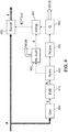
- this figure 7 illustrates an example of a structural embodiment of a codec (coder or decoder) within the meaning of the invention.
- codec coder or decoder
- the coder's strategy is to decorrelate the channels of the ambisonic signal as much as possible and to encode them with a core codec. This strategy makes it possible to limit the artefacts in the decoded ambisonic signal. More particularly, one seeks to apply an optimized decorrelation of the input channels before multi-mono coding here.
- an interpolation of which the computation cost for the encoder and the decoder is limited because it is carried out in a specific domain makes it possible to interpolate the covariance matrices calculated for the PCA / KLT analysis rather than repeating a decomposition into eigenvalues and eigenvectors several times per frame.
- the latter can typically be an extension of the standardized 3GPP EVS (for “Enhanced Voiced Services”) encoder.
- the EVS coding rates can be used without then modifying the structure of the EVS binary train.
- the multi-mono coding (block 340 of the figure 3 described later) operates here with a possible allocation to each transformed channel, restricted to the following bit rates for super-wide audio band coding: 9.6; 13.2; 16.4; 24.4; 32; 48; 64; 96 and 128 kbit / s.
- additional bit rates to have a finer allocation granularity
- the block 300 receives an input signal Y in the current frame of index t.
- the index is not indicated here so as not to weigh down the ratings.
- This is a matrix of size nx L.
- n 4 channels W, Y, Z, X (thus defined according to the order ACN) which can be standardized according to the SN3D convention.
- the order of the channels can be alternately, for example W, X, Y, Z (following the FuMA convention) and the normalization can be different (N3D or FuMa).
- the signal (in each channel) is sampled at 48 kHz, without loss of generality.
- the block 300 of the encoder applies a pre-processing (optional) to obtain the pre-processed input signal denoted Y.
- This may be a high-pass filtering (with a cutoff frequency typically at 20 Hz) of each new one. 20 ms frame of the input signal channels. This operation removes the DC component likely to bias estimating the covariance matrix so that at the output of block 300 the signal can be considered to have zero mean.
- a low pass filter of block 340 can also be implemented to perform multi-mono encoding but when block 300 is implemented the high pass filtering in preprocessing of the mono encoding which can be used in block 340 is preferably disabled to avoid repeating the same preprocessing and thus reduce overall complexity.
- M B ⁇ AT 1 / 2 1 6 0 1 12 1 / 2 - 1 6 0 1 12 1 / 2 0 1 6 - 1 12 1 / 2 0 - 1 6 - 1 12 1 / 2 0 - 1 6 - 1 12
- the following block 310 estimates at each frame t a transformation matrix obtained by determining the eigenvectors by PCA / KLT and checking that the transformation matrix formed by these eigenvectors indeed characterizes a rotation. Details of the block operation 310 are given below with reference to figure 4 .
- This transformation matrix performs a matrixing of the channels to de-correlate them making it possible to apply an independent coding of the multi-mono type by the block 340.
- the block 310 transmits to the multiplexer quantization indices representing the matrix of transformation and optionally information encoding the number of interpolations of the transformation matrix, per sub-frame of the current frame t, as also detailed further below.
- Block 320 determines the optimal rate allocation for each channel (after PCA / KLT transformation) as a function of a given B-bit budget. This block seeks a distribution of the bit rate between channels by calculating a score for each possible combination of bit rates; the optimal allocation is found by looking for the combination maximizing this score. Several criteria can be used to define a score for each combination. For example, the number of possible rates for mono encoding of a channel may be limited to the nine discrete rates of the EVS codec having super-wide audio band: 9.6; 13.2; 16.4; 24.4; 32; 48; 64; 96 and 128 kbit / s.
- the codec according to the invention operates at a given bit rate associated with a budget of B bits in the current frame of index t, in general only a subset of these listed bit rates can be used.
- ⁇ i 1 not b t , i ⁇ B S b t , 1 .. b t , not
- the factor E i can be fixed at the value taken by the eigenvalue associated with the channel i resulting from the decomposition into eigenvalues of the signal at the input of block 310 and after possible signed permutation.
- MOS score values for each of the listed bit rates can be derived from other tests (subjective or objective) predicting the quality of the codec. It is also possible to adapt the MOS notes used in the current frame according to a classification of the type of signal (for example a speech signal without background noise, or speech with ambient noise, or music or mixed content), by reusing classification methods implemented by the EVS codec and by applying them to the W channel of the ambisonic input signal before performing the binary allocation.
- the MOS score can also correspond to an average score resulting from different types of methodologies and rating scales: MOS (absolute) from 1 to 5, DMOS (from 1 to 5), MUSHRA (from 0 to 100).
- the list of bit rates b i and the notes Q ( b i ) can be replaced as a function of this other codec. It is also possible to add additional coding rates to the EVS encoder and therefore complete the list of rates and MOS notes, or even modify the EVS encoder and potentially the associated MOS notes.
- the allocation between the channels is refined by weighting the energy by a power ⁇ where ⁇ takes a value between 0 and 1.
- ⁇ takes a value between 0 and 1.
- a second weighting can be added to the score function to penalize inter-frame rate changes.
- a penalty is added to the score if the rate combination is not the same in frame t as in frame t - 1.
- This additional weighting makes it possible to limit the too frequent fluctuations in flow rate between the channels. With this weighting, only significant changes in energy cause a change in flow. It is also possible to vary the value of the constant to adjust a stability of the allocation.
- this bit rate is coded by block 330, for example exhaustively for all the bit rate combinations.
- the index can then be represented by a coding of the type "permutation code” + “offset of the combination”; for example in the example where we code on a 4-bit index the 16 bit rate combinations comprising 4 permutations of (13.2, 13.2, 13.2, 9.6) and 12 permutations of (16.4, 13.2, 9.6, 9.6), we can use indices 0-3 to code the first 4 possible permutations (with an offset of 0 and a code ranging from 0 to 3) and the indices 4-15 to code the 12 other possible permutations (with an offset of 4 and a code of 0 to 11).
- this matrix can be replaced by the correlation matrix, where the channels are pre-normalized by their respective standard deviation, or generally weights reflecting a relative importance can be applied to each of the channels; moreover, the normalization term 1 / ( L - 1) can be omitted or replaced by another value (for example 1 / L ).
- the values C ij correspond to the variance between x i and x j .
- the encoder then performs in block 410 an eigenvalue decomposition (EVD for “Eigenvalue Decomposition”), by calculating the eigenvalues and the eigenvectors of the matrix C.
- the eigenvectors are noted here V t to indicate the frame index t because the eigenvectors V t -1 obtained in the previous frame of index t - 1 are preferably stored and used subsequently.
- the eigenvalues are denoted ⁇ 1 , ⁇ 2 , ..., ⁇ n .
- a singular value decomposition (SVD) of the X preprocessed channels can be used.
- V singular value decomposition
- the encoder then applies in block 420 a first signed permutation of the columns of the transformation matrix for the frame t (the columns of which are the eigenvectors) in order to avoid too much disparity with the transformation matrix of the previous frame t - 1, which would cause click problems at the border with the previous frame.
- the eigenvectors of frame t are permuted so that the associated basis are as close as possible to the basis of frame t - 1. This has the effect of improving the continuity of the transformed signal frames (once the transformation matrix is applied to the channels).
- transformation matrix must correspond to a rotation. This constraint makes it possible to guarantee that the encoder can convert the transformation matrix into generalized Euler angles (block 430) in order to quantize them (block 440) with a predetermined bit budget as seen previously. For this purpose, the determinant of this matrix must be positive (equal to +1 typically).
- the transformation matrix resulting from blocks 410 and 420 is an orthogonal (unitary) matrix which can have a determinant at -1 or 1, that is to say a reflection or rotation matrix.
- the transformation matrix is a reflection matrix (if its determinant is equal to -1), it can be modified into a rotation matrix by inverting an eigenvector (for example the eigenvector associated with the lowest value) or by inverting two columns (eigenvectors).
- eigenvector for example the eigenvector associated with the lowest value
- eigenvectors two columns
- Certain methods of decomposition into eigenvalues for example by Givens rotation
- transformation matrices which are intrinsically matrices of rotation (with a determinant at +1); in this case, the step of verifying that the determinant is +1 will be optional.
- Block 430 converts the rotation matrix into parameters.
- an angular representation is used for the quantification (6 generalized Euler angles for the 4D case, 3 Euler angles for the 3D case, and one 2D angle).
- For the ambisonic case (four channels) we obtain six Euler angles generalized according to the method described in the article “Generalization of Euler Angles to N-Dimensional Orthogonal Matrices” by David K. Hoffman, Richard C. Raffenetti, and Klaus Ruedenberg , published in Journal of Mathematical Physics 13, 528 (1972); for the case of planar ambisonics (three channels), three Euler angles are obtained and for the stereo case, an angle of rotation is obtained according to the methods well known in the state of the art.
- the values of the angles are quantized in block 440 with a predetermined budget of bits.
- a scalar quantization is used and the quantization step is for example identical for each angle.
- we code 6 Euler angles generalized with 3x (8 + 9) 51 bits (3 angles defined on an interval of [- ⁇ / 2, ⁇ / 2] coded on 8 bits with a step of ⁇ / 256 and the 3 other angles defined on an interval of [- ⁇ , ⁇ ] coded on 9 bits with one with a step of ⁇ / 256).
- the quantization indices of the transformation matrix are sent to the multiplexer (block 350).
- the block 440 will be able to convert the quantized parameters into a quantized rotation matrix V ⁇ t , if the parameters used for the quantization do not correspond to the parameters used for the interpolation.
- the number of interpolations can be fixed (equal to a predetermined value) or adaptive. Each frame is then divided into sub-frames as a function of the number of interpolations determined in the block 450.
- the block 450 can code on a chosen number of bits the number of interpolations to be performed, and therefore the number of sub-frames to be provided, in the case where this number is determined adaptively; in the case of a fixed interpolation, no information is to be coded.
- block 460 converts the rotation matrices to a specific domain representing a rotation matrix.
- the frame is divided into sub-frames, and in the chosen domain the interpolation is performed for each sub-frame.
- the encoder reconstructs from the 6 quantized Euler angles a quantized 4D rotation matrix and that- ci is then converted to two unit quaternions for interpolation purposes.
- the encoder reconstructs from the 3 quantized Euler angles a quantized 3D rotation matrix and the latter is then converted to a unitary quaternion for interpolation purposes.
- the encoder uses in block 460 the representation of the 2D rotation quantized with a rotation angle.
- the rotation matrix calculated for frame t is factored into 2 quaternions (a double quaternion) thanks to the Cayley factorization and we use the double quaternion memorized for the previous frame t -1 and noted ( Q L, t -1 , Q R, t -1 ).
- the quaternions two by two are interpolated in each sub-frame.
- the block determines the shortest path between the two possible ( Q L , t or -Q L , t ). Depending on the case, the sign of the quaternion of the current frame is reversed.
- the matrices V t interp ⁇ (or their transposed) computed by subframe in the interpolation block 460 are then used in the transformation block 470 which produces n channels transformed by applying the rotation matrices thus found, to the ambisonic channels which have been preprocessed by the block 300.
- the final difference between the corrected rotation matrix of the frame t and the rotation matrix of the frame t - 1 gives a measure of the importance of the difference in matrixing of the channels between the two frames.
- the greater this difference the greater the number of subframes for the interpolation made in block 460.
- I n is the identity matrix
- V t the vectors specific to the frame of index t
- ⁇ M ⁇ is a norm of the matrix M which corresponds here to the sum of the absolute values of all the coefficients.
- Other matrix standards can be used (for example the Frobenius standard).
- the realization of the interpolation makes it possible to apply in fine an optimization of the decorrelation of the input channels before multi-mono coding.
- the rotation matrices calculated respectively for a previous frame t -1 and a current frame t can be very different because of this search for decorrelation, but the interpolation nevertheless makes it possible to smooth this difference.
- the interpolation used requires a limited calculation cost for the encoder and the decoder since it is carried out in a specific domain (angle in 2D, quaternion in 3D, double quaternion in 4D). This approach is more advantageous than interpolating covariance matrices calculated for the PCA / KLT analysis and repeating an eigenvalue decomposition type EVD (for “EigenValue Decomposition”) several times per frame.
- Block 470 then performs the matrixing of the ambisonic channels by subframe using the transformation matrices calculated in block 460. This matrixing amounts to calculating by subframe.
- the signal contained in these channels is then sent to block 340 for encoding multi-monos.
- Block 510 After demultiplexing of the binary train for the current frame t by block 500, the allocation information is decoded (block 510) which makes it possible to de-multiplex and decode (block 520) the binary train (s) (s) received for each of the n transformed channels.
- Block 520 calls for multiple instances executed separately from core decoding.
- the core decoding can be of the EVS type optionally modified to improve its performance.
- each channel is decoded separately. If the Previously used encoding is stereo or multi-channel encoding, the multi-mono approach can be replaced by multi-stereo or multi-channel for decoding.
- the channels thus decoded are sent to block 530 which decodes the rotation matrix for the current frame and optionally the number K of subframes to be used for the interpolation (if the interpolation is adaptive).
- the interpolation block 460 splits the frame into sub-frames whose number K can be read in the stream encoded by block 610 ( figure 6 ) and interpolates the rotation matrices, the aim being to find - in the absence of transmission errors - the same matrices as in block 460 of the encoder in order to be able to reverse the transformation which was previously done in block 470.
- Block 530 performs the matrixing inverting that of block 470 to reconstruct a decoded signal, as detailed below with reference to figure 6 .
- Block 530 globally performs the decoding and reverse PCA / KLT synthesis that was performed by block 310 of the figure 3 .
- the quantization indices of the rotation quantization parameters in the current frame are decoded in block 600. Scalar quantization can be used and the quantization step is identical for each angle.
- the number of interpolation sub-frames is decoded (block 610) to find the number K of sub-frames among the set ⁇ 10, 48, 96, 192 ⁇ ; in variants where the length of frames L is different, this set of values may be adapted.
- the interpolation of the decoder is identical to that performed at the encoder (block 460).
- Block 620 performs the reverse matrixing of the ambisonic channels per subframe using the inverses (transposed in practice) of the transformation matrices calculated in block 460.
- the invention uses a completely different approach than the add / overlap MPEG-H codec based on a specific representation of transformation matrices which are restricted to matrices of rotation from one frame to another, in the temporal domain, allowing in particular an interpolation of the transformation matrices, with a mapping which ensures a coherence in direction (including by taking into account the direction by the sign).
- the general approach of the invention is a coding of ambisonic sounds in the time domain by PCA with in particular PCA transformation matrices forced to be rotation matrices and interpolated by sub-frames in an optimized manner (in particular in the field of quaternions / double quaternions) to improve the quality.
- the interpolation step is either fixed or adaptive as a function of a criterion of difference between an inter-correlation matrix and a reference matrix (identity) or between matrices to be interpolated.
- the quantification of the rotation matrices can be implemented in the domain of generalized Euler angles.
Abstract
L'invention concerne le codage en compression de signaux sonores formant une succession dans le temps de trames d'échantillons, dans chacun de N canaux en représentation ambisonique d'ordre supérieur à 0, le procédé comportant :- former, à partir des canaux pour une trame courante, une matrice de covariance entre canaux et rechercher (S3) des vecteurs propres de la matrice de covariance pour obtenir une matrice de vecteurs propres,- tester (S5) la matrice de vecteurs propres pour vérifier qu'elle représente une rotation dans un espace de dimension N et corriger (S6) sinon la matrice de vecteurs propres jusqu'à obtenir une matrice de rotation, pour la trame courante, et- appliquer ladite matrice de rotation (S7) aux signaux des N canaux avant un encodage par canaux séparés desdits signaux.The invention relates to the compression coding of sound signals forming a succession in time of frames of samples, in each of N channels in ambisonic representation of order greater than 0, the method comprising: - forming, from the channels for a current frame, a covariance matrix between channels and find (S3) eigenvectors of the covariance matrix to obtain an eigenvector matrix, - test (S5) the eigenvector matrix to verify that it represents a rotation in a space of dimension N and correct (S6) if not the matrix of eigenvectors until a rotation matrix is obtained, for the current frame, and - apply said rotation matrix (S7) to the signals of the N channels before encoding by channels separated from said signals.
Description
La présente invention concerne le codage/décodage de données sonores spatialisées, notamment en contexte ambiophonique (noté ci-après également « ambisonique »).The present invention relates to the encoding / decoding of spatialized sound data, in particular in a surround sound context (hereinafter also referred to as “ambisonic”).
Les codeurs/décodeurs (ci-après appelés « codecs ») qui sont utilisés actuellement en téléphonie mobile sont mono (un seul canal de signal pour une restitution sur un seul haut-parleur). Le codec 3GPP EVS (pour « Enhanced Voice Services ») permet d'offrir une qualité « Super-HD » (aussi appelée voix « Haute Définition + » ou HD+) avec une bande audio en bande super-élargie (SWB pour « super-wideband » en anglais) pour des signaux échantillonnés à 32 ou 48 kHz ou pleine bande (FB pour « Fullband ») pour des signaux échantillonnés à 48 kHz ; la largeur de bande audio est de 14,4 à 16 kHz en mode SWB (de 9,6 à 128 kbit/s) et de 20 kHz en mode FB (de 16,4 à 128 kbit/s).The coders / decoders (hereinafter called “codecs”) which are currently used in mobile telephony are mono (a single signal channel for reproduction on a single loudspeaker). The 3GPP EVS (for “Enhanced Voice Services”) codec makes it possible to offer “Super-HD” quality (also called “High Definition +” or HD + voice) with an audio band in super-wide band (SWB for “super- wideband "in English) for signals sampled at 32 or 48 kHz or full band (FB for" Fullband ") for signals sampled at 48 kHz; the audio bandwidth is 14.4 to 16 kHz in SWB mode (9.6 to 128 kbit / s) and 20 kHz in FB mode (16.4 to 128 kbit / s).
La prochaine évolution de qualité dans les services conversationnels proposés par les opérateurs devrait être constituée par les services immersifs, en utilisant des terminaux tels que des smartphones par exemple équipés de plusieurs microphones ou des équipements de conférence audio spatialisée ou de visioconférence de type télé-présence, ou encore des outils de partage de contenus « live », avec un rendu sonore spatialisé en 3D, autrement plus immersif qu'une simple restitution stéréo 2D. Avec les usages de plus en plus répandus d'écoute sur téléphone mobile avec un casque audio et l'apparition d'équipements audio avancés (accessoires tels qu'un microphone 3D, assistants vocaux avec antennes acoustiques, casques de réalité virtuelle, etc.) et d'outils spécifiques (par exemple de la production de contenu vidéo 360°) la captation et le rendu de scènes sonores spatialisées sont désormais assez communes pour offrir une expérience de communication immersive.The next quality development in conversational services offered by operators should be immersive services, using terminals such as smartphones, for example, equipped with several microphones or spatialized audio conferencing or tele-presence type videoconferencing equipment. , or even “live” content sharing tools, with spatialized 3D sound rendering, which is far more immersive than a simple 2D stereo rendering. With the more and more widespread use of listening on mobile phones with an audio headset and the appearance of advanced audio equipment (accessories such as a 3D microphone, voice assistants with acoustic antennas, virtual reality headsets, etc.) and specific tools (for example the production of 360 ° video content) the capture and rendering of spatialized sound scenes are now common enough to offer an immersive communication experience.
A ce titre, la future norme 3GPP « IVAS » (pour « Immersive Voice And Audio Services ») propose l'extension du codec EVS à l'immersif en acceptant comme format d'entrée du codec au moins les formats de son spatialisé listés ci-dessous (et leurs combinaisons):
- Format multicanal (channel-based en anglais) de type stéréo, 5.1 où chaque canal vient alimenter un haut-parleur (par exemple L et R en stéréo, ou L, R, Ls, Rs et C en 5.1)
- Format objet (object-based en anglais) où des objets sonores sont décrits comme un signal audio (en général mono) associé à des métadonnées décrivant les attributs de cet objet (position dans l'espace, largeur spatiale de la source, etc.), et
- Format ambisonique (scene-based en anglais) qui décrit le champ sonore en un point donné, en général capté par un microphone sphérique ou synthétisé dans le domaine des harmoniques sphériques.
- Multichannel format (channel-based in English) of stereo type, 5.1 where each channel feeds a speaker (for example L and R in stereo, or L, R, Ls, Rs and C in 5.1)
- Object-based format where sound objects are described as an audio signal (generally mono) associated with metadata describing the attributes of this object (position in space, spatial width of the source, etc.) , and
- Ambisonic format (scene-based in English) which describes the sound field at a given point, generally picked up by a spherical microphone or synthesized in the domain of spherical harmonics.
On s'intéresse ci-après typiquement au codage d'un son au format ambisonique, à titre d'exemple de réalisation (au moins certains aspects présentés en lien avec l'invention ci-après pouvant également s'appliquer à d'autres formats que de l'ambisonique).Hereinafter, we are typically interested in the coding of a sound in ambisonic format, by way of example of an embodiment (at least certain aspects presented in connection with the invention below can also be applied to other formats. than ambisonics).
L'ambisonique est une méthode d'enregistrement (« codage » au sens acoustique) de son spatialisé et un système de reproduction (« décodage » au sens acoustique). Un microphone ambisonique (à l'ordre 1) comprend au moins quatre capsules (typiquement de type cardoïde ou sous-cardoïde) arrangées sur une grille sphérique, par exemple les sommets d'un tétraèdre régulier. Les canaux audio associés à ces capsules s'appellent le « A-format ». Ce format est converti dans un « B-format », dans lequel le champ sonore est décomposé en quatre composantes (harmoniques sphériques) notées W, X, Y, Z, qui correspondent à quatre microphones virtuels coïncidents. La composante W correspond à une captation omnidirectionnelle du champ sonore alors que les composantes X, Y et Z, plus directives, sont assimilables à des gradients de pression orientés suivant les trois dimensions de l'espace. Un système ambisonique est un système flexible dans le sens où l'enregistrement et la restitution sont séparés et découplés. Il permet un décodage (au sens acoustique) sur une configuration quelconque de haut-parleurs (par exemple, binaural, son « surround » de type 5.1 ou périphonie (avec élévation) de type 7.1.4). Bien entendu, l'approche ambisonique peut être généralisée à plus de quatre canaux en B-format et cette représentation généralisée est couramment nommée « HOA » (pour « Higher-Order Ambisonics »). Le fait de décomposer le son sur plus d'harmoniques sphériques améliore la précision spatiale de restitution lors d'un rendu sur hauts-parleurs.Ambisonics is a recording method ("encoding" in the acoustic sense) of spatialized sound and a reproduction system ("decoding" in the acoustic sense). An ambisonic microphone (at order 1) comprises at least four capsules (typically of the cardoid or sub-cardoid type) arranged on a spherical grid, for example the vertices of a regular tetrahedron. The audio channels associated with these capsules are called “A-format”. This format is converted into a “B-format”, in which the sound field is broken down into four components (spherical harmonics) denoted W, X, Y, Z, which correspond to four coincident virtual microphones. The W component corresponds to an omnidirectional capture of the sound field while the X, Y and Z components, which are more directive, are comparable to pressure gradients oriented along the three dimensions of space. An ambisonic system is a flexible system in the sense that recording and playback are separate and decoupled. It allows decoding (in the acoustic sense) on any speaker configuration (for example, binaural, 5.1-type surround sound or 7.1.4-type periphery (with elevation)). Of course, the ambisonic approach can be generalized to more than four channels in B-format and this generalized representation is commonly called “HOA” (for “Higher-Order Ambisonics”). Breaking down the sound into more spherical harmonics improves the spatial accuracy of reproduction when rendering on loudspeakers.
Un signal ambisonique à l'ordre N comprend (N+1)2 composantes et, à l'ordre 1 (si N=1), on retrouve les quatre composantes de l'ambisonique original qui est couramment appelé FOA (pour First-Order Ambisonics). Il existe aussi une variante dite « planaire » de l'ambisonique qui décompose le son défini dans un plan qui est en général le plan horizontal. Dans ce cas, le nombre de composantes est de 2N+1 canaux. L'ambisonique d'ordre 1 (4 canaux : W, X, Y, Z) et l'ambisonique d'ordre 1 planaire (3 canaux : W, X, Y) sont désignés ci-après par « ambisonique » indistinctement pour faciliter la lecture, les traitements présentés étant applicables indépendamment du type planaire ou non. Si toutefois dans certains passages il est besoin de faire une distinction, les termes « ambisonique d'ordre 1 » et « ambisonique d'ordre 1 planaire » sont utilisés. On remarquera que l'on peut dériver du B-format à l'ordre 1 un signal stéréo (2 canaux) correspondant à des captations stéréo coïncidentes de type Blumlein Crossed Pair (X+Y et X-Y) ou Mid-Side (en combinant W et X pour le Mid et en prenant Y comme Side).An ambisonic signal at order N comprises (N + 1) 2 components and, at order 1 (if N = 1), we find the four components of the original ambisonic which is commonly called FOA (for First-Order Ambisonics). There is also a so-called "planar" variant of ambisonics which breaks down the sound defined in a plane which is generally the horizontal plane. In this case, the number of components is 2N + 1 channels. The first order ambisonics (4 channels: W, X, Y, Z) and the first order planar ambisonics (3 channels: W, X, Y) are hereinafter referred to as “ambisonics” indiscriminately to facilitate reading, the treatments presented being applicable regardless of planar type or not. If, however, in some passages it is necessary to make a distinction, the terms "first-order ambisonics" and "first-order planar ambisonics" are used. Note that we can derive from the 1st order B-format a stereo signal (2 channels) corresponding to coincident stereo pickups of the Blumlein Crossed Pair (X + Y and XY) or Mid-Side type (by combining W and X for Mid and taking Y as Side).
Par la suite, on appelle « son ambisonique » un signal en B-format à un ordre prédéterminé. Dans des variantes, le son ambisonique peut être défini dans un autre format tel que le A-format ou des canaux précombinés par matriçage fixe (conservant le nombre de canaux ou le réduisant à un cas à 3 ou 2 canaux), comme on le verra plus loin.In the following, a B-format signal with a predetermined order is called “ambisonic sound”. In variations, the ambisonic sound can be defined in another format such as A-format or pre-combined channels by fixed matrixing (keeping the number of channels or reducing it to a 3 or 2 channel case), as will be seen. further.
Les signaux à traiter par le codeur/décodeur se présentent comme des successions de blocs d'échantillons sonores appelés « trames » ou « sous-trames » ci-après.The signals to be processed by the encoder / decoder are presented as successions of blocks of sound samples called “frames” or “sub-frames” below.
En outre, ci-après, les notations mathématiques suivent la convention suivante :
- Vecteur : u (minuscule, gras)
- Matrice : A (majuscule, gras)
- Vector: u ( lowercase, bold )
- Matrix: A ( uppercase, bold )
L'approche la plus simple pour coder un signal stéréo ou ambisonique consiste à utiliser un codeur mono et de l'appliquer en parallèle à tous les canaux avec éventuellement une allocation des bits différente selon les canaux. Cette approche est appelée ici « multi-mono » (même si en pratique on peut généraliser l'approche à du multi-stéréo ou une utilisation de plusieurs instances parallèles d'un même codec coeur).The simplest approach to encoding a stereo or ambisonic signal is to use a mono encoder and apply it in parallel to all channels with possibly a different bit allocation depending on the channels. This approach is called here “multi-mono” (even if in practice we can generalize the approach to multi-stereo or a use of several parallel instances of the same core codec).
Une telle réalisation est présentée à la
La qualité associée varie selon le codage mono utilisé, et elle n'est en général satisfaisante qu'à très haut débit, par exemple avec un débit d'au moins 48 kbit/s par canal mono pour un codage EVS. Ainsi à l'ordre 1 on obtient un débit minimal de 4x48 = 192 kbit/s.Such an achievement is presented at the
The associated quality varies according to the mono coding used, and it is generally satisfactory only at very high speed, for example with a data rate of at least 48 kbit / s per mono channel for an EVS coding. Thus at
Les solutions proposées actuellement pour des codecs plus sophistiqués, pour de la spatialisation ambisonique notamment, ne sont pas satisfaisantes, notamment en termes de complexité, retard et utilisation efficace du débit, pour assurer une décorrélation efficace entre canaux ambisoniques.The solutions currently proposed for more sophisticated codecs, for ambisonic spatialization in particular, are not satisfactory, in particular in terms of complexity, delay and efficient use of the bit rate, to ensure efficient decorrelation between ambisonic channels.
Par exemple, le codec MPEG-H pour les sons ambisoniques utilise une opération d'addition-recouvrement qui ajoute du retard et de la complexité, ainsi qu'une interpolation linéaire sur des vecteurs de directions qui est sous-optimale et introduit des défauts. Un problème de base de ce codec est qu'il met en oeuvre une décomposition en composantes prédominantes et ambiance car les composantes prédominantes sont censées être perceptuellement distinctes de l'ambiance, mais cette décomposition n'est pas complètement spécifiée. Le codeur MPEG-H souffre de problème de non-correspondance entre les directions des composantes principales d'une trame à l'autre : l'ordre des composantes (signaux) peut être permuté tout comme les directions associées. C'est la raison pour laquelle le codec MPEG- H utilise une technique de « matching » et d'addition-recouvrement (overlap-add en anglais) afin de résoudre ce problème.For example, the MPEG-H codec for ambisonic sounds uses an add-overlap operation which adds delay and complexity, as well as linear interpolation on direction vectors which is suboptimal and introduces defects. A basic problem with this codec is that it implements a decomposition into predominant components and ambience because the predominant components are supposed to be perceptually distinct from ambience, but this decomposition is not completely specified. The MPEG-H encoder suffers from the problem of non-correspondence between the directions of the principal components from one frame to another: the order of the components (signals) can be swapped just like the associated directions. This is the reason why the MPEG-H codec uses a “matching” and overlap-add technique in order to solve this problem.
Par ailleurs, il serait possible d'utiliser des approches de codage fréquentiel (dans le domaine FFT ou MDCT) plutôt qu'un codage temporel comme dans le codec MPEG-H, mais un traitement des signaux dans le domaine fréquentiel (sous-bandes) oblige à transmettre à un décodeur des données par sous-bande, en augmentant ainsi le débit nécessaire à cette transmission.Furthermore, it would be possible to use frequency coding approaches (in the FFT or MDCT domain) rather than a temporal coding as in the MPEG-H codec, but signal processing in the frequency domain (sub-bands) makes it necessary to transmit data by sub-band to a decoder, thus increasing the bit rate necessary for this transmission.
La présente invention vient améliorer cette situation.
Elle propose à cet effet un procédé de codage en compression de signaux sonores formant une succession dans le temps de trames d'échantillons, dans chacun de N canaux en représentation ambisonique d'ordre supérieur à 0, le procédé comportant :
- former, à partir des canaux pour une trame courante, une matrice de covariance entre canaux et rechercher des vecteurs propres de la matrice de covariance pour obtenir une matrice de vecteurs propres,
- tester la matrice de vecteurs propres pour vérifier qu'elle représente une rotation dans un espace de dimension N et corriger sinon la matrice de vecteurs propres jusqu'à obtenir une matrice de rotation, pour la trame courante, et
- appliquer ladite matrice de rotation aux signaux des N canaux avant un encodage par canaux séparés desdits signaux.
To this end, it proposes a method of coding in compression of sound signals forming a succession in time of frames of samples, in each of N channels in ambisonic representation of order greater than 0, the method comprising:
- form, from the channels for a current frame, a covariance matrix between channels and search for eigenvectors of the covariance matrix to obtain a matrix of eigenvectors,
- test the eigenvector matrix to verify that it represents a rotation in a space of dimension N and otherwise correct the eigenvector matrix until obtaining a rotation matrix, for the current frame, and
- applying said rotation matrix to the signals of the N channels before encoding by separate channels of said signals.
Ainsi, la présente invention permet d'améliorer une décorrélation entre les N canaux à encoder séparément par la suite. Cet encodage séparé est désigné aussi ci-après « encodage multi-mono ».Thus, the present invention makes it possible to improve a decorrelation between the N channels to be encoded separately subsequently. This separate encoding is hereinafter also referred to as “multi-mono encoding”.
Dans une forme de réalisation, le procédé peut comporter en outre :
- coder des paramètres tirés de la matrice de rotation en vue d'une transmission via un réseau. Ces paramètres peuvent être typiquement des valeurs de quaternion et/ou d'angle de rotation et/ou d'angle d'Euler comme on le verra plus loin, ou encore simplement des éléments de cette matrice par exemple.
- encoding parameters taken from the rotation matrix for transmission over a network. These parameters can typically be quaternion and / or rotation angle and / or Euler angle values as will be seen below, or even simply elements of this matrix for example.
Dans une forme de réalisation, le procédé peut comporter en outre :
- comparer la matrice de vecteurs propres obtenue pour la trame courante à une matrice de rotation obtenue pour une trame précédant la trame courante, et
- permuter des colonnes de la matrice de vecteurs propres de la trame courante pour assurer une cohérence avec la matrice de rotation de la trame précédente.
- compare the eigenvector matrix obtained for the current frame with a rotation matrix obtained for a frame preceding the current frame, and
- permute columns of the eigenvector matrix of the current frame to ensure consistency with the rotation matrix of the previous frame.
Toutefois, certaines transformations mises en oeuvre pour l'obtention des vecteurs propres à partir de la matrice de covariance (comme la « PCA/KLT » vue plus loin) sont susceptibles d'inverser le sens de certains des vecteurs propres et il convient alors de vérifier à la fois une cohérence d'axe, puis de direction sur cet axe, de chaque vecteur propre de la matrice de la trame courante. A cet effet, dans une forme de réalisation, la permutation précitée des colonnes permettant d'assurer déjà une cohérence d'axes des vecteurs, le procédé comporte en outre :
- vérifier, pour chaque vecteur propre de la trame courante, une cohérence de direction avec un vecteur-colonne de position correspondante de la matrice de rotation de la trame précédente, et
- en cas d'incohérence, inverser le signe des éléments de ce vecteur propre dans la matrice de vecteurs propres de la trame courante.
- check, for each eigenvector of the current frame, a coherence of direction with a column vector of corresponding position of the rotation matrix of the previous frame, and
- in the event of inconsistency, invert the sign of the elements of this eigenvector in the matrix of eigenvectors of the current frame.
Typiquement, une permutation entre colonnes de la matrice de vecteurs propres inversant le signe d'un déterminant de la matrice de vecteurs propres et le déterminant d'une matrice de rotation étant égal à 1,
on peut estimer le déterminant de la matrice de vecteurs propres, et si ce dernier est égal à -1, on peut alors inverser les signes des éléments d'une colonne choisie de la matrice de vecteurs propres, pour que le déterminant soit égal à 1 et former ainsi une matrice de rotation.Typically, a permutation between columns of the eigenvector matrix inverting the sign of a determinant of the eigenvector matrix and the determinant of a rotation matrix being equal to 1,
we can estimate the determinant of the eigenvector matrix, and if the latter is equal to -1, we can then invert the signs of the elements of a chosen column of the eigenvector matrix, so that the determinant is equal to 1 and thereby form a rotation matrix.
Dans une réalisation, le procédé peut comporter en outre :
- une estimation d'écart entre la matrice de rotation obtenue pour la trame courante et une matrice de rotation obtenue pour une trame précédant la trame courante,
- en fonction de l'écart estimé, déterminer si au moins une interpolation est à opérer entre la matrice de rotation de la trame courante et la matrice de rotation de la trame précédente.
- an estimate of the difference between the rotation matrix obtained for the current frame and a rotation matrix obtained for a frame preceding the current frame,
- as a function of the estimated difference, determining whether at least one interpolation is to be made between the rotation matrix of the current frame and the rotation matrix of the previous frame.
Dans une telle réalisation :
- en fonction de l'écart estimé, il est déterminé un nombre d'interpolations à opérer entre la matrice de rotation de la trame courante et la matrice de rotation de la trame précédente,
- la trame courante est découpée en un nombre de sous-trames correspondant au nombre d'interpolations à opérer, et
- on peut coder au moins ce nombre d'interpolations en vue d'une transmission via le réseau précité.
- as a function of the estimated difference, a number of interpolations to be made between the rotation matrix of the current frame and the rotation matrix of the previous frame is determined,
- the current frame is divided into a number of sub-frames corresponding to the number of interpolations to be operated, and
- at least this number of interpolations can be coded with a view to transmission via the aforementioned network.
Dans une forme de réalisation, la représentation ambisonique est d'ordre 1 et le nombre N de canaux est quatre, et la matrice de rotation de la trame courante est représentée par deux quaternions.In one embodiment, the ambisonic representation is of
Dans ce mode de réalisation et dans le cas d'une interpolation, chaque interpolation pour une sous-trame courante est une interpolation sphérique linéaire (ou « SLERP »), menée en fonction de l'interpolation de la sous-trame précédant la sous-trame courante et à partir des quaternions de la sous-trame précédente.In this embodiment and in the case of an interpolation, each interpolation for a current sub-frame is a linear spherical interpolation (or “SLERP”), carried out as a function of the interpolation of the sub-frame preceding the sub-frame. current frame and from the quaternions of the previous subframe.
Par exemple, l'interpolation sphérique linéaire de la sous-trame courante peut être menée pour obtenir les quaternions de la sous-trame courante comme suit : ![]()
![]()
- Q L,t-1 est l'un des quaternions de la sous-trame précédente t-1,
- Q R,t-1 est l'autre des quaternions de la sous-trame précédente t-1,
- Q L,t est l'un des quaternions de la sous-trame courante t,
- QR,t est l'autre des quaternions de la sous-trame courante t,
- Ω L = Arccos (Q L,t-1 · Q L,t ) ; Ω R = Arccos (Q R,t-1 · QR,t )
- et α correspond à un facteur d'interpolation.
- Q L, t -1 is one of the quaternions of the previous subframe t-1,
- Q R , t -1 is the other of the quaternions of the previous subframe t-1,
- Q L , t is one of the quaternions of the current subframe t,
- Q R, t is the other of the quaternions of the current sub-frame t,
- Ω L = Arccos (Q L , t -1 · Q L , t ); Ω R = Arccos ( Q R, t -1Q R, t )
- and α corresponds to an interpolation factor.
Dans une forme de réalisation, la recherche des vecteurs propres est effectuée par analyse en composantes principales (ou « PCA ») ou par transformée de Karhunen Loeve (ou « KLT »), dans le domaine temporel.
Bien entendu, d'autres réalisations peuvent être envisagées (décomposition en valeurs singulières, ou autres).In one embodiment, the search for the eigenvectors is performed by principal component analysis (or "PCA") or by Karhunen Loeve transform (or "KLT"), in the time domain.
Of course, other embodiments can be considered (decomposition into singular values, or others).
Dans une forme de réalisation, le procédé comporte une étape préalable de prévision de budget d'allocation de bits par canal ambisonique, comprenant :
- pour chaque canal ambisonique, une estimation d'énergie acoustique courante dans le canal,
- la sélection dans une mémoire d'un score prédéterminé, de qualité, fonction de ce canal ambisonique et d'un débit courant dans le réseau,
- l'estimation d'une pondération à opérer pour l'allocation de bits à ce canal, par multiplication du score sélectionné à l'énergie estimée.
- for each ambisonic channel, an estimate of current acoustic energy in the channel,
- the selection in a memory of a predetermined score, of quality, function of this ambisonic channel and of a current flow in the network,
- estimating a weighting to be operated for the allocation of bits to this channel, by multiplying the selected score at the estimated energy.
La présente invention vise aussi un procédé de décodage de signaux sonores formant une succession dans le temps de trames d'échantillons, dans chacun de N canaux en représentation ambisonique d'ordre supérieur à 0, le procédé comportant:
- recevoir, pour une trame courante, en plus des signaux des N canaux de cette trame courante, des paramètres d'une matrice de rotation,
- construire une matrice de rotation inverse à partir desdits paramètres,
- appliquer ladite matrice de rotation inverse à des signaux issus des N canaux reçus, avant un décodage par canaux séparés desdits signaux.
- receive, for a current frame, in addition to the signals of the N channels of this current frame, parameters of a rotation matrix,
- construct an inverse rotation matrix from said parameters,
- applying said inverse rotation matrix to signals from the N received channels, before separate channel decoding of said signals.
La présente invention vise aussi un dispositif de codage comportant un circuit de traitement pour la mise en oeuvre du procédé de codage présenté précédemment.The present invention is also aimed at a coding device comprising a processing circuit for implementing the coding method presented above.
Elle vise aussi un dispositif de décodage comportant un circuit de traitement pour la mise en oeuvre du procédé de décodage ci-avant.It also relates to a decoding device comprising a processing circuit for implementing the above decoding method.
Elle vise aussi un programme informatique comportant des instructions pour la mise en oeuvre du procédé ci-avant, lorsque ces instructions sont exécutées par un processeur d'un circuit de traitement.
Elle vise aussi un support mémoire non-transitoire stockant les instructions d'un tel programme informatique.It also relates to a computer program comprising instructions for implementing the above method, when these instructions are executed by a processor of a processing circuit.
It also relates to a non-transient memory medium storing the instructions of such a computer program.
D'autres avantages et caractéristiques et caractéristiques de l'invention apparaitront à la lecture d'exemples de réalisation présentés dans la description détaillée ci-après, et à l'examen des dessins annexés sur lesquels :
- la
figure 1 illustre un codage multi-mono (état de l'art), - la
figure 2 illustre une succession d'étapes principales d'un exemple procédé au sens de l'invention, - la
figure 3 présente la structure générale d'un exemple de codeur selon l'invention, - la
figure 4 présente détaille l'analyse et la transformation PCA/KLT réaliséepar le bloc 310 du codeur de lafigure 3 , - la
figure 5 présente un exemple de décodeur selon l'invention, - la
figure 6 présente le décodage et la synthèse PCA/KLT inverse de lafigure 4 , au décodage, - la
figure 7 illustre des exemples de réalisation structurelle d'un codeur et d'un décodeur au sens de l'invention.
- the
figure 1 illustrates multi-mono coding (state of the art), - the
figure 2 illustrates a succession of main steps of an example process within the meaning of the invention, - the
figure 3 presents the general structure of an example of an encoder according to the invention, - the
figure 4 presents details the analysis and the PCA / KLT transformation carried out by theblock 310 of the encoder of thefigure 3 , - the
figure 5 presents an example of a decoder according to the invention, - the
figure 6 presents the reverse PCA / KLT decoding and synthesis of thefigure 4 , when decoding, - the
figure 7 illustrates structural embodiments of a coder and a decoder within the meaning of the invention.
L'invention vise à permettre un codage optimisé par :
- un matriçage adaptatif en temporel (en particulier avec une transformation adaptative obtenue par PCA/KLT (« PCA » désignant une analyse en composante principale et « KLT » désignant une transformée de Karhunen Loeve),
- suivi préférentiellement par un codage multi-mono.
De plus, l'invention permet d'assurer une adaptation douce des paramètres de matriçage afin d'éviter des artéfacts de type « clics » en bordure de trame ou des fluctuations trop rapides d'image spatiale, ou encore des artéfacts de codage dus à des variations trop fortes (par exemple liées à des permutations intempestives de sources sonores entre canaux) dans les différents canaux individuels issus du matriçage qui sont ensuite codés par des instances différentes d'un codec mono. Il est présenté ci-après un codage multi-mono avec allocation préférentiellement variable des bits entre canaux (après matriçage adaptatif), mais dans des variantes plusieurs instances d'un codec coeur stéréo ou autre peuvent être utilisées.The invention aims to allow an optimized coding by:
- a temporal adaptive matrixing (in particular with an adaptive transformation obtained by PCA / KLT (“PCA” designating a principal component analysis and “KLT” designating a Karhunen Loeve transform),
- preferably followed by multi-mono coding.
In addition, the invention makes it possible to ensure a gentle adaptation of the mastering parameters in order to avoid "click" type artifacts at the edge of the frame or too rapid fluctuations in the spatial image, or even coding artifacts due to too strong variations (for example linked to untimely permutations of sound sources between channels) in the various individual channels resulting from the mastering which are then coded by different instances of a mono codec. Multi-mono coding is presented below with preferentially variable allocation of the bits between channels (after adaptive matrixing), but in variants several instances of a stereo or other core codec can be used.
Afin de faciliter la compréhension de l'invention, il est rappelé ci-après certains concepts explicatifs concernant les rotations en dimension n, les décompositions de type PCA/KLT ou SVD (« SVD » désignant une décomposition en valeurs singulières).In order to facilitate understanding of the invention, certain explanatory concepts relating to rotations in dimension n, decompositions of the PCA / KLT or SVD type (“SVD” denoting a decomposition into singular values) are recalled below.
Les signaux sont représentés par blocs successifs d'échantillons sonores, ces blocs étant appelés « sous-trames » ci-après.
L'invention utilise une représentation des rotations en dimension n avec des paramètres adaptés pour une quantification par trame et surtout une interpolation efficace par sous-trame. On définit ci-dessous les représentations de rotations utilisées en dimension 2, 3 et 4.The signals are represented by successive blocks of sound samples, these blocks being called “sub-frames” below.
The invention uses a representation of the rotations in dimension n with parameters suitable for a quantization per frame and especially an efficient interpolation per sub-frame. The representations of rotations used in
Une rotation (autour de l'origine) est une transformation de l'espace en dimension n qui modifie un vecteur en un autre vecteur, telle que :
- L'amplitude du vecteur est préservée
- Le produit vectoriel de vecteurs définissant un repère orthonormé avant rotation est préservé après rotation (il n'y a pas de réflexion).
- The amplitude of the vector is preserved
- The cross product of vectors defining an orthonormal coordinate system before rotation is preserved after rotation (there is no reflection).
On utilise dans l'invention plusieurs représentations qui sont équivalentes à la représentation par matrice de rotation :
En deux dimensions (dans un plan 2D) (n=2) : On utilise comme représentation l'angle de rotation comme suit.Several representations are used in the invention which are equivalent to the representation by rotation matrix:
In two dimensions (in a 2D plane) (n = 2): We use as representation the angle of rotation as follows.
Etant donné l'angle de rotation θ on en déduit la matrice de rotation : ![]()
![]()
Etant donnée une matrice de rotation, on peut calculer l'angle θ en observant que la trace de la matrice est 2cos θ. On notera qu'il est également possible d'estimer θ directement à partir d'une matrice de covariance avant d'appliquer une décomposition en composantes principles (PCA) et décomposition en valeurs propres (EVD) présentées plus loin.Given a rotation matrix, we can calculate the angle θ by observing that the trace of the matrix is 2cos θ . It will be noted that it is also possible to estimate θ directly from a covariance matrix before applying a decomposition into main components (PCA) and decomposition into eigenvalues (EVD) presented later.
L'interpolation entre deux rotations d'angles respectifs θ 1 et θ 2 peut se faire par interpolation linéaire entre θ 1 et θ 2, en prenant en compte la contrainte de plus court chemin sur le cercle unité entre ces deux angles.The interpolation between two rotations of respective angles θ 1 and θ 2 can be done by linear interpolation between θ 1 and θ 2 , taking into account the constraint of the shortest path on the unit circle between these two angles.
Dans l'espace en trois dimensions (3D) (n=3): On utilise comme représentation les angles d'Euler et les quaternions. Dans des variantes on pourra utiliser également une représentation par axe-angle qui n'est pas rappelée ici.In three-dimensional space (3D) ( n = 3): Euler angles and quaternions are used as representation. In variants, it is also possible to use a representation by axis-angle which is not recalled here.
Une matrice de rotation de taille 3x3 peut être décomposée en un produit de 3 rotations élémentaires d'angle θ selon les axes x, y, ou z. 


Selon les combinaisons d'axes, les angles sont dits d'Euler ou de Cardan.According to the combinations of axes, the angles are said to be Eulerian or Cardanic.
Une autre représentation des rotations 3D toutefois est donnée par les quaternions. Les quaternions sont une généralisation des représentations par nombres complexes avec quatre composantes sous la forme d'un nombre q = a + bi + cj + dk où i 2 = j 2 = k 2 = ijk = -1.Another representation of 3D rotations however is given by quaternions. Quaternions are a generalization of complex number representations with four components in the form of a number q = a + bi + cj + dk where i 2 = j 2 = k 2 = ijk = -1.
La partie réelle a est appelée scalaire et les trois parties imaginaires (b, c, d) forment un vecteur 3D. La norme d'un quaternion est ![]()
![]()
Etant donné un quaternion unitaire q = a + bi + cj + dk (avec a 2 + b 2 + c 2 + d 2 = 1), la matrice de rotation associée est : 
Les angles d'Euler ne permettent pas d'interpoler correctement des rotations 3D ; pour ce faire on utilise plutôt les quaternions ou la représentation axe-angle. La méthode de l'interpolation SLERP (pour « spherical linear interpolation ») consiste à interpoler selon la formule : ![]()
![]()
![]()
![]()
Cela revient à interpoler en suivant un grand cercle sur une sphère 4D avec une vitesse angulaire constante en fonction de α. Il convient de s'assurer que le plus court chemin est utilisé pour l'interpolant en changeant le signe de l'un des quaternions quand q 1· q 2 < 0. On notera que d'autres méthodes d'interpolation de quaternions peuvent être utilisées (normalized linear interpolation ou nlerp, splines, ...).
On remarquera qu'il est également possible d'interpoler des rotations 3D par le biais de la représentation axe-angle ; dans ce cas l'angle est interpolé comme dans le cas 2D et l'axe peut être interpolé par exemple par la méthode SLERP (en 3D) en s'assurant que le plus court chemin est pris sur une sphère unité 3D et en tenant compte du fait que la représentation donnée par l'axe r et l' angle θ est équivalente à celle donnée par l'axe de direction opposée - r et l'angle 2π - θ.This amounts to interpolating by following a large circle on a 4D sphere with a constant angular speed as a function of α . It should be ensured that the shortest path is used for the interpolant by changing the sign of one of the quaternions when q 1 · q 2 <0. Note that other quaternion interpolation methods can be used (normalized linear interpolation or nlerp, splines, ...).
Note that it is also possible to interpolate 3D rotations through the axis-angle representation; in this case the angle is interpolated as in the 2D case and the axis can be interpolated for example by the SLERP method (in 3D) by ensuring that the shortest path is taken on a 3D unit sphere and by taking into account because the representation given by the r axis and the angle θ is equivalent to that given by the opposite direction axis - r and the angle 2π - θ .
En dimension 4 (n=4), une rotation peut être paramétrée par 6 angles (n(n-1)/2) et on montre que la multiplication de deux matrices de taille 4x4 appelées quaternion ( Q 1) et antiquaternion ![]()
Il est possible de retrouver le double quaternion associé (q 1, q 2) et des matrices de quaternion et antiquaternion associées telles que : 

![]()
It is possible to find the associated double quaternion ( q 1 , q 2 ) and associated quaternion and antiquaternion matrices such as:
Leur produit donne une matrice de taille 4x4 : ![]()
![]()
Inversement, étant donné une matrice de rotation 4x4, on peut factoriser cette matrice en un produit de matrices sous la forme ![]()
![]()
La décomposition en valeurs singulières (singular value decomposition ou SVD en anglais) consiste à factoriser une matrice réelle A de taille m x n sous la forme : ![]()
![]()
Le rang r de A est donné par le nombre de coefficients σi non nuls. On peut donc réécrire la décomposition en valeurs singulières comme: 

Si la somme est limitée à un indice i < r on obtient une matrice « filtrée » qui ne représente que l'information « prépondérante ».
On peut aussi écrire : ![]()
We can also write: ![]()
Qui montre que la matrice A transforme v i en σi u i.Which shows that the matrix A transforms v i into σ i u i .
La SVD de A a une relation avec la décomposition en valeurs propres de A T A et A A T car : ![]()
![]()
![]()
![]()
Les valeurs propres de ∑ T ∑ et ∑ ∑ T sont ![]()
![]()
La SVD peut être interprétée de façon géométrique : l'image d'une sphère en dimension n par la matrice A est en dimension m une hyper-ellipse ayant des axes principaux selon les directions u 1, u 2, ..., u m et de longueur σ1, ..., σm.The SVD can be interpreted in a geometric way: the image of a sphere in dimension n by the matrix A is in dimension m a hyper-ellipse having main axes in the directions u 1 , u 2 , ..., u m and of length σ 1 , ..., σ m .
La transformation de Karhunen Loeve (KLT) d'un vecteur aléatoire x centré en 0 et de matrice de covariance R xx = E [x x T] est définie par: ![]()
![]()
![]()
![]()
![]()
![]()
On peut voir la KLT comme un changement de base, car le produit V T x exprime le vecteur x dans la base donnée par les vecteurs propres.
La transformation inverse est donnée par: ![]()
The inverse transformation is given by: ![]()
La KLT permet de décorréler les composantes de x ; les variances du vecteur transformé y sont les valeurs propres de R xx. The KLT makes it possible to decorrelate the components of x ; the variances of the transformed vector y are the eigenvalues of R xx .
L'analyse en composante principale (PCA) est une technique de réduction de dimensionnalité qui produit des variables orthogonales et maximise la variance des variables après projection (ou de façon équivalente minimiser l'erreur de reconstruction).Principal Component Analysis (PCA) is a dimensionality reduction technique that produces orthogonal variables and maximizes the variance of the variables after projection (or equivalently minimizes the reconstruction error).
La PCA présentée ci-après, bien que s'appuyant aussi sur une décomposition en valeurs propres comme la KLT, est telle que la matrice de covariance estimée R̂ xx est calculée à partir de N vecteurs observés x i , i = 1 ... N de dimension n: 

La décomposition en valeurs propres de R̂ xx sous la forme R̂ xx = VΛV T permet de calculer les composantes principales: y n = V T x n .
La PCA est une transformation par la matrice V T qui projette les données dans une nouvelle base pour maximiser la variance des variables après projection.
On notera que la PCA peut également s'obtenir à partir d'une SVD du signal x i mis sous la forme d'une matrice X de taille n x N. Dans ce cas, on peut écrire : ![]()
The PCA is a transformation by the matrix V T which projects the data into a new basis to maximize the variance of the variables after projection.
Note that the PCA can also be obtained from an SVD of the signal x i put in the form of a matrix X of size nx N. In this case, we can write: ![]()
On vérifie que XX T = UDD TUT qui correspond à une diagonalisation de XX T . Ainsi les vecteurs de projection de la PCA correspondent aux vecteurs colonne de U et la projection donne comme résultat U T X = DV T. It is checked that XX DD T = U T U T which corresponds to a diagonalization XX T. Thus the projection vectors of the PCA correspond to the column vectors of U and the projection gives as result U T X = D V T.
On notera également que la PCA est en général vue comme une technique de réduction de dimensionnalité, pour « compresser » un jeu de données en grande dimension vers un jeu comprenant peu de composantes principales. Dans l'invention, la PCA permet avantageusement de décorréler le signal multidimensionnel en entrée mais on évite de supprimer des canaux (donc réduire le nombre de canaux) pour éviter d'introduire des artéfacts. On force ainsi un débit de codage minimal pour éviter de « tronquer » l'image spatiale, sauf dans des variantes spécifiques où des valeurs propres sont tellement faibles qu'un débit nul peut être autorisé (par exemple pour mieux coder des sons ambisoniques créés artificiellement avec une seule source spatialisée de façon synthétique).It will also be noted that PCA is generally seen as a dimensionality reduction technique, to "compress" a large-dimensional dataset into a set. comprising few principal components. In the invention, the PCA advantageously makes it possible to decorrelate the multidimensional input signal but one avoids eliminating channels (therefore reducing the number of channels) in order to avoid introducing artefacts. A minimum encoding rate is thus forced to avoid "truncating" the spatial image, except in specific variants where eigenvalues are so low that a zero rate can be authorized (for example to better encode ambisonic sounds created artificially. with a single synthetically spatialized source).
On se réfère maintenant à la
L'étape S1 consiste à obtenir les signaux respectifs des canaux ambisoniques (ici quatre canaux W, Y, Z, X dans l'exemple décrit utilisant un ordre de canaux selon la convention ACN pour Ambisonics Channel Number), pour chaque trame t. Ces signaux peuvent être mis sous la forme d'une matrice n x L (pour n canaux ambisoniques (ici 4) et L échantillons par trame).
A l'étape suivante S2, on peut optionnellement pré-traiter les signaux de ces canaux par exemple par un filtre passe-haut comme décrit plus loin en référence à la
A l'étape suivante S3, on applique à ces signaux une analyse en composantes principales PCA ou de façon équivalente une transformée de Karhunen Loeve KLT, pour obtenir des valeurs propres et une matrice de vecteurs propres à partir d'une matrice de covariance des n canaux. Dans des variantes de l'invention une SVD pourra être utilisée.
A l'étape S4, cette matrice de vecteurs propres, obtenue pour la trame courante t, subit des permutations signées pour qu'elle soit la plus alignée possible avec la matrice de même nature de la trame précédente t-1. Dans le principe, on s'assure que l'axe des vecteurs colonnes dans la matrice de vecteurs propres correspond le plus possible à l'axe des vecteurs colonnes à la même place dans la matrice de la trame précédente et sinon, on permute les positions des vecteurs propres de la matrice de la trame courante t qui ne correspondent pas. Ensuite, on s'assure en outre que les directions des vecteurs propres d'une matrice à l'autre coïncident également. En d'autres termes, on ne s'intéresse dans un premier temps qu'aux droites qui portent les vecteurs propres (juste la direction, sans le sens) et on cherche pour chaque droite la droite la plus proche dans la matrice de la trame précédente t-1. Pour cela on permute des vecteurs dans la matrice de la trame courante. Puis dans un second temps, on cherche à faire correspondre l'orientation des vecteurs (sens). Pour cela, on inverse le signe des vecteurs propres qui n'auraient pas le bon sens. Une telle réalisation permet d'assurer une cohérence maximale entre les deux matrices et éviter ainsi des clics audibles entre deux trames lors d'une restitution sonore.
A l'étape S5, on s'assure en outre que la matrice de vecteurs propres de la trame courante t, ainsi corrigée par permutations signées, représente bien l'application d'une rotation (d'un angle pour n =2 canaux, de trois angles d'Euler, d'un axe et d'un angle ou d'un quaternion pour n=3 correspondant à la représentation ambisonique d'ordre 1 planaire W, Y, Z, et de deux quaternions pour n=4 en représentation ambisonique d'ordre 1 de type W,Y,Z,X).
Pour s'assurer qu'il s'agit bien d'une rotation, le déterminant de la matrice de vecteurs propres de la trame courante t, corrigée par permutations, doit être positif et égal à (ou, en pratique, voisin de) +1 à l'étape S6. S'il est égal à (ou proche de) -1, alors il convient de :
- permuter à nouveau deux vecteurs propres (par exemple associés à des canaux de faible énergie, donc peu représentatifs), ou
- préférentiellement d'inverser le signe de tous les éléments d'une colonne (par exemple associée à un canal de faible énergie) à l'étape S6.
On peut alors coder sur un nombre de bits alloués à cet effet des paramètres de cette matrice (comme par exemple la valeur d'angle, d'un axe et d'un angle, ou de quaternion(s) de cette matrice) à l'étape S8. Dans une autre réalisation optionnelle mais avantageuse, dans le cas où il est constaté à l'étape S9 un écart significatif (supérieur à un seuil par exemple) entre la matrice de rotation estimée pour la trame courante t et la matrice de rotation de la trame précédente t-1, on peut déterminer un nombre variables de sous-trames d'interpolation : autrement on fixe ce nombre de sous-trames à une valeur pré-déterminée. L'étape S10 consiste à :
- découper la trame courante en sous-trames, et
- interpoler des matrices à appliquer aux sous-trames successives depuis la matrice de la trame précédente t-1 jusqu'à la matrice de la trame courante t, afin de lisser dans le temps la différence entre les deux matrices.
A l'étape S14, avant d'opérer le multiplexage de l'étape S15 et finir ainsi le procédé de codage en compression, on peut décider d'un nombre de bits à allouer par canal en fonction de la représentativité de ce canal et du débit disponible sur le réseau RES (
Step S1 consists in obtaining the respective signals of the ambisonic channels (here four channels W, Y, Z, X in the example described using a channel order according to the ACN convention for Ambisonics Channel Number), for each frame t. These signals can be put in the form of an n x L matrix (for n ambisonic channels (here 4) and L samples per frame).
In the following step S2, the signals of these channels can optionally be pre-processed, for example by a high-pass filter as described below with reference to
In the next step S3, we apply to these signals a PCA principal component analysis or in an equivalent way a Karhunen Loeve KLT transform, to obtain eigenvalues and an eigenvector matrix from a covariance matrix of the n canals. In variants of the invention an SVD could be used.
In step S4, this matrix of eigenvectors, obtained for the current frame t, undergoes signed permutations so that it is as aligned as possible with the matrix of the same nature of the previous frame t -1. In principle, we make sure that the axis of the column vectors in the matrix of eigenvectors corresponds as much as possible to the axis of the column vectors at the same place in the matrix of the previous frame and if not, we swap the positions eigenvectors of the matrix of the current frame t which do not correspond. Then, one also makes sure that the directions of the eigenvectors from one matrix to another also coincide. In other words, one is interested initially only with the lines which carry the eigenvectors (just the direction, without the direction) and one seeks for each line the line closest in the matrix of the frame previous t-1. For this, vectors are permuted in the matrix of the current frame. Then in a second step, we try to do match the orientation of the vectors (direction). For that, one reverses the sign of the eigenvectors which would not have the good sense. Such an embodiment makes it possible to ensure maximum consistency between the two matrices and thus to avoid audible clicks between two frames during sound reproduction.
In step S5, it is also ensured that the matrix of eigenvectors of the current frame t, thus corrected by signed permutations, indeed represents the application of a rotation (of an angle for n = 2 channels, of three Euler angles, of an axis and of an angle or of a quaternion for n = 3 corresponding to the ambisonic representation of
To ensure that it is indeed a rotation, the determinant of the eigenvector matrix of the current frame t, corrected by permutations, must be positive and equal to (or, in practice, close to) + 1 in step S6. If it is equal to (or close to) -1, then it is advisable to:
- permute again two eigenvectors (for example associated with low energy channels, therefore not very representative), or
- preferably to invert the sign of all the elements of a column (for example associated with a low energy channel) in step S6.
Parameters of this matrix (such as for example the angle value, of an axis and of an angle, or of quaternion (s) of this matrix) can then be coded on a number of bits allocated for this purpose) at l 'step S8. In another optional but advantageous embodiment, in the case where a significant difference (greater than a threshold for example) is observed in step S9 between the rotation matrix estimated for the current frame t and the rotation matrix of the frame previous t -1, it is possible to determine a variable number of interpolation sub-frames: otherwise, this number of sub-frames is fixed at a predetermined value. Step S10 consists of:
- split the current frame into sub-frames, and
- interpolate matrices to be applied to successive subframes from the matrix of the preceding frame t -1 to the matrix of the current frame t, in order to smooth the difference between the two matrices over time.
In step S14, before carrying out the multiplexing of step S15 and thus ending the compression coding method, it is possible to decide on a number of bits to be allocated per channel as a function of the representativeness of this channel and of the speed available on the RES network (
On a illustré sur la
Le dispositif de codage DCOD comporte un circuit de traitement incluant typiquement :
- une mémoire MEM1 pour stocker des données d'instructions d'un programme informatique au sens de l'invention (ces instructions pouvant être réparties entre le codeur DCOD et le décodeur DDEC) ;
- une interface INT1 de réception de signaux ambisoniques répartis sur différents canaux (par exemple quatre canaux W, Y, Z, X à l'ordre 1) en vue de leur codage en compression au sens de l'invention ;
- un processeur PROC1 pour recevoir ces signaux et les traiter en exécutant les instructions de programme informatique que stocke la mémoire MEM1, en vue de leur codage ; et
- une interface
de communication COM 1 pour transmettre les signaux codés via le réseau.
- a memory MEM1 for storing instruction data of a computer program within the meaning of the invention (these instructions being able to be distributed between the DCOD encoder and the DDEC decoder);
- an interface INT1 for receiving ambisonic signals distributed over different channels (for example four channels W, Y, Z, X at order 1) with a view to their coding in compression within the meaning of the invention;
- a processor PROC1 for receiving these signals and processing them by executing the computer program instructions stored in the memory MEM1, with a view to their coding; and
- a
COM 1 communication interface for transmitting the coded signals via the network.
Le dispositif de décodage DDEC comporte un circuit de traitement propre, incluant typiquement :
- une mémoire MEM2 pour stocker des données d'instructions d'un programme informatique au sens de l'invention (ces instructions pouvant être réparties entre le codeur DCOD et le décodeur DDEC comme indiqué précédemment) ;
- une interface COM2 pour recevoir du réseau RES les signaux codés en vue de leur décodage en compression au sens de l'invention ;
- un processeur PROC2 pour traiter ces signaux en exécutant les instructions de programme informatique que stocke la mémoire MEM2, en vue de leur décodage ; et
- une interface de sortie INT2 pour délivrer les signaux décodés sous forme de canaux ambisoniques W', Y', Z', X', par exemple en vue de leur restitution.
- a memory MEM2 for storing instruction data of a computer program within the meaning of the invention (these instructions being able to be distributed between the DCOD encoder and the DDEC decoder as indicated above);
- an interface COM2 for receiving from the network RES the encoded signals with a view to their compression decoding within the meaning of the invention;
- a processor PROC2 for processing these signals by executing the computer program instructions stored in the memory MEM2, with a view to their decoding; and
- an output interface INT2 for delivering the decoded signals in the form of ambisonic channels W ', Y', Z ', X', for example with a view to their reproduction.
Bien entendu, cette
On se réfère maintenant à la
La stratégie du codeur est de dé-corréler au maximum les canaux du signal ambisonique et de les coder avec un codec coeur. Cette stratégie permet de limiter les artéfacts dans le signal ambisonique décodé. Plus particulièrement, on cherche à appliquer une décorrélation optimisée des canaux d'entrée avant un codage multi-mono ici. Par ailleurs, une interpolation dont le coût de calcul pour le codeur et le décodeur est limité car celle-ci est réalisée dans un domaine spécifique (angle en 2D, quaternion en 3D, double quaternion en 4D) permet d'interpoler les matrices de covariance calculées pour l'analyse PCA/KLT plutôt que de répéter plusieurs fois par trame une décomposition en valeurs propres et vecteurs propres.The coder's strategy is to decorrelate the channels of the ambisonic signal as much as possible and to encode them with a core codec. This strategy makes it possible to limit the artefacts in the decoded ambisonic signal. More particularly, one seeks to apply an optimized decorrelation of the input channels before multi-mono coding here. In addition, an interpolation of which the computation cost for the encoder and the decoder is limited because it is carried out in a specific domain (angle in 2D, quaternion in 3D, double quaternion in 4D) makes it possible to interpolate the covariance matrices calculated for the PCA / KLT analysis rather than repeating a decomposition into eigenvalues and eigenvectors several times per frame.
Néanmoins, avant d'aborder le codage coeur opéré au sens de l'invention, il est présenté ici quelques fonctionnalités du codeur qui sont avantageuses comme notamment l'optimisation du budget de bits alloués au codage en fonction de critères perceptifs, vue plus loin.Nevertheless, before approaching the core coding carried out within the meaning of the invention, a few functions of the coder which are advantageous, such as in particular the optimization of the budget of bits allocated to coding as a function of perceptual criteria, are presented here below.
Dans le mode de réalisation décrit ici du codeur, ce dernier peut être typiquement une extension du codeur normalisé 3GPP EVS (pour « Enhanced Voiced Services »). Avantageusement, on peut reprendre les débits de codage EVS sans modifier alors la structure du train binaire EVS. Ainsi, le codage multi-mono (bloc 340 de la
Bien entendu, il est possible d'ajouter des débits supplémentaires (pour avoir une granularité d'allocation plus fine) en modifiant le codec EVS. On peut utiliser aussi un autre codec que de type EVS, par exemple le codec OPUS®.In the embodiment described here of the encoder, the latter can typically be an extension of the standardized 3GPP EVS (for “Enhanced Voiced Services”) encoder. Advantageously, the EVS coding rates can be used without then modifying the structure of the EVS binary train. Thus, the multi-mono coding (block 340 of the
Of course, it is possible to add additional bit rates (to have a finer allocation granularity) by modifying the EVS codec. It is also possible to use a codec other than the EVS type, for example the OPUS® codec.
De manière générale, on retient que plus la granularité de codage est fine, et plus il faut réserver de bits pour représenter les combinaisons de débits possibles. Un compromis entre finesse d'allocation et information supplémentaire décrivant l'allocation binaire doit être opéré. Cette allocation est optimisée ici par le bloc 320 de la
En référence à la
On suppose que le signal (dans chaque canal) est échantillonné à 48 kHz, sans perte de généralité. La longueur de trame est fixée à 20 ms, soit L =960 échantillons successifs, sans perte de généralité. Dans des variantes on pourra par exemple utiliser une longueur de trames de L = 640 échantillons pour un échantillonnage à 32 kHz.It is assumed that the signal (in each channel) is sampled at 48 kHz, without loss of generality. The frame length is fixed at 20 ms, ie L = 960 successive samples, without loss of generality. In variants, it is possible for example to use a frame length of L = 640 samples for sampling at 32 kHz.
L'analyse PCA/KLT et la transformation PCA/KLT qui sont décrites plus loin sont effectuées dans le domaine temporel. On comprend ainsi que l'on reste ici dans le domaine temporel sans besoin nécessairement d'opérer une transformée en sous-bandes ou plus généralement fréquentielle.The PCA / KLT analysis and the PCA / KLT transformation which are described later are performed in the time domain. It is thus understood that one remains here in the time domain without necessarily having to operate a sub-band or more generally frequency transform.
A chaque trame, le bloc 300 du codeur applique un prétraitement (optionnel) pour obtenir le signal d'entrée prétraité noté Y. Il peut s'agir d'un filtrage passe-haut (de fréquence de coupure typiquement à 20Hz) de chaque nouvelle trame de 20 ms des canaux du signal d'entrée. Cette opération permet d'enlever la composante continue susceptible de biaiser l'estimation de la matrice de covariance de sorte qu'en sortie du bloc 300 le signal peut être considéré comme étant à moyenne nulle. La fonction de transfert est notée Hpre (z), ainsi on a pour chaque canal : Xi (z) = Hpre (z)Yi (z). Si le bloc 300 n'est pas mis en oeuvre on a X = Y. On peut mettre en oeuvre aussi un filtre passe-bas du bloc 340 pour effectuer le codage multi-mono mais lorsque le bloc 300 est mis en oeuvre, le filtrage passe-haut en prétraitement du codage mono qui peut être utilisé dans le bloc 340 est de façon préférentielle désactivé pour éviter de répéter le même prétraitement et réduire ainsi la complexité globale.At each frame, the
La fonction de transfert notée Hpre (z) ci-dessus peut être du type : 
En variante, on peut utiliser un autre type de filtre, par exemple un filtre de Butterworth d'ordre 6 avec une fréquence à 50 Hz.
Dans des variantes, le pré-traitement pourra inclure une étape de matriçage fixe qui pourra garder le même nombre de canaux ou réduire le nombre de canaux. Un exemple de matriçage appliqué aux quatre canaux d'un signal ambisonique en B-format est donné ci-dessous : 
In variants, the pre-processing could include a fixed die-stamping step which could keep the same number of channels or reduce the number of channels. An example of matrixing applied to the four channels of an ambisonic signal in B-format is given below:
On notera que dans ce cas ce prétraitement devra être inversé au décodage en appliquant un matriçage par M A→B = MB→A -1 du signal décodé pour retrouver les canaux au format d'origine.It will be noted that in this case this preprocessing will have to be reversed on decoding by applying a matrixing by M A → B = M B → A -1 of the decoded signal to find the channels in the original format.
Le bloc suivant 310 estime à chaque trame t une matrice de transformation obtenue par détermination des vecteurs propres par PCA/KLT et vérification que la matrice de transformation que forment ces vecteurs propres caractérise bien une rotation. Des précisions quant à l'opération de bloc 310 sont données plus loin en référence à la
Le bloc 320 détermine l'allocation de débit optimale pour chaque canal (après transformation PCA/KLT) en fonction d'un budget de bits B donné. Ce bloc cherche une répartition du débit entre canaux en calculant un score pour chaque combinaison possible de débits ; l'allocation optimale est trouvée en cherchant la combinaison maximisant ce score.
Plusieurs critères peuvent être utilisés pour définir un score pour chaque combinaison.
Par exemple, le nombre de débits possibles pour le codage mono d'un canal peut être limité aux neuf débits discrets du codec EVS ayant une bande audio super-élargie : 9,6 ; 13,2 ; 16,4 ; 24,4 ; 32 ; 48 ; 64 ; 96 et 128 kbit/s. Cependant si le codec selon l'invention fonctionne à un débit donné associé à un budget de B bits dans la trame courante d'indice t, en général seul un sous-ensemble de ces débits listés est utilisable. Par exemple si le débit du codec est fixé à 4x13,2 = 52,8 kbits/s pour représenter quatre canaux et si chaque canal reçoit un budget minimal de 9,6 kbit/s pour garantir une bande super-élargie pour chacun des canaux, les combinaisons possibles de débits pour le codage de canaux séparés doivent respecter la contrainte que le débit utilisé reste inférieur au débit disponible qui correspond à : ![]()
Several criteria can be used to define a score for each combination.
For example, the number of possible rates for mono encoding of a channel may be limited to the nine discrete rates of the EVS codec having super-wide audio band: 9.6; 13.2; 16.4; 24.4; 32; 48; 64; 96 and 128 kbit / s. However if the codec according to the invention operates at a given bit rate associated with a budget of B bits in the current frame of index t, in general only a subset of these listed bit rates can be used. For example if the codec bit rate is fixed at 4x13.2 = 52.8 kbits / s to represent four channels and if each channel receives a minimum budget of 9.6 kbit / s to guarantee a super-wide band for each of the channels , the possible combinations of bit rates for coding separate channels must respect the constraint that the bit rate used remains lower than the available bit rate which corresponds to: ![]()
Cela donne en termes de débits par canal les permutations de débit par canal suivantes:
- Singleton (9.6, 9.6, 9.6, 9.6) - total = 38.4
- Permutations de (13.2, 9.6, 9.6, 9.6) - total = 42 kbit/s
- Permutations de (13.2, 13.2, 9.6, 9.6) - total = 45.6 kbit/s
- Permutations de (13.2, 13.2, 13.2, 9.6) - total = 49.2 kbit/s
- Permutations de (16.4, 9.6, 9.6, 9.6) - total = 45.2 kbit/s
- Permutations de (16.4, 13.2, 9.6, 9.6) - total = 48.8 kbit/s
- Permutations de (13.2, 13.2, 13.2, 9.6) - 4 cas et débit non utilisé de 50.5 - 49.2 = 1.3 kbit/s
- et Permutations de (16.4, 13.2, 9.6, 9.6) - 12 cas et débit non utilisé de 50.5 - 48.8 = 1.7 kbit/s
- Singleton (9.6, 9.6, 9.6, 9.6) - total = 38.4
- Permutations of (13.2, 9.6, 9.6, 9.6) - total = 42 kbit / s
- Permutations of (13.2, 13.2, 9.6, 9.6) - total = 45.6 kbit / s
- Permutations of (13.2, 13.2, 13.2, 9.6) - total = 49.2 kbit / s
- Permutations of (16.4, 9.6, 9.6, 9.6) - total = 45.2 kbit / s
- Permutations of (16.4, 13.2, 9.6, 9.6) - total = 48.8 kbit / s
- Permutations of (13.2, 13.2, 13.2, 9.6) - 4 cases and unused rate of 50.5 - 49.2 = 1.3 kbit / s
- and Permutations of (16.4, 13.2, 9.6, 9.6) - 12 cases and unused rate of 50.5 - 48.8 = 1.7 kbit / s
On observe que le codage du matriçage adaptatif basé sur un traitement PCA/KLT et en autorisant une allocation binaire flexible peut avoir pour effet des bits non utilisés et, pour certains canaux, un débit inférieur (par exemple 9,6 kbit/s) au débit également réparti entre chacun des canaux (par exemple 13,2 kbit/s par canal).
Pour améliorer cette situation, le bloc 320 peut alors évaluer toutes les combinaisons possibles (pertinentes) de débits pour les 4 canaux issus de la transformation PCA/KLT (en sortie du bloc 310) et leur attribuer un score. Ce score est calculé en se basant sur :
- l'énergie de chaque canal, et
- une note moyenne qui peut être pré-mémorisée et issue de tests subjectifs ou objectifs, laquelle note, notée MOS (pour « Mean Opinion Score », s'agissant d'une note moyenne sur un panel de testeurs), est associée au débit alloué.


To improve this situation, the
- the energy of each channel, and
- an average score which can be pre-memorized and resulting from subjective or objective tests, which score, denoted MOS (for "Mean Opinion Score", being an average score on a panel of testers), is associated with the allocated throughput .
L'allocation optimale peut être telle que : ![]()
![]()
En variante, le facteur Ei peut être fixé à la valeur que prend la valeur propre associée au canal i issue de la décomposition en valeurs propres du signal en entrée du bloc 310 et après permutation signée éventuelle.As a variant, the factor E i can be fixed at the value taken by the eigenvalue associated with the channel i resulting from the decomposition into eigenvalues of the signal at the input of
La note MOS Q(bi ) est de façon préférentielle la note de qualité subjective du codec utilisé pour le codage multi-mono dans le bloc 340 pour un budget bi (en nombres de bits) par trame de 20 ms correspondant à un débit Ri = 50 bi (en bits/sec). On peut utiliser au départ les notes MOS subjectives (moyennes) d'un codeur normalisé EVS données par :
Alternativement, d'autres valeurs de notes MOS pour chacun des débits listés peuvent être issues d'autres tests (subjectifs ou objectifs) prédisant la qualité du codec. Il est aussi possible d'adapter les notes MOS utilisées dans la trame courante en fonction d'une classification du type de signal (par exemple un signal de parole sans bruit de fond, ou parole avec bruit ambiant, ou musique ou contenu mixte), en réutilisant des méthodes de classification que met en oeuvre le codec EVS et en les appliquant au canal W du signal ambisonique en entrée avant d'effectuer l'allocation binaire. La note MOS peut aussi correspondre à une note moyenne issue de différents types de méthodologies et d'échelles de notation : MOS (absolu) de 1 à 5, DMOS (de 1 à 5), MUSHRA (de 0 à 100).Alternatively, other MOS score values for each of the listed bit rates can be derived from other tests (subjective or objective) predicting the quality of the codec. It is also possible to adapt the MOS notes used in the current frame according to a classification of the type of signal (for example a speech signal without background noise, or speech with ambient noise, or music or mixed content), by reusing classification methods implemented by the EVS codec and by applying them to the W channel of the ambisonic input signal before performing the binary allocation. The MOS score can also correspond to an average score resulting from different types of methodologies and rating scales: MOS (absolute) from 1 to 5, DMOS (from 1 to 5), MUSHRA (from 0 to 100).
Dans une variante où le codeur EVS est remplacé par un autre codec, la liste de débits bi et les notes Q(bi ) peuvent être remplacées en fonction de cet autre codec. On peut également ajouter des débits supplémentaires de codage au codeur EVS et donc compléter la liste de débits et de notes MOS, ou encore modifier le codeur EVS et potentiellement les notes MOS associées.In a variant where the EVS coder is replaced by another codec, the list of bit rates b i and the notes Q ( b i ) can be replaced as a function of this other codec. It is also possible to add additional coding rates to the EVS encoder and therefore complete the list of rates and MOS notes, or even modify the EVS encoder and potentially the associated MOS notes.
Alternativement encore, l'allocation entre les canaux est affinée en pondérant l'énergie par une puissance α où α prend une valeur entre 0 et 1. En faisant varier la valeur de α, on peut ainsi contrôler l'influence de l'énergie dans l'allocation : plus α est proche de 1 plus l'énergie a de l'importance dans le score, et donc plus l'allocation est inégale entre les canaux. A l'inverse, plus α est proche de 0 moins l'énergie a de l'importance et plus l'allocation est équi-répartie entre les canaux. Le score est donc exprimé sous la forme : 
Alternativement encore, pour rendre l'allocation plus stable, une seconde pondération peut être ajoutée à la fonction de score pour pénaliser les changements de débits inter-trames. Une pénalité est ajoutée au score si la combinaison de débit n'est pas la même dans la trame t que dans la trame t - 1. Le score s'exprime alors sous la forme : 
Cette pondération supplémentaire permet de limiter les fluctuations trop fréquentes de débit entre les canaux. Avec cette pondération, seuls les changements significatifs d'énergie entrainent un changement de débit. On peut en outre varier la valeur de la constante pour régler une stabilité de l'allocation.Alternatively again, to make the allocation more stable, a second weighting can be added to the score function to penalize inter-frame rate changes. A penalty is added to the score if the rate combination is not the same in frame t as in frame t - 1. The score is then expressed in the form:
This additional weighting makes it possible to limit the too frequent fluctuations in flow rate between the channels. With this weighting, only significant changes in energy cause a change in flow. It is also possible to vary the value of the constant to adjust a stability of the allocation.
En référence à nouveau à la ![]()
![]()
En référence à nouveau à la
Dans les trames où une partie du budget global n'est pas utilisé en totalité, le multiplexeur (bloc 350) peut ajouter des bits de bourrage à zéro pour atteindre le budget de bits alloué à la trame courante, soit ![]()
On peut en outre réserver un bit pour pouvoir commuter entre deux modes de codage :
- Codage selon l'invention avec codage de la matrice de rotation, et
- Codage selon l'invention avec une matrice de rotation restreinte à la matrice identité (donc non transmise) ce qui revient à un codage multi-mono direct si la matrice de rotation de la trame précédente était aussi une matrice identité (par exemple quand le signal ambisonique comprend des sources sonores très diffuses ou de multiples sources étalées spatialement autour de certaines directions privilégiées, auquel cas les canaux ambisoniques sont moins corrélés que pour des sons mélangeant des sources plus ponctuelles et isolées).
In frames where part of the overall budget is not fully utilized, the multiplexer (block 350) can add zero stuffing bits to reach the bit budget allocated to the current frame, i.e.
A bit can also be reserved in order to be able to switch between two coding modes:
- Coding according to the invention with coding of the rotation matrix, and
- Coding according to the invention with a rotation matrix restricted to the identity matrix (therefore not transmitted), which amounts to direct multi-mono coding if the rotation matrix of the previous frame was also an identity matrix (for example when the signal ambisonics includes very diffuse sound sources or multiple sources spatially spread around certain preferred directions, in which case the ambisonic channels are less correlated than for sounds mixing more point and isolated sources).
On se réfère maintenant à la ![]()
![]()
En variante, cette matrice peut être remplacée par la matrice de corrélation, où les canaux sont pré-normalisés par leur écart-type respectif, ou de façon générale des pondérations reflétant une importance relative peuvent être appliquées à chacun des canaux ; de plus le terme de normalisation 1/(L - 1) peut être omis ou remplacé par une autre valeur (par exemple 1/L). Les valeurs C ij correspondent à la variance entre xi et xj. Alternatively, this matrix can be replaced by the correlation matrix, where the channels are pre-normalized by their respective standard deviation, or generally weights reflecting a relative importance can be applied to each of the channels; moreover, the
Le codeur effectue ensuite dans le bloc 410 une décomposition en valeurs propres (EVD pour « Eigenvalue Décomposition » en anglais), en calculant les valeurs propres et les vecteurs propres de la matrice C. Les vecteurs propres sont notés ici Vt pour indiquer l'indice de trame t car les vecteurs propres V t-1 obtenus dans la trame précédente d'indice t - 1 sont préférentiellement mémorisés et utilisés par la suite. Les valeurs propres sont notées λ 1, λ 2, ..., λn .The encoder then performs in
Dans une variante, une décomposition en valeurs singulière (SVD) des canaux prétraités X peut être utilisée. On obtient ainsi les vecteurs singuliers (à gauche U et droite V) et les valeurs singulières σi. Dans ce cas on peut considérer que les valeurs propres λi sont ![]()
![]()
Le codeur applique ensuite dans le bloc 420 une première permutation signée des colonnes de la matrice de transformation pour la trame t (dont les colonnes sont les vecteurs propres) afin d'éviter trop de disparité avec la matrice de transformation de la trame précédente t-1, ce qui engendreraient des problèmes de clics à la frontière avec la trame précédente.
Ainsi, une fois qu'un ébauche de la matrice de transformation est obtenue pour la trame t, le bloc 430 prend n vecteurs propres estimés Vt = v t,0,..., v t,n de la trame courante d'indice t et n vecteurs propres V t-1 mémorisés de la trame précédente d'indice t - 1, et applique une permutation signée sur les vecteurs estimés V t pour qu'ils soient le plus proche possible de V t-1. Ainsi les vecteurs propres de la trame t sont permutés pour que la base associée soient la plus proches possibles de la base de la trame t - 1. Cela a pour effet d'améliorer la continuité des trames de signaux transformés (une fois la matrice de transformation appliquée aux canaux).The encoder then applies in block 420 a first signed permutation of the columns of the transformation matrix for the frame t (the columns of which are the eigenvectors) in order to avoid too much disparity with the transformation matrix of the previous frame t - 1, which would cause click problems at the border with the previous frame.
Thus, once a blank of the transformation matrix is obtained for frame t, block 430 takes n estimated eigenvectors V t = v t , 0 , ..., v t , n of the current frame of index t and n eigenvectors V t -1 stored from the previous frame of index t - 1, and applies a signed permutation to the estimated vectors V t so that they are as close as possible to V t -1 . Thus the eigenvectors of frame t are permuted so that the associated basis are as close as possible to the basis of frame t - 1. This has the effect of improving the continuity of the transformed signal frames (once the transformation matrix is applied to the channels).
Une autre contrainte est que la matrice de transformation doit correspondre à une rotation. Cette contrainte permet de garantir que le codeur puisse convertir la matrice de transformation en des angles d'Euler généralisés (bloc 430) pour les quantifier (bloc 440) avec un budget de bits prédéterminé comme vu précédemment. A cet effet, le déterminant de cette matrice doit être positif (égal à +1 typiquement).Another constraint is that the transformation matrix must correspond to a rotation. This constraint makes it possible to guarantee that the encoder can convert the transformation matrix into generalized Euler angles (block 430) in order to quantize them (block 440) with a predetermined bit budget as seen previously. For this purpose, the determinant of this matrix must be positive (equal to +1 typically).
Préférentiellement, la permutation signée optimale est obtenue en deux étapes :
- La première étape (S4 sur la
figure 2 précédemment présentée) fait correspondre les vecteurs les plus proches entre deux trames en se souciant uniquement de l'axe et non de la direction (du sens) de l'axe. Ce problème peut être formulé comme un problème combinatoire d'affectation de tâches, où l'objectif est de trouver la configuration qui minimise un coût. Le coût peut être défini ici comme la trace de la valeur absolue de l'inter-corrélation entre les matrices de vecteurs propres des trames t et t - 1.
Dans un mode de réalisation la méthode « hongroise » (ou « algorithme hongrois ») sert à déterminer l'assignation optimale qui donne une permutation des vecteurs propres de la trame t; - La seconde étape (S6 sur la
figure 2 ) consiste à déterminer la direction/sens de chaque vecteur propre permuté.Le bloc 420 calcule l'inter-corrélation entre les vecteurs propres permutés Ṽt de la trame t et le vecteur propre de la trame t - 1
- The first step (S4 on the
figure 2 previously presented) matches the closest vectors between two frames, looking only at the axis and not the direction (sense) of the axis. This problem can be formulated as a combinatorial task assignment problem, where the objective is to find the configuration which minimizes a cost. The cost can be defined here as the trace of the absolute value of the inter-correlation between the eigenvector matrices of frames t and t - 1.
In one embodiment, the “Hungarian” method (or “Hungarian algorithm”) is used to determine the optimal assignment which gives a permutation of the eigenvectors of the frame t; - The second step (S6 on the
figure 2 ) consists in determining the direction / sense of each permuted eigenvector. Theblock 420 calculates the inter-correlation between the permuted eigenvectors Ṽ t of the frame t and the eigenvector of the frame t - 1
Si une valeur sur la diagonale de la matrice d'inter-corrélation Γ t est négative, cela dénote un changement de signe entre les directions de vecteurs propres. Une inversion de signe est alors opérée sur le vecteur propre correspondant dans Ṽt.
A l'issue des deux étapes la matrice de transformation à la trame t est désignée par Vt de sorte qu'à la trame suivante la matrice mémorisée devienne V t-1. If a value on the diagonal of the inter-correlation matrix Γ t is negative, that denotes a change of sign between the directions of eigenvectors. A sign inversion is then operated on the eigenvector corresponding to Ṽ t .
At the end of the two steps, the frame transformation matrix t is designated by V t so that at the following frame the stored matrix becomes V t -1 .
Dans une variante, la recherche de la permutation signée optimale peut se faire en calculant la matrice de passage ![]()
![]()
- (1, 0, 0, 0) et (1, 0, 0, 0)
- (0, 0, 0, 1) et (0, 0, -1, 0)
- (0, 1, 0, 0) et (0, 0, 0, -1)
- (0, 0, 1, 0) et (0, -1, 0, 0)]
- (0.5, -0.5, -0.5, -0.5) et (0.5, 0.5, 0.5, 0.5)
- (0.5, 0.5, 0.5, 0.5) et (0.5, -0.5, -0.5, -0.5)
- (0.5, -0.5, 0.5, -0.5) et (0.5, -0.5, 0.5, 0.5)
- (0.5, -0.5, 0.5, 0.5) et (0.5, -0.5, -0.5, 0.5)
- (0.5, 0.5, -0.5, 0.5) et (0.5, 0.5, -0.5, -0.5)
- (0.5, -0.5, -0.5, 0.5) et (0.5, 0.5, -0.5, 0.5)
- (0.5, 0.5, -0.5, -0.5) et (0.5, 0.5, 0.5, -0.5)
- (0.5, 0.5, 0.5, -0.5) et (0.5, -0.5, 0.5, -0.5)
- (1, 0, 0, 0) and (1, 0, 0, 0)
- (0, 0, 0, 1) and (0, 0, -1, 0)
- (0, 1, 0, 0) and (0, 0, 0, -1)
- (0, 0, 1, 0) and (0, -1, 0, 0)]
- (0.5, -0.5, -0.5, -0.5) and (0.5, 0.5, 0.5, 0.5)
- (0.5, 0.5, 0.5, 0.5) and (0.5, -0.5, -0.5, -0.5)
- (0.5, -0.5, 0.5, -0.5) and (0.5, -0.5, 0.5, 0.5)
- (0.5, -0.5, 0.5, 0.5) and (0.5, -0.5, -0.5, 0.5)
- (0.5, 0.5, -0.5, 0.5) and (0.5, 0.5, -0.5, -0.5)
- (0.5, -0.5, -0.5, 0.5) and (0.5, 0.5, -0.5, 0.5)
- (0.5, 0.5, -0.5, -0.5) and (0.5, 0.5, 0.5, -0.5)
- (0.5, 0.5, 0.5, -0.5) and (0.5, -0.5, 0.5, -0.5)
L'opération qui est mise en oeuvre dans le bloc suivant 460 suppose que la matrice de transformation après permutation signée est bien une matrice de rotation ; la matrice de transformation est forcément unitaire, mais il faut également que son déterminant soit égal à 1 ![]()
![]()
Or la matrice de transformation issue des blocs 410 et 420 (après EVD et permutations signées) est une matrice orthogonale (unitaire) pouvant avoir un déterminant à -1 ou 1, c'est-à-dire une matrice de réflexion ou de rotation.Now, the transformation matrix resulting from
Si la matrice de transformation est une matrice de réflexion (si son déterminant est égal à -1), elle peut être modifiée en une matrice de rotation en inversant un vecteur propre (par exemple le vecteur propre associé à la plus faible valeur) ou en intervertissant deux colonnes (vecteurs propres).
Certaines méthodes de décomposition en valeurs propres (par exemple par rotation de Givens) ou de décomposition en valeurs singulières peuvent conduire à des matrices de transformation qui sont intrinsèquement des matrices de rotation (avec un déterminant à +1) ; dans ce cas, l'étape de vérification que le déterminant est +1 sera optionnelle.If the transformation matrix is a reflection matrix (if its determinant is equal to -1), it can be modified into a rotation matrix by inverting an eigenvector (for example the eigenvector associated with the lowest value) or by inverting two columns (eigenvectors).
Certain methods of decomposition into eigenvalues (for example by Givens rotation) or of decomposition into singular values can lead to transformation matrices which are intrinsically matrices of rotation (with a determinant at +1); in this case, the step of verifying that the determinant is +1 will be optional.
Le bloc 430 convertit la matrice de rotation en paramètres. Dans le mode de réalisation privilégié, on utilise une représentation angulaire pour la quantification (6 angles d'Euler généralisés pour le cas 4D, 3 angles d'Euler pour le cas 3D, et un angle en 2D). Pour le cas ambisonique (quatre canaux) on obtient six angles d'Euler généralisés selon la méthode décrite dans l'article « Generalization of Euler Angles to N-Dimensional Orthogonal Matrices » de David K. Hoffman, Richard C. Raffenetti, and Klaus Ruedenberg, paru dans Journal of Mathematical Physics 13, 528 (1972); pour le cas de l'ambisonique planaire (trois canaux) on obtient trois angles d'Euler et pour le cas stéréo on obtient un angle de rotation selon les méthodes bien connues de l'état de l'art. Les valeurs des angles sont quantifiées dans le bloc 440 avec budget prédéterminé de bits. Dans le mode de réalisation privilégié une quantification scalaire est utilisée et le pas de quantification est par exemple identique pour chaque angle. Par exemple dans le cas de 4 canaux, on code 6 angles d'Euler généralisés avec 3x(8+9)=51 bits (3 angles définis sur un intervalle de [-π/2, π/2] codés sur 8 bits avec un pas de π/256 et les 3 autres angles définis sur un intervalle de [-π, π] codés sur 9 bits avec un avec un pas de π/256). Les indices de quantification de la matrice de transformation sont envoyés au multiplexeur (bloc 350). De plus, le bloc 440 pourra convertir les paramètres quantifiés en une matrice de rotation quantifiée V̂t , si les paramètres utilisés pour la quantification ne correspondent pas aux paramètres utilisés pour l'interpolation.
En variante, les blocs 430 et 440 peuvent être remplacés comme suit :
Le bloc 430 peut effectuer une conversion des matrices de rotations en un double quaternion unitaire (cas de 4 canaux), en quaternion unitaire (cas de 3 canaux) et en un angle (cas de 2 canaux).
- Block 430 can convert the rotation matrices into a unitary double quaternion (case of 4 channels), unitary quaternion (case of 3 channels) and into an angle (case of 2 channels).
Cette conversion en double quaternion pour le cas 4D pourra être réalisée pour une matrice de rotation dont les coefficients sont notés R[i,j], i,j=0...3, par le pseudo-code suivante :
- Calcul de la matrice associée A[i,j] avec :


- Calcul des 2 quaternions à partir de la matrice associée
- A2 = square(A) # carré de coefficients
- q1 = sqrt(A2.sum(axis=1)) # somme sur le lignes
- q2= sqrt(A2.sum(axis=0)) # somme sur les colonnes
- Pour k=0..3 : Si sign(A[i,k])<0, Alors q2[k] = -q2[k]
- Pour k=0..3 : Si sign(A[k,j])!=sign(q1[k]*q2[j]), Alors q1[k] = -q1[k]
Calcul de la matrice associée simplifiée :


- Calculation of the associated matrix A [i, j] with:
- Calculation of the 2 quaternions from the associated matrix
- A2 = square (A) # square of coefficients
- q1 = sqrt (A2.sum (axis = 1)) # sum on the lines
- q2 = sqrt (A2.sum (axis = 0)) # sum over columns
- For k = 0..3: If sign (A [i, k]) <0, then q2 [k] = -q2 [k]
- For k = 0..3: If sign (A [k, j])! = Sign (q1 [k] * q2 [j]), then q1 [k] = -q1 [k]
Calculation of the simplified associated matrix:
Calcul du quaternion q
Si 
- Si

Si 
- Yes
- Yes
- Yes
Le calcul de l'angle pour le cas d'une matrice 2x2 se fait selon les méthodes de l'état de l'art déjà connue.
Dans des variantes on pourra convertir les quaternions unitaires q1, q2 (cas 4D) et q (cas 3D) en des représentations axe-angle connues de l'état de l'art.
Le bloc 440 peut réaliser une quantification dans le domaine indiqué :- * Cas de 4 canaux : la paire de quaternions unitaires q 1 et q 2 est quantifiée par un dictionnaire de quantification sphérique en dimension 4 ; par convention on quantifie q 1 avec un dictionnaire hémisphérique (car q 1 et -q 1 correspondent à une même rotation 3D) et q 2 est quantifié avec un dictionnaire sphérique. Des exemples de dictionnaires peuvent être donnés par des points prédéfinis à partir de polyèdres de dimension 4 ; dans des variantes on pourra quantifier une double représentation axe-angle associés qui serait équivalente au double quaternion ;
- * Cas de 3 canaux : le quaternion unitaire est quantifié par un dictionnaire de quantification sphérique en dimension 4 - des exemples de dictionnaires peuvent être donnés par des points prédéfinis à partir de polyèdres de dimension 4 ;
- * Cas de 2 canaux : l'angle est quantifié par quantification scalaire uniforme.
In variants, the unit quaternions q1, q2 (4D case) and q (3D case) could be converted into axis-angle representations known from the state of the art.
- Block 440 can perform quantization in the indicated domain:
- * Case of 4 channels: the pair of unitary quaternions q 1 and q 2 is quantized by a spherical quantization dictionary in dimension 4; by convention, q 1 is quantified with a hemispherical dictionary (because q 1 and - q 1 correspond to the same 3D rotation) and q 2 is quantized with a spherical dictionary. Examples of dictionaries can be given by points predefined from polyhedra of dimension 4; in variants, it is possible to quantify a double associated axis-angle representation which would be equivalent to the double quaternion;
- * Case of 3 channels: the unitary quaternion is quantified by a spherical quantization dictionary in dimension 4 - examples of dictionaries can be given by predefined points from polyhedra of dimension 4;
- * Case of 2 channels: the angle is quantized by uniform scalar quantization.
On décrit maintenant le bloc 460 d'interpolation des matrices de rotation entre deux trames successives. Il permet de lisser les discontinuités des canaux après l'application de ces matrices. Typiquement, si deux jeux d'angles ou de quaternions sont trop différents d'une trame précédente t-1 à la suivante t, des clics audibles sont à craindre s'il n'a pas été pratiqué entre ces deux trames une transition lissée dans des sous-trames entre ces deux trames. On réalise alors une interpolation de passage entre la matrice de rotation calculée pour la trame t-1 et la matrice de rotation calculée pour la trame t. Le codeur interpole dans le bloc 460 la représentation (quantifiée) de la rotation entre la trame courante et de la trame précédente pour éviter des fluctuations trop rapides des différents canaux après transformation. Le nombre d'interpolations peut être fixe (égal à une valeur prédéterminée) ou adaptatif. Chaque trame est alors divisée en sous-trames en fonction du nombre d'interpolations déterminé dans le bloc 450. Ainsi, si une interpolation adaptative est utilisée, le bloc 450 peut coder sur un nombre de bits choisi le nombre d'interpolations à effectuer, et donc le nombre de sous-trames à prévoir, dans le cas où ce nombre est déterminé de façon adaptative ; dans le cas d'une interpolation fixe, aucune information n'est à coder.We now describe the
Ensuite, le bloc 460 convertit les matrices de rotation dans un domaine spécifique représentant une matrice de rotations. La trame est découpée en sous-trames, et dans le domaine choisi l'interpolation est effectuée pour chaque sous-trame.
Pour un signal d'entrée ambisonique d'ordre 1 (à 4 canaux W, X, Y, Z), dans le bloc 460, le codeur reconstruit à partir des 6 angles d'Euler quantifiés une matrice de rotation 4D quantifiée et celle-ci est ensuite convertie en deux quaternions unitaires à des fins d'interpolation. Dans une variante où l'entrée du codeur est un signal ambisonique planaire (3 canaux W, X, Y), dans le bloc 460 le codeur reconstruit à partir des 3 angles d'Euler quantifiés une matrice de rotation 3D quantifiée et celle-ci est ensuite convertie en un quaternion unitaire à des fins d'interpolation. Dans une variante où l'entrée du codeur est un signal stéréo, le codeur utilise dans le bloc 460 la représentation de la rotation 2D quantifiée avec un angle de rotation.
Dans le mode de réalisation avec 4 canaux, pour l'interpolation de la matrice de rotation entre la trame t et la trame t - 1, la matrice de rotation calculée pour la trame t est factorisée en 2 quaternions (un double quaternion) grâce a la factorisation de Cayley et on utilise le double quaternion mémorisé pour la trame précédente t-1 et noté (Q L,t-1, Q R,t-1).Next, block 460 converts the rotation matrices to a specific domain representing a rotation matrix. The frame is divided into sub-frames, and in the chosen domain the interpolation is performed for each sub-frame.
For an ambisonic input signal of order 1 (with 4 channels W, X, Y, Z), in
In the embodiment with 4 channels, for the interpolation of the rotation matrix between frame t and frame t - 1, the rotation matrix calculated for frame t is factored into 2 quaternions (a double quaternion) thanks to the Cayley factorization and we use the double quaternion memorized for the previous frame t -1 and noted ( Q L, t -1 , Q R, t -1 ).
Pour chaque sous-trame, on interpole dans chaque sous-trame les quaternions deux à deux.
Pour le quaternion gauche (Q L,t ), le bloc détermine le plus court chemin entre les deux possible (Q L,t ou -Q L,t ). Selon les cas, on inverse le signe du quaternion de la trame courante. Puis l'interpolation est calculée pour le quaternion gauche avec l'interpolation sphérique linéaire (SLERP) : ![]()
For the left quaternion ( Q L , t ), the block determines the shortest path between the two possible ( Q L , t or -Q L , t ). Depending on the case, the sign of the quaternion of the current frame is reversed. Then the interpolation is calculated for the left quaternion with linear spherical interpolation (SLERP): ![]()
Pour le quaternion droit (Q R,t ), s'il y a eu une inversion pour le quaternion gauche alors il faut respecter la parité et forcer le signe du quaternion droit. Cette contrainte de signe est appelée ci-après « contrainte de plus court chemin conjoint ». Puis l'interpolation est calculée de manière similaire au quaternion gauche : ![]()
![]()
Une fois l'interpolation calculée pour les deux quaternions, on calcule la matrice de rotation de dimension 4x4 (respectivement 3x3 pour l'ambisonique planaire ou 2x2 pour le cas stéréo).
Cette conversion en matrice de rotation peut être effectuée selon les pseudo-codes suivants :
- Cas 4D : pour un double quaternion
- Comme décrit précédemment on calcule les matrices de quaternion et antiquaternion et on calcule le produit matriciel.
- Cas 3D : pour quaternion q=(w,x,y,z) on obtient la matrice M[i,j], i,j=0...2, de taille 3x3


This conversion into a rotation matrix can be carried out according to the following pseudo-codes:
- 4D case: for a double quaternion
- As previously described, the quaternion and antiquaternion matrices are calculated and the matrix product is calculated.
- 3D case: for quaternion q = (w, x, y, z) we obtain the matrix M [i, j], i, j = 0 ... 2, of size 3x3
Enfin, les matrices ![]()
![]()
On revient ci-après sur le nombre K de sous-trames à déterminer dans le bloc 450 pour le cas où ce nombre est adaptatif. Il est mesuré l'écart final entre la trame courante et la trame précédente ou directement à partir de la différence angulaire des paramètres décrivant la matrice de rotation. On cherche dans ce dernier cas à faire en sorte que la variation angulaire entre sous-trames successives ne soit pas perceptible. La réalisation d'un nombre de sous-trames adaptatif est surtout avantageuse pour réduire la complexité moyenne du codec mais s'il est choisi de réduire la complexité on peut préférer utiliser une interpolation avec un nombre fixe de sous-trames.We return below to the number K of subframes to be determined in
L'écart final entre la matrice de rotation corrigée de la trame t et la matrice de rotation de la trame t - 1 donne une mesure de l'importance de la différence de matriçage des canaux entre les deux trames. Plus cet écart est important et plus le nombre de sous-trames pour l'interpolation faite dans le bloc 460 est élevé. On utilise la somme de la valeur absolue de la matrice d'inter-corrélation entre la matrice de transformation de la trame courante et la trame précédente, comme suit, pour mesurer cet écart : ![]()
![]()
Dans le cas où les deux matrices sont identiques alors cet écart est égal à 0. Plus les matrices sont dissimilaires, plus la valeur de l'écart δt est élevée. Des seuils prédéterminés peuvent être appliqués à δt , à chaque seuil est associé un nombre prédéfini d'interpolations par exemple selon la logique de décision suivante :
- Seuils : {4.0, 5.0, 6.0, 7.0}
- Nombre K des sous-trames pour interpolation : {10, 48, 96, 192}
Ainsi seuls deux bits peuvent suffire à coder les quatre valeurs possibles donnant le nombre de subdivisions (sous-trames).
Le nombre K d'interpolations déterminépar le bloc 450 est ensuite envoyé aumodule d'interpolation 460 et dans le cas adaptatif le nombre de sous-trames est codé sous la forme d'un indice binaire qui est envoyé au multiplexeur (bloc 350).
- Thresholds: {4.0, 5.0, 6.0, 7.0}
- Number K of subframes for interpolation: {10, 48, 96, 192}
Thus only two bits can suffice to encode the four possible values giving the number of subdivisions (sub-frames).
The number K of interpolations determined by theblock 450 is then sent to theinterpolation module 460 and in the adaptive case the number of subframes is encoded in the form of a binary index which is sent to the multiplexer (block 350) .
La réalisation de l'interpolation permet d'appliquer in fine une optimisation de la décorrélation des canaux d'entrée avant codage multi-mono. En effet, les matrices de rotation calculées respectivement pour une trame précédente t-1 et une trame courante t peuvent être très différentes du fait de cette recherche de décorrélation, mais l'interpolation permet néanmoins de lisser cette différence.
L'interpolation utilisée nécessite un coût de calcul limité pour le codeur et le décodeur puisqu'elle est réalisée dans un domaine spécifique (angle en 2D, quaternion en 3D, double quaternion en 4D). Cette approche est plus avantageuse que d'interpoler des matrices de covariance calculées pour l'analyse PCA/KLT et de répéter plusieurs fois par trame une décomposition en valeurs propres type EVD (pour « EigenValue Décomposition »).The realization of the interpolation makes it possible to apply in fine an optimization of the decorrelation of the input channels before multi-mono coding. In fact, the rotation matrices calculated respectively for a previous frame t -1 and a current frame t can be very different because of this search for decorrelation, but the interpolation nevertheless makes it possible to smooth this difference.
The interpolation used requires a limited calculation cost for the encoder and the decoder since it is carried out in a specific domain (angle in 2D, quaternion in 3D, double quaternion in 4D). This approach is more advantageous than interpolating covariance matrices calculated for the PCA / KLT analysis and repeating an eigenvalue decomposition type EVD (for “EigenValue Decomposition”) several times per frame.
Le bloc 470 effectue ensuite le matriçage des canaux ambisoniques par sous-trame à l'aide des matrices de transformation calculées dans le bloc 460. Ce matriçage revient à calculer par sous-trame ![]()
![]()
On se réfère maintenant à la
Après démultiplexage du train binaire pour la trame courante t par le bloc 500, l'information d'allocation est décodée (bloc 510) ce qui permet de dé-multiplexer et de décoder (bloc 520) le(s) train(s) binaire(s) reçu(s) pour chacun des n canaux transformés.
Le bloc 520 fait appel à plusieurs instances exécutées séparément du décodage coeur. Le décodage coeur peut être de type EVS éventuellement modifié pour améliorer ses performances. Selon une approche multi-mono, chaque canal est décodé séparément. Si le codage précédemment utilisé est un codage stéréo ou multicanal, l'approche multi-mono peut être remplacée par un multi-stéréo ou multicanal pour le décodage. Les canaux ainsi décodés sont envoyés au bloc 530 qui décode la matrice de rotation pour la trame courante et de façon optionnelle le nombre K de sous-trames à utiliser pour l'interpolation (si l'interpolation est adaptative). Pour chaque matrice, le bloc d'interpolation 460 découpe la trame en sous-trames dont le nombre K peut être lu dans le flux codé par le bloc 610 (
After demultiplexing of the binary train for the current frame t by
Le bloc 530 effectue le matriçage inversant celui du bloc 470 pour reconstruire un signal décodé, comme détaillé ci-après en référence à la ![]()
Le bloc 530 effectue globalement le décodage et de la synthèse PCA/KLT inverse qui a été effectué par le bloc 310 de la ![]()
Le bloc 620 effectue le matriçage inverse des canaux ambisoniques par sous-trame à l'aide des inverses (les transposées en pratique) des matrices de transformation calculées dans le bloc 460.
Ainsi, l'invention utilise une toute autre approche que le codec MPEG-H à addition/recouvrement en se basant sur une représentation spécifique des matrices de transformation qui sont restreintes à des matrices de rotation d'une trame à l'autre, dans le domaine temporel, permettant notamment une interpolation des matrices de transformation, avec une mise en correspondance qui assure une cohérence en direction (y compris en prenant en compte le sens par le signe).Thus, the invention uses a completely different approach than the add / overlap MPEG-H codec based on a specific representation of transformation matrices which are restricted to matrices of rotation from one frame to another, in the temporal domain, allowing in particular an interpolation of the transformation matrices, with a mapping which ensures a coherence in direction (including by taking into account the direction by the sign).
L'approche générale de l'invention est un codage de sons ambisoniques dans le domaine temporel par PCA avec notamment des matrices de transformation PCA forcées à être des matrices de rotations et interpolées par sous-trames de façon optimisée (en particulier dans le domaine des quaternions/doubles quaternions) pour améliorer la qualité. Le pas d'interpolation est soit fixe, soit adaptatif en fonction d'un critère d'écart entre une matrice d'inter-corrélation et une matrice de référence (identité) ou entre matrices à interpoler. La quantification des matrices de rotation peut être mise en oeuvre dans le domaine des angles d'Euler généralisés. Cependant il peut être choisi préférentiellement de quantifier les matrices de dimension 3 et 4 dans le domaine des quaternions et doubles quaternions (respectivement), ce qui permet de rester dans le même domaine pour la quantification et l'interpolation.
En outre, un alignement des vecteurs propres est utilisé pour éviter les problèmes de clics et d'inversion de canaux, d'une trame à l'autre.The general approach of the invention is a coding of ambisonic sounds in the time domain by PCA with in particular PCA transformation matrices forced to be rotation matrices and interpolated by sub-frames in an optimized manner (in particular in the field of quaternions / double quaternions) to improve the quality. The interpolation step is either fixed or adaptive as a function of a criterion of difference between an inter-correlation matrix and a reference matrix (identity) or between matrices to be interpolated. The quantification of the rotation matrices can be implemented in the domain of generalized Euler angles. However, it may be preferentially chosen to quantify the matrices of
In addition, eigenvector alignment is used to avoid the problems of clicks and channel inversion from frame to frame.
Bien entendu, la présente invention ne se limite pas aux formes de réalisation décrites ci-avant à titre d'exemple et s'étend à d'autres variantes.Of course, the present invention is not limited to the embodiments described above by way of example and extends to other variants.
Ainsi, la description précédente a traité les cas de quatre canaux.
Néanmoins, dans des variantes, on peut également coder un nombre de canaux supérieur à quatre. La mise en oeuvre reste identique (en termes de blocs fonctionnels) au cas n=4, mais l'interpolation par double quaternion est remplacée par la méthode générale ci-après.
Les matrices de transformation aux trames t - 1 et t sont notées V t-1 et Vt. L'interpolation peut être effectuée avec un facteur α entre V t-1 et Vt tel que : ![]()
However, in variants, it is also possible to encode a number of channels greater than four. The implementation remains identical (in terms of functional blocks) to the case n = 4, but the interpolation by double quaternion is replaced by the general method below.
The transformation matrices at frames t - 1 and t are denoted V t -1 and V t . The interpolation can be performed with a factor α between V t -1 and V t such that: ![]()
Le terme ![]()
![]()
![]()
![]()
On notera également que cette variante pourrait aussi remplacer l'interpolation par double quaternion unitaire (cas 4D), quaternion unitaire (cas 3D) ou angle, cependant elle serait moins avantageuse car elle nécessiterait une étape de diagonalisation supplémentaire et des calculs de puissance, alors que le mode de réalisation décrit précédemment est plus efficace pour ces cas de 2, 3 ou 4 canaux.The term ![]()
![]()
![]()
![]()
Note also that this variant could also replace the interpolation by double unitary quaternion (4D case), unitary quaternion (3D case) or angle, however it would be less advantageous because it would require an additional diagonalization step and power calculations, then that the embodiment described above is more effective for these cases of 2, 3 or 4 channels.
Claims (15)
si le déterminant de la matrice de vecteurs propres est égal à -1, on inverse les signes des éléments d'une colonne choisie de la matrice de vecteurs propres, pour que le déterminant soit égal à 1 et former ainsi une matrice de rotation.Method according to one of the preceding claims, in which a permutation between columns of the eigenvector matrix inverting the sign of a determinant of the eigenvector matrix and the determinant of a rotation matrix being equal to 1,
if the determinant of the eigenvector matrix is equal to -1, the signs of the elements of a chosen column of the eigenvector matrix are reversed, so that the determinant is equal to 1 and thus form a rotation matrix.
Priority Applications (9)
| Application Number | Priority Date | Filing Date | Title |
|---|---|---|---|
| EP19305254.5A EP3706119A1 (en) | 2019-03-05 | 2019-03-05 | Spatialised audio encoding with interpolation and quantifying of rotations |
| JP2021552656A JP7419388B2 (en) | 2019-03-05 | 2020-02-10 | Spatialized audio coding with rotation interpolation and quantization |
| EP20703048.7A EP3935629A1 (en) | 2019-03-05 | 2020-02-10 | Spatialized audio coding with interpolation and quantification of rotations |
| CN202080031569.8A CN113728382A (en) | 2019-03-05 | 2020-02-10 | Spatialized audio codec with rotated interpolation and quantization |
| PCT/EP2020/053264 WO2020177981A1 (en) | 2019-03-05 | 2020-02-10 | Spatialized audio coding with interpolation and quantification of rotations |
| US17/436,390 US11922959B2 (en) | 2019-03-05 | 2020-02-10 | Spatialized audio coding with interpolation and quantization of rotations |
| KR1020217031995A KR20210137114A (en) | 2019-03-05 | 2020-02-10 | Spatialized audio coding via interpolation and quantization of rotations |
| ZA2021/06465A ZA202106465B (en) | 2019-03-05 | 2021-09-03 | Spatialized audio coding with interpolation and quantification of rotations |
| JP2024001364A JP2024024095A (en) | 2019-03-05 | 2024-01-09 | Spatialized audio coding with rotation interpolation and quantization |
Applications Claiming Priority (1)
| Application Number | Priority Date | Filing Date | Title |
|---|---|---|---|
| EP19305254.5A EP3706119A1 (en) | 2019-03-05 | 2019-03-05 | Spatialised audio encoding with interpolation and quantifying of rotations |
Publications (1)
| Publication Number | Publication Date |
|---|---|
| EP3706119A1 true EP3706119A1 (en) | 2020-09-09 |
Family
ID=65991736
Family Applications (2)
| Application Number | Title | Priority Date | Filing Date |
|---|---|---|---|
| EP19305254.5A Withdrawn EP3706119A1 (en) | 2019-03-05 | 2019-03-05 | Spatialised audio encoding with interpolation and quantifying of rotations |
| EP20703048.7A Pending EP3935629A1 (en) | 2019-03-05 | 2020-02-10 | Spatialized audio coding with interpolation and quantification of rotations |
Family Applications After (1)
| Application Number | Title | Priority Date | Filing Date |
|---|---|---|---|
| EP20703048.7A Pending EP3935629A1 (en) | 2019-03-05 | 2020-02-10 | Spatialized audio coding with interpolation and quantification of rotations |
Country Status (7)
| Country | Link |
|---|---|
| US (1) | US11922959B2 (en) |
| EP (2) | EP3706119A1 (en) |
| JP (2) | JP7419388B2 (en) |
| KR (1) | KR20210137114A (en) |
| CN (1) | CN113728382A (en) |
| WO (1) | WO2020177981A1 (en) |
| ZA (1) | ZA202106465B (en) |
Cited By (1)
| Publication number | Priority date | Publication date | Assignee | Title |
|---|---|---|---|---|
| FR3118266A1 (en) * | 2020-12-22 | 2022-06-24 | Orange | Optimized coding of rotation matrices for the coding of a multichannel audio signal |
Families Citing this family (4)
| Publication number | Priority date | Publication date | Assignee | Title |
|---|---|---|---|---|
| EP4256554A1 (en) * | 2020-12-02 | 2023-10-11 | Dolby Laboratories Licensing Corporation | Rotation of sound components for orientation-dependent coding schemes |
| CN115497485A (en) * | 2021-06-18 | 2022-12-20 | 华为技术有限公司 | Three-dimensional audio signal coding method, device, coder and system |
| EP4120255A1 (en) | 2021-07-15 | 2023-01-18 | Orange | Optimised spherical vector quantification |
| FR3136099A1 (en) | 2022-05-30 | 2023-12-01 | Orange | Spatialized audio coding with adaptation of decorrelation processing |
Citations (1)
| Publication number | Priority date | Publication date | Assignee | Title |
|---|---|---|---|---|
| US20160155448A1 (en) * | 2013-07-05 | 2016-06-02 | Dolby International Ab | Enhanced sound field coding using parametric component generation |
Family Cites Families (4)
| Publication number | Priority date | Publication date | Assignee | Title |
|---|---|---|---|---|
| WO2009038512A1 (en) * | 2007-09-19 | 2009-03-26 | Telefonaktiebolaget Lm Ericsson (Publ) | Joint enhancement of multi-channel audio |
| KR101646650B1 (en) * | 2009-10-15 | 2016-08-08 | 오렌지 | Optimized low-throughput parametric coding/decoding |
| US10499176B2 (en) * | 2013-05-29 | 2019-12-03 | Qualcomm Incorporated | Identifying codebooks to use when coding spatial components of a sound field |
| CN104282309A (en) * | 2013-07-05 | 2015-01-14 | 杜比实验室特许公司 | Packet loss shielding device and method and audio processing system |
-
2019
- 2019-03-05 EP EP19305254.5A patent/EP3706119A1/en not_active Withdrawn
-
2020
- 2020-02-10 KR KR1020217031995A patent/KR20210137114A/en unknown
- 2020-02-10 US US17/436,390 patent/US11922959B2/en active Active
- 2020-02-10 WO PCT/EP2020/053264 patent/WO2020177981A1/en unknown
- 2020-02-10 EP EP20703048.7A patent/EP3935629A1/en active Pending
- 2020-02-10 JP JP2021552656A patent/JP7419388B2/en active Active
- 2020-02-10 CN CN202080031569.8A patent/CN113728382A/en active Pending
-
2021
- 2021-09-03 ZA ZA2021/06465A patent/ZA202106465B/en unknown
-
2024
- 2024-01-09 JP JP2024001364A patent/JP2024024095A/en active Pending
Patent Citations (1)
| Publication number | Priority date | Publication date | Assignee | Title |
|---|---|---|---|---|
| US20160155448A1 (en) * | 2013-07-05 | 2016-06-02 | Dolby International Ab | Enhanced sound field coding using parametric component generation |
Non-Patent Citations (1)
| Title |
|---|
| ROUMEN KOUNTCHEV ET AL: "New method for adaptive karhunen-loeve color transform", TELECOMMUNICATION IN MODERN SATELLITE, CABLE, AND BROADCASTING SERVICES, 2009. TELSIKS '09. 9TH INTERNATIONAL CONFERENCE ON, IEEE, PISCATAWAY, NJ, USA, 7 October 2009 (2009-10-07), pages 209 - 216, XP031573422, ISBN: 978-1-4244-4382-6 * |
Cited By (2)
| Publication number | Priority date | Publication date | Assignee | Title |
|---|---|---|---|---|
| FR3118266A1 (en) * | 2020-12-22 | 2022-06-24 | Orange | Optimized coding of rotation matrices for the coding of a multichannel audio signal |
| WO2022136760A1 (en) * | 2020-12-22 | 2022-06-30 | Orange | Optimised encoding of rotation matrices for encoding a multichannel audio signal |
Also Published As
| Publication number | Publication date |
|---|---|
| JP2022523414A (en) | 2022-04-22 |
| KR20210137114A (en) | 2021-11-17 |
| EP3935629A1 (en) | 2022-01-12 |
| JP7419388B2 (en) | 2024-01-22 |
| US20220148607A1 (en) | 2022-05-12 |
| US11922959B2 (en) | 2024-03-05 |
| ZA202106465B (en) | 2022-07-27 |
| WO2020177981A1 (en) | 2020-09-10 |
| CN113728382A (en) | 2021-11-30 |
| JP2024024095A (en) | 2024-02-21 |
Similar Documents
| Publication | Publication Date | Title |
|---|---|---|
| EP3706119A1 (en) | Spatialised audio encoding with interpolation and quantifying of rotations | |
| EP2002424B1 (en) | Device and method for scalable encoding of a multichannel audio signal based on a principal component analysis | |
| EP2374123B1 (en) | Improved encoding of multichannel digital audio signals | |
| EP2374124B1 (en) | Advanced encoding of multi-channel digital audio signals | |
| EP2005420B1 (en) | Device and method for encoding by principal component analysis a multichannel audio signal | |
| EP2898707B1 (en) | Optimized calibration of a multi-loudspeaker sound restitution system | |
| EP1600042B1 (en) | Method for the treatment of compressed sound data for spatialization | |
| EP1992198B1 (en) | Optimization of binaural sound spatialization based on multichannel encoding | |
| EP3427260B1 (en) | Optimized coding and decoding of spatialization information for the parametric coding and decoding of a multichannel audio signal | |
| EP2304721B1 (en) | Spatial synthesis of multichannel audio signals | |
| EP2143102B1 (en) | Audio encoding and decoding method and associated audio encoder, audio decoder and computer programs | |
| EP2168121B1 (en) | Quantification after linear conversion combining audio signals of a sound scene, and related encoder | |
| FR2973551A1 (en) | QUANTIZATION BIT SOFTWARE ALLOCATION OF SPATIAL INFORMATION PARAMETERS FOR PARAMETRIC CODING | |
| Mahé et al. | First-order ambisonic coding with quaternion-based interpolation of PCA rotation matrices | |
| EP4042418B1 (en) | Determining corrections to be applied to a multichannel audio signal, associated coding and decoding | |
| WO2023232823A1 (en) | Title: spatialized audio encoding with configuration of a decorrelation processing operation | |
| WO2022003275A1 (en) | Optimised coding of an item of information representative of a spatial image of a multichannel audio signal | |
| EP2198425A1 (en) | Method, module and computer software with quantification based on gerzon vectors | |
| FR3118266A1 (en) | Optimized coding of rotation matrices for the coding of a multichannel audio signal | |
| WO2023285748A1 (en) | Optimised spherical vector quantisation |
Legal Events
| Date | Code | Title | Description |
|---|---|---|---|
| PUAI | Public reference made under article 153(3) epc to a published international application that has entered the european phase |
Free format text: ORIGINAL CODE: 0009012 |
|
| STAA | Information on the status of an ep patent application or granted ep patent |
Free format text: STATUS: THE APPLICATION HAS BEEN PUBLISHED |
|
| AK | Designated contracting states |
Kind code of ref document: A1 Designated state(s): AL AT BE BG CH CY CZ DE DK EE ES FI FR GB GR HR HU IE IS IT LI LT LU LV MC MK MT NL NO PL PT RO RS SE SI SK SM TR |
|
| AX | Request for extension of the european patent |
Extension state: BA ME |
|
| STAA | Information on the status of an ep patent application or granted ep patent |
Free format text: STATUS: THE APPLICATION IS DEEMED TO BE WITHDRAWN |
|
| RAP3 | Party data changed (applicant data changed or rights of an application transferred) |
Owner name: ORANGE |
|
| 18D | Application deemed to be withdrawn |
Effective date: 20210310 |