EP3004792B1 - Véhicule sous-marin autonome pourvu d'une coque de haute pression, et procédé correspondant - Google Patents
Véhicule sous-marin autonome pourvu d'une coque de haute pression, et procédé correspondant Download PDFInfo
- Publication number
- EP3004792B1 EP3004792B1 EP14728419.4A EP14728419A EP3004792B1 EP 3004792 B1 EP3004792 B1 EP 3004792B1 EP 14728419 A EP14728419 A EP 14728419A EP 3004792 B1 EP3004792 B1 EP 3004792B1
- Authority
- EP
- European Patent Office
- Prior art keywords
- pressure
- hull
- batteries
- battery
- interior
- Prior art date
- Legal status (The legal status is an assumption and is not a legal conclusion. Google has not performed a legal analysis and makes no representation as to the accuracy of the status listed.)
- Not-in-force
Links
Images


Classifications
-
- F—MECHANICAL ENGINEERING; LIGHTING; HEATING; WEAPONS; BLASTING
- F42—AMMUNITION; BLASTING
- F42B—EXPLOSIVE CHARGES, e.g. FOR BLASTING, FIREWORKS, AMMUNITION
- F42B19/00—Marine torpedoes, e.g. launched by surface vessels or submarines; Sea mines having self-propulsion means
- F42B19/12—Propulsion specially adapted for torpedoes
- F42B19/24—Propulsion specially adapted for torpedoes by electric motors
-
- B—PERFORMING OPERATIONS; TRANSPORTING
- B63—SHIPS OR OTHER WATERBORNE VESSELS; RELATED EQUIPMENT
- B63G—OFFENSIVE OR DEFENSIVE ARRANGEMENTS ON VESSELS; MINE-LAYING; MINE-SWEEPING; SUBMARINES; AIRCRAFT CARRIERS
- B63G8/00—Underwater vessels, e.g. submarines; Equipment specially adapted therefor
- B63G8/001—Underwater vessels adapted for special purposes, e.g. unmanned underwater vessels; Equipment specially adapted therefor, e.g. docking stations
- B63G2008/002—Underwater vessels adapted for special purposes, e.g. unmanned underwater vessels; Equipment specially adapted therefor, e.g. docking stations unmanned
- B63G2008/004—Underwater vessels adapted for special purposes, e.g. unmanned underwater vessels; Equipment specially adapted therefor, e.g. docking stations unmanned autonomously operating
-
- B—PERFORMING OPERATIONS; TRANSPORTING
- B63—SHIPS OR OTHER WATERBORNE VESSELS; RELATED EQUIPMENT
- B63G—OFFENSIVE OR DEFENSIVE ARRANGEMENTS ON VESSELS; MINE-LAYING; MINE-SWEEPING; SUBMARINES; AIRCRAFT CARRIERS
- B63G8/00—Underwater vessels, e.g. submarines; Equipment specially adapted therefor
- B63G8/001—Underwater vessels adapted for special purposes, e.g. unmanned underwater vessels; Equipment specially adapted therefor, e.g. docking stations
- B63G2008/002—Underwater vessels adapted for special purposes, e.g. unmanned underwater vessels; Equipment specially adapted therefor, e.g. docking stations unmanned
- B63G2008/005—Underwater vessels adapted for special purposes, e.g. unmanned underwater vessels; Equipment specially adapted therefor, e.g. docking stations unmanned remotely controlled
-
- Y—GENERAL TAGGING OF NEW TECHNOLOGICAL DEVELOPMENTS; GENERAL TAGGING OF CROSS-SECTIONAL TECHNOLOGIES SPANNING OVER SEVERAL SECTIONS OF THE IPC; TECHNICAL SUBJECTS COVERED BY FORMER USPC CROSS-REFERENCE ART COLLECTIONS [XRACs] AND DIGESTS
- Y02—TECHNOLOGIES OR APPLICATIONS FOR MITIGATION OR ADAPTATION AGAINST CLIMATE CHANGE
- Y02E—REDUCTION OF GREENHOUSE GAS [GHG] EMISSIONS, RELATED TO ENERGY GENERATION, TRANSMISSION OR DISTRIBUTION
- Y02E60/00—Enabling technologies; Technologies with a potential or indirect contribution to GHG emissions mitigation
- Y02E60/10—Energy storage using batteries
Definitions
- the invention relates to a device for protecting a pressure hull in a thermal run-through of batteries according to the preamble of claim 1.
- the invention also relates to a method for protecting a pressure hull in a thermal run by batteries according to the preamble of claim. 7
- Unmanned underwater vehicles are used to examine the underwater space.
- a subclass of unmanned underwater vehicles are autonomous underwater vehicles commonly referred to as “autonomous underwater vehicles” (AUVs).
- Another subclass are the remote-controlled underwater vehicles known as Remotely Operated Vehicles (ROV).
- ROVs While ROVs are connected to a surface vehicle via a cable and energy and data are exchanged, AUVs operate autonomously. AUVs therefore have their own energy supply through accumulators or batteries. Preferably rechargeable batteries are installed, the formation of the battery cell u.a. the duration of diving of the AUV.
- lithium-ion batteries are used, since they are characterized by a high energy density and thermal stability and are not subject to memory effect.
- lithium-ion batteries are further subdivided.
- lithium-polymer batteries do not have a liquid electrolyte, but rather an electrolyte in polymer form.
- a polymer film plastic film
- a gel electrolyte usually an alcohol-based solvent
- cathode - in the form of lithium metal oxides - and anode - in the form of a carbon matrix such as graphite - consist of coated on both sides of plastic films. This combination is relatively stable against deformation, which is why it does without a rigid housing.
- a protective cover is usually a plastic coated aluminum foil - also called composite foil - used. The two-sided coating of the films leads to a higher energy density.
- lithium-polymer batteries are very sensitive mechanically, electrically and thermally. Damage to the battery, overcharging or over-discharging, excessive currents, prolonged storage, or operating at too high or too low temperatures can damage or destroy the cell. Short-circuiting or other mechanical damage can result in positive feedback that can trigger a thermal runaway of the battery.
- the heat generated in the battery accelerates the electrochemical processes, which in turn are exothermic. As the released heat energy can no longer be dissipated, a chain reaction develops in which the temperatures continue to rise sharply. Other consequences can be battery burn - and as a result smoke - or even an explosion.
- AUVs are increasingly being used as part of mobile devices to ensure rapid deployment around the world. As part of these facilities, it is often envisaged that the AUV will be transported and stored in a container in which people work.
- the container may include a control room from which the AUV can be controlled when used in the water.
- the device may be stored in or near the container. This can lead to a danger to people in the environment when there is a thermal run-through of the battery.
- An AUV usually includes a pressure hull in which various components - including the batteries, but also sensors, control and monitoring units, seals, etc. - are protected from the external pressure of the water. Due to a modular design, it is very easy to add additional components that are necessary for the respective application.
- the pressure hull itself may heat up to such an extent that seals are damaged and thus water ingress is possible or that there is a risk of explosion due to the evolution of gas associated with the temperature rise. Also, the components within the pressure hull may be at risk, in particular due to the high temperature rise.
- the dissipation of heat to the surrounding water by a high thermal conductivity of the shell is known by the Nova Autonomous Underwater Vehicle of Cornell University (2009).
- the end caps of the shell are made of aluminum, so that the heat is dissipated via external fans to the outside of the water.
- the heat dissipation is much lower due to the poorer thermal conductivity of air.
- the WO 2011/149544 A1 discloses an unmanned battery-powered vehicle having a battery-carrying body which is designed as a transport container for shipping batteries and as a primary structural element of the vehicle. During operation of the vehicle, the battery heat is passively discharged.
- batteries such as overheating, smoke, fire and explosions
- the pressure hull of the underwater vehicle has a high heat capacity. Due to the high heat capacity of the Material absorbs the body heat, thereby limiting the rise of the temperature in the interior. Due to the predetermined dimensioning of the heat capacity, the temperature rises to a maximum so far or is limited such that the pressure body remains functional. This in particular concerns the seals, which can become porous in case of overheating or start to melt, which is why the tightness of the pressure hull could no longer be guaranteed. Thanks to the invention, the pressure body can thus be protected against overheating.
- the material of the pressure hull preferably has a high thermal conductivity, in order to rapidly distribute the heat within the hull material and thus prevent any localized heat sources from forming.
- the choice of a material according to the criteria mentioned - namely a high heat capacity and a high thermal conductivity - protects the pressure hull against overheating.
- the pressure body has one or more pressure vessels, wherein in each of the pressure vessels preferably at least one battery is arranged.
- the pressure vessels preferably have an approximately cylindrical shape in order to ensure the lowest possible flow resistance.
- the pressure vessels are pressure moderately connected to each other, wherein an increase in the surface area and the volume is achieved.
- the invention can also be realized without pressure connection between the two pressure bodies.
- the pressure body on one or more first pressure relief valves which are characterized by a predefined response pressure.
- the response pressure is preferably the pressure limit, which indicates the maximum permissible internal pressure.
- a pressure relief valve of this type releases any gases that may leak as the battery runs through as soon as an impermissible increase in pressure occurs in the interior. Thus, an automatic pressure relief of the interior of the pressure hull is given, which reduces the risk of explosion. Until the time of depressurization, the valve does not allow gases to escape from the passenger compartment, so as not to endanger persons in the vicinity of the AUV.
- the pressure body on one or more second pressure relief valves, which can be manually operated. Also this second pressure relief valve prevents overpressure on the components and reduces the risk of explosion of the battery. In particular, after a thermal run through of the battery, the opening of the pressure hull is dangerous for an inspection without prior depressurization. In this case, so much pressure can be released manually with the second pressure relief valve until a safe opening of the pressure hull is possible.
- Both the first and the second pressure relief valve form a connection between the interior of the pressure hull and the outside of the AUV.
- the arrangement of the valves on the pressure hull or on the pressure hoppers is arbitrary, preferably placing in the vicinity of the possibly resulting gas (ie, near the batteries, eg in the pressure bulkhead of the battery section).
- the underwater vehicle has a pressure measuring device.
- This pressure measuring device measures the pressure in the interior of the pressure hull and displays this on a pressure gauge.
- the pressure display is preferably read from the outside.
- the measurement of the pressure can be either digital or analog.
- a sensor measures in the interior of the pressure body and forwards the signal generated from this data to the pressure display via a cable.
- the analogue measurement can be carried out with a pressure line that extends into the interior.
- the internal pressure can be better estimated so that, if necessary, suitable measures can be initiated. This could e.g. in the case of overpressure mean manual actuation of the second pressure relief valve.
- the pressure body thus also serves as a security container.
- the pressure vessel has a plurality of sections.
- two cylindrically shaped sections are connected to a designed as a truncated section, wherein the latter is fixed to the drive and thus forms the rear.
- the pressure body in this case has four lithium polymer batteries, which are located in the front cylindrical sections of the pressure vessel.
- the material of at least one pressure vessel made of aluminum, since aluminum has a high thermal conductivity and a high heat capacity.
- the pressure vessel has end caps which allow quick access to the interior of the pressure vessel and via which external devices or components, such as e.g. additional sensors can be connected.
- these end caps are made of a lightweight, strong and corrosion resistant material (e.g., a mixture of titanium with aluminum).
- the predetermined dimensioning of the heat capacity also protects components in the interior of the pressure hull from the consequences of thermal runaway (for example overheating).
- the battery blocks are spatially separated from one another thermally by insulating layers. In the case of thermal runaway of one of the batteries, this limits a cascade response to a single battery pack.
- the unmanned underwater vehicle has one or more batteries.
- the batteries may be located in the interior of the pressure hull, but are not part of the unmanned underwater vehicle.
- the batteries can be replaced, in particular after damage to the battery by a thermal runaway.
- the pressure body sections are connected to clamping rings and are held with screw.
- the screws of the clamping ring screw connection are connected by rigid contact elements with the pressure-body components and the threaded insert, whereby the hoop stress is transmitted in the clamping rings by the two clamping ring screws.
- the clamping rings and the clamping ring screws are designed so that they withstand bending moments and partially plastic deformations by pressure from the outside or from the inside - especially when thermal run by one of the batteries - withstand.
- the screws preferably have a strength class with high elongation at break and high tensile strength.
- the pressure vessels are connected to two communication tunnels. This allows, for example, the exchange of pressure and the passage of cables.
- the connection tunnels are sealed with O-rings and fastened with six hexagon screws to the pressure vessels. These screws are also preferably suitable for the load due to occurring forces and moments, in particular during a thermal run through of one of the batteries.
- the end caps are fastened to the pressure vessel with four screws. Preferably, these screws are designed against the diving pressure as well as the possibly resulting overpressure in a thermal runaway and also withstand occurring moments and forces.
- a dry atmospheric air of 1 bar prevails in the interior of an operational AUV.
- the interior can be flushed through certain valves with nitrogen, which prevents moisture and condensation within the pressure vessel. This is particularly advantageous because in the case of thermal runaway of one of the batteries there is the possibility of forming highly flammable hydrogen gas is reduced by the reaction with moisture.
- each section of the pressure hull is monitored for leaks and temperature and possibly an emergency system activated.
- the consumers require different voltages within the AUV.
- the consumers 110 V e.g. intended for the main drive, as well as 24 V for other components.
- the battery preferably outputs 110 V DC voltage and / or AC voltage, wherein a voltage converter converts the output values into 24 V DC voltage in order to provide energy for the remaining consumers.
- the 24 V output voltage of the voltage converter is buffered by a buffer battery to absorb voltage spikes.
- the battery cells are monitored by the measurement of current, voltage and temperature from a microprocessor-controlled unit. If too large deviations are measured relative to normal values, the unit outputs warnings and errors. At critical values, this unit can also shut down the charger and / or battery directly.
- the microprocessor-controlled unit communicates the data to a battery management system. This can also switch off the charger and / or battery directly at critical values.
- the management system stores the data obtained on a storage medium - preferably on an SD card - communicates the battery data to external and takes over the control of the charger and the alignment of the charge states of the cells ("balancing").
- each battery is charged with a separate charging station to shorten on-board charging times.
- the AUV can continue to run in its basic functions and, for example, transmit data.
- the charging station preferably has a plurality of charge modes, wherein, for example, a trickle charge can also be selected.
- errors and warnings about the battery charger be read out.
- a detailed error code transmits information about the temperature in the interior, the state of charge and possibly the failure of subcomponents. Through this design, the right measures for each situation can be taken.
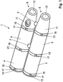
- Fig. 1 shows a pressure body 1 for an autonomous underwater vehicle or Autonomous Underwater Vehicle (AUV) consisting of two pressure vessels 5, which are connected to each other with a connection tunnel 7.
- Each of the pressure vessels 5 has in each case two cylindrical sections 9 and a frustoconical section 11. This streamlined arrangement reduces the resistance of the AUV in the water and thus provides greater energy efficiency.
- the ends of the pressure vessel 5 are closed by end caps 13, which allows faster access to the interior.
- the sections 9, 11 and the front of the end caps 13 are screwed together by clamping rings 15. For tightening the clamping rings 15 and for secure screwing of the sections 9, 11 and the front end cap 13, two clamping ring screws 17 are used for each clamping ring 15.
- Fig. 2 shows an overview of the AUV 18.
- the frustoconical portion 11 is connected to the drive 19.
- the battery blocks 21 are located in the front cylindrical portion 9 and are preferably spatially separated by insulating layers 22 from each other.
- the resulting in a thermal run through one of the batteries 21 strong temperature rise and caused by the outgassing of the battery 21 pressure increase should not damage or affect the pressure body 1 as far as possible. This is achieved by the dimensioning of the heat capacity of the pressure hull 1, which absorbs the resulting heat. This can limit the effects of thermal runaway on the continuous battery 21.
- components 23 in the interior 24 are also preferably protected.
- the components 23 may be, for example, measuring apparatus as well as sensors or cameras, but also headlights or seals are covered by this term.
- the pressure body 1 itself and its components is protected by the present invention, so that an explosion of the pressure hull 1 or a water ingress is prevented by damaged seals.
- the pressure body 1 has a first pressure relief valve 25 with a predefined response pressure.
- the first pressure relief valve 25 automatically prevents the emergence of overpressure in the interior 24 by gases occurring when passing through the battery 21.
- a second pressure relief valve 27 With a second pressure relief valve 27, a manual pressure relief is also possible. An explosion of the pressure hull 1 by an excessive internal pressure is counteracted.
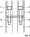
- Fig. 3 shows a plan view of a clamping ring gland, wherein the clamping rings 15 are screwed with clamping ring screws 17.
- the threaded insert 28 is lowered into the material of the clamping ring 15 to prevent protrusion of the clamping ring screws 17.
- a quick access to the components in the pressure vessels 5 is possible.
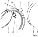
- Fig. 4 shows a detailed view of the connection tunnel 7 between the two pressure vessels 5.
- the pressure vessel 5 at two points - preferably at the central portion 9 and the rear portion 11 - connected by connecting tunnel 7.
- the connection tunnels 7 are each fastened by the inner sides of the pressure vessels 5 with connecting tunnel screws 29, which preferably consist of six hexagon screws.
- An O-ring (not shown) is used to seal between the connection tunnel 7 and the pressure vessel 5.
- the pressure vessel 5 are also pressure moderately connected to each other, so that a larger volume for receiving gas during outgassing of a battery 21 during thermal run is provided.
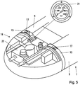
- Fig. 5 shows a detail view of the bow of the AUV 18.
- a pressure gauge 31 which can be read from outside the AUV 18. By the ability to read the pressure gauge 31 from the outside, a possible overpressure by outgassing a battery 21 can be detected early and thus appropriate safety and remedial measures are initiated.
- the pressure gauge 31 is connected to a pressure measuring device. The pressure is transmitted via a pressure line 33, which extends into the interior 24, to the pressure indicator 31. Alternatively, instead of a pressure line 33 and a pressure sensor can be used.
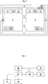
- Fig. 6 shows an overview of a part of the components included in the AUV 18.
- the pressure body 1 preferably consists of two pressure vessels 5, in each of which two battery blocks 21 are arranged. These are separated from one another by thermally insulating layers 22.
- the batteries 21 are not part of the unmanned underwater vehicle 18, but can be arranged in the interior 24 of the pressure hull 1.
- the batteries 21 are exchangeable with little effort, in particular after damage by a battery fire or otherwise damage by thermal runaway.
- the first pressure relief valve 25 and the second pressure relief valve 27 can discharge the pressure from the interior 24 of the pressure vessel 5. These provide a connection between the interior 24 of a pressure vessel 5 and the environment of the AUV 18 ago. Preferably, they are located near the area where the highest gas evolution can take place (e.g., near the batteries 21).
- a pressure measuring device 30 includes a sensor or a pressure line 33 in the interior 24 of the pressure hull 1. By means of the sensor or the pressure line 33, the prevailing pressure in the interior 24 of the pressure hull 1 is measured. The display of this resulting digital or analog data takes place by means of a pressure display 31, which is readable from outside the AUV 18.
- Fig. 7 shows a diagram illustrating the data management system.
- a microprocessor-controlled unit 39 monitors the current, voltage and temperature of the battery blocks 21 with a sensor 41 and compares the data collected thereby with a normal value library 43. If the measured data deviates too much from the normal values 43, the microprocessor-controlled unit 39 can directly do the Disconnect charger 45 and / or battery 21.
- the microprocessor-controlled unit 39 further communicates the collected data with a battery management system 47, which can also switch off the charger 45 and / or the battery 21 at critical values. Further, the battery management system 47 stores the data on a storage medium 49, preferably as an SD card is formed, and communicates this data to other, externally connected devices 51.
- Fig. 8 shows a flowchart with an overview of the method.
- the thermal run through 53a of one of the batteries 21 causes, inter alia, a rise in temperature 53b.
- This produced heat is absorbed by the high heat capacity of the pressure body 1 53c and thus limits the temperature and / or the temperature rise 53d in the interior 24 of the pressure body 1.
- the pressure body 1 is thus protected by this chain reaction against overheating 53e, wherein the pressure body 1 remains intact 54f.
- the outgassing of the battery 21 by the thermal runaway 53a results in a pressure increase 53g.
- the first or second pressure relief valve 25 27 of the pressure in the interior 24 of the pressure hull 1 is discharged 53 h, which causes a limitation of the pressure and or the pressure increase 53 i.
- the risk of explosion of the pressure hull 1 is thus reduced or prevented 53j. This also keeps the pressure body 1 intact 53f.
Landscapes
- Engineering & Computer Science (AREA)
- Chemical & Material Sciences (AREA)
- Combustion & Propulsion (AREA)
- General Engineering & Computer Science (AREA)
- Battery Mounting, Suspending (AREA)
- Secondary Cells (AREA)
Claims (10)
- Véhicule sous-marin autonome doté d'une coque haute pression (1) délimitant un espace intérieur (24), dans lequel la coque haute pression (1) est protégée contre la surchauffe, dans lequel la coque haute pression (1) présente un réservoir sous pression (5), dans lequel au moins une batterie est agencée dans le réservoir sous pression (5), caractérisé en ce qu'un matériau du réservoir sous pression (5) est constitué d'aluminium doté d'une conductivité thermique élevée et d'une capacité thermique élevée, et qu'une capacité thermique de la coque haute pression (1) soit choisie de telle sorte que lors d'un emballement thermique d'une ou de plusieurs batteries (21), qui sont agencées dans l'espace intérieur (24), une température de l'espace intérieur (24) s'élève au maximum de sorte que la coque haute pression (1) demeure intacte, dans lequel la coque haute pression (1) absorbe une chaleur dégagée lors de l'emballement thermique de la batterie (21), et qu'une conductivité thermique de la coque haute pression (1) soit choisie de telle sorte que la chaleur dégagée lors de l'emballement thermique de la batterie (21) ou des batteries (21) à l'intérieur de la coque haute pression (1) soit répartie et qu'ainsi l'on contrebalance l'apparition de foyers thermiques locaux.
- Véhicule sous-marin autonome selon la revendication 1, dans lequel plusieurs batteries (21) sont agencées dans l'espace intérieur (24), caractérisé en ce que la coque haute pression (1) présente plusieurs réservoirs sous pression (5), qui sont reliés l'un à l'autre en fonction de la pression afin de compenser la pression et chacun présentant au moins une des batteries (21), dans lequel le matériau d'au moins un réservoir sous pression est constitué d'aluminium.
- Véhicule sous-marin autonome selon l'une quelconque des revendications précédentes, caractérisé en ce que la coque haute pression (1) présente une ou plusieurs premières soupapes de sûreté (25) dotées d'une pression de déclenchement prédéfinie afin de libérer les gaz générés lors de l'emballement thermique de la batterie (21) ou des batteries (21).
- Véhicule sous-marin autonome selon l'une quelconque des revendications précédentes, caractérisé en ce que la coque haute pression (1) présente une ou plusieurs secondes soupapes de sûreté (27) actionnables manuellement afin de libérer les gaz générés lors de l'emballement thermique de la batterie (21) ou des batteries (21).
- Véhicule sous-marin autonome selon l'une quelconque des revendications précédentes, caractérisé en ce que la coque haute pression (1) présente un dispositif de mesure de pression (30) à l'aide duquel la pression régnant dans l'espace intérieur (24) de la coque haute pression (1) est mesurable, dans lequel le dispositif de mesure de pression (30) présente un affichage de la pression (31) pour indiquer la pression mesurée, qui peut être consulté depuis l'extérieur du véhicule sous-marin autonome (18).
- Procédé de protection contre la surchauffe d'une coque haute pression (1) délimitant un espace intérieur (24) d'un véhicule sous-marin autonome (18) selon l'une quelconque des revendications 1 à 5, caractérisé en ce que lors de l'emballement thermique (53a) d'une ou de plusieurs batteries (21), qui sont agencées dans l'espace intérieur (24), une température de l'espace intérieur s'élève, en raison d'une capacité thermique de la coque haute pression (1), au maximum de sorte que la coque haute pression (1) demeure intacte (53e), dans lequel la coque haute pression (1) absorbe une chaleur dégagée lors de l'emballement thermique (53a) de la batterie (21), et que la coque haute pression (1) répartit, grâce à sa conductivité thermique, la chaleur générée à l'intérieur de la coque haute pression (1), de sorte que l'apparition de foyers thermiques locaux s'en trouve contrebalancée.
- Procédé selon la revendication 6, dans lequel plusieurs batteries sont agencées dans l'espace intérieur (24), caractérisé en ce qu'une compensation de pression s'effectue entre plusieurs réservoirs sous pression (5) de la coque haute pression (1), qui sont reliés entre eux en fonction de la pression et qui présentent chacun au moins une des batteries (21).
- Procédé selon l'une quelconque des revendications 6 à 7, caractérisé en ce qu'une ou plusieurs premières soupapes de sûreté (25) de la coque haute pression (1) dotées d'une pression de déclenchement prédéfinie libèrent (53i) les gaz générés lors de l'emballement (53a) de la batterie (21) ou des batteries (21).
- Procédé selon l'une quelconque des revendications 6 à 8, caractérisé en ce qu'une ou plusieurs secondes soupapes de sûreté (27) actionnables manuellement libèrent (53i) les gaz générés lors de l'emballement (53a) de la batterie (21) ou des batteries (21).
- Procédé selon l'une quelconque des revendications 6 à 9, caractérisé en ce qu'une pression dans l'espace intérieur (24) de la coque haute pression (1) est mesurée avec un dispositif de mesure de pression (30), dans lequel un affichage de la pression (31) du dispositif de mesure de pression (30) consultable depuis l'extérieur du véhicule sous-marin autonome (18) indique la pression mesurée à l'extérieur du véhicule sous-marin autonome (18).
Applications Claiming Priority (2)
| Application Number | Priority Date | Filing Date | Title |
|---|---|---|---|
| DE102013105592.3A DE102013105592A1 (de) | 2013-05-30 | 2013-05-30 | Unbemanntes Unterwasserfahrzeug mit einem Druckkörper und Verfahren hierzu |
| PCT/DE2014/100142 WO2014190972A1 (fr) | 2013-05-30 | 2014-04-25 | Véhicule sous-marin autonome pourvu d'une coque de haute pression, et procédé correspondant |
Publications (2)
| Publication Number | Publication Date |
|---|---|
| EP3004792A1 EP3004792A1 (fr) | 2016-04-13 |
| EP3004792B1 true EP3004792B1 (fr) | 2017-12-27 |
Family
ID=50896127
Family Applications (1)
| Application Number | Title | Priority Date | Filing Date |
|---|---|---|---|
| EP14728419.4A Not-in-force EP3004792B1 (fr) | 2013-05-30 | 2014-04-25 | Véhicule sous-marin autonome pourvu d'une coque de haute pression, et procédé correspondant |
Country Status (4)
| Country | Link |
|---|---|
| EP (1) | EP3004792B1 (fr) |
| DE (1) | DE102013105592A1 (fr) |
| NO (1) | NO3087070T3 (fr) |
| WO (1) | WO2014190972A1 (fr) |
Families Citing this family (2)
| Publication number | Priority date | Publication date | Assignee | Title |
|---|---|---|---|---|
| CN109901444A (zh) * | 2017-12-08 | 2019-06-18 | 中国科学院沈阳自动化研究所 | 水下机器人舱内温度、电流、烟雾及图像监视装置及方法 |
| CN115006757A (zh) * | 2022-04-11 | 2022-09-06 | 北京机电工程研究所 | 一种锂电池灭火系统、水下装置及锂电池灭火方法 |
Citations (1)
| Publication number | Priority date | Publication date | Assignee | Title |
|---|---|---|---|---|
| WO2011089182A1 (fr) * | 2010-01-20 | 2011-07-28 | Robert Bosch Gmbh | Ensemble batterie à plaque d'accumulation de chaleur |
Family Cites Families (9)
| Publication number | Priority date | Publication date | Assignee | Title |
|---|---|---|---|---|
| CH598988A5 (en) * | 1976-01-20 | 1978-05-12 | Jacques Piccard | Submarine for under-water pipe laying |
| DE19537683C2 (de) * | 1995-10-10 | 1998-04-16 | Stn Atlas Elektronik Gmbh | Außenluftunabhängiger Speicher für elektrische Energie |
| DE10106521C1 (de) * | 2001-02-13 | 2002-07-11 | Stn Atlas Elektronik Gmbh | Unterwasserlaufkörper |
| DE102004045537B3 (de) * | 2004-09-20 | 2006-03-02 | Atlas Elektronik Gmbh | Kühlvorrichtung |
| WO2007007340A2 (fr) * | 2005-07-13 | 2007-01-18 | O.D.F. Optronics Ltd. | Systeme d'observation |
| DE102006010063B4 (de) * | 2006-03-04 | 2021-09-02 | Bbp Kunststoffwerk Marbach Baier Gmbh | Kühleinrichtung für Batterien |
| IN2012DN02257A (fr) * | 2009-09-15 | 2015-08-21 | Bae Systems Plc | |
| EP2576342A4 (fr) * | 2010-05-26 | 2014-08-20 | Aerovironment Inc | Système de véhicule reconfigurable fonctionnant sur batterie |
| US9267993B2 (en) * | 2012-05-23 | 2016-02-23 | Lawrence Livermore National Security, Llc | Battery management system with distributed wireless sensors |
-
2013
- 2013-05-30 DE DE102013105592.3A patent/DE102013105592A1/de not_active Withdrawn
-
2014
- 2014-04-25 WO PCT/DE2014/100142 patent/WO2014190972A1/fr not_active Ceased
- 2014-04-25 EP EP14728419.4A patent/EP3004792B1/fr not_active Not-in-force
- 2014-12-18 NO NO14824711A patent/NO3087070T3/no unknown
Patent Citations (1)
| Publication number | Priority date | Publication date | Assignee | Title |
|---|---|---|---|---|
| WO2011089182A1 (fr) * | 2010-01-20 | 2011-07-28 | Robert Bosch Gmbh | Ensemble batterie à plaque d'accumulation de chaleur |
Also Published As
| Publication number | Publication date |
|---|---|
| EP3004792A1 (fr) | 2016-04-13 |
| DE102013105592A1 (de) | 2014-12-04 |
| NO3087070T3 (fr) | 2018-04-07 |
| WO2014190972A1 (fr) | 2014-12-04 |
Similar Documents
| Publication | Publication Date | Title |
|---|---|---|
| EP2290729B1 (fr) | Accumulateur d' énergie électrique avec une système de compensation de volume | |
| DE102009046496A1 (de) | Notkühlverfahren und Notkühlsystem | |
| DE102011016527A1 (de) | Vorrichtung und Verfahren zur Dichtheitsüberprüfung eines elektrochemischen Energiespeichers | |
| EP4052322A2 (fr) | Module de batterie avec surveillance de l'emballement thermique d'éléments individuels | |
| DE102010013017A1 (de) | Sicherungseinrichtung für Batterien bzw. Batterieanordnungen | |
| DE102012213054A1 (de) | Transportbehälter für eine defekte Lithium-Ionen-Batterie | |
| DE102014200997A1 (de) | Batterie und Verfahren zur Überwachung einer Batterie sowie Batteriesystem mit der Batterie | |
| DE102018211629A1 (de) | Löschsystem für eine Hochvoltbatterie eines Kraftfahrzeugs und Kraftfahrzeug mit einem Löschsystem für eine Hochvoltbatterie | |
| EP3245680B1 (fr) | Dispositif d'alimentation en énergie sous-marin autonome | |
| EP3004792B1 (fr) | Véhicule sous-marin autonome pourvu d'une coque de haute pression, et procédé correspondant | |
| DE102012217383A1 (de) | System zur Entgasung von Akkumulatoren | |
| DE102021005751A1 (de) | Batteriesystem | |
| DE102012021095A1 (de) | Akkumulator für ein Fahrzeug mit Notlöscheinrichtung | |
| EP4104906A1 (fr) | Dépôt et agencement de stockage d'un véhicule | |
| DE102021103517A1 (de) | System für einen Energiespeicher eines Fahrzeugs und Fahrzeug mit einem solchen System | |
| DE102011107824A1 (de) | Einrichtung und Verfahren zum Betreiben eines unbemannten Unterwasserfahrzeugs sowie Unterwasserfahrzeug mit der Einrichtung | |
| DE102008006920B4 (de) | Sicherer elektrischer Speicher | |
| EP2489588A1 (fr) | Véhicule sous-marin inhabité, corps de remplacement pouvant être fixé dessus, système doté d'un véhicule sous-marin inhabité et du corps de remplacement, ainsi que procédé de fonctionnement d'un véhicule sous-marin inhabité | |
| DE202016001797U1 (de) | Transportvorrichtung für Lithiumbatterien in einem Flugzeug | |
| DE102012213726A1 (de) | Überwachungsvorrichtung sowie Verfahren zur Überwachung einer Batterie | |
| DE102013210154B4 (de) | Vorrichtung zur Erhöhung der Sicherheit beim Gebrauch von Batteriesystemen | |
| DE102016213364A1 (de) | Fahrzeug mit einem Hochvoltspeicher | |
| DE3826423C1 (en) | Safety device for an electrochemical cell and method | |
| EP3602651A1 (fr) | Procédé pour produire un accumulateur d'énergie et accumulateur d'énergie | |
| DE102013022632B3 (de) | Vorrichtung zur Erhöhung der Sicherheit beim Gebrauch von Batteriesystemen |
Legal Events
| Date | Code | Title | Description |
|---|---|---|---|
| PUAI | Public reference made under article 153(3) epc to a published international application that has entered the european phase |
Free format text: ORIGINAL CODE: 0009012 |
|
| 17P | Request for examination filed |
Effective date: 20151007 |
|
| AK | Designated contracting states |
Kind code of ref document: A1 Designated state(s): AL AT BE BG CH CY CZ DE DK EE ES FI FR GB GR HR HU IE IS IT LI LT LU LV MC MK MT NL NO PL PT RO RS SE SI SK SM TR |
|
| AX | Request for extension of the european patent |
Extension state: BA ME |
|
| RIN1 | Information on inventor provided before grant (corrected) |
Inventor name: WALTL, BERND |
|
| DAX | Request for extension of the european patent (deleted) | ||
| 17Q | First examination report despatched |
Effective date: 20161209 |
|
| REG | Reference to a national code |
Ref country code: DE Ref legal event code: R079 Ref document number: 502014006738 Country of ref document: DE Free format text: PREVIOUS MAIN CLASS: F42B0019240000 Ipc: B63G0008000000 |
|
| RIC1 | Information provided on ipc code assigned before grant |
Ipc: B63G 8/00 20060101AFI20170613BHEP |
|
| GRAP | Despatch of communication of intention to grant a patent |
Free format text: ORIGINAL CODE: EPIDOSNIGR1 |
|
| INTG | Intention to grant announced |
Effective date: 20170721 |
|
| GRAA | (expected) grant |
Free format text: ORIGINAL CODE: 0009210 |
|
| GRAS | Grant fee paid |
Free format text: ORIGINAL CODE: EPIDOSNIGR3 |
|
| AK | Designated contracting states |
Kind code of ref document: B1 Designated state(s): AL AT BE BG CH CY CZ DE DK EE ES FI FR GB GR HR HU IE IS IT LI LT LU LV MC MK MT NL NO PL PT RO RS SE SI SK SM TR |
|
| REG | Reference to a national code |
Ref country code: GB Ref legal event code: FG4D Free format text: NOT ENGLISH |
|
| REG | Reference to a national code |
Ref country code: CH Ref legal event code: EP |
|
| REG | Reference to a national code |
Ref country code: AT Ref legal event code: REF Ref document number: 958029 Country of ref document: AT Kind code of ref document: T Effective date: 20180115 |
|
| REG | Reference to a national code |
Ref country code: IE Ref legal event code: FG4D Free format text: LANGUAGE OF EP DOCUMENT: GERMAN |
|
| REG | Reference to a national code |
Ref country code: DE Ref legal event code: R096 Ref document number: 502014006738 Country of ref document: DE |
|
| REG | Reference to a national code |
Ref country code: SE Ref legal event code: TRGR |
|
| REG | Reference to a national code |
Ref country code: FR Ref legal event code: PLFP Year of fee payment: 5 |
|
| PG25 | Lapsed in a contracting state [announced via postgrant information from national office to epo] |
Ref country code: LT Free format text: LAPSE BECAUSE OF FAILURE TO SUBMIT A TRANSLATION OF THE DESCRIPTION OR TO PAY THE FEE WITHIN THE PRESCRIBED TIME-LIMIT Effective date: 20171227 Ref country code: FI Free format text: LAPSE BECAUSE OF FAILURE TO SUBMIT A TRANSLATION OF THE DESCRIPTION OR TO PAY THE FEE WITHIN THE PRESCRIBED TIME-LIMIT Effective date: 20171227 |
|
| REG | Reference to a national code |
Ref country code: NL Ref legal event code: MP Effective date: 20171227 |
|
| REG | Reference to a national code |
Ref country code: LT Ref legal event code: MG4D |
|
| PG25 | Lapsed in a contracting state [announced via postgrant information from national office to epo] |
Ref country code: RS Free format text: LAPSE BECAUSE OF FAILURE TO SUBMIT A TRANSLATION OF THE DESCRIPTION OR TO PAY THE FEE WITHIN THE PRESCRIBED TIME-LIMIT Effective date: 20171227 Ref country code: LV Free format text: LAPSE BECAUSE OF FAILURE TO SUBMIT A TRANSLATION OF THE DESCRIPTION OR TO PAY THE FEE WITHIN THE PRESCRIBED TIME-LIMIT Effective date: 20171227 Ref country code: GR Free format text: LAPSE BECAUSE OF FAILURE TO SUBMIT A TRANSLATION OF THE DESCRIPTION OR TO PAY THE FEE WITHIN THE PRESCRIBED TIME-LIMIT Effective date: 20180328 Ref country code: BG Free format text: LAPSE BECAUSE OF FAILURE TO SUBMIT A TRANSLATION OF THE DESCRIPTION OR TO PAY THE FEE WITHIN THE PRESCRIBED TIME-LIMIT Effective date: 20180327 Ref country code: HR Free format text: LAPSE BECAUSE OF FAILURE TO SUBMIT A TRANSLATION OF THE DESCRIPTION OR TO PAY THE FEE WITHIN THE PRESCRIBED TIME-LIMIT Effective date: 20171227 |
|
| REG | Reference to a national code |
Ref country code: NO Ref legal event code: T2 Effective date: 20171227 |
|
| PG25 | Lapsed in a contracting state [announced via postgrant information from national office to epo] |
Ref country code: NL Free format text: LAPSE BECAUSE OF FAILURE TO SUBMIT A TRANSLATION OF THE DESCRIPTION OR TO PAY THE FEE WITHIN THE PRESCRIBED TIME-LIMIT Effective date: 20171227 |
|
| PG25 | Lapsed in a contracting state [announced via postgrant information from national office to epo] |
Ref country code: CY Free format text: LAPSE BECAUSE OF FAILURE TO SUBMIT A TRANSLATION OF THE DESCRIPTION OR TO PAY THE FEE WITHIN THE PRESCRIBED TIME-LIMIT Effective date: 20171227 Ref country code: EE Free format text: LAPSE BECAUSE OF FAILURE TO SUBMIT A TRANSLATION OF THE DESCRIPTION OR TO PAY THE FEE WITHIN THE PRESCRIBED TIME-LIMIT Effective date: 20171227 Ref country code: CZ Free format text: LAPSE BECAUSE OF FAILURE TO SUBMIT A TRANSLATION OF THE DESCRIPTION OR TO PAY THE FEE WITHIN THE PRESCRIBED TIME-LIMIT Effective date: 20171227 Ref country code: ES Free format text: LAPSE BECAUSE OF FAILURE TO SUBMIT A TRANSLATION OF THE DESCRIPTION OR TO PAY THE FEE WITHIN THE PRESCRIBED TIME-LIMIT Effective date: 20171227 Ref country code: SK Free format text: LAPSE BECAUSE OF FAILURE TO SUBMIT A TRANSLATION OF THE DESCRIPTION OR TO PAY THE FEE WITHIN THE PRESCRIBED TIME-LIMIT Effective date: 20171227 |
|
| RAP2 | Party data changed (patent owner data changed or rights of a patent transferred) |
Owner name: ATLAS ELEKTRONIK GMBH |
|
| PG25 | Lapsed in a contracting state [announced via postgrant information from national office to epo] |
Ref country code: SM Free format text: LAPSE BECAUSE OF FAILURE TO SUBMIT A TRANSLATION OF THE DESCRIPTION OR TO PAY THE FEE WITHIN THE PRESCRIBED TIME-LIMIT Effective date: 20171227 Ref country code: IT Free format text: LAPSE BECAUSE OF FAILURE TO SUBMIT A TRANSLATION OF THE DESCRIPTION OR TO PAY THE FEE WITHIN THE PRESCRIBED TIME-LIMIT Effective date: 20171227 Ref country code: RO Free format text: LAPSE BECAUSE OF FAILURE TO SUBMIT A TRANSLATION OF THE DESCRIPTION OR TO PAY THE FEE WITHIN THE PRESCRIBED TIME-LIMIT Effective date: 20171227 Ref country code: IS Free format text: LAPSE BECAUSE OF FAILURE TO SUBMIT A TRANSLATION OF THE DESCRIPTION OR TO PAY THE FEE WITHIN THE PRESCRIBED TIME-LIMIT Effective date: 20180427 Ref country code: PL Free format text: LAPSE BECAUSE OF FAILURE TO SUBMIT A TRANSLATION OF THE DESCRIPTION OR TO PAY THE FEE WITHIN THE PRESCRIBED TIME-LIMIT Effective date: 20171227 |
|
| PG25 | Lapsed in a contracting state [announced via postgrant information from national office to epo] |
Ref country code: MT Free format text: LAPSE BECAUSE OF FAILURE TO SUBMIT A TRANSLATION OF THE DESCRIPTION OR TO PAY THE FEE WITHIN THE PRESCRIBED TIME-LIMIT Effective date: 20171227 |
|
| REG | Reference to a national code |
Ref country code: DE Ref legal event code: R097 Ref document number: 502014006738 Country of ref document: DE |
|
| PLBE | No opposition filed within time limit |
Free format text: ORIGINAL CODE: 0009261 |
|
| STAA | Information on the status of an ep patent application or granted ep patent |
Free format text: STATUS: NO OPPOSITION FILED WITHIN TIME LIMIT |
|
| PG25 | Lapsed in a contracting state [announced via postgrant information from national office to epo] |
Ref country code: DK Free format text: LAPSE BECAUSE OF FAILURE TO SUBMIT A TRANSLATION OF THE DESCRIPTION OR TO PAY THE FEE WITHIN THE PRESCRIBED TIME-LIMIT Effective date: 20171227 Ref country code: MC Free format text: LAPSE BECAUSE OF FAILURE TO SUBMIT A TRANSLATION OF THE DESCRIPTION OR TO PAY THE FEE WITHIN THE PRESCRIBED TIME-LIMIT Effective date: 20171227 |
|
| REG | Reference to a national code |
Ref country code: CH Ref legal event code: PL |
|
| 26N | No opposition filed |
Effective date: 20180928 |
|
| REG | Reference to a national code |
Ref country code: BE Ref legal event code: MM Effective date: 20180430 |
|
| REG | Reference to a national code |
Ref country code: IE Ref legal event code: MM4A |
|
| PG25 | Lapsed in a contracting state [announced via postgrant information from national office to epo] |
Ref country code: LU Free format text: LAPSE BECAUSE OF NON-PAYMENT OF DUE FEES Effective date: 20180425 |
|
| PG25 | Lapsed in a contracting state [announced via postgrant information from national office to epo] |
Ref country code: LI Free format text: LAPSE BECAUSE OF NON-PAYMENT OF DUE FEES Effective date: 20180430 Ref country code: CH Free format text: LAPSE BECAUSE OF NON-PAYMENT OF DUE FEES Effective date: 20180430 Ref country code: SI Free format text: LAPSE BECAUSE OF FAILURE TO SUBMIT A TRANSLATION OF THE DESCRIPTION OR TO PAY THE FEE WITHIN THE PRESCRIBED TIME-LIMIT Effective date: 20171227 Ref country code: BE Free format text: LAPSE BECAUSE OF NON-PAYMENT OF DUE FEES Effective date: 20180430 |
|
| PG25 | Lapsed in a contracting state [announced via postgrant information from national office to epo] |
Ref country code: IE Free format text: LAPSE BECAUSE OF NON-PAYMENT OF DUE FEES Effective date: 20180425 |
|
| PG25 | Lapsed in a contracting state [announced via postgrant information from national office to epo] |
Ref country code: TR Free format text: LAPSE BECAUSE OF FAILURE TO SUBMIT A TRANSLATION OF THE DESCRIPTION OR TO PAY THE FEE WITHIN THE PRESCRIBED TIME-LIMIT Effective date: 20171227 |
|
| PG25 | Lapsed in a contracting state [announced via postgrant information from national office to epo] |
Ref country code: PT Free format text: LAPSE BECAUSE OF FAILURE TO SUBMIT A TRANSLATION OF THE DESCRIPTION OR TO PAY THE FEE WITHIN THE PRESCRIBED TIME-LIMIT Effective date: 20171227 |
|
| PG25 | Lapsed in a contracting state [announced via postgrant information from national office to epo] |
Ref country code: MK Free format text: LAPSE BECAUSE OF NON-PAYMENT OF DUE FEES Effective date: 20171227 Ref country code: HU Free format text: LAPSE BECAUSE OF FAILURE TO SUBMIT A TRANSLATION OF THE DESCRIPTION OR TO PAY THE FEE WITHIN THE PRESCRIBED TIME-LIMIT; INVALID AB INITIO Effective date: 20140425 |
|
| PG25 | Lapsed in a contracting state [announced via postgrant information from national office to epo] |
Ref country code: AL Free format text: LAPSE BECAUSE OF FAILURE TO SUBMIT A TRANSLATION OF THE DESCRIPTION OR TO PAY THE FEE WITHIN THE PRESCRIBED TIME-LIMIT Effective date: 20171227 |
|
| PGFP | Annual fee paid to national office [announced via postgrant information from national office to epo] |
Ref country code: FR Payment date: 20200420 Year of fee payment: 7 Ref country code: NO Payment date: 20200422 Year of fee payment: 7 Ref country code: DE Payment date: 20200420 Year of fee payment: 7 |
|
| REG | Reference to a national code |
Ref country code: AT Ref legal event code: MM01 Ref document number: 958029 Country of ref document: AT Kind code of ref document: T Effective date: 20190425 |
|
| PGFP | Annual fee paid to national office [announced via postgrant information from national office to epo] |
Ref country code: GB Payment date: 20200427 Year of fee payment: 7 Ref country code: SE Payment date: 20200427 Year of fee payment: 7 |
|
| PG25 | Lapsed in a contracting state [announced via postgrant information from national office to epo] |
Ref country code: AT Free format text: LAPSE BECAUSE OF NON-PAYMENT OF DUE FEES Effective date: 20190425 |
|
| REG | Reference to a national code |
Ref country code: DE Ref legal event code: R119 Ref document number: 502014006738 Country of ref document: DE |
|
| REG | Reference to a national code |
Ref country code: NO Ref legal event code: MMEP |
|
| REG | Reference to a national code |
Ref country code: SE Ref legal event code: EUG |
|
| GBPC | Gb: european patent ceased through non-payment of renewal fee |
Effective date: 20210425 |
|
| PG25 | Lapsed in a contracting state [announced via postgrant information from national office to epo] |
Ref country code: NO Free format text: LAPSE BECAUSE OF NON-PAYMENT OF DUE FEES Effective date: 20210430 Ref country code: SE Free format text: LAPSE BECAUSE OF NON-PAYMENT OF DUE FEES Effective date: 20210426 Ref country code: FR Free format text: LAPSE BECAUSE OF NON-PAYMENT OF DUE FEES Effective date: 20210430 Ref country code: GB Free format text: LAPSE BECAUSE OF NON-PAYMENT OF DUE FEES Effective date: 20210425 Ref country code: DE Free format text: LAPSE BECAUSE OF NON-PAYMENT OF DUE FEES Effective date: 20211103 |