EP3003185B1 - Instrument zum einsetzen eines dornfortsatzimplantats - Google Patents
Instrument zum einsetzen eines dornfortsatzimplantats Download PDFInfo
- Publication number
- EP3003185B1 EP3003185B1 EP14804610.5A EP14804610A EP3003185B1 EP 3003185 B1 EP3003185 B1 EP 3003185B1 EP 14804610 A EP14804610 A EP 14804610A EP 3003185 B1 EP3003185 B1 EP 3003185B1
- Authority
- EP
- European Patent Office
- Prior art keywords
- implant
- plunger
- insertion instrument
- main body
- spike cap
- Prior art date
- Legal status (The legal status is an assumption and is not a legal conclusion. Google has not performed a legal analysis and makes no representation as to the accuracy of the status listed.)
- Active
Links
Images


Classifications
-
- A—HUMAN NECESSITIES
- A61—MEDICAL OR VETERINARY SCIENCE; HYGIENE
- A61B—DIAGNOSIS; SURGERY; IDENTIFICATION
- A61B17/00—Surgical instruments, devices or methods
- A61B17/56—Surgical instruments or methods for treatment of bones or joints; Devices specially adapted therefor
- A61B17/58—Surgical instruments or methods for treatment of bones or joints; Devices specially adapted therefor for osteosynthesis, e.g. bone plates, screws or setting implements
- A61B17/68—Internal fixation devices, including fasteners and spinal fixators, even if a part thereof projects from the skin
- A61B17/70—Spinal positioners or stabilisers, e.g. stabilisers comprising fluid filler in an implant
- A61B17/7062—Devices acting on, attached to, or simulating the effect of, vertebral processes, vertebral facets or ribs ; Tools for such devices
- A61B17/7065—Devices with changeable shape, e.g. collapsible or having retractable arms to aid implantation; Tools therefor
-
- A—HUMAN NECESSITIES
- A61—MEDICAL OR VETERINARY SCIENCE; HYGIENE
- A61B—DIAGNOSIS; SURGERY; IDENTIFICATION
- A61B17/00—Surgical instruments, devices or methods
- A61B17/56—Surgical instruments or methods for treatment of bones or joints; Devices specially adapted therefor
- A61B17/58—Surgical instruments or methods for treatment of bones or joints; Devices specially adapted therefor for osteosynthesis, e.g. bone plates, screws or setting implements
- A61B17/68—Internal fixation devices, including fasteners and spinal fixators, even if a part thereof projects from the skin
- A61B17/70—Spinal positioners or stabilisers, e.g. stabilisers comprising fluid filler in an implant
- A61B17/7062—Devices acting on, attached to, or simulating the effect of, vertebral processes, vertebral facets or ribs ; Tools for such devices
-
- A—HUMAN NECESSITIES
- A61—MEDICAL OR VETERINARY SCIENCE; HYGIENE
- A61B—DIAGNOSIS; SURGERY; IDENTIFICATION
- A61B17/00—Surgical instruments, devices or methods
- A61B17/56—Surgical instruments or methods for treatment of bones or joints; Devices specially adapted therefor
- A61B17/58—Surgical instruments or methods for treatment of bones or joints; Devices specially adapted therefor for osteosynthesis, e.g. bone plates, screws or setting implements
- A61B17/68—Internal fixation devices, including fasteners and spinal fixators, even if a part thereof projects from the skin
- A61B17/70—Spinal positioners or stabilisers, e.g. stabilisers comprising fluid filler in an implant
- A61B17/7074—Tools specially adapted for spinal fixation operations other than for bone removal or filler handling
-
- A—HUMAN NECESSITIES
- A61—MEDICAL OR VETERINARY SCIENCE; HYGIENE
- A61B—DIAGNOSIS; SURGERY; IDENTIFICATION
- A61B17/00—Surgical instruments, devices or methods
- A61B17/56—Surgical instruments or methods for treatment of bones or joints; Devices specially adapted therefor
- A61B17/58—Surgical instruments or methods for treatment of bones or joints; Devices specially adapted therefor for osteosynthesis, e.g. bone plates, screws or setting implements
- A61B17/68—Internal fixation devices, including fasteners and spinal fixators, even if a part thereof projects from the skin
- A61B17/84—Fasteners therefor or fasteners being internal fixation devices
- A61B17/844—Fasteners therefor or fasteners being internal fixation devices with expandable anchors or anchors having movable parts
-
- A—HUMAN NECESSITIES
- A61—MEDICAL OR VETERINARY SCIENCE; HYGIENE
- A61B—DIAGNOSIS; SURGERY; IDENTIFICATION
- A61B17/00—Surgical instruments, devices or methods
- A61B17/56—Surgical instruments or methods for treatment of bones or joints; Devices specially adapted therefor
- A61B17/58—Surgical instruments or methods for treatment of bones or joints; Devices specially adapted therefor for osteosynthesis, e.g. bone plates, screws or setting implements
- A61B17/88—Osteosynthesis instruments; Methods or means for implanting or extracting internal or external fixation devices
- A61B17/8875—Screwdrivers, spanners or wrenches
- A61B17/8877—Screwdrivers, spanners or wrenches characterised by the cross-section of the driver bit
- A61B17/8883—Screwdrivers, spanners or wrenches characterised by the cross-section of the driver bit the driver bit acting on the periphery of the screw head
-
- A—HUMAN NECESSITIES
- A61—MEDICAL OR VETERINARY SCIENCE; HYGIENE
- A61B—DIAGNOSIS; SURGERY; IDENTIFICATION
- A61B17/00—Surgical instruments, devices or methods
- A61B17/56—Surgical instruments or methods for treatment of bones or joints; Devices specially adapted therefor
- A61B17/58—Surgical instruments or methods for treatment of bones or joints; Devices specially adapted therefor for osteosynthesis, e.g. bone plates, screws or setting implements
- A61B17/88—Osteosynthesis instruments; Methods or means for implanting or extracting internal or external fixation devices
- A61B17/8875—Screwdrivers, spanners or wrenches
- A61B17/8886—Screwdrivers, spanners or wrenches holding the screw head
- A61B17/8888—Screwdrivers, spanners or wrenches holding the screw head at its central region
-
- A—HUMAN NECESSITIES
- A61—MEDICAL OR VETERINARY SCIENCE; HYGIENE
- A61B—DIAGNOSIS; SURGERY; IDENTIFICATION
- A61B17/00—Surgical instruments, devices or methods
- A61B17/56—Surgical instruments or methods for treatment of bones or joints; Devices specially adapted therefor
- A61B17/58—Surgical instruments or methods for treatment of bones or joints; Devices specially adapted therefor for osteosynthesis, e.g. bone plates, screws or setting implements
- A61B17/88—Osteosynthesis instruments; Methods or means for implanting or extracting internal or external fixation devices
- A61B17/8875—Screwdrivers, spanners or wrenches
- A61B17/8886—Screwdrivers, spanners or wrenches holding the screw head
- A61B17/8891—Screwdrivers, spanners or wrenches holding the screw head at its periphery
-
- A—HUMAN NECESSITIES
- A61—MEDICAL OR VETERINARY SCIENCE; HYGIENE
- A61B—DIAGNOSIS; SURGERY; IDENTIFICATION
- A61B17/00—Surgical instruments, devices or methods
- A61B2017/00526—Methods of manufacturing
Definitions
- the spine consists of a column of twenty-four vertebrae that extend from the skull to the hips. Discs of soft tissue are disposed between adjacent vertebrae. The vertebrae provide support for the head and body, while the discs act as cushions. In addition, the spine encloses and protects the spinal cord, defining a bony channel around the spinal cord, called the spinal canal. There is normally a space between the spinal cord and the borders of the spinal canal so that the spinal cord and the nerves associated therewith are not pinched.
- Non-surgical treatments for spinal stenosis include non-steroidal anti-inflammatory drugs to reduce the swelling and pain, and corticosteroid injections to reduce swelling and treat acute pain. While some patients may experience relief from symptoms of spinal stenosis with such treatments, many do not, and thus turn to surgical treatment.
- Some surgical procedures for treating spinal stenosis are decompressive laminectomy and interspinous process decompression (IPD).
- a well-known implant used for performing IPD surgery is the X-STOP® device, which is described in U.S. Patent No. 6,419,676 .
- Another interspinous process implant placed in a minimally invasive surgical procedure is disclosed in U.S. Patent Application Publication 2008/0243250 .
- Still another interspinous process implant placed in a minimally invasive surgical procedure is disclosed in U.S. Patent Application Publication 2010/0234889 .
- One aspect of effective insertion of these implants is to provide a low profile instrument for deploying the implant. Often, the insertion instrument has several moving parts. Because of the cost of the insertion instruments, the instruments are re-used many times.
- US 2010/0057130 A1 discloses a conical interspinous apparatus including a distractor comprising an insertion portion and a central engagement groove, the insertion portion having a conical shape which tapers to a tip and is adapted to enable passage of the distractor between two spinous processes of vertebrae, and the central engagement groove is adapted to secure the distractor between the two spinous processes such that the two spinous processes rest in the central engagement groove.
- the conical interspinous apparatus includes a stabilizer which is adapted to be deployed from within the distractor to secure the two spinous processes within the central engagement groove and an insertion driver detachably coupled to a rear portion of the distractor.
- a guide wire having a pointed tip, aids in the insertion of the distractor between the two spinous processes and is configured to guide the insertion of the distractor.
- CA 2 751 750 A1 discloses an interspinous process implant having deployable engagement arms.
- the implant includes an elongated body portion dimensioned and configured for percutaneous introduction into a target interspinous process space, at which interspinous distraction and/or spinal fusion are desired.
- the body portion can include a threaded outer surface, or alternatively a smooth surface.
- the body portion can include one or more interior cavities, and can include deployable engagement members adapted and configured to move in tandem between a stowed position retracted within the interior cavity of the body portion and a deployed position extended from the interior cavity of the body for engaging adjacent spinous processes.
- An internal drive assembly for selectively moving the engagement members from the stowed position to the deployed position can be provided, as can a elements for locking the engagement members in a deployed position.
- WO 2010/025408 A2 discloses a bone-derived interspinous spacer for implantation into an interspinous space located between spinous process of adjacent vertebrae.
- the spacer preferably includes a body, a core and a plurality of dep lovable retainers.
- the body may be operatively associated with the plurality of deployable retainers.
- the plurality of retainers is deployed so that they prevent migration of the spacer.
- the core is preferably sized and configured to be inserted and/or moved into operatively engagement with the body to deploy the plurality of retainers.
- the subject technology is directed to an insertion device for a spinal implant, wherein the spinal implant includes: a) an elongated body to function as a spacer placed in a target interspinous process space between two adjacent spinous processes, wherein the body defines an interior and a proximal internal recess for access to the interior, the proximal internal recess forming a transverse groove; b) a distal anchor that is at least partially threaded and has opposing radially deployable blades mounted for rotation about a pin transversely mounted in the interior; c) a proximal anchor including a spike cap mounted to slide along the body and a drive nut mounted for longitudinal movement along the body between a first position spaced apart from the distal anchor and a second position relatively closer to the distal anchor to thereby compress the two adjacent spinous processes between the spike cap and the distal anchor; and d) an actuation plunger slidably inside the interior for moving the blades from a stowed/insertion position to
- the insertion device includes an elongated main body having a distal locking portion for coupling to the implant and a proximal handle portion.
- the main body defines a central passage and the distal locking portion has outer ridges.
- the at least one slot allows at least one of the outer ridges to flex radially inward.
- a plunger slides in the central passage for movement between an unlocked position for mounting the implant on the distal locking portion, a locked position within the slot for locking the implant on the distal locking portion, and an insertion instrument deployed position for deploying the actuation plunger to move the blades from the stowed position to the deployed position.
- a spike cap drive rotatably mounts on the main body having a socket end for engaging the drive nut to, in turn, move the spike cap.
- the insertion instrument includes a plunger stop coupled to the main body.
- the plunger stop has a central passage substantially aligned with the central passage of the main body, wherein: the plunger stop has a boss protruding into the central passage; and the plunger forms a three-part groove that captures the boss as the plunger slides and rotates within the central passage, the three-part groove having a first axial part that defines the unlocked position, an intermediate radial part that defines the locked position, and a second axial part that defines the insertion instrument deployed position.
- the outer ridges are engaged in the transverse groove.
- the outer ridges are engaged in the transverse groove and the plunger extends through the central passage to be concentric with the outer ridges.
- the plunger extends out of the central passage to move the actuation plunger of the implant.
- adapters are matched to the implant for coupling the socket end to the drive nut of the implant.
- the spike cap may also be keyed to the implant body to prevent rotation when driven.
- the implant has flat portions that allow efficient compression of the implant when engaged in the spinous processes.
- the subject technology is directed to an instrument for inserting an implant having a threaded body, selectively deployable distal blades, and a selectively deployable proximal anchor.
- the instrument includes an elongated main body having a proximal handle portion that defines a central passage and a distal portion that selectively couples to the implant.
- a plunger slides in the central passage to fix the implant to the elongated main body and deploy the distal blades.
- a spike cap drive is concentrically located about the plunger to deploy the proximal anchor.
- the implant defines an interior with a transverse groove, the distal portion snaps into the transverse groove, and the plunger slides down central passage to prevent the distal portion from unsnapping from the transverse groove.
- the plunger can move between an unlocked position for mounting the implant on the distal portion, a locked position for locking the implant on the distal locking portion, and an insertion instrument deployed position for deploying the blade.
- the subject technology is directed to an insertion instrument for inserting an implant having a body that defines a mounting recess.
- the insertion instrument includes an elongated main body having a proximal handle portion and a slotted distal portion that selectively couples to the mounting recess of the implant.
- a plunger slides in a central passage of the elongated main body for fixing the implant to the elongated main body by selectively filling the central passage within the slotted distal portion.
- the implant defines an interior connected to the mounting recess.
- the implant may further include selectively deployable distal blades, and the plunger deploys the distal blades by extending out of the central passage into the interior.
- the implant can further include a selectively deployable proximal anchor and the insertion instrument further comprises a spike cap drive concentrically located about the plunger and elongated main body to deploy the proximal anchor.
- the mounting recess may have a transverse groove so that the distal portion has ridges that snap into the transverse groove.
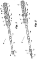
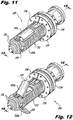
- FIG. 1 a perspective view of an assembled instrument 100 for inserting an implant in accordance with the subject technology is shown.
- the instrument 100 is particularly useful for inserting interspinous process implants and fusion cage spacers in accordance with those shown in U.S. PG Pub. No. 2010/0234889 (the '889 application).
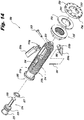
- Figure 2 a perspective view of the insertion instrument 100 mounted with an implant 200 in accordance with the '889 application is shown.
- the instrument 100 can be disassembled easily to allow for full and proper cleaning, then reassembled to be used again.
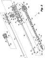
- the components of the instrument 100 are fabricated from medical grade stainless steel, alloys, and/or polymers (e.g., RULON, PEEK) or another like durable material to allow for repeated use, cleaning and reuse.
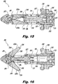
- the instrument 100 includes an elongated main body 102 having a proximal handle portion 104 that defines a central passage 106 and a distal portion 108 that selectively couples to the implant 200.
- the distal portion 108 forms axial slots 109 that allows compression of the tip 113.
- the tip 113 is roughly hexagonal shaped but as a result of the opposing slots 109, the tip 113 becomes two opposing, spaced apart "V" in cross-sectional shape.
- the tip 113 has four outer ridges 111, one ridge 111 on each flat section of the V-shape.
- the handle portion 104 also has stripes 127 to provide visual references to the user.
- the handle portion 131 has a distal guide portion 133.
- the handle portion 104 of the main body 102 also has a first pair of opposing locking tabs 115.
- the locking tabs 115 are hingedly connected to the main body 102 to rotate radially inward and outward by the surgeon or surgical assistant.
- the handle portion 104 also has a second pair of opposing locking tabs 117 that are located relatively proximally compared to the first locking tabs 115.
- the second locking tabs 117 are also hingedly connected to the main body 102 to rotate radially inward and outward by the user.
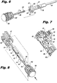
- the handle portion 104 defines an axial recess 134.
- the axial recess 134 is formed by an angled surface 135 (best seen in Figure 7 ).
- the main body 102 also forms an axial wing slot 103 with location indicia 105a-c adjacent the wing slot 103 as described in more detail with reference to Figure 23 among other figures herein.
- the indicia 105a-c combine with the reference notch 131 on the wings to indicate "unlocked,” “locked” and “deployed” positions of the instrument 100, respectively, as described in more detail below.
- the main body 102 and spike cap drive 104 includes alignment indicia 123,127 in the form of stripes 127 and an arrow 123, respectively.
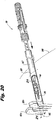
- a plunger 110 slides in the central passage 106.
- the plunger 110 has a distal pushing end 112 and a proximal locking end 114.
- the proximal locking end 114 has a relatively thicker radius that includes a series of spaced apart radial holes 118.
- Opposing radial wings 120 are formed adjacent a proximal recess 122.
- the radial wings 120 include a reference notch 131.
- the plunger 110 is shown coupled to a plunger knob 126.
- a plunger knob 126 has an externally threaded proximal end 128 that threadably couples to the axial threaded post 124 of the plunger 110.
- the plunger knob 126 has a proximal handle portion 130 for gripping to move the plunger 110 in the central passage 106.
- the plunger knob 126 has an annular recess 142 that extends completely around the plunger knob 126.
- the implant 200 comes in a variety of sizes so that an appropriate size can be selected for a desired amount of interspinous distraction. Any technique now known and later developed may be used to determine the proper interspinous distraction. Once the proper size implant 200 is selected, the corresponding or matching adapter 170 can be selected. Once the adapter 170 has been chosen, the implant 200 can be mounted on the insertion instrument 100.
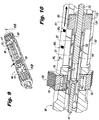
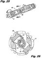
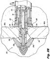
- Figure 28 is a dorsal view illustrating the implant 200 with the spike cap 230 urged distally by the nut 235, engaging the adjacent spinous processes 381a, 381b.
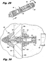
- Figure 30 is a dorsal view illustrating the implant 200 fixed in place with removal of the insertion instrument 100.
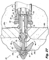
- the spike cap drive 140 is rotated clockwise relative to the main body 102 by the handle portion 148. Turning the handle portion 148 turns the adapter 170 and thereby the hex nut 235. Once the spike cap 230 engages the spinous processes 381a, 381b, the blades 220a, 220b are drawn proximally into engagement with the bone 381a, 381b. A flat portion of the implant 200 is not threaded so that the implant 200 slides proximally. While the spike cap drive 140 is used to tighten the hex nut 235, the surgeon can feel the spike cap 230 become fully seated or full seating is seen in an accompanying fluoroscopy display. Preferably, one or more osteogenesis promoting substances can be packed in and/or around the implant 200 to promote bone ingrowth and/or spinal fusion, if desired.
Landscapes
- Health & Medical Sciences (AREA)
- Orthopedic Medicine & Surgery (AREA)
- Life Sciences & Earth Sciences (AREA)
- Surgery (AREA)
- Neurology (AREA)
- Heart & Thoracic Surgery (AREA)
- Engineering & Computer Science (AREA)
- Biomedical Technology (AREA)
- Nuclear Medicine, Radiotherapy & Molecular Imaging (AREA)
- Medical Informatics (AREA)
- Molecular Biology (AREA)
- Animal Behavior & Ethology (AREA)
- General Health & Medical Sciences (AREA)
- Public Health (AREA)
- Veterinary Medicine (AREA)
- Prostheses (AREA)
- Surgical Instruments (AREA)
Claims (5)
- Einsetzmittel (100) für ein Wirbelsäulenimplantat (200), wobei das Wirbelsäulenimplantat umfasst:a) einen länglichen Körper (212), um als Abstandshalter zu fungieren, der in einem interspinalen Soll-Fortsatzraum zwischen zwei benachbarten spinalen Fortsätzen angeordnet ist, wobei der Körper (212) ein Inneres und eine proximale innere Aussparung für einen Zugang zum Inneren bildet, wobei die proximale innere Aussparung eine transversale Nut (253) bildet;b) einen distalen Anker, der zumindest teilweise mit Gewinde versehen ist und gegenüberliegende radiale einsetzbare Schaufeln (220) aufweist, die zur Drehung um einen Stift herum befestigt sind, der transversal im Inneren befestigt ist;c) einen proximalen Anker mit einer Dornkappe (230), die befestigt ist, um entlang des Körpers (212) zu gleiten und mit einer Antriebsmutter (235), die zur Längsbewegung entlang des Körpers (212) zwischen einer ersten Position, die vom distalen Anker beabstandet ist, und einer zweiten Position, die relativ näher zum distalen Anker ist, befestigt ist, um dadurch die beiden benachbarten spinalen Fortsätze zwischen der Dornkappe (230) und dem distalen Anker zusammenzudrücken; undd) einen Betätigungsstößel (226), der gleitbeweglich innerhalb des Inneren zum Bewegen der Schaufeln (220) von einer verstauten Position zu einer implantateingesetzten Position ist, wobei das Einsetzmittel (100) aufweist:- einen länglichen Hauptkörper (102) mit einem distalen Verriegelungsbereich (108) zum Verbinden mit dem Implantat (200) und einem proximalen Griffbereich (104), wobei der Hauptkörper einen mittleren Durchgang (106) bildet und der distale Verriegelungsbereich (108) Außenkanten (111) und zumindest einen Schlitz (109) aufweist, um zumindest einer der Außenkanten (111) ein Durchbiegen radial nach Innen zu ermöglichen;- einen Stößel (110), der gleitbeweglich im mittleren Durchgang (106) zur Bewegung zwischen einer nicht verriegelten Position zum Befestigen des Implantats (200) auf dem distalen Verriegelungsbereich (108), einer verriegelten Position zum Verriegeln des Implantats (200) auf dem distalen Verriegelungsbereich (108) und einer eingesetzten Einsetzmittel-Position zum Einsetzen des Betätigungsstößels verbunden ist, um die Schaufeln von der verstauten Position zur eingesetzten Position zu bewegen;- einen Dornkappenantrieb (140), der drehbeweglich am Hauptkörper (102) befestigt ist, mit einem Sockelende (156) zum Eingriff mit der Antriebsmutter (235), um die Dornkappe (230) abwechselnd zu bewegen; und- einen Stößelanschlag (132), der mit dem Hauptkörper verbunden ist, wobei der Stößelanschlag einen mittleren Durchgang (136) aufweist, der im Wesentlichen mit dem mittleren Durchgang (106) des Hauptkörpers ausgerichtet ist, wobei:- der Stößelanschlag (132) einen Vorsprung (139) aufweist, der in den mittleren Durchgang hineinragt; und- der Stößel (110) eine dreiteilige Nut (116) bildet, die den Vorsprung (139) erfasst, wenn der Stößel (110) gleitet und sich innerhalb des mittleren Durchgangs (106) dreht, wobei die dreiteilige Nut (116) ein erstes axiales Teil, das die nicht verriegelte Position bildet, ein radiales Zwischenteil, das die verriegelte Position bildet und ein zweites axiales Teil, das die eingesetzte Einsetzmittel-Position bildet, aufweist.
- Einsetzmittel gemäß Anspruch 1, wobei:- in der unverriegelten Position, wenn das Implantat (200) am Einsetzmittel befestigt ist, die Außenkanten (111) in der unverriegelten Position mit der transversalen Nut (253) in Eingriff sind;- in der verriegelten Position die Außenkanten mit der transversalen Nut (253) in Eingriff sind und sich der Stößel (110) durch den mittleren Durchgang (106) erstreckt, um mit den Außenkanten konzentrisch zu sein; und- in der eingesetzten Einsetzmittel-Position sich der Stößel aus dem mittleren Durchgang (106) heraus erstreckt, um den Betätigungsstößel (226) des Implantats (200) zu bewegen.
- Einsetzmittel gemäß einem der vorhergehenden Ansprüche, das ferner einen Adapter (170), der mit dem Implantat (200) übereinstimmt, zum Verbinden des Sockelendes (156) mit der Antriebsmutter (235) des Implantats (200) aufweist.
- Einsetzmittel gemäß einem der vorhergehenden Ansprüche, wobei die Dornkappe (230) mit dem Implantatkörper (212) verkeilt ist, um eine Drehung beim Antrieb zu verhindern, und das Implantat (200) flache Bereiche (217) aufweist, um eine effiziente Kompression des Implantats (200) beim Eingriff in die spinalen Fortsätze zu ermöglichen.
- Einsetzmittel gemäß einem der vorhergehenden Ansprüche, das ferner Polytetrafluorethylen (PTFE) auf zumindest entweder dem Dornkappenantrieb (140) oder dem Hauptkörper (102) aufweist, um einen Verschleiß zu reduzieren und eine gleichmäßige Betätigung vorzusehen, wenn die Dornkappe gedreht wird.
Applications Claiming Priority (2)
| Application Number | Priority Date | Filing Date | Title |
|---|---|---|---|
| US201361828384P | 2013-05-29 | 2013-05-29 | |
| PCT/US2014/039951 WO2014194046A1 (en) | 2013-05-29 | 2014-05-29 | Instrument for inserting an interspinous process implant |
Publications (3)
| Publication Number | Publication Date |
|---|---|
| EP3003185A1 EP3003185A1 (de) | 2016-04-13 |
| EP3003185A4 EP3003185A4 (de) | 2017-01-18 |
| EP3003185B1 true EP3003185B1 (de) | 2018-05-23 |
Family
ID=51985962
Family Applications (1)
| Application Number | Title | Priority Date | Filing Date |
|---|---|---|---|
| EP14804610.5A Active EP3003185B1 (de) | 2013-05-29 | 2014-05-29 | Instrument zum einsetzen eines dornfortsatzimplantats |
Country Status (11)
| Country | Link |
|---|---|
| US (3) | US9603648B2 (de) |
| EP (1) | EP3003185B1 (de) |
| JP (1) | JP6500013B2 (de) |
| KR (1) | KR20160016919A (de) |
| CN (1) | CN105530881B (de) |
| AU (1) | AU2014274197A1 (de) |
| BR (1) | BR112015029573A2 (de) |
| CA (1) | CA2913463A1 (de) |
| ES (1) | ES2692277T3 (de) |
| MX (1) | MX2015016394A (de) |
| WO (1) | WO2014194046A1 (de) |
Cited By (1)
| Publication number | Priority date | Publication date | Assignee | Title |
|---|---|---|---|---|
| US12133664B2 (en) | 2022-12-13 | 2024-11-05 | Spinal Simplicity, Llc | Medical implant |
Families Citing this family (28)
| Publication number | Priority date | Publication date | Assignee | Title |
|---|---|---|---|---|
| US8808335B2 (en) * | 2010-03-08 | 2014-08-19 | Miami Device Solutions, Llc | Locking element for a polyaxial bone anchor, bone plate assembly and tool |
| US9526553B2 (en) * | 2014-04-04 | 2016-12-27 | K2M, Inc. | Screw insertion instrument |
| USD764054S1 (en) * | 2014-05-29 | 2016-08-16 | Spinal Simplicity Llc. | Insertion instrument |
| US10603094B2 (en) | 2015-03-31 | 2020-03-31 | Depuy Ireland Unlimited Company | System and method for attaching a surgical instrument to a patient's bone |
| US11090147B2 (en) | 2015-10-08 | 2021-08-17 | Cardiovascular Systems, Inc. | System for unlocking a device from a guide wire |
| US20220226027A1 (en) * | 2016-04-14 | 2022-07-21 | Spinal Simplicity, Llc | Interspinous implant insertion instrument with wing actuation tool |
| US11510710B2 (en) * | 2016-04-14 | 2022-11-29 | Spinal Simplicity, Llc | Locking system for interspinous implant insertion instrument |
| US10420591B2 (en) * | 2016-04-14 | 2019-09-24 | Spinal Simplicity, Llc | Interspinous implant insertion instrument with staggered path implant deployment mechanism |
| CN106420121B (zh) * | 2016-08-31 | 2018-09-14 | 广州爱锘德医疗器械有限公司 | 弧形融合器的操作机构 |
| US10779866B2 (en) | 2016-12-29 | 2020-09-22 | K2M, Inc. | Rod reducer assembly |
| KR101852973B1 (ko) * | 2017-01-31 | 2018-05-02 | 주식회사 솔고 바이오메디칼 | 척추간 삽입용 케이지 삽입 장치 |
| CN109247959B (zh) * | 2017-07-13 | 2020-07-03 | 先健科技(深圳)有限公司 | 封堵器推送装置及输送系统 |
| US9987967B1 (en) * | 2017-08-17 | 2018-06-05 | Trident Systems Llc | Deck fitting with removable fixture |
| US10856924B2 (en) * | 2017-12-21 | 2020-12-08 | Globus Medical Inc. | Headless compression screw driver system |
| IT201800003973A1 (it) * | 2018-03-23 | 2019-09-23 | Techlamed S R L | Dispositivo per la fusione interspinosa |
| JP2021525119A (ja) * | 2018-05-23 | 2021-09-24 | スミス アンド ネフュー インコーポレイテッド | アンカ送達システム |
| US10722703B2 (en) | 2018-08-23 | 2020-07-28 | Advanced Neuromodulation Systems, Inc. | Systems and methods for deploying a paddle neurostimulation lead configured to provide DRG stimulation therapy |
| US20220054168A1 (en) * | 2020-08-19 | 2022-02-24 | Conmed Corporation | Driver for arthroscopic implant |
| US11490934B1 (en) * | 2021-11-16 | 2022-11-08 | Warsaw Orthopedic, Inc. | Spinal implant system and method |
| KR102689316B1 (ko) * | 2022-01-26 | 2024-07-30 | 주식회사 에어스 | 푸쉬타입 한쪽 피질골 고정 앵커 |
| EP4496523A1 (de) * | 2022-03-23 | 2025-01-29 | Naven Duggal | Kompressionssysteme und verfahren für frakturen und fusionen |
| WO2023196535A1 (en) | 2022-04-08 | 2023-10-12 | Spinal Simplicity, Llc | Interspinous implant insertion instrument with wing actuation tool |
| US11766280B1 (en) * | 2022-04-08 | 2023-09-26 | Spinal Simplicity, Llc | Interspinous implant insertion instrument with wing actuation tool |
| US11504828B1 (en) * | 2022-06-30 | 2022-11-22 | The Seaberg Company, Inc. | Adapter for intraosseous needle assembly |
| US12295850B2 (en) | 2022-12-13 | 2025-05-13 | Spinal Simplicity, Llc | Systems, methods, and devices for lateral and posterior sacroiliac joint fusion |
| WO2024173421A2 (en) | 2023-02-13 | 2024-08-22 | FloSpine, LLC | Interspinous-interlaminar stabilization systems and methods |
| US12390340B2 (en) * | 2023-03-15 | 2025-08-19 | Boston Scientific Neuromodulation Corporation | Interspinous spacer with a range of deployment positions and methods and systems |
| US12605169B1 (en) | 2025-06-06 | 2026-04-21 | University Of Utah Research Foundation | Osteochondral transfer systems and methods |
Family Cites Families (25)
| Publication number | Priority date | Publication date | Assignee | Title |
|---|---|---|---|---|
| US6716216B1 (en) * | 1998-08-14 | 2004-04-06 | Kyphon Inc. | Systems and methods for treating vertebral bodies |
| US7887539B2 (en) * | 2003-01-24 | 2011-02-15 | Depuy Spine, Inc. | Spinal rod approximators |
| US7226453B2 (en) * | 2004-03-31 | 2007-06-05 | Depuy Spine, Inc. | Instrument for inserting, adjusting and removing pedicle screws and other orthopedic implants |
| US8706259B2 (en) * | 2004-04-30 | 2014-04-22 | Boston Scientific Neuromodulation Corporation | Insertion tool for paddle-style electrode |
| US8128662B2 (en) * | 2004-10-20 | 2012-03-06 | Vertiflex, Inc. | Minimally invasive tooling for delivery of interspinous spacer |
| US20080154277A1 (en) * | 2004-10-26 | 2008-06-26 | Scott Machalk | Tool apparatus for locking a spinal rod in an anchoring device therefor |
| US20070270876A1 (en) * | 2006-04-07 | 2007-11-22 | Yi-Chen Kuo | Vertebra bone cement introduction system |
| BRPI0716665A2 (pt) * | 2006-08-17 | 2013-12-10 | Synthes Gmbh | Acionador para inserir um parafuso para osso |
| US8641764B2 (en) | 2006-10-11 | 2014-02-04 | G&L Consulting, Llc | Spine implant insertion device and method |
| US9545267B2 (en) * | 2007-03-26 | 2017-01-17 | Globus Medical, Inc. | Lateral spinous process spacer |
| US8142479B2 (en) * | 2007-05-01 | 2012-03-27 | Spinal Simplicity Llc | Interspinous process implants having deployable engagement arms |
| US8540718B2 (en) * | 2007-10-23 | 2013-09-24 | Aesculap Implant Systems, Llc | Rod persuader |
| US20090326545A1 (en) * | 2008-06-26 | 2009-12-31 | Amedica Corporation | Systems and methods for inserting a bone anchor without a pilot hole |
| US8172878B2 (en) * | 2008-08-27 | 2012-05-08 | Yue James J | Conical interspinous apparatus and a method of performing interspinous distraction |
| CA2734995A1 (en) * | 2008-08-28 | 2010-03-04 | Synthes Usa, Llc | Bone-derived interspinous spacer |
| CA2751750C (en) * | 2009-02-11 | 2017-02-07 | Spinal Simplicity Llc | Interspinous process implants having deployable engagement arms |
| US8945184B2 (en) * | 2009-03-13 | 2015-02-03 | Spinal Simplicity Llc. | Interspinous process implant and fusion cage spacer |
| US9801732B2 (en) * | 2009-10-30 | 2017-10-31 | Spinefrontier, Inc | System and method for an intervertebral implant assembly |
| US8475467B2 (en) * | 2009-12-07 | 2013-07-02 | Globus Medical, Inc. | Derotation apparatus for treating spinal irregularities |
| US9480576B2 (en) * | 2010-08-27 | 2016-11-01 | Thompson Mis | Methods and systems for interbody implant and bone graft delivery |
| US8777960B2 (en) * | 2011-03-28 | 2014-07-15 | DePuy Synthes Products, LLC | Interlock driving instrument |
| US9572605B2 (en) * | 2012-10-09 | 2017-02-21 | Warsaw Orthopedic, Inc. | Surgical instrument and method |
| US9526533B1 (en) * | 2014-09-12 | 2016-12-27 | Roberto J. Aranibar | Spinal repair implants and related methods |
| US11278325B2 (en) * | 2015-03-11 | 2022-03-22 | Warsaw Orthopedic, Inc. | Surgical instrument and method |
| US11344354B2 (en) * | 2019-09-09 | 2022-05-31 | Warsaw Orthopedic, Inc. | Surgical instrument and method |
-
2014
- 2014-05-29 MX MX2015016394A patent/MX2015016394A/es unknown
- 2014-05-29 JP JP2016516808A patent/JP6500013B2/ja active Active
- 2014-05-29 AU AU2014274197A patent/AU2014274197A1/en not_active Abandoned
- 2014-05-29 CA CA2913463A patent/CA2913463A1/en not_active Abandoned
- 2014-05-29 WO PCT/US2014/039951 patent/WO2014194046A1/en not_active Ceased
- 2014-05-29 KR KR1020157036866A patent/KR20160016919A/ko not_active Withdrawn
- 2014-05-29 BR BR112015029573A patent/BR112015029573A2/pt not_active IP Right Cessation
- 2014-05-29 ES ES14804610.5T patent/ES2692277T3/es active Active
- 2014-05-29 US US14/290,183 patent/US9603648B2/en active Active
- 2014-05-29 CN CN201480042702.4A patent/CN105530881B/zh active Active
- 2014-05-29 EP EP14804610.5A patent/EP3003185B1/de active Active
-
2017
- 2017-03-23 US US15/467,533 patent/US10285739B2/en active Active
-
2019
- 2019-04-05 US US16/376,774 patent/US11234740B2/en active Active
Non-Patent Citations (1)
| Title |
|---|
| None * |
Cited By (1)
| Publication number | Priority date | Publication date | Assignee | Title |
|---|---|---|---|---|
| US12133664B2 (en) | 2022-12-13 | 2024-11-05 | Spinal Simplicity, Llc | Medical implant |
Also Published As
| Publication number | Publication date |
|---|---|
| CN105530881B (zh) | 2019-04-26 |
| JP6500013B2 (ja) | 2019-04-10 |
| BR112015029573A2 (pt) | 2017-07-25 |
| EP3003185A4 (de) | 2017-01-18 |
| US11234740B2 (en) | 2022-02-01 |
| KR20160016919A (ko) | 2016-02-15 |
| JP2016523120A (ja) | 2016-08-08 |
| US20170189079A1 (en) | 2017-07-06 |
| US10285739B2 (en) | 2019-05-14 |
| CN105530881A (zh) | 2016-04-27 |
| MX2015016394A (es) | 2016-04-11 |
| US20140358186A1 (en) | 2014-12-04 |
| ES2692277T3 (es) | 2018-12-03 |
| EP3003185A1 (de) | 2016-04-13 |
| US9603648B2 (en) | 2017-03-28 |
| US20190231398A1 (en) | 2019-08-01 |
| CA2913463A1 (en) | 2014-12-04 |
| AU2014274197A1 (en) | 2015-12-10 |
| WO2014194046A1 (en) | 2014-12-04 |
Similar Documents
| Publication | Publication Date | Title |
|---|---|---|
| US11234740B2 (en) | Instrument for inserting an interspinous process implant | |
| US11298161B2 (en) | Interspinous implant insertion instrument with staggered path implant deployment mechanism | |
| US11801075B2 (en) | Instrument for inserting an interspinous process implant | |
| US12369899B2 (en) | Devices and systems for surgical retraction | |
| US9907581B2 (en) | Interspinous process implant and fusion cage spacer | |
| US12588935B2 (en) | Interspinous implant insertion instrument with staggered path implant deployment mechanism | |
| US11510710B2 (en) | Locking system for interspinous implant insertion instrument | |
| US20230329761A1 (en) | Interspinous implant insertion instrument with wing actuation tool | |
| US20250345054A1 (en) | Devices and systems for surgical retraction | |
| HK1170140B (en) | Interspinous process implant and fusion cage spacer |
Legal Events
| Date | Code | Title | Description |
|---|---|---|---|
| PUAI | Public reference made under article 153(3) epc to a published international application that has entered the european phase |
Free format text: ORIGINAL CODE: 0009012 |
|
| 17P | Request for examination filed |
Effective date: 20151202 |
|
| AK | Designated contracting states |
Kind code of ref document: A1 Designated state(s): AL AT BE BG CH CY CZ DE DK EE ES FI FR GB GR HR HU IE IS IT LI LT LU LV MC MK MT NL NO PL PT RO RS SE SI SK SM TR |
|
| AX | Request for extension of the european patent |
Extension state: BA ME |
|
| DAX | Request for extension of the european patent (deleted) | ||
| A4 | Supplementary search report drawn up and despatched |
Effective date: 20161220 |
|
| RIC1 | Information provided on ipc code assigned before grant |
Ipc: A61B 17/70 20060101ALI20161214BHEP Ipc: A61F 2/44 20060101ALI20161214BHEP Ipc: A61B 17/88 20060101AFI20161214BHEP |
|
| GRAP | Despatch of communication of intention to grant a patent |
Free format text: ORIGINAL CODE: EPIDOSNIGR1 |
|
| INTG | Intention to grant announced |
Effective date: 20171130 |
|
| GRAS | Grant fee paid |
Free format text: ORIGINAL CODE: EPIDOSNIGR3 |
|
| GRAA | (expected) grant |
Free format text: ORIGINAL CODE: 0009210 |
|
| AK | Designated contracting states |
Kind code of ref document: B1 Designated state(s): AL AT BE BG CH CY CZ DE DK EE ES FI FR GB GR HR HU IE IS IT LI LT LU LV MC MK MT NL NO PL PT RO RS SE SI SK SM TR |
|
| REG | Reference to a national code |
Ref country code: GB Ref legal event code: FG4D |
|
| REG | Reference to a national code |
Ref country code: CH Ref legal event code: EP |
|
| REG | Reference to a national code |
Ref country code: IE Ref legal event code: FG4D |
|
| REG | Reference to a national code |
Ref country code: AT Ref legal event code: REF Ref document number: 1000875 Country of ref document: AT Kind code of ref document: T Effective date: 20180615 |
|
| REG | Reference to a national code |
Ref country code: DE Ref legal event code: R096 Ref document number: 602014025932 Country of ref document: DE |
|
| REG | Reference to a national code |
Ref country code: FR Ref legal event code: PLFP Year of fee payment: 5 |
|
| REG | Reference to a national code |
Ref country code: NL Ref legal event code: MP Effective date: 20180523 |
|
| REG | Reference to a national code |
Ref country code: LT Ref legal event code: MG4D |
|
| PG25 | Lapsed in a contracting state [announced via postgrant information from national office to epo] |
Ref country code: SE Free format text: LAPSE BECAUSE OF FAILURE TO SUBMIT A TRANSLATION OF THE DESCRIPTION OR TO PAY THE FEE WITHIN THE PRESCRIBED TIME-LIMIT Effective date: 20180523 Ref country code: FI Free format text: LAPSE BECAUSE OF FAILURE TO SUBMIT A TRANSLATION OF THE DESCRIPTION OR TO PAY THE FEE WITHIN THE PRESCRIBED TIME-LIMIT Effective date: 20180523 Ref country code: NO Free format text: LAPSE BECAUSE OF FAILURE TO SUBMIT A TRANSLATION OF THE DESCRIPTION OR TO PAY THE FEE WITHIN THE PRESCRIBED TIME-LIMIT Effective date: 20180823 Ref country code: BG Free format text: LAPSE BECAUSE OF FAILURE TO SUBMIT A TRANSLATION OF THE DESCRIPTION OR TO PAY THE FEE WITHIN THE PRESCRIBED TIME-LIMIT Effective date: 20180823 Ref country code: LT Free format text: LAPSE BECAUSE OF FAILURE TO SUBMIT A TRANSLATION OF THE DESCRIPTION OR TO PAY THE FEE WITHIN THE PRESCRIBED TIME-LIMIT Effective date: 20180523 |
|
| PGFP | Annual fee paid to national office [announced via postgrant information from national office to epo] |
Ref country code: FR Payment date: 20180827 Year of fee payment: 5 Ref country code: ES Payment date: 20180904 Year of fee payment: 5 |
|
| PG25 | Lapsed in a contracting state [announced via postgrant information from national office to epo] |
Ref country code: GR Free format text: LAPSE BECAUSE OF FAILURE TO SUBMIT A TRANSLATION OF THE DESCRIPTION OR TO PAY THE FEE WITHIN THE PRESCRIBED TIME-LIMIT Effective date: 20180824 Ref country code: NL Free format text: LAPSE BECAUSE OF FAILURE TO SUBMIT A TRANSLATION OF THE DESCRIPTION OR TO PAY THE FEE WITHIN THE PRESCRIBED TIME-LIMIT Effective date: 20180523 Ref country code: LV Free format text: LAPSE BECAUSE OF FAILURE TO SUBMIT A TRANSLATION OF THE DESCRIPTION OR TO PAY THE FEE WITHIN THE PRESCRIBED TIME-LIMIT Effective date: 20180523 Ref country code: HR Free format text: LAPSE BECAUSE OF FAILURE TO SUBMIT A TRANSLATION OF THE DESCRIPTION OR TO PAY THE FEE WITHIN THE PRESCRIBED TIME-LIMIT Effective date: 20180523 Ref country code: RS Free format text: LAPSE BECAUSE OF FAILURE TO SUBMIT A TRANSLATION OF THE DESCRIPTION OR TO PAY THE FEE WITHIN THE PRESCRIBED TIME-LIMIT Effective date: 20180523 |
|
| REG | Reference to a national code |
Ref country code: ES Ref legal event code: FG2A Ref document number: 2692277 Country of ref document: ES Kind code of ref document: T3 Effective date: 20181203 |
|
| REG | Reference to a national code |
Ref country code: CH Ref legal event code: PL |
|
| REG | Reference to a national code |
Ref country code: AT Ref legal event code: MK05 Ref document number: 1000875 Country of ref document: AT Kind code of ref document: T Effective date: 20180523 |
|
| REG | Reference to a national code |
Ref country code: BE Ref legal event code: MM Effective date: 20180531 |
|
| PG25 | Lapsed in a contracting state [announced via postgrant information from national office to epo] |
Ref country code: RO Free format text: LAPSE BECAUSE OF FAILURE TO SUBMIT A TRANSLATION OF THE DESCRIPTION OR TO PAY THE FEE WITHIN THE PRESCRIBED TIME-LIMIT Effective date: 20180523 Ref country code: CZ Free format text: LAPSE BECAUSE OF FAILURE TO SUBMIT A TRANSLATION OF THE DESCRIPTION OR TO PAY THE FEE WITHIN THE PRESCRIBED TIME-LIMIT Effective date: 20180523 Ref country code: AT Free format text: LAPSE BECAUSE OF FAILURE TO SUBMIT A TRANSLATION OF THE DESCRIPTION OR TO PAY THE FEE WITHIN THE PRESCRIBED TIME-LIMIT Effective date: 20180523 Ref country code: EE Free format text: LAPSE BECAUSE OF FAILURE TO SUBMIT A TRANSLATION OF THE DESCRIPTION OR TO PAY THE FEE WITHIN THE PRESCRIBED TIME-LIMIT Effective date: 20180523 Ref country code: PL Free format text: LAPSE BECAUSE OF FAILURE TO SUBMIT A TRANSLATION OF THE DESCRIPTION OR TO PAY THE FEE WITHIN THE PRESCRIBED TIME-LIMIT Effective date: 20180523 Ref country code: DK Free format text: LAPSE BECAUSE OF FAILURE TO SUBMIT A TRANSLATION OF THE DESCRIPTION OR TO PAY THE FEE WITHIN THE PRESCRIBED TIME-LIMIT Effective date: 20180523 Ref country code: SK Free format text: LAPSE BECAUSE OF FAILURE TO SUBMIT A TRANSLATION OF THE DESCRIPTION OR TO PAY THE FEE WITHIN THE PRESCRIBED TIME-LIMIT Effective date: 20180523 |
|
| REG | Reference to a national code |
Ref country code: IE Ref legal event code: MM4A |
|
| REG | Reference to a national code |
Ref country code: DE Ref legal event code: R097 Ref document number: 602014025932 Country of ref document: DE |
|
| PG25 | Lapsed in a contracting state [announced via postgrant information from national office to epo] |
Ref country code: LI Free format text: LAPSE BECAUSE OF NON-PAYMENT OF DUE FEES Effective date: 20180531 Ref country code: CH Free format text: LAPSE BECAUSE OF NON-PAYMENT OF DUE FEES Effective date: 20180531 Ref country code: SM Free format text: LAPSE BECAUSE OF FAILURE TO SUBMIT A TRANSLATION OF THE DESCRIPTION OR TO PAY THE FEE WITHIN THE PRESCRIBED TIME-LIMIT Effective date: 20180523 |
|
| PG25 | Lapsed in a contracting state [announced via postgrant information from national office to epo] |
Ref country code: MC Free format text: LAPSE BECAUSE OF FAILURE TO SUBMIT A TRANSLATION OF THE DESCRIPTION OR TO PAY THE FEE WITHIN THE PRESCRIBED TIME-LIMIT Effective date: 20180523 Ref country code: LU Free format text: LAPSE BECAUSE OF NON-PAYMENT OF DUE FEES Effective date: 20180529 |
|
| PLBE | No opposition filed within time limit |
Free format text: ORIGINAL CODE: 0009261 |
|
| STAA | Information on the status of an ep patent application or granted ep patent |
Free format text: STATUS: NO OPPOSITION FILED WITHIN TIME LIMIT |
|
| PG25 | Lapsed in a contracting state [announced via postgrant information from national office to epo] |
Ref country code: IE Free format text: LAPSE BECAUSE OF NON-PAYMENT OF DUE FEES Effective date: 20180529 |
|
| 26N | No opposition filed |
Effective date: 20190226 |
|
| PG25 | Lapsed in a contracting state [announced via postgrant information from national office to epo] |
Ref country code: BE Free format text: LAPSE BECAUSE OF NON-PAYMENT OF DUE FEES Effective date: 20180531 Ref country code: SI Free format text: LAPSE BECAUSE OF FAILURE TO SUBMIT A TRANSLATION OF THE DESCRIPTION OR TO PAY THE FEE WITHIN THE PRESCRIBED TIME-LIMIT Effective date: 20180523 |
|
| PG25 | Lapsed in a contracting state [announced via postgrant information from national office to epo] |
Ref country code: AL Free format text: LAPSE BECAUSE OF FAILURE TO SUBMIT A TRANSLATION OF THE DESCRIPTION OR TO PAY THE FEE WITHIN THE PRESCRIBED TIME-LIMIT Effective date: 20180523 |
|
| PG25 | Lapsed in a contracting state [announced via postgrant information from national office to epo] |
Ref country code: MT Free format text: LAPSE BECAUSE OF NON-PAYMENT OF DUE FEES Effective date: 20180529 |
|
| PG25 | Lapsed in a contracting state [announced via postgrant information from national office to epo] |
Ref country code: TR Free format text: LAPSE BECAUSE OF FAILURE TO SUBMIT A TRANSLATION OF THE DESCRIPTION OR TO PAY THE FEE WITHIN THE PRESCRIBED TIME-LIMIT Effective date: 20180523 |
|
| PG25 | Lapsed in a contracting state [announced via postgrant information from national office to epo] |
Ref country code: PT Free format text: LAPSE BECAUSE OF FAILURE TO SUBMIT A TRANSLATION OF THE DESCRIPTION OR TO PAY THE FEE WITHIN THE PRESCRIBED TIME-LIMIT Effective date: 20180523 |
|
| PG25 | Lapsed in a contracting state [announced via postgrant information from national office to epo] |
Ref country code: MK Free format text: LAPSE BECAUSE OF NON-PAYMENT OF DUE FEES Effective date: 20180523 Ref country code: CY Free format text: LAPSE BECAUSE OF FAILURE TO SUBMIT A TRANSLATION OF THE DESCRIPTION OR TO PAY THE FEE WITHIN THE PRESCRIBED TIME-LIMIT Effective date: 20180523 Ref country code: HU Free format text: LAPSE BECAUSE OF FAILURE TO SUBMIT A TRANSLATION OF THE DESCRIPTION OR TO PAY THE FEE WITHIN THE PRESCRIBED TIME-LIMIT; INVALID AB INITIO Effective date: 20140529 Ref country code: FR Free format text: LAPSE BECAUSE OF NON-PAYMENT OF DUE FEES Effective date: 20190531 |
|
| PG25 | Lapsed in a contracting state [announced via postgrant information from national office to epo] |
Ref country code: IS Free format text: LAPSE BECAUSE OF FAILURE TO SUBMIT A TRANSLATION OF THE DESCRIPTION OR TO PAY THE FEE WITHIN THE PRESCRIBED TIME-LIMIT Effective date: 20180923 |
|
| REG | Reference to a national code |
Ref country code: ES Ref legal event code: FD2A Effective date: 20200930 |
|
| PG25 | Lapsed in a contracting state [announced via postgrant information from national office to epo] |
Ref country code: ES Free format text: LAPSE BECAUSE OF NON-PAYMENT OF DUE FEES Effective date: 20190530 |
|
| P01 | Opt-out of the competence of the unified patent court (upc) registered |
Effective date: 20230508 |
|
| PGFP | Annual fee paid to national office [announced via postgrant information from national office to epo] |
Ref country code: DE Payment date: 20250429 Year of fee payment: 12 |
|
| PGFP | Annual fee paid to national office [announced via postgrant information from national office to epo] |
Ref country code: GB Payment date: 20250501 Year of fee payment: 12 |
|
| PGFP | Annual fee paid to national office [announced via postgrant information from national office to epo] |
Ref country code: IT Payment date: 20250522 Year of fee payment: 12 |