EP3003106B1 - Friteuse à air - Google Patents
Friteuse à air Download PDFInfo
- Publication number
- EP3003106B1 EP3003106B1 EP14726980.7A EP14726980A EP3003106B1 EP 3003106 B1 EP3003106 B1 EP 3003106B1 EP 14726980 A EP14726980 A EP 14726980A EP 3003106 B1 EP3003106 B1 EP 3003106B1
- Authority
- EP
- European Patent Office
- Prior art keywords
- air
- food
- fan
- movement device
- preparation chamber
- Prior art date
- Legal status (The legal status is an assumption and is not a legal conclusion. Google has not performed a legal analysis and makes no representation as to the accuracy of the status listed.)
- Active
Links
Images


Classifications
-
- A—HUMAN NECESSITIES
- A47—FURNITURE; DOMESTIC ARTICLES OR APPLIANCES; COFFEE MILLS; SPICE MILLS; SUCTION CLEANERS IN GENERAL
- A47J—KITCHEN EQUIPMENT; COFFEE MILLS; SPICE MILLS; APPARATUS FOR MAKING BEVERAGES
- A47J37/00—Baking; Roasting; Grilling; Frying
- A47J37/06—Roasters; Grills; Sandwich grills
-
- A—HUMAN NECESSITIES
- A21—BAKING; EDIBLE DOUGHS
- A21B—BAKERS' OVENS; MACHINES OR EQUIPMENT FOR BAKING
- A21B1/00—Bakers' ovens
- A21B1/02—Bakers' ovens characterised by the heating arrangements
- A21B1/24—Ovens heated by media flowing therethrough
- A21B1/26—Ovens heated by media flowing therethrough by hot air
-
- A—HUMAN NECESSITIES
- A23—FOODS OR FOODSTUFFS; TREATMENT THEREOF, NOT COVERED BY OTHER CLASSES
- A23L—FOODS, FOODSTUFFS OR NON-ALCOHOLIC BEVERAGES, NOT OTHERWISE PROVIDED FOR; PREPARATION OR TREATMENT THEREOF
- A23L5/00—Preparation or treatment of foods or foodstuffs, in general; Food or foodstuffs obtained thereby; Materials therefor
- A23L5/10—General methods of cooking foods, e.g. by roasting or frying
- A23L5/17—General methods of cooking foods, e.g. by roasting or frying in a gaseous atmosphere with forced air or gas circulation, in vacuum or under pressure
-
- A—HUMAN NECESSITIES
- A47—FURNITURE; DOMESTIC ARTICLES OR APPLIANCES; COFFEE MILLS; SPICE MILLS; SUCTION CLEANERS IN GENERAL
- A47J—KITCHEN EQUIPMENT; COFFEE MILLS; SPICE MILLS; APPARATUS FOR MAKING BEVERAGES
- A47J37/00—Baking; Roasting; Grilling; Frying
- A47J37/06—Roasters; Grills; Sandwich grills
- A47J37/0623—Small-size cooking ovens, i.e. defining an at least partially closed cooking cavity
- A47J37/0629—Small-size cooking ovens, i.e. defining an at least partially closed cooking cavity with electric heating elements
- A47J37/0641—Small-size cooking ovens, i.e. defining an at least partially closed cooking cavity with electric heating elements with forced air circulation, e.g. air fryers
-
- A—HUMAN NECESSITIES
- A47—FURNITURE; DOMESTIC ARTICLES OR APPLIANCES; COFFEE MILLS; SPICE MILLS; SUCTION CLEANERS IN GENERAL
- A47J—KITCHEN EQUIPMENT; COFFEE MILLS; SPICE MILLS; APPARATUS FOR MAKING BEVERAGES
- A47J39/00—Heat-insulated warming chambers; Cupboards with heating arrangements for warming kitchen utensils
- A47J39/003—Heat-insulated warming chambers; Cupboards with heating arrangements for warming kitchen utensils with forced air circulation
-
- A—HUMAN NECESSITIES
- A23—FOODS OR FOODSTUFFS; TREATMENT THEREOF, NOT COVERED BY OTHER CLASSES
- A23V—INDEXING SCHEME RELATING TO FOODS, FOODSTUFFS OR NON-ALCOHOLIC BEVERAGES AND LACTIC OR PROPIONIC ACID BACTERIA USED IN FOODSTUFFS OR FOOD PREPARATION
- A23V2002/00—Food compositions, function of food ingredients or processes for food or foodstuffs
Definitions
- the present invention relates to food preparation and relates in particular to an apparatus for preparing food and a method for preparing food.
- An example for an apparatus for preparing food is the Philips air fryer, which is an appliance that can cook food, for example fries or chicken, with hot air. In order to heat the food for the preparation of the food, a flow of hot air is moved over the food to heat the same, respectively blown through the food containing volume for heating purposes. Such an appliance can be used, for example, in the household environment.
- an air flow rate through the entire food containing volume as high as possible is preferable. A high flow rate will ensure a relatively short cooking time and high food quality.
- WO 2012/032449 A1 describes an apparatus for preparing food with hot air. However, it has been shown that there is a need for shorter cooking times and higher food quality and thus a continuously growing demand for higher air flow rates.
- WO 2010/090369 A1 describes a heating cooker comprising a closed cooking chamber having a heating means for heating food contained in the closed cooking chamber, a ventilating chamber having an inlet passage and an outlet passage and connected to the cooking chamber through the inlet and outlet passages so that air circulates between the ventilating chamber and the cooking chamber, a rotating fan for circulating air between the cooking chamber and the ventilating chamber, a reservoir disposed adjacent to the ventilating chamber, and a spraying unit for radially spraying water in the reservoir to the ventilating chamber.
- an apparatus for preparing food comprising a food preparation chamber, an air movement device, a heating device, and air guiding means.
- the food preparation chamber is provided by a container structure at least partly enclosing a receiving volume for receiving food to be prepared, wherein the container structure comprises side walls, a bottom wall and an upper surface, wherein the bottom wall and/or one of the side walls is air-permeable providing an air entry opening for entering of hot air into the receiving volume.
- the container structure further comprises an air discharge opening at the upper surface.
- the heating device is configured to heat air of an air flow provided by the air movement device.
- the air guiding means provide an air duct arrangement from the discharge opening via the heating device and the air movement device to the air entry opening.
- the heating device is sidewards of, or above, the food preparation chamber and in that, during operation of the apparatus, the food is prepared by a through-streaming of hot air, i.e. through delivery of heat to the food by hot air, provided by the air movement device and the heating device.
- the air movement device is a fan with an air inlet and an air outlet.
- the fan is provided sidewards of the food preparation chamber.
- the air flow path is improved by arranging the fan closer to the air entry opening, where the most powerful air stream is needed for a proper and distributed entering of hot air into the food to be prepared.
- air guiding means providing an air duct arrangement relates to an air duct for allowing a circulating airflow.
- This can be provided by specific air channels or air conduits.
- this can, alternatively or in addition, also be provided by a housing of the apparatus enclosing the different devices and/or elements.
- the air guiding means comprise air duct segments in the vicinity of the air movement device, guiding the air from the air movement device to the food preparation chamber and from there back to the air movement device.
- a rather strong fan as an air movement device is provided inside the housing providing a circulating air flow, wherein the housing provides the air duct.
- the air movement device and the food preparation chamber are arranged such that a by-passing airflow of the food preparation chamber are prevented, e.g. the food preparation chamber is arranged close to an inner side-wall of the housing, the air movement device is also arranged close to an inner side-wall of the housing, and the air movement device and the food preparation chamber are arranged close to each other.
- through-streaming of hot air refers to the delivery of heat to the food to be prepared by the hot air.
- the air is not only reaching the upper surface of a food pile, but reaches also interior spaces of the food piles, for example in a pile of French fries, which are also referred to as chips in English, frites in French and Pommes Frites in German.
- the term "through-streaming of hot air” relates to hot air penetrating food, i.e. food piles, also referred to as food accumulation or food cluster.
- the hot air is not only moved around the outer boundary of the food, but directly actually heats up, i.e. transmits the heat directly to places inside the outer boundary areas, such as inside a staple of food parts.
- the air flow is provided with a high velocity and in particular with a high flow rate in the food preparation chamber.
- a high flow rate for example, an airflow rate of approximately minimum 20 1/sec is provided.
- an airflow path is provided with minimal number of changes in the cross-section.
- an airflow path is provided that changes its cross-section only in a range of approximately maximum 40% from the point where the air is exiting a ventilation device to the point where the air is entering the ventilation device again.
- changes of the cross-section are provided in a range of approximately 20% maximum. Nozzles should be avoided.
- a nozzle-free airflow path is arranged.
- the apparatus for preparing food delivers heat to the food to be prepared primarily by the hot air.
- a one-way heating is provided by the hot air, i.e. the hot air is the only heat source affecting, or impacting on the food in the food preparation chamber.
- the food preparation chamber provided by the container structure may comprise an insert like a basket structure, for example with a mesh structure to insert food in a facilitated way, and also to take the prepared food out of the apparatus again after preparation.
- the container structure may also be removable for filling and emptying purposes as well as for cleaning purposes.
- a fan as an air movement device, a fan is provided that has an air suction side and an air blowout side. In use, the air is blown out at the air blowout side with a mean blowing direction, and the mean blowing direction is provided with a tilted angle to both the horizontal and the vertical.
- This provides the advantage that the demand for guiding the air flow from the fan is reduced, since the air flow is already provided with a tilted angle, and not in a perpendicular manner, hitting, for example, lower surfaces.
- This is also advantageous in that the air flow at the air blowout side may show the maximum air speed with regards the to the circulating air flow path.
- the mean blowing direction can be seen as the primary or main blowing direction of the ventilated, i.e. moved air.
- the fan comprises at least one rotating part to move the air, such as a rotating blade, so that an axis of rotation is provided.
- the rotation of air movement elements, such as blades or the like, results in a respective blowing direction.
- the air movement device can be provided as an axial fan where a mean blowing direction is aligned with the axis of rotation, for example parallel to the rotation axis.
- the air movement device can be provided as a centrifugal fan, also referred to as a radial fan where a mean blowing direction is aligned with a tangential line with regard to the rotating blade(s), wherein the tangential line is perpendicular to the rotating axis.
- a centrifugal fan also referred to as a radial fan where a mean blowing direction is aligned with a tangential line with regard to the rotating blade(s), wherein the tangential line is perpendicular to the rotating axis.
- the direction of the rotating axis also determines the basic direction for the air stream, e.g. parallel in case of an axial fan, or perpendicular in case of a centrifugal fan.
- the axis of rotation is provided in a tilted angle with respect to the horizontal and/or the vertical.
- the fan is a centrifugal fan inside a fan housing with an axial air inlet and a radial air outlet.
- the centrifugal fan comprises a fan rotating in a rotating plane, and the rotating plane is provided with a tilted angle to both the horizontal and the vertical.
- the approximately perpendicular change of direction of the air flow inside the fan is integrated into the air flow path such that an air stream towards the fan from the food preparation chamber is provided with an angle larger than 90°, as well as the air exiting the fan shows a change of direction also with an angle larger than 90° before being applied to the food preparation chamber.
- the sharpest bent of the air flow path takes place in the fan itself. Since a sharp bent means an increased flow resistance for the air stream, the provision of angles larger than 90° in flow stream areas with higher flow speed means an advantage in terms of minimizing flow resistance for maximizing the flow.
- the provision of a rather sharp bent, or even the sharpest bent, inside the fan takes into consideration that the flow is influenced by the fan blades anyhow here.
- the tilted angle comprises an angle to the horizontal in a range of approximately 10° to 80°.
- an angle of approximately 45° is provided.
- the tilted arrangement also provides the advantage of a compact housing.
- a first line is defined by the rotating axis
- a second line is arranged perpendicular to the first line in the rotating plane
- a third line is perpendicular to the bottom wall, running through a centre of the bottom wall.
- the first line, the second line, and the third line are arranged in one plane and form a triangle.
- An inner circle of the triangle is arranged inside a housing structure of the apparatus.
- the first and the second line have an intersection point that is arranged in a middle region of the height of the housing structure.
- the inner circle has a maximum diameter.
- the apparatus is a desk-appliance apparatus.
- the term "desk-appliance" refers to an apparatus that is suitable for household purposes, which apparatus can be placed on different working surfaces in a kitchen of the table, or can be place in a shelf or on a cupboard.
- the desk-appliance relates to an appliance that can be manually moved and carried to different places by a single person. For household purposes the volume occupied by the appliance is constrained to sizes as small as possible.
- the desk-appliance relates to a portable appliance.
- the heating device is arranged out-of-sight of the receiving volume.
- a direct path for heat radiation is prevented.
- convection is the primarily source for the transfer of heat to the food to be prepared.
- a heater with increased power i.e. a heater with a higher heat transfer capability to the air flow
- the heater power is determined by the airflow (1/s)
- a higher air flow means that a higher power heater can be used without creating too much thermal differences between the lower and upper part of the food volume. Since the radiation from the top is prevented, i.e. blocked away, there is no need to achieve the delicate balance between radiation and convection any more.
- the temperature measuring device may switch off the heater if the air temperature reaches a too high, i.e.
- the heater only, or at least to a large extent, provides thermal energy in form of convection, i.e. in form of the hot air flow, and not by radiation.
- the heat source in form of the hot air results in good and homogenous food quality and also in short or at least minimized cooking times.
- an increasing range of food can be prepared.
- out-of-sight also comprises arrangements where the heater is placed out of sight to an extent of for example 70% or more. In an example, 90% are out-of sight.
- the heating device comprises one or more heating elements with a heat-providing surface. Some portions of the heat-providing surface are facing towards, i.e. in direction of the food preparation chamber.
- the following is meant by "out-of-sight": Seen from the food preparation chamber, a major part of the heat-providing surfaces facing the food preparation chamber is not visible, i.e. shielded. For example, if the heater would be replaced by light sources, only a little amount of the light providing surface would be seen from the food preparation chamber, or no light at all.
- the heat provided by the heating device is shielded or blocked from radiation towards the food.
- This provides an arrangement where heat, i.e. thermal energy is transferred to the food only (or at least to the largest extent) by the hot air.
- heat i.e. thermal energy is transferred to the food only (or at least to the largest extent) by the hot air.
- hot air may also heat up an enclosure or side-walls, and these surfaces will then transfer heat via radiation to the food. But this heat transmission is neglectable in relation to the heat transfer by the hot air.
- the heat transfer via hot air i.e. via convection is provided to be at least 70% of the thermal energy transfer to the food.
- at least 80, e.g. minimum 90 or 95% of the heat is provided by the hot air.
- the term "out-of-sight" relates to the direct path of heat radiation.
- the heat radiation path is independent from an optical path, i.e. non-related to a line of direct (visible) light.
- radiated heat may pass through a filter or air distributing element, while it is not possible to look through the filter, i.e. the filter is non-transparent.
- the heater is arranged such that the heat that is radiated by the heating elements, for example hot surfaces, which are provided for convection of heat by the air streaming passed the hot surfaces (the air streaming forced by the air movement means, such as a ventilation device or fan), also provide radiation.
- measures are provided that the radiated heat is not affecting the food in the food container.
- the measures may comprise the arrangement of the heating elements on the side of food container, i.e. next to the outer side of the side wall of the container.
- the measures may comprise shielding elements to prevent the heat transfer of the radiation.
- a container side wall may be arranged between the heating element and the part of the container volume arranged for receiving the food.
- separate protective elements are providing shielding for the heat radiation from the heating elements.
- the heating elements are arranged such that they radiate heat only in a direction away from the food.
- the heating device is arranged sidewards of the food preparation chamber.
- an air duct arrangement comprises a number of guiding portions, in which an air flow direction is changed.
- a first guiding portion is provided downstream, following the air movement device, and a second guiding portion is provided upstream in front of the air movement device.
- the first guiding portion provides a lower degree of change of direction of the air flow than the second guiding portion.
- a collecting device with a collecting volume is provided below the food preparation chamber for collecting residual material.
- oils and particles on a specific location in the removable pan of the appliance. Oils and particles that come from the food will be blown to this location by the hot air that exits the fan system. After the cooking process, the consumer can easily access this location for cleaning. This may lead to more frequent cleaning and prevents oils to be burned into the surfaces by repeated heating. Further, it is also preventing obstruction of the most important air flow path in the appliance. This supports the appliance performance to be consistent during the use. Another aspect is that the oil and particle volume may be located at a position where the air temperature is low enough to prevent smoking during the cooking process.
- an apparatus for preparing food comprising a food preparation chamber, an air movement device, a heating device, and air guiding means.
- the food preparation chamber is provided by a container structure at least partly enclosing a receiving volume for receiving food to be prepared by a through-streaming of hot air.
- the container structure comprises side walls and a bottom wall. The bottom wall and/or one of the side walls is air-permeable, providing an air entry opening for entering of hot air into the receiving volume.
- the container structure further comprises an air discharge opening.
- the heating device is configured to heat air of an air flow provided by the air movement device.
- the air guiding means provide an air duct arrangement from the discharge opening via the heating device and the air movement device to the air entry opening.
- a collecting device with a collection volume is provided below the food preparation structure for collecting residual material, e.g. oil and particles.
- an air guiding element is provided that directs a horizontal air flow below the container structure in an upwards direction towards the air entry opening.
- the collecting device is arranged besides the air guiding element on a side facing away from the horizontal air flow.
- an air distributing duct is provided below the air entry opening of the bottom wall.
- An air guide is provided as an elevation arranged on a lower surface of the air distributing duct below the air entry opening. The air guide is arranged in a skewed manner in relation to a perpendicular direction of an out-blowing direction of the air outlet such that below the air entry opening an evenly distributed air flow is provided.
- the elevation is extending across the cross-section of the air distributing duct.
- the elevation is extending across at least a third of the cross-section, for example in one section or also in separated sections.
- the elevation is extending across at least half of the cross-section.
- the elevation is extending across the complete cross-section.
- the skewed or rotated air guide converts the uneven air flow from the fan system in an air flow that is evenly distributed over the bottom surface, for example of a food basket for receiving fries, for example. It must be noted that in the cross-sectional view, the rotation is not visible.
- an apparatus for preparing food comprising a food preparation chamber, an air movement device, a heating device, and air guiding means.
- the food preparation chamber is provided by a container structure at least partly enclosing a receiving volume for receiving food to be prepared by a through-streaming of hot air.
- the container structure comprises side walls and a bottom wall. The bottom wall and/or one of the side walls is air-permeable providing an air entry opening for entering of hot air into the receiving volume.
- the container structure further comprises an air discharge opening.
- the heating device is configured to heat air of an air flow provided by the air movement device.
- the air guiding means provide an air duct arrangement from the discharge opening via the heating device and the air movement device to the air entry opening.
- an air distributing duct is provided below the air entry opening of the bottom wall, wherein an air guide is provided as an elevation arranged on a lower surface first the air distributing duct below the air entry opening.
- the air guide is arranged in a skewed manner in relation to a perpendicular direction of an out-blowing direction of the air outlet such that below the air entry opening, an evenly distributed air flow is provided.
- the elevation is extending across the cross-section of the air distributing duct.
- the elevation is extending across at least a third of the cross-section, for example in one section or also in separated sections.
- the elevation is extending across at least half of the cross-section.
- the elevation is extending across the complete cross-section.
- a flow spreader is provided between the air outlet and an air distribution zone provided below the air entry opening of the bottom wall.
- the flow spreader is provided as a duct segment with a decreasing cross-section across an air passage direction to compensate for an asymmetrical air output of the air outlet.
- an apparatus for preparing food comprising a food preparation chamber, an air movement device, a heating device, and air guiding means.
- the food preparation chamber is provided by a container structure at least partly enclosing a receiving volume for receiving food to be prepared by a trough-streaming of hot air.
- the container structure comprises side walls and a bottom wall. The bottom wall and/or one of the side walls is air-permeable providing an air entry opening for entering of hot air into the receiving volume.
- the container structure comprises an air discharge opening.
- the heating device is configured to heat air of an air flow provided by the air movement device.
- the air guiding means provide an air duct arrangement from the discharge opening via the heating device and the air movement device to the air entry opening.
- a flow spreader is provided between the air outlet and an air distributing zone provided below the air entry opening of the bottom wall.
- the flow spreader is provided as a duct segment with a decreasing cross-section across an air passage direction to compensate for an asymmetrical air output of the air outlet.
- the air duct wall for angled position is the outer, or lowest-positioned, air duct wall since this also supports to bend the air stream in a useful direction.
- the air duct becomes part of the air bent system and complies with the strategy to keep the total sum of bents below 360°.
- bent and angle of the bent in relation with the streaming direction of hot air relates to the deviation or angular change of the direction of the airflow in relation to the straight-forward direction.
- the angle would be referred to as an angle of 0°
- a bent with an angle of 5° would relate to a slight change of the air stream direction to the side.
- the air stream is guided such that the air stream direction changes in a rectangular manner, this would be referred to as an angle of bent of 90°; a U-turn like deviation, or in other words air guidance in a reverse manner would be a bent with an angle of 180°.
- a method for preparing food comprising the following steps: In a first provision step, food is provided in a food preparation chamber provided by a container structure at least partly enclosing a receiving volume for receiving the food to be prepared. In a second provision step, a through-streaming of hot air is provided in the food preparation chamber.
- the through-streaming of hot air is provided by an air movement device and a heating device.
- a circulating air flow is provided by air guiding means providing an air duct arrangement from a discharge opening of the container structure which is at an upper surface of the container structure via the heating device and the air movement device to an air entry opening of the container structure which is in a bottom wall and/ or one of the side walls of the container structure.
- the food is prepared by a through-streaming of hot air provided by the air movement device and the heating device; and the heating by the heating device to produce the hot air is performed is sidewards of, or above, the food preparation chamber.
- a fan with an air inlet and an air outlet is provided.
- the fan is provided sidewards of the food preparation chamber.
- an air fryer where the resistance of the flow path is minimized, aiming at a minimal some of all angles of bents in the air recirculating system of maximum 360°.
- the outlet of the fan housing is provided such that the air exiting the fan has to make relatively smooth bents, or smooth air deviation, before reaching a further air guide, which directs the air flow in the food chamber. Due to the high air speed at these locations, the losses due to turbulence and friction are minimized, resulting in a relatively low air resistance and therefore a higher total flow rate and also a larger impulse of the air that is entering the food via the air guide.
- the fan is arranged such that the air has to change direction before entering the fan, but at this location, it is not critical, because the air speed is at least a little bit lower, and there is also a so-called under pressure or suction. It maybe preferred to use suction in this bent, with cross-sectional changes for example, since this may result in less turbulence and losses in comparison with blowing air through such bent.
- the heater is provided such that direct radiation of heat from the heater to the food inside the chamber is omitted and prevented.
- the heater only transfers heat to the air flow passing the heater, resulting in the air flow being the only heat source for heating the food inside the food preparation chamber.
- a potential imbalance of radiated heat and convected heat is also omitted, which means that the regulation of the provision the thermal energy and the air ventilation, or air flow, is facilitated.
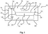
- Fig. 1 shows an apparatus 10 for preparing food.
- the apparatus 10 is a desk-appliance apparatus.
- the apparatus 10 comprises a food preparation chamber 12, an air movement device 14, a heating device 16, and air guiding means.
- the air guiding means are indicated with dotted lines 18 in Fig. 1 , in combination with arrows 20, schematically indicating an air flow.
- the food preparation chamber 12 is provided by a container structure 22 at least partly enclosing a receiving volume 24 for receiving food to be prepared by a through-streaming of hot air.
- the receiving volume 24 is indicated with an upper dotted line.
- the container structure 22 comprises side walls 26 and a bottom wall 28.
- the bottom wall 28 and/or one of the side walls 26 is air-permeable providing an air entry opening, indicated with arrow 30, for entering of hot air into the receiving volume.
- the air entry opening 30 may be provided across the whole surface of the bottom wall 28, or in selected areas.
- the container structure comprises an air discharge opening, as indicated with upper arrow 32.
- the air discharge opening may be provided by an opening across the whole upper surface, as shown in Fig. 1 .
- the heating device 16 is configured to heat air of an air flow provided by the air movement device 14.
- the air guiding means 18 provide an air duct arrangement 34 from the discharge opening 32 via the heating device 16 and the air movement device 14 to the air entry opening 30.
- the air movement device 14 is a fan 36 with an air inlet 38 and an air outlet 40.
- the fan 36 is provided sidewards of the food preparation chamber 12. It is noted that according to the example shown in Fig. 1 , the heating device 16 is provided sidewards of the food preparation chamber 12. However, also other arrangements can be provided, for example indicated with dotted circles 42, indicating a location of the heating device 16 above the food preparation chamber 12.
- the heating device 16 is arranged out-of-sight of the receiving volume 24.
- An outer frame structure indicates a possible housing enclosing the apparatus 10 for preparing food.
- the housing can be provided with an insert opening for filling food into the food preparation chamber 12, which will also be described in more detail in relation with other figures below.
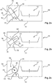
- a fan 44 is provided which has an air suction side 46 and an air blowout side 48. It is noted that next to the air suction side 46, an arrow is shown indicating air being sucked in on the air suction side. In use, the air is blown out at the air blowout side with a mean blowing direction 50.
- the mean blowing direction 50 is provided with a tilted angle 52 to both the horizontal and the vertical.
- the horizontal is referred to as a horizontal portion 54 of a housing structure 55
- the vertical is referred to as a vertical portion 56 of the housing structure 55.
- Fig. 2A shows an example of the fan 44 as a centrifugal fan 58 with an axial air inlet direction aligned with the arrow 46, and a radial air outlet, aligned with the arrow 48.
- a line 60 is indicating an axis of rotation.
- Fig. 2B shows the fan 44 as an axial fan with an axial air inlet, aligned with arrow 46, and an axial air outlet, aligned with the arrow 48.
- the axial fan 62 comprises a fan rotating around a rotating axis 64.
- the rotating axis 64 is provided with a titled angle to both the horizontal and the vertical, similar to the tilted angle 52.
- the fan 44 is provided sidewards of the food preparation chamber when the food preparation chamber is in use.
- Fig. 2C shows the fan 44 in form of a cross-flow blower or cross-flow fan 66 with a rotating structure rotating around a rotating axis 68, i.e. a cylinder like structure that is perpendicular to the drawing plane.
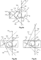
- Fig. 3 shows a further example, wherein the fan 44 is a centrifugal fan 70 inside a fan housing with an axial air inlet 72 and a radial air outlet 74.
- the centrifugal fan comprises a fan 76 rotating in a rotating plane 78 around a rotating axis 80.
- the rotating plane 78 is provided with a tilted angle, for example angle 82, to both the horizontal and the vertical.
- the centrifugal fan provides an integrated guiding of an air stream coming from a first direction and leaving in a second direction, wherein the second direction differs from the first direction by approximately 30° to 120°, for example approximately 90°.
- the tilted angle is provided such that a deflection or guidance of the air flow coming from the air movement device 14 is necessary in an amount of less than 90° in order to reach the area below the food preparation chamber 12.
- the tilted angle comprises an angle to the horizontal in a range of approximately 10° to 80°.
- the angle is provided in a range of approximately 30° to 60°, for example approximately 45°.
- the apparatus 10 is indicated by a rectangular frame 100, indicating a housing structure. Further, the food preparation chamber 12 is symbolically shown. Still further, a first line 102 is defined by the rotating axis of a centrifugal fan, which is not further shown. A second line 104 is arranged perpendicular to the first line 102 in the rotating plane, as mentioned above. A third line 106 is perpendicular to the bottom wall 28 and running through a centre of the bottom wall 28.
- the first line 102, the second line 104, and the third line 106 are arranged in one plane and form a triangle 108 provided by a first section 110 of the first line 102, the first section 110 extending from the intersection of the first line 102 with the second line 104 to the intersection of the first line 102 with the third line 106.
- the triangle 108 is further defined by a second section 112 of the second line 104, the second section 112 reaching from the intersection of the second line 104 with the first line 102 to the intersection of the second line 104 with the intersection of the third line 106.
- a third section 114 of the third line 106 is defined, the third section 114 extending from an intersection of the third line 106 with the first line 102 to an intersection of the third line 106 with the second line 104.
- An inner circle 116 of the triangle 108 is arranged inside the housing structure 100 of the apparatus.
- the first and the second line have an intersection point 118 that is arranged in a middle region of the height of the housing structure.
- the height is indicated with a double arrow 120.
- the inner circle 116 has a maximum diameter 122.
- the "middle region” relates to a height arranged in the middle third of the height.
- the arrangement of the intersection in the middle of the height allows a maximum diameter of a fan, e.g. a centrifugal fan.
- Fig. 4B shows a further possible arrangement of the first line 102, the second line 104, and the third line 106, wherein the first line 102 and the second line 104 are maintained perpendicular to each other, but tilted together in relation to the third line 106, namely approximately 10° to 30° in a clockwise direction.
- a first dotted line 124 indicates the position of the first line 102 of Fig. 4A
- a second dotted line 126 indicates the position of the second line 104 of Fig. 4A .
- the first line 102, the second line 104, and the third line 106 form a triangle, however with different proportion compared to Fig. 4A .
- An inner circle of the triangle with a maximum diameter is indicated by a dotted circle 128.
- this inner circle 128 would extend outside of the housing structure 100.
- an inner circle of the triangle arranged inside the housing structure 100 would have to smaller, as indicated with a full line circle 130.
- Fig. 4C shows a further example, in which the first line 102 and the second line 104, being perpendicular to each other, are slightly rotated counter-clockwise, leading to a similar situation, in which the circle 130, i.e. the dotted circle, indicates the inner circle of the triangle, but the circle 128 in straight line shows the maximum diameter of a circle arranged inside the housing structure 100 and as an inner circle of the triangle.
- the circle 130 i.e. the dotted circle
- the degree of angulations of the triangle should be well balanced by providing the first and the second lines 102, 104 with approximately 45° to both the horizontal and the vehicle.
- Fig. 5 shows a further example of the apparatus 10, wherein the heating device 16 is arranged out-of-sight of the receiving volume 24.
- the air movement device 14 is schematically shown.
- the air movement device 14 can be provided in different variations.
- the heating device 16 can also be arranged in different variations, as long as a direct line of sight from the heating device 16 to the receiving volume 24 is omitted, i.e. prevented.
- the heating device 16 is arranged sidewards of the food preparation chamber 12.
- an air duct is provided between the outlet of the fan, e.g. a centrifugal fan, and the air entry opening of the bottom wall, which shall also be described in the following.
- an air duct arrangement comprises a number of guiding portions, in which an air flow direction is changed. It is noted that air guiding portions are also provided by housing parts or elements not further shown in detail which is why they are not labelled with a reference number.
- a simplified circulating air flow 140 is indicated. For example, hot air exiting from the air movement device 14 is slightly changing its direction due to the guiding portion 138. Further, the air flow is changing its direction below the bottom wall 28, as indicated with bending portion 140. Following, the air flow streams through food to be prepared and upon exiting the food, i.e.
- a further change of direction as indicated by a further bending portion 144, is provided.
- a further bending portion 146 indicates a further guiding portion.
- a bending portion 148 arranged inside the air movement device 14 indicates that a further change of airflow direction is provided.
- a first guiding portion for example the guiding portion 138
- a second guiding portion for example the guiding portion 146
- the first guiding portion 138 provides a lower degree of change of direction of the air flow than the second guiding portion 146.
- the guiding portion with the sharpest bent for the air flow is provided at the suction side of the air movement device, e.g. the fan.
- the least sharp bent is provided near the air movement device outlet.
- the second guiding portion provides a maximum degree of change of direction of the air flow
- the first guiding portion provides a minimum degree of change of direction of the air flow
- the guiding portions are providing minimum number of bents for a maximum air flow, i.e. providing minimized air flow resistance.
- the air duct arrangement is provided with guiding portions that provide a sum of bents of approximately 360°.
- the housing structure 100 comprises an upper opening 150 for inserting the container structure 22 from a top.
- a cover device 152 for example a lid, is provided for closing the opening 150 during food preparation.
- the container structure 22 is provided as a removable pot or basket 154 with a handle bar or a grip portion 156 for easier handling.
- sensor means 160 are provided in relation with the air movement device 14 for detecting air temperature of the air stream supplied by air movement device 14.
- the sensor means 160 are sensors arranged inside a housing structure of the air movement device 14.
- the sensor means may also be provided downstream the air movement device between the air outlet and the bottom wall of the container structure. The sensors can detect if the air heated by the heating device gets too hot, due to a malfunction of the heating device, for example.
- a removable pan structure 170 is provided at least partly below the food preparation chamber.
- the food preparation chamber 12 is at least partly inserted into the removable pan structure 170.
- An air-guiding duct 172 is provided between the removable pan structure 170 and the bottom wall 28.
- the air-guiding duct 172 is provided for guiding heated air stream from the air outlet, for example the radial air outlet 74, to the air entry opening 30.
- the air-guiding duct is provided by the removable pan structure and the bottom wall as the physical features; the food preparation chamber relates to the space or area defined by the container walls that are enclosing the food preparation chamber at least partly.
- the removable pan structure is provided as one removable pan. In another example, two or more removable pans are provided.
- a non-removable pan structure for example a pan fixed to the housing, and a separately removable small oil and particle collection container is provided.
- Fig. 3 shows the different aspects described above in a single embodiment, it is provided that, for example, the aspect of the guiding portions, the aspect of the sensor means, the aspect of the centrifugal fan, the aspect of the removal pan structure can be provided in combination with the respective other features, or also without the respective other features, i.e. in different varying combinations.
- out-of-sight relates to an arrangement where a direct (linear) line between the heating device and the receiving volume, i.e. in particular the food arranged in the receiving volume, is not possible, because the direct connection line is blocked by other structural parts.
- the thermal energy provided by the heating device is predominantly transferred via heat convection.
- the air flow is transporting and transmitting the thermal energy to the food to be prepared.
- some of the radiation from the heating device may be reflected by the lid, for example. Nevertheless, the resulting energy flow in form of this radiated heat is much lower than the convection part.
- the heating device is arranged in a concealed manner with respect to the food being prepared.
- a side wall shades off radiated heat from the heating device with respect to the receiving volume, i.e. the side wall is a barrier with respect to direct line of connection between the heating device and the receiving volume. This avoids that the food is heated by direct radiation from the heating device, but only by heat provided by the generated heated air. Nevertheless, a reflector on top of the food may be provided for an improved use of the thermal energy provided to the food by the heated air.
- the receiving volume does not experience any heat transfer by direct radiation from the heating device.
- the "air movement device” is also referred to as a fan device or a ventilation device.
- the air movement device provides movement of heated air in a circulating fashion for heating the food to be prepared.
- the air movement device provides movement of the air without varying other air parameter, in one example.
- the air movement device also provides influencing or adjusting other air properties/parameters, such as humidity, oxygen content, ratio of reused air and fresh air input, for example.
- the heated air may be provided to food having different insertion temperatures.
- the resulting air flow may be a temperature below 0 °C, at least for the first time span, e.g.
- the air temperature may reach 140 °C to 200 °C or more.
- the air temperature may be adjustable, depending on the type of food.
- the container structure may enclose the food preparation chamber partly in form of a pot or pan by providing a bottom wall and a surrounding continuous side wall, or a number of side walls.
- the container structure may enclose the food preparation chamber completely in form of a closed pot or pan by providing not only a bottom wall and a side wall, but also a closing upper structure such as a lid or cover.
- provisions are taken to let a stream of heated air entering the food preparation chamber, i.e. via the air entry opening, and also to let the air exiting the food preparation chamber, i.e. via the air discharge opening.
- opening in relation with the air stream relate to the capability of air passing through. This may be provided, for example, by a sieve, grid, or mesh-like structure.
- heated air relates to air heated up to temperature range of approximately 80 to 200 °C at the end, or the temperature peak, of the food preparation process.
- the air may be provided with different amounts of relative humidity. For example, a relative humidity range of 5 to 100% may be provided.
- sidewards of the food preparation chamber refers to an arrangement of the air movement device on the side or besides the food preparation chamber in a horizontal direction.
- the air movement device is located next to side walls of the food preparation chamber.
- the air movement device may also be located sidewards in a horizontal direction and displaced upwards, such that the air movement device extends above the container structure.
- the horizontal relates to a horizontal plane or axis, when in normal operation.
- the vertical relates to a respective vertical plane or axis.
- the term horizontal relates to a desk surface or working surface, for example in a kitchen.
- the term vertical relates to a perpendicular line with regard to the horizontal.
- the air discharge opening 32 is provided by side wall portions of the container structure 22.
- the discharge opening 32 is provided as an upwardly oriented opening of the container structure 22. In another example, the discharge opening 32 is provided by side wall portions of the container structure 22.
- bottom wall refers to a wall segment or wall area provided in the lower part, facing downwards in a normal operation state.
- side walls also refers to a side wall arrangement with a continuous side wall or a plurality of side wall segments.
- the term "axial air inlet” relates to an air inlet or suction opening of the air movement device, for example provided in the vicinity of the rotating axis of the centrifugal fan, or in the vicinity of the rotating axis of an axial fan.
- the air inlet may be provided between the rotating axis and the circumference described by rotating blades (or vanes) of the centrifugal fan.
- the air movement device is provided downstream of the heating device.
- the heating device is provided downstream of the air movement device.
- heating is provided upstream and downstream of the air movement device.
- the air outlet may be provided as a radial air outlet, as already mentioned above. However, the air may be blown out also with a tangential movement component.
- the receiving volume 24 is a sub-volume (i.e. a part of the volume) of the food preparation chamber 12.
- the tilted arranged of the air movement device 14 provides the effect that a circulating part of the air flow is provided with a minimized degree of bents of the air duct or air path, and the sharpest bent is located at the air inlet of the fan. This means a minimized resistance for the air flow, and thus improves the air flow rate.
- Fig. 6 shows a further example, wherein a collecting device 180 with a collection volume 182 is provided below the food preparation chamber 12 for collecting residual material.
- residual material refers to, for example, oil, and particles.
- an air guiding element 184 is provided that directs a horizontal air flow 186 below the container structure 22 in an upwards direction towards the air entry opening 30.
- the collecting device 180 is arranged besides the air guiding element 184 on a side 188 facing away from the horizontal air flow 186.
- the collecting device 180 is arranged on the leeside of the air guiding element, i.e. the air guiding element is providing shading of the heated air stream.
- the collecting device is provided by at least one recess in the removable or detachable pan.
- the recess in the removable pan is provided with a drainage opening, and a removable collecting receptacle is provided below the opening (not further shown).
- the collecting device is provided as a separate inlay placed into a recess of the removable pan (also not further shown).
- Fig. 7 shows a further example in a cross-section in Fig. 7A , and a perspective view in Fig. 7B .
- An air-distributing duct 190 is provided below the air entry opening 30 of the bottom wall 28.
- An air guide 192 is provided as an elevation arranged on a lower surface 194 of the air distributing duct 190 below the air entry opening 30.
- the elevation is extending across the cross-section of the air distributing duct 190.
- the elevation is extending across at least a third of the cross-section, for example in one section or also in separated sections.
- the elevation is extending across at least half of the cross-section.
- the elevation is extending across the whole width of the cross-section, as shown in Fig. 7B .
- the air guide 192 is arranged in a skewed manner, indicated with an angle 196 between the linear extension indicated with a first dotted line 198, and a perpendicular (or rectangular angle of the general or mean direction of the air distributing duct, which perpendicular is indicated with a second dotted line 200.
- the air guide is arranged in the skewed manner 196 in relation to a perpendicular direction of an out-blowing direction of an air outlet such that below the air entry opening 30, an evenly distributed air flow is provided. This is indicated with three air stream indicating arrows 202 in Fig. 7B .
- the "skewed manner” relates to an angle of at least 5° or 10° to the perpendicular direction of the out-blowing direction.
- the "out-blowing direction” relates to a central air flow direction of the blown out air stream.
- the elevation may be extending over the complete cross-section of the width, as mentioned above, or also only over a part.
- the air guide 192 can be provided as linear air guide, as shown. In another example (not shown), the air guide is provided in a curved manner.
- Fig. 8 shows a further example, wherein a flow spreader 210 is provided between the air outlet 212 of the air movement device 14 and an air distribution zone 214 provided below the air entry opening 30 of the bottom wall 28.
- the flow spreader is provided as a duct segment 216 with a decreasing cross-section, indicated with double arrow 218, across an air passage direction to compensate for an asymmetrical air output of the air outlet.
- the flow spreader is provided as an inclined wall of an air duct.
- the bottom wall segment is inclined in relation to the horizontal.
- a rip structure is provided in the duct segment 216.
- the inclined wall has a tilted angle in relation to the horizontal that is smaller than the tilted angle of the rotating plane in relation with the horizontal.
- a first angle 220 indicates the angle of the rotating plane in relation with the horizontal
- a second angle 222 indicates an angle of the inclined wall, for example wall segment 224, with the horizontal.
- the second angle is smaller than the first angle.
- Fig. 9 shows an example of a method 300 for preparing food, for example in a desk-appliance apparatus, comprising the following steps:
- a first step 302 food is provided in a food preparation chamber provided by a container structure at least partly enclosing a receiving volume for receiving the food to be prepared.
- a through-streaming of hot air is provided in the food preparation chamber.
- the through-streaming of hot air is provided by an air movement device and a heating device.
- a circulating air flow is provided by air guiding means providing an air duct arrangement from the discharge opening of the container structure via the heating device and the air movement device to an air entry opening of the container structure.
- a fan with an air inlet and an air outlet is provided, wherein the fan is provided sidewards of the food preparation chamber.
- the first step 302 is also referred to as step a), and the second step 304 as step b).
- the air is heated by the heating device that is arranged out-of-sight of the receiving volume, in a further example.
Landscapes
- Engineering & Computer Science (AREA)
- Food Science & Technology (AREA)
- Life Sciences & Earth Sciences (AREA)
- Health & Medical Sciences (AREA)
- Nutrition Science (AREA)
- Chemical & Material Sciences (AREA)
- Polymers & Plastics (AREA)
- Baking, Grill, Roasting (AREA)
Claims (15)
- Appareil (10) pour la préparation de nourriture, comprenant :- une chambre de préparation de nourriture (12) ;- un dispositif de mouvement d'air (14) ;- un dispositif de chauffage (16) ; et- un moyen de guidage d'air (18) ;dans lequel la chambre de préparation de nourriture est fournie par une structure de conteneur (22) entourant au moins partiellement un volume de réception (24) pour recevoir de la nourriture devant être préparée ; dans lequel la structure de conteneur comprend des parois latérales (26), une paroi inférieure (28) et une surface supérieure, dans lequel la paroi inférieure et/ou une des parois latérales est perméable à l'air fournissant une ouverture d'entrée d'air (30) pour l'entrée d'air dans le volume de réception, et dans lequel la structure de conteneur comprend une ouverture d'évacuation d'air (32) sur la surface supérieure ;
dans lequel le dispositif de mouvement d'air est un ventilateur (36) avec une arrivée d'air (38) et une sortie d'air (40) ; dans lequel le ventilateur est fourni sur le côté de la chambre de préparation de nourriture ; et dans lequel le dispositif de chauffage est configuré pour chauffer de l'air d'un flux d'air fourni par le dispositif de mouvement d'air ;
caractérisé en ce que
le moyen de guidage d'air fournit un agencement de conduite d'air (34) depuis l'ouverture d'évacuation par l'intermédiaire du dispositif de chauffage et du dispositif de mouvement d'air vers l'ouverture d'entrée d'air ;
en ce que le dispositif de chauffage (16) est sur le côté de, ou au-dessus de, la chambre de préparation de nourriture ; et
en ce que, durant le fonctionnement de l'appareil, la nourriture est préparée par un flux traversant d'air chaud, c.-à-d. par la distribution de chaleur sur la nourriture par de l'air chaud, fourni par le dispositif de mouvement d'air et le dispositif de chauffage. - Appareil selon la revendication 1, dans lequel, comme dispositif de mouvement d'air, un ventilateur est fourni qui possède un côté d'aspiration d'air (46) et un côté de rejet d'air (48) ;
dans lequel, en utilisation, l'air est rejeté du côté de rejet d'air avec une direction de rejet moyenne (50) ; et
dans lequel la direction de rejet moyenne est fournie avec un angle incliné (52) vers à la fois l'horizontale et la verticale. - Appareil selon la revendication 1 ou 2, dans lequel le ventilateur est un ventilateur centrifuge (70) à l'intérieur d'un boîtier de ventilateur avec une arrivée d'air axiale (72) et une sortie d'air radiale (74) ;
dans lequel le ventilateur centrifuge comprend un ventilateur (76) pivotant dans un plan de rotation (78) ; et
dans lequel le plan de rotation est fourni avec un angle incliné (82) vers à la fois l'horizontale et la verticale. - Appareil selon la revendication 2 ou 3, dans lequel l'angle incliné comprend un angle vers l'horizontale dans une gamme d'environ 10 ° à 80 .
- Appareil selon l'une des revendications précédentes, dans lequel :- une première ligne (102) est définie par l'axe de rotation,- une deuxième ligne (104) est agencée perpendiculairement à la première ligne dans le plan de rotation, et- une troisième ligne (106) est perpendiculaire à la paroi inférieure et traverse un centre de la paroi inférieure ;dans lequel la première ligne, la deuxième ligne et la troisième ligne sont agencées dans un plan et forment un triangle (108) ; et
dans lequel un cercle intérieur (116) du triangle est agencé à l'intérieur d'une structure de boîtier (100) de l'appareil ;
dans lequel la première et la deuxième ligne ont un point d'intersection (118) qui est agencé dans une région médiane de la hauteur de la structure de boîtier ; et
dans lequel le cercle intérieur a un diamètre maximal (122). - Appareil selon l'une des revendications précédentes, dans lequel l'appareil est un appareil de bureau.
- Appareil selon l'une des revendications précédentes,
dans lequel le dispositif de chauffage est agencé en dehors du champ de vision du volume de réception. - Appareil selon l'une des revendications précédentes, dans lequel le dispositif de chauffage est agencé sur le côté de la chambre de préparation de nourriture.
- Appareil selon l'une des revendications précédentes, dans lequel un agencement de conduite d'air comprend un nombre de parties de guidage (138), dans lesquelles une direction de flux d'air est changée ;
dans lequel une première partie de guidage (138) est fournie en aval derrière le dispositif de mouvement d'air, et une deuxième partie de guidage est fournie en amont devant le dispositif de mouvement d'air ; et
dans lequel la première partie de guidage fournit un degré inférieur de changement de direction du flux d'air que la deuxième partie de guidage. - Appareil selon l'une des revendications précédentes, dans lequel un moyen de capteur (160) est fourni en relation avec le dispositif de mouvement d'air pour détecter une température d'air du courant d'air fourni par le dispositif de mouvement d'air.
- Appareil selon l'une des revendications précédentes, dans lequel :- une structure de casserole amovible (170) est fourni au moins partiellement en dessous de la chambre de préparation de nourriture ; et dans laquelle une conduite de guidage d'air (172) entre la structure de casserole amovible et la paroi inférieure est fournie par la structure de casserole amovible pour guider un courant d'air chauffé depuis la sortie d'air vers l'ouverture d'entrée d'air ; et/ou- dans lequel un dispositif de collecte (180) avec un volume de collecte (182) est fourni en dessous de la chambre de préparation de nourriture pour collecter de la matière résiduelle.
- Appareil selon la revendication 11, dans lequel un élément de guidage d'air (184) est fourni qui dirige un flux d'air horizontal (186) en dessous de la structure de conteneur dans une direction ascendante vers l'ouverture d'entrée d'air ; et
dans lequel le dispositif de collecte est agencé à côté de l'élément de guidage d'air sur un côté (188) faisant face à l'opposé du flux d'air horizontal. - Appareil selon l'une des revendications précédentes, dans lequel une conduite de distribution d'air (190) est fournie en dessous de l'ouverture d'entrée d'air de la paroi inférieure ;
dans lequel un guide d'air (192) est fourni comme une élévation agencée sur une surface inférieure (194) de la conduite de distribution d'air en dessous de l'ouverture d'entrée d'air ; et
dans lequel le guide d'air est agencé d'une manière oblique (196) par rapport à une direction perpendiculaire d'une direction de rejet de la sortie d'air de sorte que, en dessous de l'ouverture d'entrée d'air, un flux d'air uniformément distribué soit fourni. - Appareil selon l'une des revendications précédentes, dans lequel un répartiteur de flux (210) est fourni entre la sortie d'air et une zone de distribution d'air (214) fournie en dessous de l'ouverture d'entrée d'air de la paroi inférieure ;
dans lequel le répartiteur de flux est fourni comme un segment de conduite (216) avec une section transversale décroissante (218) à travers une direction de passage d'air pour compenser une sortie d'air asymétrique de la sortie d'air. - Procédé (300) pour préparer de la nourriture dans l'appareil selon l'une des revendications 1 à 14, le procédé comprenant les étapes suivantes :a) fournir (302) de la nourriture dans une chambre de préparation de nourriture fournie par une structure de conteneur entourant au moins partiellement un volume de réception pour recevoir la nourriture devant être préparée ;b) préparer (304) la nourriture dans la chambre de préparation en utilisant un dispositif de mouvement d'air, plus particulièrement un ventilateur avec une arrivée d'air et une sortie d'air, le ventilateur étant fourni sur le côté de la chambre de préparation de nourriture, et un dispositif de chauffage ;
caractérisé en ce que :un flux d'air circulant est fourni par un moyen de guidage d'air fournissant un agencement de conduite d'air depuis une ouverture d'évacuation de la structure de conteneur qui est au niveau d'une surface supérieure de la structure de conteneur par l'intermédiaire du dispositif de chauffe et du dispositif de mouvement d'air vers une ouverture d'entrée d'air de la structure de conteneur qui est dans une paroi inférieure et/ou dans une des parois latérales de la structure de conteneur ;la nourriture est préparée par un flux traversant d'air chaud fourni par le dispositif de mouvement d'air et le dispositif de chauffage ; etle chauffage par le dispositif de chauffage (16) pour produire l'air chaud est effectué sur le côté de, ou au-dessus de, la chambre de préparation de nourriture.
Priority Applications (1)
| Application Number | Priority Date | Filing Date | Title |
|---|---|---|---|
| EP14726980.7A EP3003106B1 (fr) | 2013-06-04 | 2014-05-28 | Friteuse à air |
Applications Claiming Priority (3)
| Application Number | Priority Date | Filing Date | Title |
|---|---|---|---|
| EP13170423 | 2013-06-04 | ||
| EP14726980.7A EP3003106B1 (fr) | 2013-06-04 | 2014-05-28 | Friteuse à air |
| PCT/EP2014/061006 WO2014195192A1 (fr) | 2013-06-04 | 2014-05-28 | Appareil de friture à air |
Publications (2)
| Publication Number | Publication Date |
|---|---|
| EP3003106A1 EP3003106A1 (fr) | 2016-04-13 |
| EP3003106B1 true EP3003106B1 (fr) | 2019-10-02 |
Family
ID=48569969
Family Applications (1)
| Application Number | Title | Priority Date | Filing Date |
|---|---|---|---|
| EP14726980.7A Active EP3003106B1 (fr) | 2013-06-04 | 2014-05-28 | Friteuse à air |
Country Status (6)
| Country | Link |
|---|---|
| US (1) | US9980605B2 (fr) |
| EP (1) | EP3003106B1 (fr) |
| JP (1) | JP6416892B2 (fr) |
| CN (2) | CN204260584U (fr) |
| BR (1) | BR112015030164B1 (fr) |
| WO (1) | WO2014195192A1 (fr) |
Families Citing this family (37)
| Publication number | Priority date | Publication date | Assignee | Title |
|---|---|---|---|---|
| EP3003104B1 (fr) * | 2013-06-04 | 2019-09-18 | Koninklijke Philips N.V. | Friteuse à air |
| CN104770418B (zh) * | 2015-04-14 | 2017-03-01 | 东莞市金玛电器有限公司 | 新型空气炸锅 |
| PL3162259T3 (pl) * | 2015-11-02 | 2019-07-31 | Koninklijke Philips N.V. | Człon prowadzący powietrze dla urządzenia wykorzystującego strumień powietrza do przygotowywania składników żywności |
| CN108778074B (zh) * | 2016-03-09 | 2022-06-24 | 皇家飞利浦有限公司 | 空气炸锅及空气炸锅的清洁方法 |
| CN107343741B (zh) * | 2016-05-06 | 2023-01-10 | 深圳市联创三金电器有限公司 | 利用热空气循环制备食物的装置 |
| CN205963849U (zh) * | 2016-05-24 | 2017-02-22 | 飞利浦(中国)投资有限公司 | 空气炸锅 |
| CN107510379B (zh) * | 2016-06-15 | 2022-07-15 | 皇家飞利浦有限公司 | 空气炸锅 |
| RU2737519C2 (ru) | 2016-06-15 | 2020-12-01 | Конинклейке Филипс Н.В. | Мультипечь |
| CN110167403A (zh) * | 2016-09-02 | 2019-08-23 | 品谱公司 | 用于面包烤箱的热量分布构件和通气口 |
| CN107928440A (zh) * | 2016-10-13 | 2018-04-20 | 深圳市联创三金电器有限公司 | 利用热空气制作食物的设备 |
| CA3065773C (fr) | 2017-08-09 | 2021-02-09 | Sharkninja Operating Llc | Dispositif de cuisson et composants de celui-ci |
| USD914436S1 (en) | 2018-06-19 | 2021-03-30 | Sharkninja Operating Llc | Air diffuser with food preparation pot |
| CN108577581A (zh) * | 2018-06-21 | 2018-09-28 | 深圳市明翔电器有限公司 | 一种加热均匀的空气炸锅 |
| CN108720641B (zh) * | 2018-06-22 | 2023-09-08 | 伊立浦集团股份有限公司 | 烤箱 |
| USD883014S1 (en) | 2018-08-09 | 2020-05-05 | Sharkninja Operating Llc | Food preparation device |
| USD934027S1 (en) | 2018-08-09 | 2021-10-26 | Sharkninja Operating Llc | Reversible cooking rack |
| USD903413S1 (en) | 2018-08-09 | 2020-12-01 | Sharkninja Operating Llc | Cooking basket |
| USD883015S1 (en) | 2018-08-09 | 2020-05-05 | Sharkninja Operating Llc | Food preparation device and parts thereof |
| EP3682775A1 (fr) * | 2019-01-17 | 2020-07-22 | Koninklijke Philips N.V. | Appareil de cuisson |
| US11051654B2 (en) | 2019-02-25 | 2021-07-06 | Sharkninja Operating Llc | Cooking device and components thereof |
| EP4714316A2 (fr) | 2019-02-25 | 2026-03-25 | SharkNinja Operating LLC | Système de cuisson avec protection |
| USD982375S1 (en) | 2019-06-06 | 2023-04-04 | Sharkninja Operating Llc | Food preparation device |
| USD918654S1 (en) | 2019-06-06 | 2021-05-11 | Sharkninja Operating Llc | Grill plate |
| EP3838086A1 (fr) | 2019-12-19 | 2021-06-23 | Koninklijke Philips N.V. | Friteuse à air configurable et son procédé de fonctionnement |
| CN113133684B (zh) * | 2020-01-17 | 2023-10-24 | 广东美的生活电器制造有限公司 | 空气炸锅 |
| NL2024781B1 (en) * | 2020-01-28 | 2021-09-09 | Kavaring Cooking Systems B V | Airfrying system and method |
| US11134808B2 (en) | 2020-03-30 | 2021-10-05 | Sharkninja Operating Llc | Cooking device and components thereof |
| CN113966962A (zh) | 2020-07-22 | 2022-01-25 | 即时品牌公司 | 空气烹饪装置 |
| CN213248568U (zh) | 2020-08-10 | 2021-05-25 | 即时品牌公司 | 空气烹饪装置 |
| CN114098459A (zh) | 2020-09-01 | 2022-03-01 | 即时品牌公司 | 空气烹饪装置 |
| EP4018892A1 (fr) * | 2020-12-22 | 2022-06-29 | Koninklijke Philips N.V. | Appareil de cuisson |
| CN112790623B (zh) * | 2021-03-01 | 2022-08-23 | 广东美的厨房电器制造有限公司 | 热风组件及烹饪装置 |
| US20220316711A1 (en) * | 2021-04-05 | 2022-10-06 | Whirlpool Corporation | Heating apparatus |
| CN113633193B (zh) * | 2021-09-08 | 2023-01-31 | 广东美的厨房电器制造有限公司 | 壳体组件及具有其的烹饪器具 |
| CN113842061A (zh) * | 2021-09-28 | 2021-12-28 | 小熊电器股份有限公司 | 空气烹饪器具 |
| US11882961B1 (en) | 2023-01-18 | 2024-01-30 | Sharkninja Operating Llc | Cover plate for cooking devices |
| USD1083485S1 (en) | 2023-08-29 | 2025-07-15 | Sharkninja Operating Llc | Stacked air fryer |
Family Cites Families (21)
| Publication number | Priority date | Publication date | Assignee | Title |
|---|---|---|---|---|
| US2966573A (en) * | 1960-12-27 | hansen | ||
| US4374319A (en) * | 1979-11-27 | 1983-02-15 | Sunset Ltd. | Counter-top oven |
| US4295419A (en) * | 1980-05-12 | 1981-10-20 | Larry Poulson | Confined air food heating apparatus |
| US4728762A (en) * | 1984-03-22 | 1988-03-01 | Howard Roth | Microwave heating apparatus and method |
| EP0495034A1 (fr) * | 1990-08-07 | 1992-07-22 | HOEBERGIS, Jean M. M. | Agencement servant a frire ou a rechauffer les denrees alimentaires |
| US5671660A (en) * | 1994-12-12 | 1997-09-30 | Moshonas; Georges | Heated air-circulating oven |
| ATE384415T1 (de) | 2000-11-30 | 2008-02-15 | Lg Electronics Inc | Heizvorrichtung für einen mikrowellenherd |
| DE20214744U1 (de) | 2002-09-24 | 2004-02-19 | Apparatebau Gmbh, Laag | Vorrichtung zum Frittieren von Nahrungsmitteln |
| DK1686880T3 (da) * | 2003-11-21 | 2009-03-16 | Soparfin Sa | Indretning til at opvarme födevarer med varm luft |
| JP2006003030A (ja) | 2004-06-18 | 2006-01-05 | Matsushita Electric Ind Co Ltd | 加熱調理器 |
| KR100743347B1 (ko) | 2005-07-12 | 2007-07-26 | 강규석 | 로스터의 공기 순환시스템 |
| EP1867264A1 (fr) * | 2006-06-16 | 2007-12-19 | Kavaring Cooking Systems B.V. i.o. | Appareil pour la préparation de produits alimentaires |
| GB2481553B (en) * | 2007-10-09 | 2012-02-15 | Acp Inc | Temperature control for cooking appliance including combination heating system |
| US20090324781A1 (en) | 2008-06-30 | 2009-12-31 | Soudry Jonathan N | Apparatus and method of toasting sandwiches without heating the sandwich filling |
| ES2565642T3 (es) | 2008-09-23 | 2016-04-06 | Koninklijke Philips N.V. | Aparato para la preparación de alimentos y elemento de guía de aire para el mismo |
| KR100933522B1 (ko) | 2009-02-07 | 2009-12-23 | 주식회사 엔유씨전자 | 탈취/연기제거 기능을 갖는 가열조리기 |
| FR2944672B1 (fr) | 2009-04-27 | 2011-08-05 | Seb Sa | Procede de friture rapide adapte a l'utilisation d'une faible quantite de matiere grasse, et appareil utilisant ledit procede |
| FR2945200B1 (fr) | 2009-05-05 | 2016-02-05 | Seb Dev | Appareil de cuisson avec moyen de remuage |
| ATE539665T1 (de) | 2009-05-27 | 2012-01-15 | De Longhi Appliances Srl | Frittiergerät und verfahren zum kochen mit einer geringen ölmenge |
| MX2013002576A (es) | 2010-09-10 | 2013-04-03 | Koninkl Philips Electronics Nv | Aparato para preparacion de alimento. |
| CN202374954U (zh) * | 2011-12-09 | 2012-08-15 | 胡培德 | 无烟调温碳烧烤炉 |
-
2014
- 2014-05-28 US US14/895,981 patent/US9980605B2/en active Active
- 2014-05-28 WO PCT/EP2014/061006 patent/WO2014195192A1/fr not_active Ceased
- 2014-05-28 EP EP14726980.7A patent/EP3003106B1/fr active Active
- 2014-05-28 BR BR112015030164-9A patent/BR112015030164B1/pt active IP Right Grant
- 2014-05-28 JP JP2016517238A patent/JP6416892B2/ja not_active Expired - Fee Related
- 2014-06-04 CN CN201420295279.6U patent/CN204260584U/zh not_active Expired - Lifetime
- 2014-06-04 CN CN201410245931.8A patent/CN104207657B/zh active Active
Non-Patent Citations (1)
| Title |
|---|
| None * |
Also Published As
| Publication number | Publication date |
|---|---|
| CN204260584U (zh) | 2015-04-15 |
| JP6416892B2 (ja) | 2018-10-31 |
| CN104207657A (zh) | 2014-12-17 |
| BR112015030164B1 (pt) | 2021-05-25 |
| US20160113442A1 (en) | 2016-04-28 |
| JP2016519992A (ja) | 2016-07-11 |
| WO2014195192A1 (fr) | 2014-12-11 |
| EP3003106A1 (fr) | 2016-04-13 |
| CN104207657B (zh) | 2019-10-15 |
| BR112015030164A2 (pt) | 2017-07-25 |
| US9980605B2 (en) | 2018-05-29 |
Similar Documents
| Publication | Publication Date | Title |
|---|---|---|
| EP3003106B1 (fr) | Friteuse à air | |
| US10264917B2 (en) | Air-based fryer | |
| EP3003107B1 (fr) | Friteuse à air | |
| JP2016519992A5 (fr) | ||
| RU2729221C2 (ru) | Воздухонаправляющий элемент устройства, использующего воздушный поток для приготовления пищевых ингредиентов | |
| EP3590398B1 (fr) | Plat pour friteuse à air | |
| CN103096768B (zh) | 用于制备食品的装置 | |
| US20190298106A1 (en) | An air-based cooker | |
| RU2678373C1 (ru) | Воздухонаправляющий компонент в аэрогриле | |
| CN217510318U (zh) | 烹饪设备 | |
| KR102340541B1 (ko) | 전열 조리기구 | |
| EP4523581A1 (fr) | Friteuse à air avec guidage de flux d'air |
Legal Events
| Date | Code | Title | Description |
|---|---|---|---|
| PUAI | Public reference made under article 153(3) epc to a published international application that has entered the european phase |
Free format text: ORIGINAL CODE: 0009012 |
|
| 17P | Request for examination filed |
Effective date: 20160104 |
|
| AK | Designated contracting states |
Kind code of ref document: A1 Designated state(s): AL AT BE BG CH CY CZ DE DK EE ES FI FR GB GR HR HU IE IS IT LI LT LU LV MC MK MT NL NO PL PT RO RS SE SI SK SM TR |
|
| AX | Request for extension of the european patent |
Extension state: BA ME |
|
| DAX | Request for extension of the european patent (deleted) | ||
| STAA | Information on the status of an ep patent application or granted ep patent |
Free format text: STATUS: EXAMINATION IS IN PROGRESS |
|
| 17Q | First examination report despatched |
Effective date: 20180810 |
|
| GRAP | Despatch of communication of intention to grant a patent |
Free format text: ORIGINAL CODE: EPIDOSNIGR1 |
|
| STAA | Information on the status of an ep patent application or granted ep patent |
Free format text: STATUS: GRANT OF PATENT IS INTENDED |
|
| INTG | Intention to grant announced |
Effective date: 20190430 |
|
| RIN1 | Information on inventor provided before grant (corrected) |
Inventor name: SHRIVASTAVA, ADARSH Inventor name: PASTOORS, MARC ALEXANDER Inventor name: DE HAAS, ROGIER ENRICO Inventor name: WURMITZER, RUDOLF Inventor name: VAN WIFFEREN, REINDERT JANNES Inventor name: ZAINITZER, CHRISTIAN |
|
| GRAS | Grant fee paid |
Free format text: ORIGINAL CODE: EPIDOSNIGR3 |
|
| GRAA | (expected) grant |
Free format text: ORIGINAL CODE: 0009210 |
|
| STAA | Information on the status of an ep patent application or granted ep patent |
Free format text: STATUS: THE PATENT HAS BEEN GRANTED |
|
| AK | Designated contracting states |
Kind code of ref document: B1 Designated state(s): AL AT BE BG CH CY CZ DE DK EE ES FI FR GB GR HR HU IE IS IT LI LT LU LV MC MK MT NL NO PL PT RO RS SE SI SK SM TR |
|
| REG | Reference to a national code |
Ref country code: GB Ref legal event code: FG4D |
|
| REG | Reference to a national code |
Ref country code: CH Ref legal event code: EP Ref country code: AT Ref legal event code: REF Ref document number: 1185258 Country of ref document: AT Kind code of ref document: T Effective date: 20191015 |
|
| REG | Reference to a national code |
Ref country code: DE Ref legal event code: R096 Ref document number: 602014054530 Country of ref document: DE |
|
| REG | Reference to a national code |
Ref country code: IE Ref legal event code: FG4D |
|
| REG | Reference to a national code |
Ref country code: NL Ref legal event code: FP |
|
| REG | Reference to a national code |
Ref country code: LT Ref legal event code: MG4D |
|
| RAP2 | Party data changed (patent owner data changed or rights of a patent transferred) |
Owner name: KONINKLIJKE PHILIPS N.V. |
|
| REG | Reference to a national code |
Ref country code: AT Ref legal event code: MK05 Ref document number: 1185258 Country of ref document: AT Kind code of ref document: T Effective date: 20191002 |
|
| PG25 | Lapsed in a contracting state [announced via postgrant information from national office to epo] |
Ref country code: BG Free format text: LAPSE BECAUSE OF FAILURE TO SUBMIT A TRANSLATION OF THE DESCRIPTION OR TO PAY THE FEE WITHIN THE PRESCRIBED TIME-LIMIT Effective date: 20200102 Ref country code: FI Free format text: LAPSE BECAUSE OF FAILURE TO SUBMIT A TRANSLATION OF THE DESCRIPTION OR TO PAY THE FEE WITHIN THE PRESCRIBED TIME-LIMIT Effective date: 20191002 Ref country code: PT Free format text: LAPSE BECAUSE OF FAILURE TO SUBMIT A TRANSLATION OF THE DESCRIPTION OR TO PAY THE FEE WITHIN THE PRESCRIBED TIME-LIMIT Effective date: 20200203 Ref country code: AT Free format text: LAPSE BECAUSE OF FAILURE TO SUBMIT A TRANSLATION OF THE DESCRIPTION OR TO PAY THE FEE WITHIN THE PRESCRIBED TIME-LIMIT Effective date: 20191002 Ref country code: SE Free format text: LAPSE BECAUSE OF FAILURE TO SUBMIT A TRANSLATION OF THE DESCRIPTION OR TO PAY THE FEE WITHIN THE PRESCRIBED TIME-LIMIT Effective date: 20191002 Ref country code: LV Free format text: LAPSE BECAUSE OF FAILURE TO SUBMIT A TRANSLATION OF THE DESCRIPTION OR TO PAY THE FEE WITHIN THE PRESCRIBED TIME-LIMIT Effective date: 20191002 Ref country code: GR Free format text: LAPSE BECAUSE OF FAILURE TO SUBMIT A TRANSLATION OF THE DESCRIPTION OR TO PAY THE FEE WITHIN THE PRESCRIBED TIME-LIMIT Effective date: 20200103 Ref country code: NO Free format text: LAPSE BECAUSE OF FAILURE TO SUBMIT A TRANSLATION OF THE DESCRIPTION OR TO PAY THE FEE WITHIN THE PRESCRIBED TIME-LIMIT Effective date: 20200102 Ref country code: LT Free format text: LAPSE BECAUSE OF FAILURE TO SUBMIT A TRANSLATION OF THE DESCRIPTION OR TO PAY THE FEE WITHIN THE PRESCRIBED TIME-LIMIT Effective date: 20191002 Ref country code: PL Free format text: LAPSE BECAUSE OF FAILURE TO SUBMIT A TRANSLATION OF THE DESCRIPTION OR TO PAY THE FEE WITHIN THE PRESCRIBED TIME-LIMIT Effective date: 20191002 Ref country code: ES Free format text: LAPSE BECAUSE OF FAILURE TO SUBMIT A TRANSLATION OF THE DESCRIPTION OR TO PAY THE FEE WITHIN THE PRESCRIBED TIME-LIMIT Effective date: 20191002 |
|
| PG25 | Lapsed in a contracting state [announced via postgrant information from national office to epo] |
Ref country code: CZ Free format text: LAPSE BECAUSE OF FAILURE TO SUBMIT A TRANSLATION OF THE DESCRIPTION OR TO PAY THE FEE WITHIN THE PRESCRIBED TIME-LIMIT Effective date: 20191002 Ref country code: HR Free format text: LAPSE BECAUSE OF FAILURE TO SUBMIT A TRANSLATION OF THE DESCRIPTION OR TO PAY THE FEE WITHIN THE PRESCRIBED TIME-LIMIT Effective date: 20191002 Ref country code: RS Free format text: LAPSE BECAUSE OF FAILURE TO SUBMIT A TRANSLATION OF THE DESCRIPTION OR TO PAY THE FEE WITHIN THE PRESCRIBED TIME-LIMIT Effective date: 20191002 Ref country code: IS Free format text: LAPSE BECAUSE OF FAILURE TO SUBMIT A TRANSLATION OF THE DESCRIPTION OR TO PAY THE FEE WITHIN THE PRESCRIBED TIME-LIMIT Effective date: 20200224 |
|
| PG25 | Lapsed in a contracting state [announced via postgrant information from national office to epo] |
Ref country code: AL Free format text: LAPSE BECAUSE OF FAILURE TO SUBMIT A TRANSLATION OF THE DESCRIPTION OR TO PAY THE FEE WITHIN THE PRESCRIBED TIME-LIMIT Effective date: 20191002 |
|
| REG | Reference to a national code |
Ref country code: DE Ref legal event code: R097 Ref document number: 602014054530 Country of ref document: DE |
|
| PG2D | Information on lapse in contracting state deleted |
Ref country code: IS |
|
| PG25 | Lapsed in a contracting state [announced via postgrant information from national office to epo] |
Ref country code: DK Free format text: LAPSE BECAUSE OF FAILURE TO SUBMIT A TRANSLATION OF THE DESCRIPTION OR TO PAY THE FEE WITHIN THE PRESCRIBED TIME-LIMIT Effective date: 20191002 Ref country code: EE Free format text: LAPSE BECAUSE OF FAILURE TO SUBMIT A TRANSLATION OF THE DESCRIPTION OR TO PAY THE FEE WITHIN THE PRESCRIBED TIME-LIMIT Effective date: 20191002 Ref country code: RO Free format text: LAPSE BECAUSE OF FAILURE TO SUBMIT A TRANSLATION OF THE DESCRIPTION OR TO PAY THE FEE WITHIN THE PRESCRIBED TIME-LIMIT Effective date: 20191002 Ref country code: IS Free format text: LAPSE BECAUSE OF FAILURE TO SUBMIT A TRANSLATION OF THE DESCRIPTION OR TO PAY THE FEE WITHIN THE PRESCRIBED TIME-LIMIT Effective date: 20200202 |
|
| PLBE | No opposition filed within time limit |
Free format text: ORIGINAL CODE: 0009261 |
|
| STAA | Information on the status of an ep patent application or granted ep patent |
Free format text: STATUS: NO OPPOSITION FILED WITHIN TIME LIMIT |
|
| PG25 | Lapsed in a contracting state [announced via postgrant information from national office to epo] |
Ref country code: IT Free format text: LAPSE BECAUSE OF FAILURE TO SUBMIT A TRANSLATION OF THE DESCRIPTION OR TO PAY THE FEE WITHIN THE PRESCRIBED TIME-LIMIT Effective date: 20191002 Ref country code: SK Free format text: LAPSE BECAUSE OF FAILURE TO SUBMIT A TRANSLATION OF THE DESCRIPTION OR TO PAY THE FEE WITHIN THE PRESCRIBED TIME-LIMIT Effective date: 20191002 Ref country code: SM Free format text: LAPSE BECAUSE OF FAILURE TO SUBMIT A TRANSLATION OF THE DESCRIPTION OR TO PAY THE FEE WITHIN THE PRESCRIBED TIME-LIMIT Effective date: 20191002 |
|
| 26N | No opposition filed |
Effective date: 20200703 |
|
| PG25 | Lapsed in a contracting state [announced via postgrant information from national office to epo] |
Ref country code: SI Free format text: LAPSE BECAUSE OF FAILURE TO SUBMIT A TRANSLATION OF THE DESCRIPTION OR TO PAY THE FEE WITHIN THE PRESCRIBED TIME-LIMIT Effective date: 20191002 |
|
| PG25 | Lapsed in a contracting state [announced via postgrant information from national office to epo] |
Ref country code: CH Free format text: LAPSE BECAUSE OF NON-PAYMENT OF DUE FEES Effective date: 20200531 Ref country code: LI Free format text: LAPSE BECAUSE OF NON-PAYMENT OF DUE FEES Effective date: 20200531 Ref country code: MC Free format text: LAPSE BECAUSE OF FAILURE TO SUBMIT A TRANSLATION OF THE DESCRIPTION OR TO PAY THE FEE WITHIN THE PRESCRIBED TIME-LIMIT Effective date: 20191002 |
|
| GBPC | Gb: european patent ceased through non-payment of renewal fee |
Effective date: 20200528 |
|
| PG25 | Lapsed in a contracting state [announced via postgrant information from national office to epo] |
Ref country code: LU Free format text: LAPSE BECAUSE OF NON-PAYMENT OF DUE FEES Effective date: 20200528 |
|
| PG25 | Lapsed in a contracting state [announced via postgrant information from national office to epo] |
Ref country code: IE Free format text: LAPSE BECAUSE OF NON-PAYMENT OF DUE FEES Effective date: 20200528 Ref country code: GB Free format text: LAPSE BECAUSE OF NON-PAYMENT OF DUE FEES Effective date: 20200528 |
|
| PG25 | Lapsed in a contracting state [announced via postgrant information from national office to epo] |
Ref country code: MT Free format text: LAPSE BECAUSE OF FAILURE TO SUBMIT A TRANSLATION OF THE DESCRIPTION OR TO PAY THE FEE WITHIN THE PRESCRIBED TIME-LIMIT Effective date: 20191002 Ref country code: CY Free format text: LAPSE BECAUSE OF FAILURE TO SUBMIT A TRANSLATION OF THE DESCRIPTION OR TO PAY THE FEE WITHIN THE PRESCRIBED TIME-LIMIT Effective date: 20191002 |
|
| PG25 | Lapsed in a contracting state [announced via postgrant information from national office to epo] |
Ref country code: MK Free format text: LAPSE BECAUSE OF FAILURE TO SUBMIT A TRANSLATION OF THE DESCRIPTION OR TO PAY THE FEE WITHIN THE PRESCRIBED TIME-LIMIT Effective date: 20191002 |
|
| P01 | Opt-out of the competence of the unified patent court (upc) registered |
Effective date: 20230530 |
|
| REG | Reference to a national code |
Ref country code: NL Ref legal event code: PD Owner name: VERSUNI HOLDING B.V.; NL Free format text: DETAILS ASSIGNMENT: CHANGE OF OWNER(S), ASSIGNMENT; FORMER OWNER NAME: KONINKLIJKE PHILIPS N.V. Effective date: 20231108 |
|
| REG | Reference to a national code |
Ref country code: DE Ref legal event code: R081 Ref document number: 602014054530 Country of ref document: DE Owner name: VERSUNI HOLDING B.V., NL Free format text: FORMER OWNER: KONINKLIJKE PHILIPS N.V., EINDHOVEN, NL |
|
| REG | Reference to a national code |
Ref country code: BE Ref legal event code: PD Owner name: VERSUNI HOLDING B.V.; NL Free format text: DETAILS ASSIGNMENT: CHANGE OF OWNER(S), ASSIGNMENT; FORMER OWNER NAME: KONINKLIJKE PHILIPS N.V. Effective date: 20231130 |
|
| PGFP | Annual fee paid to national office [announced via postgrant information from national office to epo] |
Ref country code: BE Payment date: 20240527 Year of fee payment: 11 |
|
| PGFP | Annual fee paid to national office [announced via postgrant information from national office to epo] |
Ref country code: NL Payment date: 20250526 Year of fee payment: 12 |
|
| PGFP | Annual fee paid to national office [announced via postgrant information from national office to epo] |
Ref country code: DE Payment date: 20250528 Year of fee payment: 12 |
|
| PGFP | Annual fee paid to national office [announced via postgrant information from national office to epo] |
Ref country code: FR Payment date: 20250526 Year of fee payment: 12 |
|
| PGFP | Annual fee paid to national office [announced via postgrant information from national office to epo] |
Ref country code: TR Payment date: 20250515 Year of fee payment: 12 |
|
| REG | Reference to a national code |
Ref country code: BE Ref legal event code: MM Effective date: 20250531 |