EP3002827A1 - Verfahren zur herstellung einer elektrischen verbindung mit einem bündelleiter und endhülse - Google Patents
Verfahren zur herstellung einer elektrischen verbindung mit einem bündelleiter und endhülse Download PDFInfo
- Publication number
- EP3002827A1 EP3002827A1 EP15185709.1A EP15185709A EP3002827A1 EP 3002827 A1 EP3002827 A1 EP 3002827A1 EP 15185709 A EP15185709 A EP 15185709A EP 3002827 A1 EP3002827 A1 EP 3002827A1
- Authority
- EP
- European Patent Office
- Prior art keywords
- bundle conductor
- conductor
- end sleeve
- pressing
- individual conductors
- Prior art date
- Legal status (The legal status is an assumption and is not a legal conclusion. Google has not performed a legal analysis and makes no representation as to the accuracy of the status listed.)
- Granted
Links
Images



Classifications
-
- H—ELECTRICITY
- H01—ELECTRIC ELEMENTS
- H01R—ELECTRICALLY-CONDUCTIVE CONNECTIONS; STRUCTURAL ASSOCIATIONS OF A PLURALITY OF MUTUALLY-INSULATED ELECTRICAL CONNECTING ELEMENTS; COUPLING DEVICES; CURRENT COLLECTORS
- H01R4/00—Electrically-conductive connections between two or more conductive members in direct contact, i.e. touching one another; Means for effecting or maintaining such contact; Electrically-conductive connections having two or more spaced connecting locations for conductors and using contact members penetrating insulation
- H01R4/10—Electrically-conductive connections between two or more conductive members in direct contact, i.e. touching one another; Means for effecting or maintaining such contact; Electrically-conductive connections having two or more spaced connecting locations for conductors and using contact members penetrating insulation effected solely by twisting, wrapping, bending, crimping, or other permanent deformation
- H01R4/18—Electrically-conductive connections between two or more conductive members in direct contact, i.e. touching one another; Means for effecting or maintaining such contact; Electrically-conductive connections having two or more spaced connecting locations for conductors and using contact members penetrating insulation effected solely by twisting, wrapping, bending, crimping, or other permanent deformation by crimping
- H01R4/20—Electrically-conductive connections between two or more conductive members in direct contact, i.e. touching one another; Means for effecting or maintaining such contact; Electrically-conductive connections having two or more spaced connecting locations for conductors and using contact members penetrating insulation effected solely by twisting, wrapping, bending, crimping, or other permanent deformation by crimping using a crimping sleeve
-
- H—ELECTRICITY
- H01—ELECTRIC ELEMENTS
- H01R—ELECTRICALLY-CONDUCTIVE CONNECTIONS; STRUCTURAL ASSOCIATIONS OF A PLURALITY OF MUTUALLY-INSULATED ELECTRICAL CONNECTING ELEMENTS; COUPLING DEVICES; CURRENT COLLECTORS
- H01R43/00—Apparatus or processes specially adapted for manufacturing, assembling, maintaining, or repairing of line connectors or current collectors or for joining electric conductors
- H01R43/04—Apparatus or processes specially adapted for manufacturing, assembling, maintaining, or repairing of line connectors or current collectors or for joining electric conductors for forming connections by deformation, e.g. crimping tool
- H01R43/048—Crimping apparatus or processes
- H01R43/05—Crimping apparatus or processes with wire-insulation stripping
-
- H—ELECTRICITY
- H01—ELECTRIC ELEMENTS
- H01F—MAGNETS; INDUCTANCES; TRANSFORMERS; SELECTION OF MATERIALS FOR THEIR MAGNETIC PROPERTIES
- H01F27/00—Details of transformers or inductances, in general
- H01F27/28—Coils; Windings; Conductive connections
- H01F27/2823—Wires
- H01F2027/2838—Wires using transposed wires
-
- H—ELECTRICITY
- H01—ELECTRIC ELEMENTS
- H01F—MAGNETS; INDUCTANCES; TRANSFORMERS; SELECTION OF MATERIALS FOR THEIR MAGNETIC PROPERTIES
- H01F27/00—Details of transformers or inductances, in general
- H01F27/28—Coils; Windings; Conductive connections
- H01F27/2823—Wires
- H01F27/2828—Construction of conductive connections, of leads
Definitions
- the invention relates to a method for producing an electrical connection with a bundle conductor according to the preamble of claim 1 and an end sleeve according to the preamble of an independent claim.
- a method of manufacturing an insulated electrical conductor is known.
- a liquid additive is applied to a vacant site on a liquid coupling agent. It forms a mixture of bonding agent and additives. Subsequently, the liquid bonding agent with the mixture is subjected to a solidification process. Thereafter, the mixture is mechanically removed from the vacant part of the conductor.
- Bundle conductors such as drill conductors for the production of transformer windings are known. So is out of the EP 2 325 949 B1 a drill guide is known in which at least two cables are firmly connected to each other by means of a connection coating, which is applied at least between two flat sides, to form a subset.
- the object of the invention is to improve the connection with bundle conductors.
- the structure of the bundle conductor is advantageously utilized in order to realize a safer electrical contacting between all the individual conductors and an end sleeve.
- the structure of the bundle conductor essentially remains. Compared to a pre-pressing, for example, for rounding, to allow a recording in a round compression sleeve, and then producing a crimp, material tapering and fatigue in the area of the individual conductors can be avoided.
- all individual conductors are contacted.
- time can be saved during assembly and it must be removed only to a small extent insulation, which improves both cleanliness and safety.
- FIG. 1 shows a bundle conductor 2 and an end sleeve 4 in a schematic form.
- the cross section AA of the bundle conductor 2 is described below in FIG FIG. 2 explained in more detail.
- the cross section BB through the ferrule 4 is in the FIGS. 4 to 6 explained in more detail.
- the ferrule 2 is provided to make electrical connection with the bundle conductor 2. In the x direction, the ferrule 4 has a further, unspecified electrical connection.
- the bundle conductor 2 is pressure-contacted to produce an electrical connection between each of the individual conductors and the end sleeve 4 substantially orthogonal to side surfaces of the individual conductors.
- An inner layer 18 is also referred to as a sword, is made of paper and is used in the region of the transformer winding to ensure that the individual conductors 10 do not violate their insulation by rubbing against each other.
- the individual conductors of the bundle conductor 2 and the end sleeve 4 are electrically conductive and comprise or consist of, for example, copper.
- the inner contour 8 may comprise electrically conductive means, such as teeth, knobs or blades, which move during the compression of the ferrule 4 from the outside by the electrical insulation of the individual conductors and the side surfaces of the individual conductors in the outer contour of the bundle conductor 2 with the ferrule Contact 4 electrically.
- the insulation must be advantageous here 20 not be removed. The removal in the area of the outer contour results in less heat during a grinding process, since not the entire individual conductor has to be ground off.
- FIG. 2 shows the first cross section AA FIG. 1 ,
- the bundle conductor 2 has a number of individual conductors 10 which are substantially rectangular in cross-section and are electrically insulated from one another.
- a first side surface 12 is oriented in the z-direction.
- a second side surface 13 is oriented in the y direction.
- a third side surface 14 is oriented counter to the z-direction.
- a fourth side surface 15 is oriented counter to the y-direction. All side surfaces 12, 13, 14 and 15 are covered by an electrical insulation 20, which is formed for example as an insulating paint.
- the individual conductors 10 extend at least in sections along the bundle conductor 2, that is, in the x direction, substantially parallel to one another.
- the yz positions of the individual conductors 10 are reversed in the course of the bundle conductor 2 in order to avoid losses, for example, when using a twisted conductor as part of a transformer winding of a power transformer.
- the present description can be applied not only to twisted ladder but also to other bundle conductors 2 such as, for example, twin ladder, triple ladder, double cable or other bundle conductors.
- FIG. 3 shows in schematic form the bundle conductor 2 from FIG. 2 , wherein along an outer contour of the bundle conductor 2, the insulation 20 has been removed.
- the side surfaces 12a, 13b to 13i, 14i and 14j and 15j to 15 s of the respective individual conductors 10 are exposed.
- the electrical insulation 20 in the region of the end 6 of the bundle conductor 2 was thus at least partially removed.
- the end 6 can be so stripped inserted into the ferrule 4.
- the end 6 of the bundle conductor 2 is used to make an electrical connection between each of the individual conductors 10 over the exposed and stripped side surfaces and the ferrule 4 substantially orthogonal to the exposed and opposite side surfaces 12 and 14 and / or the exposed and opposite side surfaces 13 and 15 the respective individual conductor 10 pressure-contacted. Consequently, a pressure contact takes place in the z-direction and / or in the y-direction.
- the electrical insulation within the bundle conductor 2 is maintained.
- the mechanical structure of the bundle conductor 2 is obtained.
- a fast and secure electrical contacting of all individual conductors 10 can be performed with the ferrule 4.
- the removal of the insulation in the region of the outer contour of the bundle conductor 2 can be done for example by grinding, burning or sandblasting.
- each of the individual conductors 10 can also be completely freed from the insulation 20.
- the rectangular structure of the individual conductors 10 can be used to advantageously achieve a pressure and surface pressure contact with the outwardly facing side surfaces of the individual conductors 10.
- a blasting apparatus in which the end 6 is held in place before the mounting with the ferrule 4 for the external removal of the insulation 20.
- a crimped connection is produced by means of an external pressing of the end sleeve 4.
- the end 6 can also be acted upon by a differently configured clamping connection in the y-direction and / or in the z-direction with pressure to realize both a mechanical and an electrical connection of the individual conductors 10 with the ferrule 4.
- a clamp can be made in the manner of an elevator clamp.
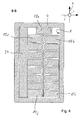
- FIG. 4 shows the end 6 FIG. 3 , as it is received in the substantially rectangular inner contour 8 of the ferrule 4, and wherein a surface pressure in the z-direction and y-direction realized a crimp connection.
- an electrically conductive supplement 24 is introduced between the inner contour 8 of the end sleeve 4 and the stripped bundle conductor 2.
- the supplement 24 advantageously allows an increase in the degree of filling to improve the pressing action and thus the contact.
- the supplement 24 guarantees the electrical contact.
- the variety of variants of the bundle conductors 2 and the end sleeves 4 can be reduced by a corresponding size adaptation by means of the insert 24.
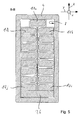
- FIG. 5 shows the end 6 FIG. 3 , as it is received in the substantially rectangular inner contour 8 of the end sleeve 4, wherein a supplement 26 between the inner contour 8 and the end 6 is arranged opposite to the z-direction.
- the supplement 26 can also not one be made of conductive material, since the individual conductors 10i and 10j can already be electrically contacted against the inner contour 8 and in the y direction.
- the supplements 24 and / or 26 can of course also at a different position as in the FIGS. 4 and 5 be shown shown. Of course, several supplements 24 and / or 26 may be provided.
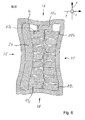
- FIG. 6 shows an embodiment according to FIG. 4 ,
- the external pressure of the ferrule 4 was carried out by means of a pressing tool which has a convex pressing contour.
- FIG. 7 shows a first schematic flow diagram.
- a first step 30 the electrical insulation 20 in the region of the end 6 of the bundle conductor 2 is at least partially removed.
- a second step 32 the end 6 is inserted into the ferrule 4.
- the bundle conductor 2 is press-contacted substantially orthogonally to the side surfaces 12, 14 and / or 13, 15 of the individual conductors 10 in order to produce a crimp connection.
- FIG. 8 shows a second schematic flow diagram.
- the electrically conductive means such as teeth, nubs or cutting, has, which move in the pressing of the ferrule 4 from the outside through the electrical insulation of the individual conductors, introduced.
- the electrical insulation 20 in Section of the end 6 of the bundle conductor 2 at least partially removed by the aforementioned means and by applying pressure substantially orthogonal to the side surfaces 12, 14 and / or 13, 15.
Landscapes
- Engineering & Computer Science (AREA)
- Manufacturing & Machinery (AREA)
- Connections Effected By Soldering, Adhesion, Or Permanent Deformation (AREA)
- Processing Of Terminals (AREA)
Abstract
Description
- Die Erfindung betrifft ein Verfahren zur Herstellung einer elektrischen Verbindung mit einem Bündelleiter nach dem Oberbegriff des Anspruchs 1 und eine Endhülse nach dem Oberbegriff eines nebengeordneten Anspruchs.
- Aus der
DE 10 2004 054 527 B4 ist ein Verfahren zur Herstellung eines mit einer Isolierung versehenen elektrischen Leiters bekannt. Ein flüssiges Zusatzmittel wird auf eine freizuhaltende Stelle auf ein flüssiges Verbindungsmittel aufgetragen. Es bildet sich ein Gemisch aus Verbindungsmittel und Zusatzmittel. Anschließend wird das flüssige Verbindungsmittel mit dem Gemisch einem Verfestigungsprozess unterzogen. Danach wird das Gemisch von der freizuhaltenden Stelle des Leiters mechanisch entfernt. - Bündelleiter, wie beispielsweise Drillleiter zur Herstellung von Transformatorwicklungen sind bekannt. So ist aus der
EP 2 325 949 B1 ein Drillleiter bekannt, bei dem wenigstens zwei Kabel mittels einer Verbindungsbeschichtung, die zumindest zwischen zwei flachen Seiten aufgetragen ist, fest miteinander verbunden sind, um einen Teilsatz zu bilden. - Aufgabe der Erfindung ist es, die Verbindung mit Bündelleitern zu verbessern.
- Die der Erfindung zu Grunde liegende Aufgabe wird durch ein Verfahren nach dem Anspruch 1 und eine Endhülse nach einem nebengeordneten Anspruch gelöst. Vorteilhafte Weiterbildungen sind in den Unteransprüchen angegeben. Für die Erfindung wichtige Merkmale finden sich ferner in der nachfolgenden Beschreibung und in den Zeichnungen, wobei die Merkmale sowohl in Alleinstellung als auch in unterschiedlichen Kombinationen für die Erfindung wichtig sein können, ohne dass hierauf nochmals explizit hingewiesen wird.
- Dadurch, dass ein Bündelleiter im Wesentlichen orthogonal zu Seitenflächen der Einzelleiter druckkontaktiert wird, wird vorteilhaft die Struktur des Bündelleiters ausgenutzt, um eine sicherere elektrische Kontaktierung zwischen allen Einzelleitern und einer Endhülse zu realisieren. Gleichzeitig bleibt die Struktur des Bündelleiters im Wesentlichen bestehen. Im Vergleich zu einer Vorpressung z.B. zur Verrundung, um eine Aufnahme in einer runden Presshülse zu ermöglichen, und anschließenden Herstellung einer Quetschverbindung kann eine Materialverjüngung und Materialermüdung im Bereich der Einzelleiter vermieden werden. Vorteilhaft werden alle Einzelleiter kontaktiert. Vorteilhaft kann hierdurch Zeit bei der Montage eingespart werden und es muss nur in geringem Maße eine Isolation abgetragen werden, weshalb sich sowohl Sauberkeit als auch Arbeitssicherheit verbessern.
- Weitere Merkmale, Anwendungsmöglichkeiten und Vorteile der Erfindung ergeben sich aus der nachfolgenden Beschreibung von Ausführungsbeispielen der Erfindung, die in den Figuren der Zeichnung dargestellt sind. Dabei bilden alle beschriebenen oder dargestellten Merkmale für sich oder in beliebiger Kombination den Gegenstand der Erfindung, unabhängig von ihrer Zusammenfassung in den Patentansprüchen oder deren Rückbeziehung sowie unabhängig von ihrer Formulierung bzw. Darstellung in der Beschreibung bzw. in der Zeichnung. Es werden für funktionsäquivalente Größen und Merkmale in allen Figuren auch bei unterschiedlichen Ausführungsformen die gleichen Bezugszeichen verwendet.
- Nachfolgend werden beispielhafte Ausführungsformen der Erfindung unter Bezugnahme auf die Zeichnung erläutert. In der Zeichnung zeigen
-
Figur 1 zeigt einen Bündelleiter und eine Endhülse in schematischer Form. -
Figur 2 zeigt einen ersten Querschnitt ausFigur 1 . -
Figur 3 zeigt den ersten Querschnitt ausFigur 1 . -
Figur 4 zeigt einen zweiten Querschnitt ausFigur 1 .Figur 5 zeigt einen zweiten Querschnitt ausFigur 1 . -
Figur 6 zeigt einen zweiten Querschnitt ausFigur 1 . -
Figur 7 zeigt ein schematisches Ablaufdiagramm. -
Figur 8 zeigt ein schematisches Ablaufdiagramm. -
Figur 1 zeigt einen Bündelleiter 2 und eine Endhülse 4 in schematischer Form. Der Querschnitt A-A des Bündelleiters 2 wird nachfolgend inFigur 2 näher erläutert. Der Querschnitt B-B durch die Endhülse 4 wird in denFiguren 4 bis 6 näher erläutert. Die Endhülse 2 ist dazu vorgesehen, um eine elektrische Verbindung mit dem Bündelleiter 2 herzustellen. In x-Richtung weist die Endhülse 4 eine weitere, nicht näher erläuterte elektrische Verbindung auf. - Eine elektrische Isolierung im Bereich eines Endes 6 des Bündelleiters 2 wird, wie in
Figur 3 gezeigt, zumindest abschnittsweise entfernt. Das Ende 6 wird in eine Innenkontur 8 der Endhülse 4 eingeführt. Der Bündelleiter 2 wird zur Herstellung einer elektrischen Verbindung zwischen jedem der Einzelleiter und der Endhülse 4 im Wesentlichen orthogonal zu Seitenflächen der Einzelleiter druckkontaktiert. Eine innenliegende Schicht 18 wird auch als Schwert bezeichnet, besteht aus Papier und dient im Bereich der Transformatorwicklung dazu, dass die Einzelleiter 10 nicht ihre Isolation durch ein Aneinanderreiben verletzen. Die Einzelleiter des Bündelleiters 2 und die Endhülse 4 sind elektrisch leitfähig und umfassen bzw. bestehen aus beispielsweise Kupfer.
Die Innenkontur 8 kann elektrisch leitfähige Mittel, wie Zähne, Noppen oder Schneiden, aufweisen, die sich bei der Pressung der Endhülse 4 von außen durch die elektrische Isolierung der Einzelleiter hindurch bewegen und die Seitenflächen der Einzelleiter im Bereich der Außenkontur des Bündelleiters 2 mit der Endhülse 4 elektrisch kontaktieren. Vorteilhaft muss hierbei die Isolierung 20 nicht entfernt werden. Durch die Entfernung im Bereich der Außenkontur entsteht weniger Wärme bei einem Abschleifprozess, da nicht der gesamte Einzelleiter abgeschliffen werden muss. -
Figur 2 zeigt den ersten Querschnitt A-A ausFigur 1 . Der Bündelleiter 2 weist eine Anzahl von im Querschnitt im Wesentlichen rechteckförmigen, gegeneinander elektrisch isolierten Einzelleitern 10 auf. Eine erste Seitenflächen 12 ist in z-Richtung orientiert. Eine zweite Seitenfläche 13 ist in y-Richtung orientiert. Eine dritte Seitenfläche 14 ist entgegen der z-Richtung orientiert. Eine vierte Seitenfläche 15 ist entgegen der y-Richtung orientiert. Alle Seitenflächen 12, 13, 14 und 15 sind von einer elektrischen Isolierung 20 umhüllt, die beispielsweise als isolierender Lack ausgebildet ist. - Die Einzelleiter 10 verlaufen zumindest abschnittsweise entlang des Bündelleiters 2, also in x-Richtung im Wesentlichen parallel zueinander. Die yz-Positionen der Einzelleiter 10 werden im Verlauf des Bündelleiters 2 vertauscht, um beispielsweise bei der Verwendung eines Drillleiters als Teil einer Transformatorwicklung eines Leistungstransformators Verluste zu vermeiden. Selbstverständlich lässt sich die vorliegende Beschreibung nicht nur auf Drillleiter sondern auch auf andere Bündelleiter 2 wie beispielsweise Zwillingsleiter, Drillingsleiter, Doppelkabel oder sonstige Bündelleiter anwenden.
Figur 3 zeigt in schematischer Form den Bündelleiter 2 ausFigur 2 , wobei entlang einer Außenkontur des Bündelleiters 2 die Isolierung 20 entfernt wurde. Mithin liegen die Seitenflächen 12a, 13b bis 13i, 14i und 14j sowie 15j bis 15 s der jeweiligen Einzelleiter 10 frei. Die elektrische Isolierung 20 im Bereich des Endes 6 des Bündelleiters 2 wurde somit zumindest abschnittsweise entfernt. Das Ende 6 kann derart abisoliert in die Endhülse 4 eingeführt werden.
Das Ende 6 des Bündelleiters 2 wird zur Herstellung einer elektrischen Verbindung zwischen jedem der Einzelleiter 10 über die freiliegenden und abisolierten Seitenflächen und der Endhülse 4 im Wesentlichen orthogonal zu den freiliegenden und gegenüberliegenden Seitenflächen 12 und 14 und/oder den freiliegenden und gegenüberliegenden Seitenflächen 13 und 15 der jeweiligen Einzelleiter 10 druckkontaktiert. Mithin findet eine Druckkontaktierung in z-Richtung und/oder in y-Richtung statt. - Bei der Entfernung der Isolierung 20 im Bereich der Außenkontur des Bündelleiters 2 bleibt die elektrische Isolierung innerhalb des Bündelleiters 2 erhalten. Damit wird die mechanische Struktur des Bündelleiters 2 erhalten. Vorteilhaft kann so eine schnelle und sichere elektrische Kontaktierung aller Einzelleiter 10 mit der Endhülse 4 durchgeführt werden. Die Entfernung der Isolierung im Bereich der Außenkontur der Bündelleiters 2 kann beispielsweise durch ein Abschleifen, Abbrennen oder aber Sandstrahlen geschehen. Durch die Entfernung lediglich eines Teils der Isolierung 20 bezüglich eines einzelnen Einzelleiters 10 wird vorteilhaft erreicht, dass eine saubere und sichere Kontaktierung stattfindet.
- Selbstverständlich kann jeder der Einzelleiter 10 auch komplett von der Isolierung 20 befreit werden. Jedoch kann auch hier die rechteckförmige Struktur der Einzelleiter 10 dazu genutzt werden, um vorteilhaft eine Pressung und flächige Druckkontaktierung mit den nach außen gewandten Seitenflächen der Einzelleiter 10 zu erreichen.
- Bei der Abtragung der elektrischen Isolierung 20 im Bereich der Außenkontur des Bündelleiters 2 durch ein Strahlen mittels eines Strahlguts kann vorteilhaft eine nicht gezeigte Strahlvorrichtung verwendet werden, in die das Ende 6 vor der Montage mit der Endhülse 4 zur äußerlichen Entfernung der Isolierung 20 hineingehalten wird.
- Nach dem Entfernen der Isolierung 20 im Bereich der Außenkontur wird mittels einer Außenpressung der Endhülse 4 eine Quetschverbindung hergestellt wird. Selbstverständlich kann das Ende 6 auch durch eine anders ausgestaltete Klemmverbindung in y-Richtung und/oder in z-Richtung mit Druck beaufschlagt werden, um sowohl eine mechanische als auch eine elektrische Verbindung der Einzelleiter 10 mit der Endhülse 4 zu realisieren. So kann beispielsweise eine Klemmung nach der Art einer Fahrstuhlklemme erfolgen.
-
Figur 4 zeigt das Ende 6 ausFigur 3 , wie es in der im Wesentlichen rechteckigen Innenkontur 8 der Endhülse 4 aufgenommen ist, und wobei eine flächige Pressung in z-Richtung und y-Richtung eine Quetschverbindung verwirklicht. Des Weiteren ist eine elektrisch leitfähige Beilage 24 zwischen der Innenkontur 8 der Endhülse 4 und dem abisolierten Bündelleiter 2 eingebracht. Die Beilage 24 ermöglicht vorteilhaft eine Erhöhung des Füllungsgrades zur Verbesserung der Presswirkung und damit der Kontaktierung. Darüber hinaus garantiert die Beilage 24 die elektrische Kontaktierung. Vorteilhaft kann durch unterschiedliche Größen der Beilage 24 die Variantenvielfalt der Bündelleiter 2 und der Endhülsen 4 durch eine entsprechende Größenanpassung mittels der Beilage 24 reduziert werden. -
Figur 5 zeigt das Ende 6 ausFigur 3 , wie es in der im Wesentlichen rechteckigen Innenkontur 8 der Endhülse 4 aufgenommen ist, wobei eine Beilage 26 zwischen der Innenkontur 8 und dem Ende 6 entgegen der z-Richtung angeordnet ist. Die Beilage 26 kann auch aus einem nicht leitenden Material gefertigt sein, da die Einzelleiter 10i und 10j bereits entgegen und in der y-Richtung mit der Innenkontur 8 elektrisch kontaktiert werden können. - Die Beilagen 24 und/oder 26 können selbstverständlich auch an einer anderen Position wie in den
Figuren 4 und5 gezeigt angeordnet sein. Selbstverständlich können auch mehrere Beilagen 24 und/oder 26 vorgesehen werden. -
Figur 6 zeigt eine Ausführungsform nachFigur 4 . Die Außenpressung der Endhülse 4 wurde mittels eines Presswerkzeugs ausgeführt, das eine konvexe Presskontur aufweist. Mithin hat die Endhülse 4 im Querschnitt nachFigur 6 nach der Pressung konkave Seitenkonturen 28, wodurch die Innenkontur 8 sich entsprechend ausbildet und eine Kontaktierung aller Einzelleiter 10 mit der Innenkontur 8 der Endhülse 4 verbessert wird. -
Figur 7 zeigt ein erstes schematisches Ablaufdiagramm. In einem ersten Schritt 30 wird die elektrische Isolierung 20 im Bereich des Endes 6 des Bündelleiters 2 zumindest abschnittsweise entfernt. In einem zweiten Schritt 32 wird das Ende 6 in die Endhülse 4 eingeführt. In einem dritten Schritt 34 wird der Bündelleiter 2 im Wesentlichen orthogonal zu den Seitenflächen 12, 14 und/oder 13, 15 der Einzelleiter 10 druckkontaktiert, um eine Quetschverbindung herzustellen. -
Figur 8 zeigt ein zweites schematisches Ablaufdiagramm. In einem ersten Schritt 40 wird das Ende 6 in die Innenkontur 8, die elektrisch leitfähige Mittel, wie Zähne, Noppen oder Schneiden, aufweist, die sich bei der Pressung der Endhülse 4 von außen durch die elektrische Isolierung der Einzelleiter hindurch bewegen, eingebracht. In einem zweiten Schritt 42 wird die elektrische Isolierung 20 im Bereich des Endes 6 des Bündelleiters 2 zumindest abschnittsweise durch die vorgenannten Mittel und durch eine Druckbeaufschlagung im Wesentlichen orthogonal zu den Seitenflächen 12, 14 und/oder 13, 15 entfernt.
Claims (14)
- Ein Verfahren zur Herstellung einer elektrischen Verbindung mit einem Bündelleiter (2), insbesondere mit einem Drillleiter, der eine Anzahl von im Querschnitt im Wesentlichen rechteckförmigen, gegeneinander elektrisch isolierten Einzelleitern (10) aufweist, wobei Seitenflächen (12, 14; 13, 15) der Einzelleiter (10) zumindest abschnittsweise entlang des Bündelleiters (2) im Wesentlichen parallel zueinander verlaufen, dadurch gekennzeichnet, dass die elektrische Isolierung (20) im Bereich eines Endes (6) des Bündelleiters (2) zumindest abschnittsweise entfernt wird, dass das Ende (6) in eine Endhülse (4) eingeführt wird, und dass der Bündelleiter (2) im Wesentlichen orthogonal zu den Seitenflächen (12, 14; 13, 15) der Einzelleiter (10) druckkontaktiert wird.
- Das Verfahren nach Anspruch 1, wobei die elektrische Isolierung (20) im Bereich der Außenkontur des Bündelleiters (2) entfernt wird, und wobei die elektrische Isolierung (20) innerhalb des Bündelleiters (2) im Bereich des Endes (6) im Wesentlichen erhalten bleibt.
- Das Verfahren nach Anspruch 2, wobei die elektrische Isolierung (20) im Bereich der Außenkontur der Bündelleiters (2) durch ein Strahlen mittels eines Strahlguts abgetragen wird.
- Das Verfahren nach einem der vorstehenden Ansprüche, wobei mittels einer Außenpressung der Endhülse (4) eine Quetschverbindung hergestellt wird.
- Das Verfahren nach einem der vorstehenden Ansprüche, wobei die Außenpressung der Endhülse (4) mittels eines Presswerkzeugs ausgeführt wird, das eine konvexe Presskontur aufweist, und wobei die Endhülse (4) nach der Pressung eine konkave Seitenkontur (28) aufweist.
- Das Verfahren nach einem der vorstehenden Ansprüche, wobei die Endhülse (4) eine im Wesentlichen rechteckige Innenkontur (8) zur Aufnahme des Endes (6) des Bündelleiters (2) aufweist.
- Das Verfahren nach einem der vorstehenden Ansprüche, wobei vor der Pressung eine elektrisch leitfähige Beilage (24) zwischen der Innenkontur (8) der Endhülse (4) und dem Ende (6) des Bündelleiters (2) eingebracht wird.
- Das Verfahren nach einem der vorstehenden Ansprüche, wobei vor der Pressung eine elektrisch isolierende Beilage (26) zwischen der Innenkontur (8) der Endhülse (8) und dem Ende (6) des Bündelleiters (2) eingebracht wird.
- Das Verfahren nach Anspruch 7 oder 8, wobei Beilage (24; 26) elektrisch leitfähige Mittel aufweist, die sich bei der Pressung durch die elektrische Isolierung (20) hindurch bewegen und die Seitenflächen (12, 14; 13, 15) der Einzelleiter (10) im Bereich der Außenkontur des Bündelleiters (2) mit der Endhülse (4) elektrisch kontaktieren.
- Das Verfahren nach einem der vorstehenden Ansprüche, wobei die Innenkontur (8) der Endhülse (4) elektrisch leitfähige Mittel aufweist, die sich bei der Pressung durch die elektrische Isolierung (20) hindurch bewegen und die Seitenflächen (12, 14; 13, 15) der Einzelleiter (10) im Bereich der Außenkontur des Bündelleiters (2) mit der Endhülse (4) elektrisch kontaktieren.
- Eine Endhülse (4) zur Herstellung einer elektrischen Verbindung mit einem Bündelleiter (2), insbesondere mit einem Drillleiter, der eine Anzahl von im Querschnitt im Wesentlichen rechteckförmigen, gegeneinander elektrisch isolierten Einzelleitern (10) aufweist, wobei Seitenflächen (12, 14; 13, 15) der Einzelleiter (10) zumindest abschnittsweise entlang des Bündelleiters (2) im Wesentlichen parallel zueinander verlaufen, dadurch gekennzeichnet, dass die elektrische Isolierung (20) im Bereich eines Endes (6) des Bündelleiters (2) zumindest abschnittsweise entfernbar ist, dass das Ende (6) in die Endhülse (4) einführbar ist, und dass der Bündelleiter (2) im Wesentlichen orthogonal zu den Seitenflächen (12, 14; 13, 15) der Einzelleiter (10) druckkontaktierbar ist.
- Die Endhülse (4) nach dem vorstehenden Anspruch, die nach dem Verfahren nach einem der Ansprüche 1 bis 9 hergestellt ist.
- Ein Leistungstransformator umfassend die Endhülse (4) nach Anspruch 11 oder 12 und den mit der Endhülse (4) elektrisch verbundenen Bündelleiter (2).
- Der Leistungstransformator nach Anspruch 12, wobei der Bündelleiter (2) ein Drillleiter ist, und wobei eine Transformatorwicklung den Drillleiter umfasst.
Applications Claiming Priority (1)
| Application Number | Priority Date | Filing Date | Title |
|---|---|---|---|
| DE102014219809.7A DE102014219809A1 (de) | 2014-09-30 | 2014-09-30 | Verfahren zur Herstellung einer elektrischen Verbindung mit einem Bündelleiter und Endhülse |
Publications (2)
| Publication Number | Publication Date |
|---|---|
| EP3002827A1 true EP3002827A1 (de) | 2016-04-06 |
| EP3002827B1 EP3002827B1 (de) | 2020-02-19 |
Family
ID=54185851
Family Applications (1)
| Application Number | Title | Priority Date | Filing Date |
|---|---|---|---|
| EP15185709.1A Active EP3002827B1 (de) | 2014-09-30 | 2015-09-17 | Verfahren zur herstellung einer elektrischen verbindung einer endhülse mit einem drillleiter und anordnung |
Country Status (3)
| Country | Link |
|---|---|
| EP (1) | EP3002827B1 (de) |
| DE (1) | DE102014219809A1 (de) |
| ES (1) | ES2776206T3 (de) |
Citations (7)
| Publication number | Priority date | Publication date | Assignee | Title |
|---|---|---|---|---|
| DE2723029A1 (de) * | 1977-05-21 | 1978-11-30 | Bosch Gmbh Robert | Elektrische verbindung lackierter und unlackierter draehte und verfahren zur herstellung der verbindung |
| DE69108110T2 (de) * | 1990-06-05 | 1995-08-24 | Eurocopter France | Verfahren zum Verbinden eines elektrischen Leiters mit einem Stift eines Verbinders und die durch Ausführung dieses Verfahren erhaltene elektrische Verbindung. |
| DE102004054527B4 (de) | 2004-11-05 | 2006-10-12 | Siemens Ag | Verfahren zur Herstellung einer von einer Isolierung freizuhaltenden Stelle eines isolierten Leiters und Trennmittel |
| CN101604572A (zh) * | 2009-04-14 | 2009-12-16 | 焦海波 | 干式变压器或电抗器的绕组导线与引线电缆的连接方法 |
| EP2192601A1 (de) * | 2007-09-18 | 2010-06-02 | AutoNetworks Technologies, Ltd. | Kabelbaum, verfahren zu seiner herstellung und verbindungsverfahren für einen isolierten elektrischen draht |
| EP2325949A1 (de) | 2009-11-19 | 2011-05-25 | Hager Electro GmbH & Co. KG | Anschlussvorrichtung für einen elektronischen Stromzähler |
| DE112011103639T5 (de) * | 2010-11-01 | 2013-08-08 | Yazaki Corporation | Elektrodraht-Halteaufbau und Elektrodraht-Halteverfahren |
Family Cites Families (1)
| Publication number | Priority date | Publication date | Assignee | Title |
|---|---|---|---|---|
| JP4631951B2 (ja) * | 2008-09-19 | 2011-02-16 | パナソニック株式会社 | 巻線コイルと銅線との洗濯機用電気接続手段 |
-
2014
- 2014-09-30 DE DE102014219809.7A patent/DE102014219809A1/de not_active Withdrawn
-
2015
- 2015-09-17 ES ES15185709T patent/ES2776206T3/es active Active
- 2015-09-17 EP EP15185709.1A patent/EP3002827B1/de active Active
Patent Citations (7)
| Publication number | Priority date | Publication date | Assignee | Title |
|---|---|---|---|---|
| DE2723029A1 (de) * | 1977-05-21 | 1978-11-30 | Bosch Gmbh Robert | Elektrische verbindung lackierter und unlackierter draehte und verfahren zur herstellung der verbindung |
| DE69108110T2 (de) * | 1990-06-05 | 1995-08-24 | Eurocopter France | Verfahren zum Verbinden eines elektrischen Leiters mit einem Stift eines Verbinders und die durch Ausführung dieses Verfahren erhaltene elektrische Verbindung. |
| DE102004054527B4 (de) | 2004-11-05 | 2006-10-12 | Siemens Ag | Verfahren zur Herstellung einer von einer Isolierung freizuhaltenden Stelle eines isolierten Leiters und Trennmittel |
| EP2192601A1 (de) * | 2007-09-18 | 2010-06-02 | AutoNetworks Technologies, Ltd. | Kabelbaum, verfahren zu seiner herstellung und verbindungsverfahren für einen isolierten elektrischen draht |
| CN101604572A (zh) * | 2009-04-14 | 2009-12-16 | 焦海波 | 干式变压器或电抗器的绕组导线与引线电缆的连接方法 |
| EP2325949A1 (de) | 2009-11-19 | 2011-05-25 | Hager Electro GmbH & Co. KG | Anschlussvorrichtung für einen elektronischen Stromzähler |
| DE112011103639T5 (de) * | 2010-11-01 | 2013-08-08 | Yazaki Corporation | Elektrodraht-Halteaufbau und Elektrodraht-Halteverfahren |
Also Published As
| Publication number | Publication date |
|---|---|
| DE102014219809A1 (de) | 2016-03-31 |
| ES2776206T3 (es) | 2020-07-29 |
| EP3002827B1 (de) | 2020-02-19 |
Similar Documents
| Publication | Publication Date | Title |
|---|---|---|
| DE102008058845B4 (de) | Verbindungsaufbau und Verbindungsverfahren für einen Kupferdraht und einen Aluminiumdraht | |
| WO2009100812A2 (de) | Elektrische anschlusseinrichtung | |
| DE1057193B (de) | Elektrischer Presshuelsenverbinder | |
| DE112010000873B4 (de) | Verfahren zum Verbinden elektrischer Leitungen | |
| DE2545011A1 (de) | Anwuergverbindung und verfahren zu ihrer herstellung | |
| DE102012206145A1 (de) | Verfahren zum Fertigen einer Drahtabgangsanordnung für eine elektrische Maschine sowie entsprechende Drahtabgangsanordnung | |
| DE2024364C3 (de) | Elektrische Verbindungsklemme für isolierten Aluminiumdraht | |
| EP3609023A1 (de) | Verfahren und vorrichtung zur herstellung einer elektrischen verbindung und elektrische leitung | |
| DE10026294A1 (de) | Kabelsteckverbinder | |
| DE102013021278B3 (de) | Verfahren zum elektrisch leitenden Verbinden einer Leitung mit einem Kontaktelement | |
| EP3002827B1 (de) | Verfahren zur herstellung einer elektrischen verbindung einer endhülse mit einem drillleiter und anordnung | |
| EP4595171B1 (de) | Verfahren zum verschweissen von leitungen zu einer y- oder x-verbindung mittels ultraschall | |
| DE10200282A1 (de) | Selbsttätig abisolierendes Anschlusselement mit einem konvergierenden Schlitz | |
| DE1515399A1 (de) | Gewellte elektrische Verbindungsklemme | |
| DE19856568B4 (de) | Verbindungselement für eine Verzweigung von elektrischen Kabeln | |
| DE3220630C2 (de) | ||
| DE3220657C2 (de) | ||
| EP1187256A2 (de) | Elektrisches Verbindungselement | |
| DE2937858A1 (de) | Anschlussklemme fuer messgeraetekabel | |
| DE102023114098A1 (de) | Kabel mit einem Steckabschnitt und Verfahren zu dessen Herstellung | |
| WO2018046576A1 (de) | Elektrisches verbindungselement und querbrückeneinrichtung für elektrische klemmen | |
| DE102023119381A1 (de) | Crimpvorrichtung, Verfahren zum Herstellen einer Crimpverbindung und Verbund aus einem elektrischen Leiter und elektrischem Verbinder | |
| DE102023200734A1 (de) | Verfahren zum Herstellen eines elektrisch leitfähigen Verbindungselements für ein elektrisches oder elektronisches Bauteil und Verbindungselement | |
| DE102024204642A1 (de) | Verfahren zur Herstellung eines Stators, Elektromaschine und Kraftfahrzeug | |
| DE2012594C (de) | Vorrichtung zur Schnellverbindung zweier isolierter elektrischer Leitungsdrähte |
Legal Events
| Date | Code | Title | Description |
|---|---|---|---|
| PUAI | Public reference made under article 153(3) epc to a published international application that has entered the european phase |
Free format text: ORIGINAL CODE: 0009012 |
|
| AK | Designated contracting states |
Kind code of ref document: A1 Designated state(s): AL AT BE BG CH CY CZ DE DK EE ES FI FR GB GR HR HU IE IS IT LI LT LU LV MC MK MT NL NO PL PT RO RS SE SI SK SM TR |
|
| AX | Request for extension of the european patent |
Extension state: BA ME |
|
| 17P | Request for examination filed |
Effective date: 20160916 |
|
| RBV | Designated contracting states (corrected) |
Designated state(s): AL AT BE BG CH CY CZ DE DK EE ES FI FR GB GR HR HU IE IS IT LI LT LU LV MC MK MT NL NO PL PT RO RS SE SI SK SM TR |
|
| STAA | Information on the status of an ep patent application or granted ep patent |
Free format text: STATUS: EXAMINATION IS IN PROGRESS |
|
| 17Q | First examination report despatched |
Effective date: 20180327 |
|
| REG | Reference to a national code |
Ref country code: DE Ref legal event code: R079 Ref document number: 502015011758 Country of ref document: DE Free format text: PREVIOUS MAIN CLASS: H01R0004200000 Ipc: H01F0027280000 |
|
| GRAP | Despatch of communication of intention to grant a patent |
Free format text: ORIGINAL CODE: EPIDOSNIGR1 |
|
| STAA | Information on the status of an ep patent application or granted ep patent |
Free format text: STATUS: GRANT OF PATENT IS INTENDED |
|
| RIC1 | Information provided on ipc code assigned before grant |
Ipc: H01R 4/20 20060101ALI20190819BHEP Ipc: H01F 27/28 20060101AFI20190819BHEP Ipc: H01R 43/05 20060101ALI20190819BHEP |
|
| INTG | Intention to grant announced |
Effective date: 20190911 |
|
| GRAS | Grant fee paid |
Free format text: ORIGINAL CODE: EPIDOSNIGR3 |
|
| GRAJ | Information related to disapproval of communication of intention to grant by the applicant or resumption of examination proceedings by the epo deleted |
Free format text: ORIGINAL CODE: EPIDOSDIGR1 |
|
| GRAL | Information related to payment of fee for publishing/printing deleted |
Free format text: ORIGINAL CODE: EPIDOSDIGR3 |
|
| STAA | Information on the status of an ep patent application or granted ep patent |
Free format text: STATUS: EXAMINATION IS IN PROGRESS |
|
| GRAR | Information related to intention to grant a patent recorded |
Free format text: ORIGINAL CODE: EPIDOSNIGR71 |
|
| STAA | Information on the status of an ep patent application or granted ep patent |
Free format text: STATUS: GRANT OF PATENT IS INTENDED |
|
| GRAA | (expected) grant |
Free format text: ORIGINAL CODE: 0009210 |
|
| STAA | Information on the status of an ep patent application or granted ep patent |
Free format text: STATUS: THE PATENT HAS BEEN GRANTED |
|
| INTC | Intention to grant announced (deleted) | ||
| AK | Designated contracting states |
Kind code of ref document: B1 Designated state(s): AL AT BE BG CH CY CZ DE DK EE ES FI FR GB GR HR HU IE IS IT LI LT LU LV MC MK MT NL NO PL PT RO RS SE SI SK SM TR |
|
| INTG | Intention to grant announced |
Effective date: 20200110 |
|
| REG | Reference to a national code |
Ref country code: CH Ref legal event code: EP |
|
| REG | Reference to a national code |
Ref country code: DE Ref legal event code: R096 Ref document number: 502015011758 Country of ref document: DE |
|
| REG | Reference to a national code |
Ref country code: AT Ref legal event code: REF Ref document number: 1235899 Country of ref document: AT Kind code of ref document: T Effective date: 20200315 |
|
| REG | Reference to a national code |
Ref country code: IE Ref legal event code: FG4D Free format text: LANGUAGE OF EP DOCUMENT: GERMAN |
|
| REG | Reference to a national code |
Ref country code: NL Ref legal event code: MP Effective date: 20200219 |
|
| REG | Reference to a national code |
Ref country code: ES Ref legal event code: FG2A Ref document number: 2776206 Country of ref document: ES Kind code of ref document: T3 Effective date: 20200729 |
|
| PG25 | Lapsed in a contracting state [announced via postgrant information from national office to epo] |
Ref country code: FI Free format text: LAPSE BECAUSE OF FAILURE TO SUBMIT A TRANSLATION OF THE DESCRIPTION OR TO PAY THE FEE WITHIN THE PRESCRIBED TIME-LIMIT Effective date: 20200219 Ref country code: NO Free format text: LAPSE BECAUSE OF FAILURE TO SUBMIT A TRANSLATION OF THE DESCRIPTION OR TO PAY THE FEE WITHIN THE PRESCRIBED TIME-LIMIT Effective date: 20200519 Ref country code: RS Free format text: LAPSE BECAUSE OF FAILURE TO SUBMIT A TRANSLATION OF THE DESCRIPTION OR TO PAY THE FEE WITHIN THE PRESCRIBED TIME-LIMIT Effective date: 20200219 |
|
| REG | Reference to a national code |
Ref country code: DE Ref legal event code: R082 Ref document number: 502015011758 Country of ref document: DE Representative=s name: RUEGER ABEL PATENTANWAELTE PARTGMBB, DE Ref country code: DE Ref legal event code: R081 Ref document number: 502015011758 Country of ref document: DE Owner name: GENERAL ELECTRIC TECHNOLOGY GMBH, CH Free format text: FORMER OWNER: ALSTOM TECHNOLOGY LTD, BADEN, CH |
|
| RAP2 | Party data changed (patent owner data changed or rights of a patent transferred) |
Owner name: GENERAL ELECTRIC TECHNOLOGY GMBH |
|
| REG | Reference to a national code |
Ref country code: LT Ref legal event code: MG4D |
|
| PG25 | Lapsed in a contracting state [announced via postgrant information from national office to epo] |
Ref country code: BG Free format text: LAPSE BECAUSE OF FAILURE TO SUBMIT A TRANSLATION OF THE DESCRIPTION OR TO PAY THE FEE WITHIN THE PRESCRIBED TIME-LIMIT Effective date: 20200519 Ref country code: GR Free format text: LAPSE BECAUSE OF FAILURE TO SUBMIT A TRANSLATION OF THE DESCRIPTION OR TO PAY THE FEE WITHIN THE PRESCRIBED TIME-LIMIT Effective date: 20200520 Ref country code: IS Free format text: LAPSE BECAUSE OF FAILURE TO SUBMIT A TRANSLATION OF THE DESCRIPTION OR TO PAY THE FEE WITHIN THE PRESCRIBED TIME-LIMIT Effective date: 20200619 Ref country code: SE Free format text: LAPSE BECAUSE OF FAILURE TO SUBMIT A TRANSLATION OF THE DESCRIPTION OR TO PAY THE FEE WITHIN THE PRESCRIBED TIME-LIMIT Effective date: 20200219 Ref country code: LV Free format text: LAPSE BECAUSE OF FAILURE TO SUBMIT A TRANSLATION OF THE DESCRIPTION OR TO PAY THE FEE WITHIN THE PRESCRIBED TIME-LIMIT Effective date: 20200219 Ref country code: HR Free format text: LAPSE BECAUSE OF FAILURE TO SUBMIT A TRANSLATION OF THE DESCRIPTION OR TO PAY THE FEE WITHIN THE PRESCRIBED TIME-LIMIT Effective date: 20200219 |
|
| PG25 | Lapsed in a contracting state [announced via postgrant information from national office to epo] |
Ref country code: NL Free format text: LAPSE BECAUSE OF FAILURE TO SUBMIT A TRANSLATION OF THE DESCRIPTION OR TO PAY THE FEE WITHIN THE PRESCRIBED TIME-LIMIT Effective date: 20200219 |
|
| REG | Reference to a national code |
Ref country code: GB Ref legal event code: 732E Free format text: REGISTERED BETWEEN 20200917 AND 20200923 |
|
| PG25 | Lapsed in a contracting state [announced via postgrant information from national office to epo] |
Ref country code: SK Free format text: LAPSE BECAUSE OF FAILURE TO SUBMIT A TRANSLATION OF THE DESCRIPTION OR TO PAY THE FEE WITHIN THE PRESCRIBED TIME-LIMIT Effective date: 20200219 Ref country code: PT Free format text: LAPSE BECAUSE OF FAILURE TO SUBMIT A TRANSLATION OF THE DESCRIPTION OR TO PAY THE FEE WITHIN THE PRESCRIBED TIME-LIMIT Effective date: 20200712 Ref country code: DK Free format text: LAPSE BECAUSE OF FAILURE TO SUBMIT A TRANSLATION OF THE DESCRIPTION OR TO PAY THE FEE WITHIN THE PRESCRIBED TIME-LIMIT Effective date: 20200219 Ref country code: EE Free format text: LAPSE BECAUSE OF FAILURE TO SUBMIT A TRANSLATION OF THE DESCRIPTION OR TO PAY THE FEE WITHIN THE PRESCRIBED TIME-LIMIT Effective date: 20200219 Ref country code: SM Free format text: LAPSE BECAUSE OF FAILURE TO SUBMIT A TRANSLATION OF THE DESCRIPTION OR TO PAY THE FEE WITHIN THE PRESCRIBED TIME-LIMIT Effective date: 20200219 Ref country code: RO Free format text: LAPSE BECAUSE OF FAILURE TO SUBMIT A TRANSLATION OF THE DESCRIPTION OR TO PAY THE FEE WITHIN THE PRESCRIBED TIME-LIMIT Effective date: 20200219 Ref country code: CZ Free format text: LAPSE BECAUSE OF FAILURE TO SUBMIT A TRANSLATION OF THE DESCRIPTION OR TO PAY THE FEE WITHIN THE PRESCRIBED TIME-LIMIT Effective date: 20200219 Ref country code: LT Free format text: LAPSE BECAUSE OF FAILURE TO SUBMIT A TRANSLATION OF THE DESCRIPTION OR TO PAY THE FEE WITHIN THE PRESCRIBED TIME-LIMIT Effective date: 20200219 |
|
| REG | Reference to a national code |
Ref country code: DE Ref legal event code: R097 Ref document number: 502015011758 Country of ref document: DE |
|
| PLBE | No opposition filed within time limit |
Free format text: ORIGINAL CODE: 0009261 |
|
| STAA | Information on the status of an ep patent application or granted ep patent |
Free format text: STATUS: NO OPPOSITION FILED WITHIN TIME LIMIT |
|
| 26N | No opposition filed |
Effective date: 20201120 |
|
| PG25 | Lapsed in a contracting state [announced via postgrant information from national office to epo] |
Ref country code: PL Free format text: LAPSE BECAUSE OF FAILURE TO SUBMIT A TRANSLATION OF THE DESCRIPTION OR TO PAY THE FEE WITHIN THE PRESCRIBED TIME-LIMIT Effective date: 20200219 Ref country code: SI Free format text: LAPSE BECAUSE OF FAILURE TO SUBMIT A TRANSLATION OF THE DESCRIPTION OR TO PAY THE FEE WITHIN THE PRESCRIBED TIME-LIMIT Effective date: 20200219 |
|
| PG25 | Lapsed in a contracting state [announced via postgrant information from national office to epo] |
Ref country code: MC Free format text: LAPSE BECAUSE OF FAILURE TO SUBMIT A TRANSLATION OF THE DESCRIPTION OR TO PAY THE FEE WITHIN THE PRESCRIBED TIME-LIMIT Effective date: 20200219 |
|
| REG | Reference to a national code |
Ref country code: CH Ref legal event code: PL |
|
| REG | Reference to a national code |
Ref country code: BE Ref legal event code: MM Effective date: 20200930 |
|
| PG25 | Lapsed in a contracting state [announced via postgrant information from national office to epo] |
Ref country code: LU Free format text: LAPSE BECAUSE OF NON-PAYMENT OF DUE FEES Effective date: 20200917 |
|
| PG25 | Lapsed in a contracting state [announced via postgrant information from national office to epo] |
Ref country code: LI Free format text: LAPSE BECAUSE OF NON-PAYMENT OF DUE FEES Effective date: 20200930 Ref country code: IE Free format text: LAPSE BECAUSE OF NON-PAYMENT OF DUE FEES Effective date: 20200917 Ref country code: BE Free format text: LAPSE BECAUSE OF NON-PAYMENT OF DUE FEES Effective date: 20200930 Ref country code: CH Free format text: LAPSE BECAUSE OF NON-PAYMENT OF DUE FEES Effective date: 20200930 |
|
| REG | Reference to a national code |
Ref country code: AT Ref legal event code: MM01 Ref document number: 1235899 Country of ref document: AT Kind code of ref document: T Effective date: 20200917 |
|
| PG25 | Lapsed in a contracting state [announced via postgrant information from national office to epo] |
Ref country code: AT Free format text: LAPSE BECAUSE OF NON-PAYMENT OF DUE FEES Effective date: 20200917 |
|
| PG25 | Lapsed in a contracting state [announced via postgrant information from national office to epo] |
Ref country code: TR Free format text: LAPSE BECAUSE OF FAILURE TO SUBMIT A TRANSLATION OF THE DESCRIPTION OR TO PAY THE FEE WITHIN THE PRESCRIBED TIME-LIMIT Effective date: 20200219 Ref country code: MT Free format text: LAPSE BECAUSE OF FAILURE TO SUBMIT A TRANSLATION OF THE DESCRIPTION OR TO PAY THE FEE WITHIN THE PRESCRIBED TIME-LIMIT Effective date: 20200219 Ref country code: CY Free format text: LAPSE BECAUSE OF FAILURE TO SUBMIT A TRANSLATION OF THE DESCRIPTION OR TO PAY THE FEE WITHIN THE PRESCRIBED TIME-LIMIT Effective date: 20200219 |
|
| PG25 | Lapsed in a contracting state [announced via postgrant information from national office to epo] |
Ref country code: MK Free format text: LAPSE BECAUSE OF FAILURE TO SUBMIT A TRANSLATION OF THE DESCRIPTION OR TO PAY THE FEE WITHIN THE PRESCRIBED TIME-LIMIT Effective date: 20200219 Ref country code: AL Free format text: LAPSE BECAUSE OF FAILURE TO SUBMIT A TRANSLATION OF THE DESCRIPTION OR TO PAY THE FEE WITHIN THE PRESCRIBED TIME-LIMIT Effective date: 20200219 |
|
| PGFP | Annual fee paid to national office [announced via postgrant information from national office to epo] |
Ref country code: IT Payment date: 20220825 Year of fee payment: 8 Ref country code: GB Payment date: 20220819 Year of fee payment: 8 Ref country code: DE Payment date: 20220616 Year of fee payment: 8 |
|
| PGFP | Annual fee paid to national office [announced via postgrant information from national office to epo] |
Ref country code: FR Payment date: 20220819 Year of fee payment: 8 |
|
| PGFP | Annual fee paid to national office [announced via postgrant information from national office to epo] |
Ref country code: ES Payment date: 20221003 Year of fee payment: 8 |
|
| P01 | Opt-out of the competence of the unified patent court (upc) registered |
Effective date: 20230522 |
|
| REG | Reference to a national code |
Ref country code: DE Ref legal event code: R119 Ref document number: 502015011758 Country of ref document: DE |
|
| GBPC | Gb: european patent ceased through non-payment of renewal fee |
Effective date: 20230917 |
|
| PG25 | Lapsed in a contracting state [announced via postgrant information from national office to epo] |
Ref country code: GB Free format text: LAPSE BECAUSE OF NON-PAYMENT OF DUE FEES Effective date: 20230917 |
|
| PG25 | Lapsed in a contracting state [announced via postgrant information from national office to epo] |
Ref country code: GB Free format text: LAPSE BECAUSE OF NON-PAYMENT OF DUE FEES Effective date: 20230917 Ref country code: FR Free format text: LAPSE BECAUSE OF NON-PAYMENT OF DUE FEES Effective date: 20230930 Ref country code: DE Free format text: LAPSE BECAUSE OF NON-PAYMENT OF DUE FEES Effective date: 20240403 |
|
| REG | Reference to a national code |
Ref country code: ES Ref legal event code: FD2A Effective date: 20241029 |
|
| PG25 | Lapsed in a contracting state [announced via postgrant information from national office to epo] |
Ref country code: IT Free format text: LAPSE BECAUSE OF NON-PAYMENT OF DUE FEES Effective date: 20230917 |
|
| PG25 | Lapsed in a contracting state [announced via postgrant information from national office to epo] |
Ref country code: IT Free format text: LAPSE BECAUSE OF NON-PAYMENT OF DUE FEES Effective date: 20230917 |
|
| PG25 | Lapsed in a contracting state [announced via postgrant information from national office to epo] |
Ref country code: ES Free format text: LAPSE BECAUSE OF NON-PAYMENT OF DUE FEES Effective date: 20230918 |
|
| PG25 | Lapsed in a contracting state [announced via postgrant information from national office to epo] |
Ref country code: ES Free format text: LAPSE BECAUSE OF NON-PAYMENT OF DUE FEES Effective date: 20230918 |