EP3002630A1 - Mobiler dokumentenleser - Google Patents
Mobiler dokumentenleser Download PDFInfo
- Publication number
- EP3002630A1 EP3002630A1 EP15185701.8A EP15185701A EP3002630A1 EP 3002630 A1 EP3002630 A1 EP 3002630A1 EP 15185701 A EP15185701 A EP 15185701A EP 3002630 A1 EP3002630 A1 EP 3002630A1
- Authority
- EP
- European Patent Office
- Prior art keywords
- document
- camera
- light
- mobile
- reader according
- Prior art date
- Legal status (The legal status is an assumption and is not a legal conclusion. Google has not performed a legal analysis and makes no representation as to the accuracy of the status listed.)
- Granted
Links
Images


Classifications
-
- G—PHYSICS
- G03—PHOTOGRAPHY; CINEMATOGRAPHY; ANALOGOUS TECHNIQUES USING WAVES OTHER THAN OPTICAL WAVES; ELECTROGRAPHY; HOLOGRAPHY
- G03B—APPARATUS OR ARRANGEMENTS FOR TAKING PHOTOGRAPHS OR FOR PROJECTING OR VIEWING THEM; APPARATUS OR ARRANGEMENTS EMPLOYING ANALOGOUS TECHNIQUES USING WAVES OTHER THAN OPTICAL WAVES; ACCESSORIES THEREFOR
- G03B15/00—Special procedures for taking photographs; Apparatus therefor
- G03B15/02—Illuminating scene
- G03B15/06—Special arrangements of screening, diffusing, or reflecting devices, e.g. in studio
-
- G—PHYSICS
- G03—PHOTOGRAPHY; CINEMATOGRAPHY; ANALOGOUS TECHNIQUES USING WAVES OTHER THAN OPTICAL WAVES; ELECTROGRAPHY; HOLOGRAPHY
- G03B—APPARATUS OR ARRANGEMENTS FOR TAKING PHOTOGRAPHS OR FOR PROJECTING OR VIEWING THEM; APPARATUS OR ARRANGEMENTS EMPLOYING ANALOGOUS TECHNIQUES USING WAVES OTHER THAN OPTICAL WAVES; ACCESSORIES THEREFOR
- G03B27/00—Photographic printing apparatus
- G03B27/32—Projection printing apparatus, e.g. enlarger, copying camera
- G03B27/323—Copying cameras
-
- G—PHYSICS
- G06—COMPUTING OR CALCULATING; COUNTING
- G06V—IMAGE OR VIDEO RECOGNITION OR UNDERSTANDING
- G06V10/00—Arrangements for image or video recognition or understanding
- G06V10/10—Image acquisition
- G06V10/12—Details of acquisition arrangements; Constructional details thereof
-
- G—PHYSICS
- G06—COMPUTING OR CALCULATING; COUNTING
- G06V—IMAGE OR VIDEO RECOGNITION OR UNDERSTANDING
- G06V30/00—Character recognition; Recognising digital ink; Document-oriented image-based pattern recognition
- G06V30/40—Document-oriented image-based pattern recognition
-
- H—ELECTRICITY
- H04—ELECTRIC COMMUNICATION TECHNIQUE
- H04N—PICTORIAL COMMUNICATION, e.g. TELEVISION
- H04N1/00—Scanning, transmission or reproduction of documents or the like, e.g. facsimile transmission; Details thereof
- H04N1/00519—Constructional details not otherwise provided for, e.g. housings, covers
- H04N1/00551—Top covers or the like
-
- G—PHYSICS
- G03—PHOTOGRAPHY; CINEMATOGRAPHY; ANALOGOUS TECHNIQUES USING WAVES OTHER THAN OPTICAL WAVES; ELECTROGRAPHY; HOLOGRAPHY
- G03B—APPARATUS OR ARRANGEMENTS FOR TAKING PHOTOGRAPHS OR FOR PROJECTING OR VIEWING THEM; APPARATUS OR ARRANGEMENTS EMPLOYING ANALOGOUS TECHNIQUES USING WAVES OTHER THAN OPTICAL WAVES; ACCESSORIES THEREFOR
- G03B17/00—Details of cameras or camera bodies; Accessories therefor
- G03B17/56—Accessories
Definitions
- the present invention relates to the field of optical document capture.
- stationary document readers are usually used for the optical detection of an identification document, for example a passport or an identity card.
- Such document readers are usually equipped with a transparent document support, on which an identification document can be placed, and an image camera for receiving an optical image of the identification document.
- an image camera for receiving an optical image of the identification document.
- Stationary document readers can indeed be used in different wavelength ranges, for example in infrared light. In addition, they can be shielded against stray light. Stationary document readers, however, are not suitable for mobile use, for example as part of a police personal verification.
- the present invention is based on the finding that the above object can be achieved by the use of an opaque, for example, foldable or extendable bellows, which shields a space between a camera and an identification document against extraneous light.
- the identification document can specifically with light of a predetermined wavelength, for example, with infrared light, ultraviolet light or white light, are illuminated.
- the impermeable bellows is preferably collapsible or collapsible, so that a document reader which is equipped with the light-impermeable bellows, transportable and therefore can be used mobile.
- a mobile document reader for the optical detection of an identification document by means of an image camera, with a document support for receiving the identification document, a camera holder with a camera opening for receiving an image objective and an opaque bellows, which folds between the document support and the camera holder extends and is adapted to form an image receiving space between the document support and the camera holder.
- opaque means that the intensity of a light in a wavelength range, for example, in an infrared wavelength range, ultraviolet wavelength range, or white light wavelength range, is reduced by the opaque bladder so that the light passes through the opaque bladder at a lower intensity passes through or is not allowed through.
- the light-impermeable bellows has a first peripheral edge and a second peripheral edge, wherein the first peripheral edge is connected to the document support, in particular to a peripheral edge of the document support, and wherein the second peripheral edge engages with the camera receiver, in particular with a circumferential edge of the camera recording, is formed.
- the opaque bladder thus encloses the first circumferential edge and the second circumferential edge and forms a shielded space between the first circumferential edge and the second circumferential edge.
- the opaque bellows for example, tubular extend between the first peripheral edge and the second peripheral edge.
- the outer geometric shape formed by the impermeable bellows can be determined by the geometric shape of the respective peripheral edge.
- the circumferential edges For example, rectangular, so the shielded image receiving space between the edges also extends rectangular, ie with a rectangular cross-section. If the marginal peripheries of the circumferential edges are different, the opaque bellows can, for example, enclose a pyramidal image receiving space which extends between the two edges. This makes it possible to insert the identification document in the image receiving space.
- the first peripheral edge and / or the second circumferential edge are circular, elliptical or rectangular.
- the second edge has a smaller edge circumference than the first edge.
- the light-impermeable bellows extends, for example, in a pyramidal or funnel-shaped manner in the direction of the camera receptacle.
- the opaque bladder comprises a flexible fabric. This allows the opaque bellows are folded together.
- the light-impermeable bellows is at least partially foldable, in particular foldable in the direction of the camera opening. In this way, the light-impermeable bellows can be folded at least partially harmonica.
- the light-impermeable bellows comprises a plurality of foldable plates or frames, in particular circumferentially arranged plates or peripheral frames.
- the foldable plates are formed, for example, opaque.
- the foldable plates may, for example, be connected to one another like a fold.
- the foldable plates can for example consist of plastic, wherein a flexible transition between adjacent plates can be realized by a plastic taper or by an elastic plastic.
- the bellows is manually extendable or manually compressible or manually collapsible. By manual operation of the opaque bellows this can be folded or pulled out.
- the light-impermeable bellows extends between the document support and the camera receptacle in a cylindrical, cuboid, conical, in particular conically converging conical, or pyramidal shape, in particular towards the camera receptacle, in particular in a pyramidal shape converging toward the camera receptacle.
- the geometric shape of the opaque bellows defines the geometric shape of the image receiving space. In this way it is possible to realize differently designed document readers for different purposes, for example adapted to particular sizes of identification documents.
- the document support comprises a base plate, in particular an opaque base plate and a light-transparent window arranged above the base plate, wherein the identification document can be inserted, in particular clamped, into a receiving space between the base plate and the light-transparent window.
- the translucent base plate is connected, for example, with the translucent bellows, so that, for example, when unfolding the opaque bellows, the translucent base plate is unfolded, so that the identification document can be placed under the translucent base plate and can be held by them.
- the document support comprises an illumination source for illuminating the identification document with light, in particular in a white light, infrared light or ultraviolet light.
- the illumination source can be attached, for example, to the document support for scanning the identification document or to the camera mount for illuminating or illuminating the identification document.
- the document support comprises a control interface for receiving a control signal, in particular a synchronization signal, for controlling the illumination source.
- the control interface may comprise, for example, a communication interface, for example a USB communication interface.
- the control interface comprises a wireless communication interface, in particular a Bluetooth or a WLAN communication interface.
- the wireless communication interface may include, for example, a receiver and / or a transmitter to enable wireless data communication with, for example, a computer, which may be used to control the mobile document reader, in particular to control the illumination source.
- the document support comprises an energy source, in particular a rechargeable energy source via a charging socket arranged on the document support.
- the power source may be, for example, a rechargeable battery which can be charged via a charging socket of the WLAN document reader.
- the camera receiver has a carrier plate on which the image camera with the image objective or a communication device, in particular a smartphone, with the image objective can be arranged.
- the carrier plate is provided to hold or position the image camera with the image objective so that the image objective is arranged in the camera aperture. If the image camera is an element of a mobile communication device, such as a smartphone, then the carrier plate may be provided to support the smartphone, so that the image objective is arranged in the camera opening. In this way, it is possible to detect the identification document without disturbing stray light by means of a mobile communication device.
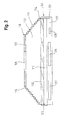
- Fig. 1 shows a schematic representation of a mobile document reader according to one embodiment.
- the mobile document reader comprises a document support 101 for receiving an in Fig. 1 not shown identification document.
- the mobile document reader comprises a camera receptacle 103, which comprises a camera opening 105 for capturing an image objective 107 of an image camera 109.
- the mobile document reader further comprises an opaque bellows 111, which foldably extends between the document support 101 and the camera mount 103 and is designed to form or enclose an image receiving space 113 between the document support 101 and the camera mount 103.
- the opaque bladder 111 includes a first circumferential edge 114 and a second circumferential edge 115.
- the opaque bellows 111 is connected to the document support 101 with its first peripheral edge 114.
- the second circumferential edge 115 is connected to the camera recording.
- the peripheral edges 114 and 115 define two-sided openings of the opaque bellows.
- the image receiving space 113 is thus crossed by the light-impermeable bellows 111 on the one hand and down through the document support 101 and up through the camera mount 103. In this way, it is possible to shield the image receiving space from external stray light.
- the document support 101 comprises a base plate 117 and a light-transparent window 118, for example a light-transparent plate, which are arranged above the base plate 117. Between the base plate 117 and the light transparent window 118, a receiving space 119 for the identification document is formed. The identification document is inserted for the reception in the receiving space 119, so that the identification document on the one hand by the base plate 117 and on the other hand covered by the transparent window 118. Thus, the identification document can be optically detected by means of the image camera 109.
- the light transparent window 118 is connected to the base plate by means of a hinge 121. In this way, the light transparent window 118 can be pivoted. If the opaque bladder 111 is connected to the light transparent window 118, the opaque bellows 111 can be opened together with the light transparent window 118, so that the identification document inserted into the receiving space 111 and clamped and fixed at a pivoting back of the light transparent window 118 therethrough can.
- the light transparent window 118 may be detachably connected to the base plate 117 by means of a closure 123, for example by means of a locking closure 123.
- a control interface 125 is arranged, which, for example, for controlling a in Fig. 1 not shown illumination source for illumination of the identification document can be used.
- a lighting time can be set.
- the control interface 125 is preferably arranged in the base plate 117.
- the mobile document reader comprises a power source 127, for example a rechargeable battery, which is arranged in the base plate 117.
- the energy source 127 can be supplied, for example by means of an optional charging socket 129, which may also be formed in the base plate, with energy and thereby charged.
- the energy source 127 can be used, for example, to supply the in Fig. 1 not shown illumination source are used with electrical energy.
- the power source 127 may provide the control interface 125 with electrical energy.
- the camera receptacle 103 comprises, according to one embodiment, a carrier plate 131, which may be provided for holding the image objective 107.
- the support plate 131 is for example opaque, wherein the camera opening 105 may be formed in the support plate 131.
- the support plate 131 can be provided, for example, the image camera 109 or a mobile communication device that contains the image camera 109, for example, a smartphone in which Fig. 1 to support dashed lines shown schematically manner.
- the communication device can be placed on the carrier plate 131, so that the image objective 107 is inserted into the camera opening 105 or positioned above it, so that optical recording of the identification document arranged underneath the light-transparent window 118 is possible.
- the in Fig. 1 not shown illumination source such as an LED
- the illumination source in the region of the base plate 117, which forms a bottom plate can be attached.
- a direct coupling of the light for illuminating the identification document into the light-transparent window 117 can be realized.
- the light-transparent window 118 can comprise, for example, a Fresnel lens, which directs the exiting light in the direction of the identification document when the light emerges.
- the opaque bladder 111 is fixed to the support plate 131 and can be lifted or tightened with this. This creates the clamped image receiving space 113, which is, for example, a pyramid or truncated cone.
- the opaque bellows may in this case comprise, for example, a flexible material web, such as stage molton, which connects the carrier plate 131 and the translucent window 118 or the base plate 117.
- the opaque bladder 111 is pulled apart, whereby the image receiving space 113 is formed, in which an image recording of the identification document can be generated without disturbing light influences from the outside.
- the in Fig. 1 shown document readers are merged as it is in Fig. 2 is shown.
- the opaque bellows 111 in the in Fig. 2 be shown folded. If the opaque bladder 111 comprises interconnected, foldable plates, this can, as exemplified in Fig. 2 shown, merged. With the use of foldable plates, the stability of the opaque bladder 111 can be increased.
- Fig. 3 shows a plan view of the in the Fig. 1 and 2 shown mobile document reader, in which the first, lower, circumferential edge 114 and the upper peripheral edge 115 are each formed rectangular.
- the circulations of the peripheral edges 114, 115 are different, so that the light-impermeable bellows 111 in the direction of the opening 105 tapers in a pyramid shape.
Landscapes
- Engineering & Computer Science (AREA)
- Physics & Mathematics (AREA)
- General Physics & Mathematics (AREA)
- Multimedia (AREA)
- Computer Vision & Pattern Recognition (AREA)
- Theoretical Computer Science (AREA)
- Artificial Intelligence (AREA)
- Signal Processing (AREA)
- Facsimile Scanning Arrangements (AREA)
- Studio Devices (AREA)
- Accessories Of Cameras (AREA)
Abstract
Description
- Die vorliegende Erfindung betrifft das Gebiet der optischen Dokumentenerfassung.
- Zur optischen Erfassung eines Identifikationsdokumentes, beispielsweise eines Reisepasses oder eines Personalausweises, werden üblicherweise stationäre Dokumentenlesegeräte benutzt. Derartige Dokumentenlesegeräte sind üblicherweise ausgestattet mit einer transparenten Dokumentenauflage, auf welche ein Identifikationsdokument auflegbar ist, sowie einer Bildkamera zur Aufnahme eines optischen Bildes des Identifikationsdokumentes. Anhand des optischen Bildes des Identifikationsdokumentes können sowohl Personendaten als auch die Echtheit des Identifikationsdokumentes erfasst bzw. überprüft werden. Stationäre Dokumentenlesegeräte können zwar in unterschiedlichen Wellenlängenbereichen, beispielsweise bei Infrarotlicht, eingesetzt werden. Zudem können sie gegen Störlicht abgeschirmt werden. Stationäre Dokumentenlesegeräte eigenen sich jedoch nicht für einen mobilen Einsatz, beispielsweise im Rahmen einer polizeilichen Personenüberprüfung.
- Mobile Bildaufnahmen sind zwar mittels einer Bildkamera, beispielsweise mittels einer Kamera eines Smartphones, prinzipiell möglich. Derartige Bildaufnahmen sind jedoch stark anfällig für Störlicht.
- Es ist daher die Aufgabe der vorliegenden Erfindung, ein Konzept zur mobilen Dokumentenerfassung mit einer reduzierten Störlichtanfälligkeit zu schaffen.
- Diese Aufgabe wird durch die Merkmale der unabhängigen Ansprüche gelöst. Vorteilhafte Weiterbildungsformen sind Gegenstand der abhängigen Ansprüche, der Beschreibung sowie der beigefügten Figuren.
- Die vorliegende Erfindung basiert auf der Erkenntnis, dass die obige Aufgabe durch die Verwendung eines lichtundurchlässigen, beispielsweise faltbaren oder ausziehbaren Balges, gelöst werden kann, welche einen Raum zwischen einer Kamera und einem Identifikationsdokument gegen Fremd- bzw. Störlicht abschirmt. Innerhalb dieses abgeschirmten Raumes kann das Identifikationsdokument gezielt mit Licht einer vorbestimmten Wellenlänge, beispielsweise mit Infrarotlicht, Ultraviolettlicht oder Weißlicht, beleuchtet werden. Der undurchlässige Balg ist bevorzugt zusammenlegbar bzw. zusammenfaltbar, so dass ein Dokumentenlesegerät, welches mit dem lichtundurchlässigen Balg ausgestattet ist, transportierbar und daher mobil einsetzbar ist.
- Gemäß einem Aspekt wird ein mobiler Dokumentenleser für die optische Erfassung eines Identifikationsdokumentes mittels einer Bildkamera offenbart, mit einer Dokumentenauflage für die Aufnahme des Identifikationsdokumentes, einer Kameraaufnahme mit einer Kameraöffnung zur Aufnahme eines Bildobjektivs und einem lichtundurchlässigen Balg, welcher sich zwischen der Dokumentenauflage und der Kameraaufnahme faltbar erstreckt und ausgebildet ist, einen Bildaufnahmeraum zwischen der Dokumentenauflage und der Kameraaufnahme zu bilden.
- Der Begriff "lichtundurchlässig" bedeutet, dass die Intensität eines Lichts in einem Wellenlängenbereich, beispielsweise in einem Infrarot-Wellenlängenbereich, Ultraviolett-Wellenlängenbereich oder Weißlicht-Wellenlängenbereich, durch den lichtundurchlässigen Balg reduziert wird, so dass das Licht durch den lichtundurchlässigen Balg mit einer geringeren Intensität durchtritt oder nicht durchgelassen wird.
- Gemäß einer Ausführungsform weist der lichtundurchlässige Balg einen ersten umlaufenden Rand und einen zweiten umlaufenden Rand auf, wobei der erste umlaufende Rand mit der Dokumentenauflage, insbesondere mit einem umlaufenden Rand der Dokumentenauflage, verbunden ist, und wobei der zweite umlaufende Rand mit der Kameraaufnahme, insbesondere mit einem umlaufenden Rand der Kameraaufnahme, gebildet ist.
- Der lichtundurchlässige Balg umschließt somit den ersten umlaufenden Rand und den zweiten umlaufenden Rand und bildet einen abgeschirmten Raum zwischen dem ersten umlaufenden Rand und dem zweiten umlaufenden Rand. Hierbei kann sich der lichtundurchlässige Balg beispielsweise röhrenförmig zwischen dem ersten umlaufenden Rand und dem zweiten umlaufenden Rand erstrecken. Die durch den undurchlässigen Balg gebildete, äußere geometrische Form kann durch die geometrische Form des jeweiligen umlaufenden Randes bestimmt werden. Sind die umlaufenden Ränder beispielsweise rechteckförmig, so erstreckt sich der abgeschirmte Bildaufnahmeraum zwischen den Rändern ebenfalls rechteckförmig, d.h. mit einem rechteckförmigen Querschnitt. Sind die Randumfänge der umlaufenden Ränder unterschiedlich, so kann der lichtundurchlässige Balg beispielsweise einen pyramidenförmigen Bildaufnahmeraum umschließen, welcher sich zwischen den beiden Rändern erstreckt. Dadurch wird es möglich, das Identifikationsdokument in den Bildaufnahmeraum einzuführen.
- Gemäß einer Ausführungsform sind der erste umlaufende Rand und/oder der zweite umlaufende Rand kreisförmig, ellipsenförmig oder rechteckförmig.
- Gemäß einer Ausführungsform weist der zweite Rand einen geringeren Randumfang als der erste Rand auf. Dadurch erstreckt sich der lichtundurchlässige Balg beispielsweise pyramidenförmig oder trichterförmig in Richtung der Kameraaufnahme.
- Gemäß einer Ausführungsform umfasst der lichtundurchlässige Balg einen flexiblen Stoff. Dadurch kann der lichtundurchlässige Balg zusammengelegt werden.
- Gemäß einer Ausführungsform ist der lichtundurchlässige Balg zumindest teilweise faltbar, insbesondere in Richtung der Kameraöffnung faltbar. Auf diese Weise kann der lichtundurchlässige Balg zumindest teilweise harmonikaartig zusammengelegt werden.
- Gemäß einer Ausführungsform umfasst der lichtundurchlässige Balg eine Mehrzahl von faltbaren Platten oder Rahmen, insbesondere umlaufend angeordneten Platten oder umlaufenden Rahmen. Die faltbaren Platten sind beispielsweise lichtundurchlässig ausgebildet. Die faltbaren Platten können beispielsweise falzförmig miteinander verbunden sein. Die faltbaren Platten können beispielsweise aus Kunststoff bestehen, wobei ein flexibler Übergang zwischen benachbarten Platten durch eine Kunststoffverjüngung oder durch einen elastischen Kunststoff realisiert werden kann.
- Gemäß einer Ausführungsform ist der Balg manuell ausziehbar oder manuell zusammendrückbar oder manuell zusammenfaltbar. Durch die manuelle Betätigung des lichtundurchlässigen Balges kann dieser zusammengelegt oder ausgezogen werden. Gemäß einer Ausführungsform erstreckt sich der lichtundurchlässige Balg zwischen der Dokumentenauflage und der Kameraaufnahme zylinderförmig, quaderförmig, kegelförmig, insbesondere zur Kameraaufnahme hin zusammenlaufend kegelförmig, oder pyramidenförmig, insbesondere zur Kameraaufnahme hin zusammenlaufend pyramidenförmig. Durch die geometrische Form des lichtundurchlässigen Balges wird die geometrische Form des Bildaufnahmeraumes definiert. Auf diese Weise ist es möglich, unterschiedlich ausgebildete Dokumentenleser für unterschiedliche Verwendungszwecke, beispielsweise an bestimmten Größen von Identifikationsdokumente angepasst, zu realisieren.
- Gemäß einer Ausführungsform weist die Dokumentenauflage eine Grundplatte, insbesondere eine lichtundurchlässige Grundplatte und ein oberhalb der Grundplatte angeordnetes lichttransparentes Fenster auf, wobei das Identifikationsdokument in einen Aufnahmeraum zwischen der Grundplatte und dem lichttransparenten Fenster einführbar, insbesondere einklemmbar ist. Die lichtdurchlässige Grundplatte ist beispielsweise mit dem lichtdurchlässigen Balg verbunden, so dass beispielsweise bei einem Aufklappen des lichtundurchlässigen Balges die lichtdurchlässige Grundplatte mit aufgeklappt wird, so dass das Identifikationsdokument unter die lichtdurchsichtige Grundplatte gelegt werden kann bzw. durch diese gehalten werden kann.
- Gemäß einer Ausführungsform umfasst die Dokumentenauflage eine Beleuchtungsquelle zur Beleuchtung des Identifikationsdokumentes mit Licht, insbesondere in einem Weißlicht, Infrarotlicht oder Ultraviolettlicht. Die Beleuchtungsquelle kann beispielsweise an der Dokumentenauflage zur Durchleuchtung des Identifikationsdokumentes oder an der Kameraaufnahme zum Anstrahlen bzw. Anleuchten des Identifikationsdokumentes angebracht sein.
- Gemäß einer Ausführungsform umfasst die Dokumentenauflage eine Steuerungsschnittstelle zum Empfangen eines Steuersignals, insbesondere eines Synchronisationssignals, zur Steuerung der Beleuchtungsquelle. Die Steuerungsschnittstelle kann beispielsweise eine Kommunikationsschnittstelle, beispielsweise eine USB-Kommunikationsschnittstelle umfassen.
- Gemäß einer Ausführungsform umfasst die Steuerungsschnittstelle eine drahtlose Kommunikationsschnittstelle, insbesondere eine Bluetooth- oder eine WLAN-Kommunikationsschnittstelle. Die drahtlose Kommunikationsschnittstelle kann beispielsweise einen Empfänger und/oder einen Sender aufweisen, um eine drahtlose Datenkommunikation mit beispielsweise einem Computer zu ermöglichen, welcher zur Steuerung des mobilen Dokumentenlesers, insbesondere zur Steuerung der Beleuchtungsquelle, eingesetzt werden kann.
- Gemäß einer Ausführungsform umfasst die Dokumentenauflage eine Energiequelle, insbesondere eine über eine an der Dokumentenauflage angeordnete Ladebuchse aufladbare Energiequelle. Die Energiequelle kann beispielsweise eine wiederaufladbare Batterie sein, welche über eine Ladebuchse des WLAN-Dokumentenlesers geladen werden kann.
- Gemäß einer Ausführungsform weist die Kameraaufnahme eine Trägerplatte auf, auf welcher die Bildkamera mit dem Bildobjektiv oder ein Kommunikationsgerät, insbesondere Smartphone, mit dem Bildobjektiv, anordenbar ist. Die Trägerplatte ist vorgesehen, die Bildkamera mit dem Bildobjektiv zu halten bzw. zu positionieren, so dass das Bildobjektiv in der Kameraöffnung angeordnet ist. Ist die Bildkamera ein Element eines mobilen Kommunikationsgerätes, wie beispielsweise eines Smartphones, so kann die Trägerplatte vorgesehen sein, das Smartphone zu haltern, so dass das Bildobjektiv in der Kameraöffnung angeordnet ist. Auf diese Weise ist es möglich, das Identifikationsdokument ohne störendes Störlicht mittels eines mobilen Kommunikationsgerätes zu erfassen.
- Weitere Ausführungsbeispiele der Erfindung werden Bezug nehmend auf die beiliegenden Zeichnungen näher erläutert. Es zeigen:
- Fig. 1
- eine schematische Darstellung eine mobilen Dokumentenlesers;
- Fig. 2
- eine schematische Darstellung des Dokumentenlesers aus
Fig. 1 mit zusammengelegtem lichtundurchlässigen Balg; und - Fig.3
- eine Draufsicht auf einen lichtdurchsichtigen Balg gemäß einer Ausführungsform.
-
Fig. 1 zeigt eine schematische Darstellung eines mobilen Dokumentenlesers gemäß einer Ausführungsform. Der mobile Dokumentenleser umfasst eine Dokumentenauflage 101 für die Aufnahme eines inFig. 1 nicht dargestellten Identifikationsdokumentes. Ferner umfasst der mobile Dokumentenleser eine Kameraaufnahme 103, welche eine Kameraöffnung 105 für die Aufnahme eines Bildobjektivs 107 einer Bildkamera 109 umfasst. - Der mobile Dokumentenleser umfasst ferner einen lichtundurchlässigen Balg 111, welcher sich zwischen der Dokumentenauflage 101 und der Kameraaufnahme 103 faltbar erstreckt und ausgebildet ist, einen Bildaufnahmeraum 113 zwischen der Dokumentenauflage 101 und der Kameraaufnahme 103 zu bilden bzw. zu umschließen.
- Der lichtundurchlässige Balg 111 umfasst einen ersten umlaufenden Rand 114 und einen zweiten umlaufenden Rand 115.
- Der lichtundurchlässige Balg 111 ist mit seinem ersten umlaufenden Rand 114 mit der Dokumentenauflage 101 verbunden. Der zweite umlaufende Rand 115 ist hingegen mit der Kameraaufnahme verbunden. Die umlaufenden Ränder 114 und 115 definieren beidseitige Öffnungen des lichtundurchlässigen Balges. Der Bildaufnahmeraum 113 wird somit durch den lichtundurchlässigen Balg 111 einerseits sowie nach unten hin durch die Dokumentenauflage 101 und nach oben hin durch die Kameraaufnahme 103 verschränkt. Auf diese Weise ist es möglich, den Bildaufnahmeraum gegen äußeres Störlicht abzuschirmen.
- Die Dokumentenauflage 101 umfasst eine Grundplatte 117 sowie ein lichttransparentes Fenster 118, beispielsweise eine lichttransparente Platte, welche oberhalb der Grundplatte 117 angeordnet sind. Zwischen der Grundplatte 117 und dem lichttransparenten Fenster 118 ist ein Aufnahmeraum 119 für das Identifikationsdokument gebildet. Das Identifikationsdokument wird für die Aufnahme in den Aufnahmeraum 119 eingelegt, so dass das Identifikationsdokument einerseits durch die Grundplatte 117 und andererseits durch das durchsichtige Fenster 118 bedeckt ist. Somit kann das Identifikationsdokument mittels der Bildkamera 109 optisch erfasst werden.
- Gemäß einer Ausführungsform ist das lichttransparente Fenster 118 mittels eines Scharniers 121 mit der Grundplatte verbunden. Auf diese Weise kann das lichttransparente Fenster 118 verschwenkt werden. Ist der lichtundurchlässige Balg 111 mit dem lichttransparenten Fenster 118 verbunden, so kann der lichtundurchlässige Balg 111 zusammen mit dem lichttransparenten Fenster 118 aufgeklappt werden, so dass das Identifikationsdokument in den Aufnahmeraum 111 eingelegt und bei einem Zurückschwenken des lichttransparenten Fensters 118 durch dieses eingeklemmt und fixiert werden kann. Gemäß einer Ausführungsform kann das lichttransparente Fenster 118 mit der Grundplatte 117 mittels eines Verschlusses 123, beispielsweise mittels eines Verriegelungsverschlusses 123, lösbar verbunden werden.
- Gemäß einer Ausführungsform ist in der Grundplatte 117 eine Steuerungsschnittstelle 125 angeordnet, welche beispielsweise zur Steuerung einer in
Fig. 1 nicht dargestellten Beleuchtungsquelle zur Beleuchtung des Identifikationsdokumentes verwendet werden kann. Hierbei kann beispielsweise ein Beleuchtungszeitpunkt festgelegt werden. Die Steuerungsschnittstelle 125 ist bevorzugt in der Grundplatte 117 angeordnet. - Gemäß einer Ausführungsform umfasst der mobile Dokumentenleser eine Energiequelle 127, beispielsweise einen Akku, welcher in der Grundplatte 117 angeordnet ist. Die Energiequelle 127 kann beispielsweise mittels einer optionalen Ladebuchse 129, welche ebenfalls in der Grundplatte gebildet sein kann, mit Energie versorgt und dadurch aufgeladen werden. Die Energiequelle 127 kann beispielsweise zur Versorgung der in
Fig. 1 nicht dargestellten Beleuchtungsquelle mit elektrischer Energie herangezogen werden. Darüber hinaus kann die Energiequelle 127 die Steuerungsschnittstelle 125 mit elektrischer Energie versorgen. - Die Kameraaufnahme 103 umfasst gemäß einer Ausführungsform eine Trägerplatte 131, welche zur Halterung des Bildobjektives 107 vorgesehen sein kann. Die Trägerplatte 131 ist beispielsweise lichtundurchlässig, wobei die Kameraöffnung 105 in der Trägerplatte 131 gebildet sein kann. Die Trägerplatte 131 kann beispielsweise vorgesehen sein, die Bildkamera 109 bzw. ein mobiles Kommunikationsgerät, das die Bildkamera 109 enthält, beispielsweise ein Smartphone, in der in
Fig. 1 gestrichelt schematisch dargestellten Weise zu haltern. Hierbei kann das Kommunikationsgerät auf die Trägerplatte 131 aufgelegt werden, so dass das Bildobjektiv 107 in die Kameraöffnung 105 eingeführt bzw. über dieser positioniert wird, so dass eine optische Aufnahme des unterhalb der lichttransparenten Fensters 118 angeordneten Identifikationsdokumentes möglich ist. - An der Trägerplatte 131 kann die in
Fig. 1 nicht dargestellte Beleuchtungsquelle, beispielsweise eine LED, zur Beleuchtung des Identifikationsdokumentes angebracht werden. Wie vorstehend ausgeführt, kann die Beleuchtungsquelle im Bereich der Grundplatte 117, welche eine Bodenplatte bildet, angebracht werden. Gemäß einer weiteren Ausführungsform kann ein direktes Einkoppeln des Lichtes zur Beleuchtung des Identifikationsdokumentes in das lichttransparente Fenster 117 realisiert werden. Hierbei kann das lichttransparente Fenster 118 beispielsweise eine Fresnel-Linse umfassen, welche bei einem Lichtaustritt das austretende Licht in Richtung des Identifikationsdokumentes lenkt. - Gemäß einer Ausführungsform ist der lichtundurchlässige Balg 111 an der Trägerplatte 131 befestigt und kann mit dieser hochgehoben bzw. angezogen werden. Dadurch entsteht der aufgespannte Bildaufnahmeraum 113, welcher beispielsweise pyramiden- oder kegelstumpfförmig ist. Der lichtundurchlässige Balg kann hierbei beispielsweise eine flexible Stoffbahn, wie Bühnenmolton, umfassen, welche die Trägerplatte 131 und das lichtdurchsichtige Fenster 118 oder die Grundplatte 117 verbindet.
- In dem in
Fig. 1 dargestellten Ausführungsbeispiel ist der lichtundurchlässige Balg 111 auseinandergezogen, wodurch der Bildaufnahmeraum 113 entsteht, in welchem eine Bildaufnahme des Identifikationsdokumentes ohne störende Lichteinflüsse von außen erzeugt werden kann. - Nach Gebrauch kann der in
Fig. 1 dargestellte Dokumentenleser zusammengelegt werden, wie es inFig. 2 dargestellt ist. Dabei kann der lichtundurchlässige Balg 111 in der inFig. 2 dargestellten Weise zusammengefaltet sein. Umfasst der lichtundurchlässige Balg 111 miteinander verbundene, faltbare Platten, so kann dieser, wie beispielhaft inFig. 2 dargestellt, zusammengelegt werden. Bei der Verwendung von faltbaren Platten kann die Stabilität des lichtundurchlässigen Balges 111 erhöht werden. -
Fig. 3 zeigt eine Draufsicht auf den in denFig. 1 und2 dargestellten mobilen Dokumentenleser, bei dem der erste, untere, umlaufende Rand 114 und der obere umlaufende Rand 115 jeweils rechteckförmig ausgebildet sind. Dabei sind die Umläufe der umlaufenden Ränder 114, 115 unterschiedlich, so dass der lichtundurchlässige Balg 111 pyramidenförmig in Richtung der Öffnung 105 zuläuft. -
- 101
- Dokumentenauflage
- 103
- Kameraaufnahme
- 105
- Kameraöffnung
- 107
- Bildobjektiv
- 109
- Bildkamera
- 111
- Balg
- 113
- Bildaufnahmeraum
- 114
- erster umlaufender Rand
- 115
- zweiter umlaufender Rand
- 117
- Grundplatte
- 118
- Fenster, lichtdurchlässige Platte
- 119
- Aufnahmeraum
- 121
- Scharnier
- 123
- Verschluss
- 125
- Steuerungsschnittstelle
- 127
- Energiequelle
- 129
- Ladebuchse
- 131
- Trägerplatte
Claims (15)
- Mobiler Dokumentenleser für die optische Erfassung eines Identifikationsdokumentes mittels einer Bildkamera, mit:einer Dokumentenauflage (101) für die Aufnahme des Identifikationsdokumentes;einer Kameraaufnahme (103) mit einer Kameraöffnung zur Aufnahme eines Bildobjektivs; undeinem lichtundurchlässigen Balg (111), welcher sich zwischen der Dokumentenauflage (101) und der Kameraaufnahme (103) faltbar erstreckt und ausgebildet ist, einen Bildaufnahmeraum (113) zwischen der Dokumentenauflage (101) und der Kameraaufnahme (103) zu bilden.
- Mobiler Dokumentenleser nach Anspruch 1, wobei der lichtundurchlässige Balg (111) einen ersten umlaufenden Rand (114) und einen zweiten umlaufenden Rand (115) aufweist, wobei der erste umlaufende Rand (114) mit der Dokumentenauflage (101), insbesondere seitlich mit einem umlaufenden Rand der Dokumentenauflage (101), verbunden ist, und wobei der zweite umlaufende Rand (115) mit der Kameraaufnahme (103), insbesondere mit einem umlaufenden Rand der Kameraaufnahme (103), gebildet ist.
- Mobiler Dokumentenleser nach Anspruch 2, wobei erste umlaufende Rand (114) des lichtundurchlässigen Balges (111) mit der Dokumentenauflage (101) lösbar oder aufklappbar, insbesondere mittels eines Scharniers und/oder eines lösbaren Verschlusses, verbunden ist.
- Mobiler Dokumentenleser nach Anspruch 2 oder 3, wobei der zweite umlaufende Rand (115) einen geringeren Randumfang als der erste umlaufende Rand (114) aufweist.
- Mobiler Dokumentenleser nach einem der vorstehenden Ansprüche, wobei der lichtundurchlässige Balg (111) einen flexiblen Stoff umfasst.
- Mobiler Dokumentenleser nach einem der vorstehenden Ansprüche, wobei der lichtundurchlässige Balg (111) zumindest teilweise faltbar ist, insbesondere in Richtung der Kameraaufnahme (103) oder der Dokumentenauflage (101) faltbar ist.
- Mobiler Dokumentenleser nach einem der vorstehenden Ansprüche, wobei der lichtundurchlässige Balg (111) eine Mehrzahl von faltbaren Platten oder Rahmen, insbesondere umlaufend angeordneten Platten oder umlaufenden Rahmen umfasst.
- Mobiler Dokumentenleser nach einem der vorstehenden Ansprüche, wobei der lichtundurchlässige Balg (111) manuell ausziehbar oder manuell zusammendrückbar oder manuell zusammenfaltbar ist.
- Mobiler Dokumentenleser nach einem der vorstehenden Ansprüche, wobei der lichtundurchlässige Balg (111) sich zwischen der Dokumentenauflage (101) und der Kameraaufnahme (103) zylinderförmig, quaderförmig, kegelförmig, insbesondere zur Kameraaufnahme (103) hin zusammenlaufend kegelförmig, oder pyramidenförmig, insbesondere zur Kameraaufnahme (103) hin zusammenlaufend pyramidenförmig, erstreckt.
- Mobiler Dokumentenleser nach einem der vorstehenden Ansprüche, wobei die Dokumentenauflage (101) eine Grundplatte (117), insbesondere eine lichtundurchlässige Grundplatte (117), und ein oberhalb der Grundplatte (117) angeordnetes lichttransparentes Fenster (118) aufweist, wobei das Identifikationsdokument in einen Aufnahmeraum (119) zwischen der Grundplatte (117) und dem lichttransparenten Fenster (118) einführbar, insbesondere einklemmbar ist.
- Mobiler Dokumentenleser nach einem der vorstehenden Ansprüche, wobei die Dokumentenauflage (101) eine Beleuchtungsquelle zur Beleuchtung des Identifikationsdokumentes mit Licht, insbesondere in einem Weißlicht, Infrarotlicht oder Ultraviolettlicht, umfasst.
- Mobiler Dokumentenleser nach Anspruch 11, mit einer Steuerungsschnittstelle (125) zum Empfangen eines Steuersignals, insbesondere eines Synchronisationssignals, zur Steuerung der Beleuchtungsquelle.
- Mobiler Dokumentenleser nach Anspruch 12, wobei die Steuerungsschnittstelle (125) eine drahtlose Kommunikationsschnittstelle, insbesondere eine Bluetooth- oder eine WLAN-Kommunikationsschnittstelle umfasst.
- Mobiler Dokumentenleser nach einem der vorstehenden Ansprüche, wobei die Dokumentenauflage (101) eine Energiequelle (127), insbesondere eine über eine an der Dokumentenauflage (101) angeordnete Ladebuchse (129) aufladbare Energiequelle (127) umfasst.
- Mobiler Dokumentenleser nach einem der vorstehenden Ansprüche, wobei die Kameraaufnahme (103) eine Trägerplatte (131) aufweist, auf welcher die Bildkamera mit dem Bildobjektiv oder ein Kommunikationsgerät, insbesondere Smartphone, mit dem Bildobjektiv, anordenbar ist.
Applications Claiming Priority (1)
| Application Number | Priority Date | Filing Date | Title |
|---|---|---|---|
| DE102014113583.0A DE102014113583A1 (de) | 2014-09-19 | 2014-09-19 | Mobiler Dokumentenleser |
Publications (2)
| Publication Number | Publication Date |
|---|---|
| EP3002630A1 true EP3002630A1 (de) | 2016-04-06 |
| EP3002630B1 EP3002630B1 (de) | 2019-04-03 |
Family
ID=54185850
Family Applications (1)
| Application Number | Title | Priority Date | Filing Date |
|---|---|---|---|
| EP15185701.8A Active EP3002630B1 (de) | 2014-09-19 | 2015-09-17 | Mobiler dokumentenleser |
Country Status (2)
| Country | Link |
|---|---|
| EP (1) | EP3002630B1 (de) |
| DE (1) | DE102014113583A1 (de) |
Families Citing this family (1)
| Publication number | Priority date | Publication date | Assignee | Title |
|---|---|---|---|---|
| CN109375453A (zh) * | 2018-11-20 | 2019-02-22 | 中国航发贵州黎阳航空动力有限公司 | 一种可消除被拍摄物体反光反影的图像采集装置 |
Citations (4)
| Publication number | Priority date | Publication date | Assignee | Title |
|---|---|---|---|---|
| EP1026620A2 (de) * | 1999-02-05 | 2000-08-09 | Hewlett-Packard Company | Expandierbare Handabtastervorrichtung mit verkleinernder Linsenoptik |
| US20020105684A1 (en) * | 2001-01-24 | 2002-08-08 | Chih-Wen Huang | Contractible outer-shell apparatus of a scanning device |
| US20050134692A1 (en) * | 2003-12-18 | 2005-06-23 | Sharp Kabushiki Kaisha | Photographing assisting apparatus, photographing method, and photographing system |
| EP2566146A1 (de) * | 2011-09-01 | 2013-03-06 | ION Audio LLC | Photoscanner einer mobilen Vorrichtung |
Family Cites Families (2)
| Publication number | Priority date | Publication date | Assignee | Title |
|---|---|---|---|---|
| US3668991A (en) * | 1969-06-13 | 1972-06-13 | Polaroid Corp | Folding camera |
| DE3529036A1 (de) * | 1985-08-13 | 1986-03-06 | bbs AG, Mauren | Fotografische belichtungseinrichtung |
-
2014
- 2014-09-19 DE DE102014113583.0A patent/DE102014113583A1/de not_active Withdrawn
-
2015
- 2015-09-17 EP EP15185701.8A patent/EP3002630B1/de active Active
Patent Citations (4)
| Publication number | Priority date | Publication date | Assignee | Title |
|---|---|---|---|---|
| EP1026620A2 (de) * | 1999-02-05 | 2000-08-09 | Hewlett-Packard Company | Expandierbare Handabtastervorrichtung mit verkleinernder Linsenoptik |
| US20020105684A1 (en) * | 2001-01-24 | 2002-08-08 | Chih-Wen Huang | Contractible outer-shell apparatus of a scanning device |
| US20050134692A1 (en) * | 2003-12-18 | 2005-06-23 | Sharp Kabushiki Kaisha | Photographing assisting apparatus, photographing method, and photographing system |
| EP2566146A1 (de) * | 2011-09-01 | 2013-03-06 | ION Audio LLC | Photoscanner einer mobilen Vorrichtung |
Also Published As
| Publication number | Publication date |
|---|---|
| EP3002630B1 (de) | 2019-04-03 |
| DE102014113583A1 (de) | 2016-03-24 |
Similar Documents
| Publication | Publication Date | Title |
|---|---|---|
| DE102015005304B3 (de) | Vorrichtung für ein portables Smart-Gerät | |
| DE102019108634A1 (de) | Fahrzeugbeleuchtungssystem, das Objektidentifizierung und Gefahrenpegelbewertung bietet | |
| DE102013112508A1 (de) | Mobilgeräteadapter für ein Mikroskop und bildgebendes mikroskopisches Verfahren, das den Mobilgeräteadapter verwendet | |
| DE202012013713U1 (de) | Vorrichtung zur Dual-Target-Autobelichtung | |
| DE19625767A1 (de) | Lesegerät für die optische Erfassung und Speicherung von visuell markierten und projizierten alphanumerischen Zeichen, Graphiken und fotografischen Bildern | |
| DE102016105818B4 (de) | Bilderfassungsgerät und elektronisches Gerät | |
| EP3002630B1 (de) | Mobiler dokumentenleser | |
| DE202019106022U1 (de) | Handhaltbare Vorrichtung zur Aufnahme von lebenden Hautbereichen menschlicher Autopodien und von Dokumenten | |
| EP1997646A3 (de) | Anlage und Verfahren zur Verarbeitung von Drucksachen | |
| EP2883191B1 (de) | Dokumentenlesegerät mit einer dokumentenauflage | |
| DE102018103233A1 (de) | Einstellungsunterstützungsapparat, bildverarbeitungssystem und einstellungsunterstützungsprogramm | |
| DE102012211076A1 (de) | Vorrichtung und Verfahren zur Dokumentenerfassung | |
| EP3047461B1 (de) | Dokumentenprüfgerät | |
| EP1483622B1 (de) | Auflagefläche eines geräts zur optischen aufnahme von objekten | |
| WO2004029864A1 (de) | Erfassen und greifen von gegenständen | |
| DE102014103633A1 (de) | Vorrichtung zur Interaktion mit zum Beispiel einem mobilen Endgerät | |
| EP2984635A1 (de) | Bildaufnahmesystem zur bildaufnahme eines merkmals eines identifikationsdokumentes | |
| DE3239995C2 (de) | Vorrichtung zum Erkennen von Dokumenten | |
| DE102013103527A1 (de) | Bildaufnahmesystem zur Bildaufnahme von Merkmalen eines Identifikationsdokumentes | |
| AT501662A1 (de) | Vorrichtung zum digitalen abbilden und speichern eines dokumentes | |
| DE102004043066B4 (de) | Farbcode zur Vorrichtungskonfiguration | |
| DE102007043243A1 (de) | Halbautomatisches Kopierstativ | |
| DE202020103084U1 (de) | Portabler Smartphone-Scanner | |
| McAvoy | Image processing applied to UV photo of the Shroud of Turin which includes the radiocarbon test area | |
| DE102010061302A1 (de) | Optische Vorrichtung, insbesondere Fernrohr oder Mikroskop |
Legal Events
| Date | Code | Title | Description |
|---|---|---|---|
| PUAI | Public reference made under article 153(3) epc to a published international application that has entered the european phase |
Free format text: ORIGINAL CODE: 0009012 |
|
| AK | Designated contracting states |
Kind code of ref document: A1 Designated state(s): AL AT BE BG CH CY CZ DE DK EE ES FI FR GB GR HR HU IE IS IT LI LT LU LV MC MK MT NL NO PL PT RO RS SE SI SK SM TR |
|
| AX | Request for extension of the european patent |
Extension state: BA ME |
|
| 17P | Request for examination filed |
Effective date: 20160926 |
|
| RBV | Designated contracting states (corrected) |
Designated state(s): AL AT BE BG CH CY CZ DE DK EE ES FI FR GB GR HR HU IE IS IT LI LT LU LV MC MK MT NL NO PL PT RO RS SE SI SK SM TR |
|
| STAA | Information on the status of an ep patent application or granted ep patent |
Free format text: STATUS: EXAMINATION IS IN PROGRESS |
|
| 17Q | First examination report despatched |
Effective date: 20180320 |
|
| RIC1 | Information provided on ipc code assigned before grant |
Ipc: G03B 17/56 20060101ALN20181031BHEP Ipc: G03B 15/06 20060101AFI20181031BHEP Ipc: G06K 9/24 20060101ALN20181031BHEP Ipc: H04N 1/00 20060101ALN20181031BHEP Ipc: G03B 27/32 20060101ALI20181031BHEP |
|
| GRAP | Despatch of communication of intention to grant a patent |
Free format text: ORIGINAL CODE: EPIDOSNIGR1 |
|
| STAA | Information on the status of an ep patent application or granted ep patent |
Free format text: STATUS: GRANT OF PATENT IS INTENDED |
|
| INTG | Intention to grant announced |
Effective date: 20181210 |
|
| GRAS | Grant fee paid |
Free format text: ORIGINAL CODE: EPIDOSNIGR3 |
|
| GRAA | (expected) grant |
Free format text: ORIGINAL CODE: 0009210 |
|
| STAA | Information on the status of an ep patent application or granted ep patent |
Free format text: STATUS: THE PATENT HAS BEEN GRANTED |
|
| AK | Designated contracting states |
Kind code of ref document: B1 Designated state(s): AL AT BE BG CH CY CZ DE DK EE ES FI FR GB GR HR HU IE IS IT LI LT LU LV MC MK MT NL NO PL PT RO RS SE SI SK SM TR |
|
| REG | Reference to a national code |
Ref country code: GB Ref legal event code: FG4D Free format text: NOT ENGLISH |
|
| REG | Reference to a national code |
Ref country code: CH Ref legal event code: EP Ref country code: AT Ref legal event code: REF Ref document number: 1116477 Country of ref document: AT Kind code of ref document: T Effective date: 20190415 |
|
| REG | Reference to a national code |
Ref country code: DE Ref legal event code: R096 Ref document number: 502015008528 Country of ref document: DE |
|
| REG | Reference to a national code |
Ref country code: IE Ref legal event code: FG4D Free format text: LANGUAGE OF EP DOCUMENT: GERMAN |
|
| REG | Reference to a national code |
Ref country code: NL Ref legal event code: MP Effective date: 20190403 |
|
| REG | Reference to a national code |
Ref country code: LT Ref legal event code: MG4D |
|
| PG25 | Lapsed in a contracting state [announced via postgrant information from national office to epo] |
Ref country code: NL Free format text: LAPSE BECAUSE OF FAILURE TO SUBMIT A TRANSLATION OF THE DESCRIPTION OR TO PAY THE FEE WITHIN THE PRESCRIBED TIME-LIMIT Effective date: 20190403 |
|
| PG25 | Lapsed in a contracting state [announced via postgrant information from national office to epo] |
Ref country code: CZ Free format text: LAPSE BECAUSE OF FAILURE TO SUBMIT A TRANSLATION OF THE DESCRIPTION OR TO PAY THE FEE WITHIN THE PRESCRIBED TIME-LIMIT Effective date: 20190403 Ref country code: PT Free format text: LAPSE BECAUSE OF FAILURE TO SUBMIT A TRANSLATION OF THE DESCRIPTION OR TO PAY THE FEE WITHIN THE PRESCRIBED TIME-LIMIT Effective date: 20190803 Ref country code: AL Free format text: LAPSE BECAUSE OF FAILURE TO SUBMIT A TRANSLATION OF THE DESCRIPTION OR TO PAY THE FEE WITHIN THE PRESCRIBED TIME-LIMIT Effective date: 20190403 Ref country code: FI Free format text: LAPSE BECAUSE OF FAILURE TO SUBMIT A TRANSLATION OF THE DESCRIPTION OR TO PAY THE FEE WITHIN THE PRESCRIBED TIME-LIMIT Effective date: 20190403 Ref country code: LT Free format text: LAPSE BECAUSE OF FAILURE TO SUBMIT A TRANSLATION OF THE DESCRIPTION OR TO PAY THE FEE WITHIN THE PRESCRIBED TIME-LIMIT Effective date: 20190403 Ref country code: HR Free format text: LAPSE BECAUSE OF FAILURE TO SUBMIT A TRANSLATION OF THE DESCRIPTION OR TO PAY THE FEE WITHIN THE PRESCRIBED TIME-LIMIT Effective date: 20190403 Ref country code: NO Free format text: LAPSE BECAUSE OF FAILURE TO SUBMIT A TRANSLATION OF THE DESCRIPTION OR TO PAY THE FEE WITHIN THE PRESCRIBED TIME-LIMIT Effective date: 20190703 Ref country code: SE Free format text: LAPSE BECAUSE OF FAILURE TO SUBMIT A TRANSLATION OF THE DESCRIPTION OR TO PAY THE FEE WITHIN THE PRESCRIBED TIME-LIMIT Effective date: 20190403 Ref country code: ES Free format text: LAPSE BECAUSE OF FAILURE TO SUBMIT A TRANSLATION OF THE DESCRIPTION OR TO PAY THE FEE WITHIN THE PRESCRIBED TIME-LIMIT Effective date: 20190403 |
|
| PG25 | Lapsed in a contracting state [announced via postgrant information from national office to epo] |
Ref country code: LV Free format text: LAPSE BECAUSE OF FAILURE TO SUBMIT A TRANSLATION OF THE DESCRIPTION OR TO PAY THE FEE WITHIN THE PRESCRIBED TIME-LIMIT Effective date: 20190403 Ref country code: RS Free format text: LAPSE BECAUSE OF FAILURE TO SUBMIT A TRANSLATION OF THE DESCRIPTION OR TO PAY THE FEE WITHIN THE PRESCRIBED TIME-LIMIT Effective date: 20190403 Ref country code: PL Free format text: LAPSE BECAUSE OF FAILURE TO SUBMIT A TRANSLATION OF THE DESCRIPTION OR TO PAY THE FEE WITHIN THE PRESCRIBED TIME-LIMIT Effective date: 20190403 Ref country code: BG Free format text: LAPSE BECAUSE OF FAILURE TO SUBMIT A TRANSLATION OF THE DESCRIPTION OR TO PAY THE FEE WITHIN THE PRESCRIBED TIME-LIMIT Effective date: 20190703 Ref country code: GR Free format text: LAPSE BECAUSE OF FAILURE TO SUBMIT A TRANSLATION OF THE DESCRIPTION OR TO PAY THE FEE WITHIN THE PRESCRIBED TIME-LIMIT Effective date: 20190704 |
|
| PG25 | Lapsed in a contracting state [announced via postgrant information from national office to epo] |
Ref country code: IS Free format text: LAPSE BECAUSE OF FAILURE TO SUBMIT A TRANSLATION OF THE DESCRIPTION OR TO PAY THE FEE WITHIN THE PRESCRIBED TIME-LIMIT Effective date: 20190803 |
|
| REG | Reference to a national code |
Ref country code: DE Ref legal event code: R097 Ref document number: 502015008528 Country of ref document: DE |
|
| PG25 | Lapsed in a contracting state [announced via postgrant information from national office to epo] |
Ref country code: DK Free format text: LAPSE BECAUSE OF FAILURE TO SUBMIT A TRANSLATION OF THE DESCRIPTION OR TO PAY THE FEE WITHIN THE PRESCRIBED TIME-LIMIT Effective date: 20190403 Ref country code: RO Free format text: LAPSE BECAUSE OF FAILURE TO SUBMIT A TRANSLATION OF THE DESCRIPTION OR TO PAY THE FEE WITHIN THE PRESCRIBED TIME-LIMIT Effective date: 20190403 Ref country code: EE Free format text: LAPSE BECAUSE OF FAILURE TO SUBMIT A TRANSLATION OF THE DESCRIPTION OR TO PAY THE FEE WITHIN THE PRESCRIBED TIME-LIMIT Effective date: 20190403 Ref country code: SK Free format text: LAPSE BECAUSE OF FAILURE TO SUBMIT A TRANSLATION OF THE DESCRIPTION OR TO PAY THE FEE WITHIN THE PRESCRIBED TIME-LIMIT Effective date: 20190403 |
|
| PLBE | No opposition filed within time limit |
Free format text: ORIGINAL CODE: 0009261 |
|
| STAA | Information on the status of an ep patent application or granted ep patent |
Free format text: STATUS: NO OPPOSITION FILED WITHIN TIME LIMIT |
|
| PG25 | Lapsed in a contracting state [announced via postgrant information from national office to epo] |
Ref country code: IT Free format text: LAPSE BECAUSE OF FAILURE TO SUBMIT A TRANSLATION OF THE DESCRIPTION OR TO PAY THE FEE WITHIN THE PRESCRIBED TIME-LIMIT Effective date: 20190403 Ref country code: SM Free format text: LAPSE BECAUSE OF FAILURE TO SUBMIT A TRANSLATION OF THE DESCRIPTION OR TO PAY THE FEE WITHIN THE PRESCRIBED TIME-LIMIT Effective date: 20190403 |
|
| 26N | No opposition filed |
Effective date: 20200106 |
|
| PG25 | Lapsed in a contracting state [announced via postgrant information from national office to epo] |
Ref country code: TR Free format text: LAPSE BECAUSE OF FAILURE TO SUBMIT A TRANSLATION OF THE DESCRIPTION OR TO PAY THE FEE WITHIN THE PRESCRIBED TIME-LIMIT Effective date: 20190403 |
|
| PG25 | Lapsed in a contracting state [announced via postgrant information from national office to epo] |
Ref country code: MC Free format text: LAPSE BECAUSE OF FAILURE TO SUBMIT A TRANSLATION OF THE DESCRIPTION OR TO PAY THE FEE WITHIN THE PRESCRIBED TIME-LIMIT Effective date: 20190403 Ref country code: SI Free format text: LAPSE BECAUSE OF FAILURE TO SUBMIT A TRANSLATION OF THE DESCRIPTION OR TO PAY THE FEE WITHIN THE PRESCRIBED TIME-LIMIT Effective date: 20190403 |
|
| REG | Reference to a national code |
Ref country code: CH Ref legal event code: PL |
|
| PG25 | Lapsed in a contracting state [announced via postgrant information from national office to epo] |
Ref country code: CH Free format text: LAPSE BECAUSE OF NON-PAYMENT OF DUE FEES Effective date: 20190930 Ref country code: LU Free format text: LAPSE BECAUSE OF NON-PAYMENT OF DUE FEES Effective date: 20190917 Ref country code: IE Free format text: LAPSE BECAUSE OF NON-PAYMENT OF DUE FEES Effective date: 20190917 Ref country code: LI Free format text: LAPSE BECAUSE OF NON-PAYMENT OF DUE FEES Effective date: 20190930 |
|
| REG | Reference to a national code |
Ref country code: BE Ref legal event code: MM Effective date: 20190930 |
|
| PG25 | Lapsed in a contracting state [announced via postgrant information from national office to epo] |
Ref country code: BE Free format text: LAPSE BECAUSE OF NON-PAYMENT OF DUE FEES Effective date: 20190930 |
|
| PG25 | Lapsed in a contracting state [announced via postgrant information from national office to epo] |
Ref country code: CY Free format text: LAPSE BECAUSE OF FAILURE TO SUBMIT A TRANSLATION OF THE DESCRIPTION OR TO PAY THE FEE WITHIN THE PRESCRIBED TIME-LIMIT Effective date: 20190403 |
|
| PG25 | Lapsed in a contracting state [announced via postgrant information from national office to epo] |
Ref country code: MT Free format text: LAPSE BECAUSE OF FAILURE TO SUBMIT A TRANSLATION OF THE DESCRIPTION OR TO PAY THE FEE WITHIN THE PRESCRIBED TIME-LIMIT Effective date: 20190403 Ref country code: HU Free format text: LAPSE BECAUSE OF FAILURE TO SUBMIT A TRANSLATION OF THE DESCRIPTION OR TO PAY THE FEE WITHIN THE PRESCRIBED TIME-LIMIT; INVALID AB INITIO Effective date: 20150917 |
|
| REG | Reference to a national code |
Ref country code: AT Ref legal event code: MM01 Ref document number: 1116477 Country of ref document: AT Kind code of ref document: T Effective date: 20200917 |
|
| PG25 | Lapsed in a contracting state [announced via postgrant information from national office to epo] |
Ref country code: AT Free format text: LAPSE BECAUSE OF NON-PAYMENT OF DUE FEES Effective date: 20200917 |
|
| PG25 | Lapsed in a contracting state [announced via postgrant information from national office to epo] |
Ref country code: MK Free format text: LAPSE BECAUSE OF FAILURE TO SUBMIT A TRANSLATION OF THE DESCRIPTION OR TO PAY THE FEE WITHIN THE PRESCRIBED TIME-LIMIT Effective date: 20190403 |
|
| P01 | Opt-out of the competence of the unified patent court (upc) registered |
Effective date: 20230526 |
|
| PGFP | Annual fee paid to national office [announced via postgrant information from national office to epo] |
Ref country code: DE Payment date: 20250919 Year of fee payment: 11 |
|
| PGFP | Annual fee paid to national office [announced via postgrant information from national office to epo] |
Ref country code: GB Payment date: 20250923 Year of fee payment: 11 |
|
| PGFP | Annual fee paid to national office [announced via postgrant information from national office to epo] |
Ref country code: FR Payment date: 20250924 Year of fee payment: 11 |