EP3002394A1 - Mast mit abspannung - Google Patents
Mast mit abspannung Download PDFInfo
- Publication number
- EP3002394A1 EP3002394A1 EP15002814.0A EP15002814A EP3002394A1 EP 3002394 A1 EP3002394 A1 EP 3002394A1 EP 15002814 A EP15002814 A EP 15002814A EP 3002394 A1 EP3002394 A1 EP 3002394A1
- Authority
- EP
- European Patent Office
- Prior art keywords
- mast
- cable
- cables
- auxiliary
- traction
- Prior art date
- Legal status (The legal status is an assumption and is not a legal conclusion. Google has not performed a legal analysis and makes no representation as to the accuracy of the status listed.)
- Granted
Links
Images


Classifications
-
- E—FIXED CONSTRUCTIONS
- E04—BUILDING
- E04H—BUILDINGS OR LIKE STRUCTURES FOR PARTICULAR PURPOSES; SWIMMING OR SPLASH BATHS OR POOLS; MASTS; FENCING; TENTS OR CANOPIES, IN GENERAL
- E04H12/00—Towers; Masts or poles; Chimney stacks; Water-towers; Methods of erecting such structures
- E04H12/02—Structures made of specified materials
- E04H12/08—Structures made of specified materials of metal
- E04H12/10—Truss-like structures
-
- E—FIXED CONSTRUCTIONS
- E04—BUILDING
- E04H—BUILDINGS OR LIKE STRUCTURES FOR PARTICULAR PURPOSES; SWIMMING OR SPLASH BATHS OR POOLS; MASTS; FENCING; TENTS OR CANOPIES, IN GENERAL
- E04H12/00—Towers; Masts or poles; Chimney stacks; Water-towers; Methods of erecting such structures
- E04H12/20—Side-supporting means therefor, e.g. using guy ropes or struts
Definitions
- the present invention relates to a mast with at least two supports which are mechanically connected to each other, and which can be tensioned by tension cables.
- Poles with multiple supports also commonly called corner posts, which are mechanically connected to each other, by means of struts or the like, are well known.
- Such masts are commonly referred to as lattice masts. They can be used in a variety of ways, such as, for example, as antenna masts, for the height-appropriate placement of measuring devices, such as, for example, for determining wind speed, air temperature, air humidity or the like.
- masts can have very different lengths. From a certain length, it makes sense or necessary to make one or more guying. As a result, the reliability can be significantly increased, especially when acting through wind corresponding loads. These act substantially linearly on the masts, so that it can be tilted to a wind repellent direction. However, it is also possible that a torsional force acts on the masts by the influence of wind or the like, as a result of which it can be correspondingly twisted and possibly also damaged.
- the patent 316 956 relates to a tower for wireless telegraphy, which may have, for example, a triangular or a quadrangular floor plan.
- the subject of the local invention is a bracing that eliminates this moment while maintaining the rotation assurance by a cable fork. To do this placed by the center of gravity of the cross section of the mast at the guying rods. At this train cables are fastened by a fork so that the traction cables are directed to this center of gravity.
- the additional patent 429 237 is also provided that only a rope or a part of the ropes is connected with a fork to the mast, while the other ropes attack directly without fork in the center of gravity of the mast cross-section.
- ropes on the one hand, which are used as tension cables and which are struck at the geometric center of gravity of the horizontal mast geometry.
- the horizontal guest geometry refers to the stationary masts used in normal operation.
- auxiliary ropes which take over only the function of possibly necessary rotation assurance.
- the auxiliary ropes can be struck so that they an inadmissible rotation of the mast prevent and do not have to absorb tensile forces of the guy rope.
- These auxiliary ropes can therefore have a lot. That is, they are stretched during normal operation of the mast so far that in them a mechanical tension occurs only when torsional forces acting on the masts, exceeding a certain amount.
- the mast which may have two, three, four or more uprights (corner posts) connected together by means of respective struts, has a mechanical element connected to at least two of these struts.
- This element contains a connecting element that is located substantially centrally in the geometric center of gravity of the horizontal mast geometry.
- the connecting element can be designed in many ways, such as, for example, as an eye bolt, as a curved element or the like. It is particularly advantageous if it allows that the hinged thereto by means of associated fasteners traction cables are hinged.
- the individual elements of the mast are preferably made of steel, stainless steel or other suitable material.
- the traction cables and auxiliary ropes are made of material of suitable strength, such as steel, stainless steel, plastic or the like.
- the mast according to the invention is composed of several mast elements. So he can reach very different lengths as needed. It has proven itself, if the mechanical element, to the said cables are fixed, is arranged between two of these mast elements.
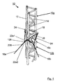
- Fig. 1 shows a perspective view of a lattice mast 10 with a bracing.
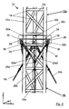
- Fig. 2 shows it - in side view - a section around the bracing around, with more details are provided with reference characters.
- agents that are present several times partially provided with a single reference (such as 14 for the cross struts).
- reference signs such as 16a, 16b, 16c for the various traction cables, etc.).
- the in Fig. 1 shown lattice mast 10 has three supports 12, which are also commonly called corner handles and are interconnected by a series of cross braces 14.
- the lattice mast 10 depending on its length, consists of a multiplicity of essentially identical mast elements, of which a top mast element 10a and a lower mast element 10b are symbolically marked here.
- the lattice mast 10 is in the ready state on a surface (not shown here), such as on the ground, a building or the like. It is suitable for various devices (not shown here) too wear, such as measuring devices, radio antennas and / or the like.
- the lattice mast 10 is tensioned by three tension cables 16a, 16b, 16c.
- traction cables 16a, 16b, 16c are connected at suitable locations and by suitable means to the ground or other points which have the necessary stability to absorb the forces for the bracing.
- Each of the traction cables 16a, 16b, 16c is also connected in the preferred embodiment, in each case with two auxiliary ropes 22, of which in the figures, only the auxiliary ropes 22a1 and 22a2 leading to the traction cable 16a are provided with reference marks.
- the upper ends of the auxiliary cables 22 are connected at their upper end in each case via a cable tensioner 24 with holders 26, which are located in the outer region of the cable plate 18 (see also FIG Fig. 2 . 3, 4 ).
- Each of the traction cables 16a, 16b, 16c has an upper cable clamp 28a and a lower cable clamp 28b. These cable clamps 28 serve to connect one of the traction ropes 16 to the associated pair of auxiliary ropes 22.
- the traction cable 16a is connected to the two auxiliary ropes 22a1 and 22a2 which are wound around the traction cable 16a between the cable clamps 28a and 28b and / or parallel to this.
- Fig. 2 shows a side view of the lattice mast 10. Means which have already been described, will be discussed here only insofar as it is important for the understanding of the present invention.
- a region 30 is marked, which shows elements for mounting the traction cables 16 and the auxiliary cables 22 and is referred to below as a tensioning unit.
- Essential elements of this guy unit 30 are also shown in enlarged form in FIG Fig. 3 shown. Therefore, for the following explanations, both Fig. 2 as well Fig. 3 directed.
- Fig. 2 a coordinate system x, y, z drawn, which is always referred to in the further figures, if it makes sense for the description of the invention.
- the lattice mast 10 extends along the z-axis and the cable plate 18 substantially in the xy plane.
- the tensioning unit 30 comprises in particular the cable plate 18 and three flanges 32a, b, c, which are designed such that they can receive the supports 12 of the upper mast element 10a from above and the supports 12 of the lower part of the mast element 10b from below.
- the flanges 32a, b, c and the associated supports 12a, b, c can be fixed by means of associated screw 34.
- a ring-like fastening element 40a, b, c is attached at its upper end, by means of which the associated traction cable 16 can be connected to the ring 38.
- a shackle is provided for this purpose.
- carbines or the like are also conceivable.
- Fig. 5 shows as a symbolic cross-sectional representation along the line AA ( Fig. 4 ) the attachment of the traction cables 16 a, b, c to the rope plate 18 in the attachment point 20th
- the embodiment described allows a guy, in which the three traction cables 16 are all attached to the geometric center of gravity of the mast geometry in the x-y plane; with the mast mounted vertically, this corresponds to the center of gravity of the horizontal mast geometry.
- This makes it possible that the force introduction of the traction cables 16 is always in this focus not only ideal but also under real conditions.
- By the auxiliary cables 22 is also made possible that an inadmissible rotation of the lattice mast 10 is prevented.
- the tension of the auxiliary ropes 22 is adjusted so that they are in the normal operation of the lattice mast 10 first - that is, without the action of a torsional force on the lattice masts 10 - are mounted without mechanical stress and therefore do not absorb tensile forces.
- a torsional force occurs - for example in a clockwise direction, cause the corresponding auxiliary cables 22 - in the example mentioned the auxiliary cables 22a1, 22b1, 22c1 that only a limited rotation of the lattice mast 10 is possible and further inadmissible rotation of the lattice mast 10 can be prevented.
- the auxiliary cables 22 are thus mounted in the preferred embodiment so that they have a lot.
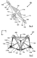
- Fig. 6, 7 show an alternative solution to the cable plate 18, namely a star-like element 110, which is hereinafter called Seilstern and preferably consists of metal.
- Fig. 6 shows a perspective view of the cable star 110 and
- Fig. 7 shows a plan view with associated bracing.
- the cable star 110 has three wing elements 112, which are designed substantially the same and are arranged at an angle of 120 degrees from each other.
- the holding elements 118 are arranged such that they are rotated relative to the stiffening elements 115 by 60 degrees.
- the arcuate structure creates three openings 121, of which only two in Fig. 6 are visible. Through each of these openings 121, a fastener, such as shackle, eyelet or the like can be performed so as to attach one of the three tension cables 116a, b, c (s. Fig. 7 ).
- a fastener such as shackle, eyelet or the like can be performed so as to attach one of the three tension cables 116a, b, c (s. Fig. 7 ).
- each wing element 112 In the outer region of the wing elements 112 are each two slots 126. These serve to connect auxiliary cables 122 with the cable star 110. Thereof are in Fig. 7 For reasons of clarity, only the two auxiliary ropes 122a1 and 122a2 are provided with reference marks. Furthermore, each wing element 112 has a ventilation opening 128, around which in each case three screw openings 130 are arranged. This makes it possible for support tubes of a mast element present above the cable star 110 and / or support tubes of a mast element present below the cable star 110 to be placed on the cable star from above or below and fastened by means of suitable screws which are guided through the screw holes 130 can.
- the ventilation holes 128 serve to ensure that the usually open ends of these support tubes also remain open in the region of the cable star 110, so that moisture, liquid or the like is not jammed and thus can not cause corrosion.
- the support tubes described here it is assumed that they each have a flange at their ends which protrudes laterally like a collar, as shown by the three flanges 132 in FIG Fig. 7 indicated. Also, in Fig. 7 three struts 134 are shown, which belong to the above the rope star 110 existing mast section.
- the point marked 200 corresponds to the geometric center of gravity of the cable star 110 within the xy plane and thus of the associated horizontal section (relative to normal operation) of the lattice mast 10.
- Fig. 7 It is also shown that the connection between the traction cables 116 and the associated auxiliary cables 122 is different than in the previous embodiment ( Fig. 1-5 ). For clarity shows Fig. 8 an enlargement of the in Fig. 7 marked area 136.
- the pull cord 116a is not continuous from the geometric center of gravity of the mast to a near-earth area.
- the traction cable consists of the upper part 116a and a lower part 216a, which are interconnected within the connection region 136.
- the upper part 116a has an eyelet 150a and the lower part has an eyelet 250a. Both eyelets 150a, 250a are connected to each other via a shackle 138a.
- the lower part of the auxiliary cable 122a1 is connected to an eyelet 152a1, and the lower part of the auxiliary cable 122a2 is connected to an eyelet 152a2.
- the two eyelets 152a1,152a2 are also connected to the shackle 138.
- the auxiliary cables 122a1, 122a2 are also connected to the pull cable 116a, 216a.
- the tension cable 116c has no associated auxiliary cables in this embodiment. Therefore, it is possible to easily climb the masts 10 on the relevant side.
- auxiliary cables 122 are tensioned by means of associated cable tensioner 124 so that only a limited rotation of the lattice mast 10 is possible and further inadmissible rotation of the lattice mast 10 can be prevented. That is, the auxiliary cables 122 are also mounted so as to have a lot.
Landscapes
- Engineering & Computer Science (AREA)
- Architecture (AREA)
- Civil Engineering (AREA)
- Structural Engineering (AREA)
- Life Sciences & Earth Sciences (AREA)
- Chemical & Material Sciences (AREA)
- Materials Engineering (AREA)
- Wood Science & Technology (AREA)
- Mutual Connection Of Rods And Tubes (AREA)
- Clamps And Clips (AREA)
- Support Of Aerials (AREA)
- Jib Cranes (AREA)
Description
- Die vorliegende Erfindung betrifft einen Mast mit mindestens zwei Stützen, die mechanisch miteinander verbunden sind, und der durch Spannseile abgespannt werden kann.
- Maste mit mehreren Stützen, allgemein auch Eckstiele genannt, die miteinander mechanisch verbunden sind, mittels Streben oder dergleichen, sind allgemein bekannt. Solche Maste werden üblicherweise als Gittermaste bezeichnet. Sie können vielfältig eingesetzt werden, wie beispielsweise als Antennenmaste, für die höhengerechte Platzierung von Messgeräten, wie beispielsweise zur Ermittlung von Windgeschwindigkeit, Lufttemperatur, Luftfeuchte oder dergleichen.
- Derartige Maste können je nach Anwendungsfall sehr unterschiedliche Längen aufweisen. Ab einer gewissen Länge ist es sinnvoll bzw. notwendig, eine oder mehrere Abspannungen vorzunehmen. Dadurch kann die Betriebssicherheit deutlich erhöht werden, insbesondere dann, wenn durch Wind entsprechende Lasten einwirken. Diese wirken im Wesentlichen linear auf den Masten ein, so dass dieser zu einer dem Wind abweisende Richtung geneigt werden kann. Es ist jedoch auch zusätzlich möglich, dass durch Windeinfluss oder Ähnlichem eine Torsionskraft auf den Masten einwirkt, wodurch dieser entsprechend verdreht und eventuell auch beschädigt werden kann.
- Verschiedene Maste mit entsprechenden Abspannungen sind beispielsweise bekannt aus der internationalen PCT-Veröffentlichung
WO 01/36766 A1 EP 1 270 848 B1 sowie aus der deutschen Patentschrift316 956 und dem zugehörigen Zusatzpatent429 237 - Das Patent
316 956 - Die bereits bekannte Lösung hat jedoch den Nachteil, dass keine momentenfreie Abspannung möglich ist.
- Es ist daher die Aufgabe der vorliegenden Erfindung, diesen Nachteil zu vermeiden.
- Diese Aufgabe wird gelöst durch die Erfindung nach dem Hauptanspruch. Durch die Unteransprüche sind vorteilhafte Weiterbildungen angegeben.
- Der vorliegenden Erfindung liegen folgende Erkenntnisse zugrunde. Bei der in dem Patent
429 237 - Bei der vorliegenden Erfindung hingegen gibt es einerseits Seile, die als Zugseile verwendet werden und die am geometrischen Schwerpunkt der horizontalen Mastgeometrie angeschlagen werden. Dabei bezieht sich die horizontale Gastgeometrie auf den stehenden Masten, der im Normalbetrieb verwendet wird. Außerdem gibt es Hilfsseile, die ausschließlich die Funktion der eventuell notwendigen Drehungssicherung übernehmen. Die Hilfsseile können so angeschlagen werden, dass sie eine unzulässige Verdrehung des Mastes verhindern und keine Zugkräfte des Abspannseils aufnehmen müssen. Diese Hilfsseile können also eine Lose haben. Das heißt, sie werden im Normalbetrieb des Mastes so weit gespannt, dass bei ihnen eine mechanische Spannung erst dann auftritt, wenn Torsionskräfte auf den Masten einwirken, die einen bestimmten Betrag überschreiten.
- Durch die erfindungsgemäße Funktionstrennung von Zugseilen und Hilfsseilen wird erreicht, dass die Krafteinbringung der Zugseile nicht nur idealen sondern auch unter realen Bedingungen immer im geometrischen Schwerpunkt der horizontalen Mastgeometrie erfolgt. Dadurch wird erreicht, dass alle Kräfte, die von den Seilen in axiale Richtung des Mastes umgelenkt werden, immer auf jedes Standrohr gleichmäßig aufgeteilt werden.
- Zur Realisierung der vorliegenden Erfindung weist der Mast, der zwei, drei, vier oder mehr Stützen (Eckstiele) aufweisen kann, die mittels entsprechender Streben miteinander verbunden sind, ein mechanisches Element auf, das verbunden ist mit mindestens zwei dieser Stützen. Dieses Element enthält ein Verbindungselement, das sich im Wesentlichen mittig im geometrischen Schwerpunkt der horizontalen Mastgeometrie befindet. Das Verbindungselement kann vielfältig gestaltet sein, wie beispielsweise als Ringschraube, als bogenförmiges Element oder dergleichen. Dabei ist es besonders vorteilhaft, wenn es erlaubt, dass die daran mittels zugehöriger Befestigungselemente angeschlagenen Zugseile gelenkig befestigt sind.
- Die einzelnen Elemente des Mastes bestehen bevorzugterweise aus Stahl, Edelstahl oder einem anderen geeigneten Material. Die Zugseile und Hilfsseilen bestehen aus Material geeigneter Festigkeit, wie Stahl, Edelstahl, Kunststoff oder dergleichen.
- In einer bevorzugten Ausgestaltung wird der erfindungsgemäße Mast aus mehreren Mastelementen zusammengesetzt. Damit kann er je nach Bedarf sehr verschiedene Längen erreichen. Dabei hat es sich bewährt, wenn das mechanische Element, an dem die genannten Seile befestigt sind, zwischen zwei dieser Mastelemente angeordnet wird.
- Weitere Einzelheiten und Vorteile der vorliegenden Erfindung werden im Folgenden anhand von bevorzugten Ausführungsbeispielen mit zugehörigen Abbildungen erläutert. Dabei zeigen
- Fig. 1
- perspektivische Sicht auf einen Gittermast mit Abspannung
- Fig. 2
- Seitenansicht auf den Gittermast mit Abspannung
- Fig. 3
- Wesentliche Elemente der Abspanneinheit
- Fig. 4
- Draufsicht auf die Abspanneinheit
- Fig. 5
- symbolische Schnittdarstellung entlang der Linie A-A aus
Fig. 4 - Fig. 6
- perspektivische Sicht auf einen Seilstern
- Fig. 7
- Draufsicht auf einen Seilstern mit Verspannung
- Fig. 8
- vergrößerte Darstellung des Verbindungsbereiches 136 aus
Fig. 7 . -
Fig. 1 zeigt in perspektivischer Sicht einen Gittermast 10 mit einer Abspannung.Fig. 2 zeigt davon - in Seitenansicht - einen Ausschnitt um die Abspannung herum, wobei mehr Details mit Referenzzeichen versehen sind. Dabei wurden Mittel, die mehrfach vorhanden sind, teilweise mit einer einzigen Referenz versehen (wie beispielsweise 14 für die Querstreben). Soweit es für das Verständnis der vorliegenden Erfindung jedoch sinnvoll erscheint, wurden auch differenzierte Referenzzeichen verwendet (wie beispielsweise 16a, 16b, 16c für die verschiedenen Zugseile, usw.). - Der in
Fig. 1 gezeigte Gittermast 10 weist drei Stützen 12 auf, die allgemein auch Eckstiele genannt werden und untereinander durch eine Reihe von Querstreben 14 verbunden sind. Der Gittermast 10 besteht in Abhängigkeit von seiner Länge aus einer Vielzahl von im Wesentlichen baugleichen Mastelementen, von denen hier symbolisch ein oberes Mastelement 10a und ein unteres Mastelement 10b markiert sind. Der Gittermast 10 steht im betriebsbereiten Zustand auf einer Fläche (hier nicht dargestellt), wie beispielsweise auf dem Erdboden, einem Gebäude oder dergleichen. Er ist geeignet, verschiedene Vorrichtungen (hier nicht gezeigt) zu tragen, wie beispielsweise Messgeräte, Funkantennen und/oder dergleichen. Der Gittermast 10 wird durch drei Zugseile 16a, 16b, 16c abgespannt. Diese bestehen aus Material geeigneter Festigkeit, wie Stahl, Edelstahl, Kunststoff oder dergleichen und sind mit ihrem oberen Ende an einer Seilplatte 18 befestigt und zwar an einem Befestigungspunkt 20, auf den unten noch näher eingegangen wird. Die unteren Enden der Zugseile 16a, 16b, 16c sind an geeigneten Stellen und mittels geeigneter Vorrichtungen mit dem Erdboden oder sonstigen Punkten verbunden, die die notwendige Stabilität aufweisen, um die Kräfte für die Abspannung aufzunehmen. - Jedes der Zugseile 16a, 16b, 16c ist in der bevorzugten Ausführung außerdem mit jeweils zwei Hilfsseilen 22 verbunden, wovon in den Figuren lediglich die Hilfsseilen 22a1 und 22a2, die zu dem Zugseil 16a führen, mit Referenzzeichen versehen sind. Die oberen Enden der Hilfsseile 22 sind mit ihrem oberen Ende jeweils über einen Seilspanner 24 mit Halterungen 26 verbunden, die sich im Außenbereich der Seilplatte 18 befinden (s.a.
Fig. 2 ,3, 4 ). Jedes der Zugseile 16a, 16b, 16c weist eine obere Seilklemme 28a und eine untere Seilklemme 28b auf. Diese Seilklemmen 28 dienen zur Verbindung von einem der Zugseile 16 mit dem zugehörigen Paar der Hilfsseile 22. Das heißt also, dass das Zugseil 16a mit den beiden Hilfsseilen 22a1 und 22a2 verbunden ist, die zwischen den Seilklemmen 28a und 28b um das Zugseil 16a gewickelt sind und/oder zu diesem parallel verlaufen. Entsprechendes gilt für die anderen Zugseile 16b und 16c bzw. den ihnen zugehörigen Hilfsseilen. -
Fig. 2 zeigt eine Seitenansicht des Gittermasts 10. Auf Mittel, die bereits beschrieben wurden, wird hier nur insoweit eingegangen, wie es für das Verständnis der vorliegenden Erfindung von Bedeutung ist. InFig. 2 ist insbesondere ein Bereich 30 markiert, der Elemente zur Montage der Zugseile 16 sowie der Hilfsseile 22 zeigt und im Folgenden als Abspanneinheit bezeichnet wird. Wesentliche Elemente dieser Abspanneinheit 30 sind in vergrößerter Form auch inFig. 3 dargestellt. Daher wird für die folgenden Erläuterungen sowohl aufFig. 2 als auch aufFig. 3 verwiesen. Außerdem ist inFig. 2 ein Koordinatenkreuz x, y, z eingezeichnet, auf das auch in den weiterenn Figuren immer dann verwiesen wird, wenn es für die Beschreibung der Erfindung sinnvoll ist. Wie gezeigt, verläuft der Gittermast 10 entlang der z-Achse und die Seilplatte 18 im Wesentlichen in der x-y Ebene. - Die Abspanneinheit 30 umfasst insbesondere die Seilplatte 18 sowie drei Flansche 32a, b, c, die derart gestaltet sind, dass sie von oben die Stützen 12 des oberen Mastelementes 10a und von unten die Stützen 12 des unteren Teils des Mastelementes 10b aufnehmen können. Die Flansche 32a, b, c und die zugehörigen Stützen 12a, b, c können mittels zugehöriger Schraubverbindungen 34 fixiert werden.
- In die Seilplatte 18 ist von unten eine Ringschraube mit einem Schraubkopf 36 (der in den
Abb. 2 ,3 den unteren Teil des Flansches 32b verdeckt) und mit einem Ring 38 an dem Befestigungspunkt 20 geschraubt. An jedem der Zugseile 16a, b, c ist an seinem oberen Ende ein ring-ähnliches Befestigungselement 40a, b, c befestigt, durch das das zugehörige Zugseil 16 mit dem Ring 38 verbunden werden kann. Bevorzugterweise ist dafür ein Schäkel vorgesehen. Denkbar sind jedoch auch Karabiner oder dergleichen. -
Fig. 4 ist eine Draufsicht auf die Abspanneinheit 30, wobei diese Darstellung gegenüberFig. 2 undFig. 3 gedreht wurde, was auch anhand des Koordinatenkreuzes x-y sowie der Referenzzeichen erkennbar ist. Es ist weiterhin erkennbar, dass die Seilplatte 18 eine Vielzahl von Öffnungen aufweist, wie - eine zentrale Öffnung 131, die sich im Bereich des Befestigungspunktes 20 und damit im geometrischen Schwerpunkt der horizontalen Mastgeometrie befindet und die Ringschraube mit dem Kopf 36 aufnehmen kann,
- drei Öffnungen 132a, b, c, durch die in
Fig. 1 und2 die Stützen 12a, b, c geführt werden und - drei Öffnungen 133a, 133b, 133c. die dann benutzt werden können, wenn die Seilplatte 18 zusätzlich als Reduzierplatte verwendet wird bzw. wenn ein Mastelement verwendet wird, dessen Stützen 12 eine entsprechende Geometrie aufweisen.
-
Fig. 5 zeigt als symbolische Querschnittsdarstellung entlang der Linie A-A (Fig. 4 ) die Befestigung der Zugseile 16a, b, c an der Seil platte 18 im Befestigungspunkt 20. - Das beschriebene Ausführungsbeispiel ermöglicht eine Abspannung, bei der die drei Zugseile 16 alle am geometrischen Schwerpunkt der Mastgeometrie in der x-y Ebene befestigt sind; bei senkrecht aufgestelltem Mast entspricht das also dem Schwerpunkt der horizontalen Mastgeometrie. Dadurch wird ermöglicht, dass die Krafteinbringung der Zugseile 16 nicht nur bei idealen sondern auch unter realen Bedingungen immer in diesem Schwerpunkt erfolgt. Durch die Hilfsseile 22 wird außerdem ermöglicht, dass eine unzulässige Verdrehung des Gittermastes 10 verhindert wird. Mittels der Seilspanner 24 wird die Spannung der Hilfsseile 22 so eingestellt, dass diese im Normalbetrieb des Gittermasten 10 zunächst - das heißt ohne Wirkung einer Torsionskraft auf den Gittermasten 10 - ohne mechanische Spannung montiert sind und daher keine Zugkräfte aufnehmen. Wenn jedoch eine solche Torsionskraft auftritt - beispielsweise im Uhrzeigersinn, bewirken die entsprechenden Hilfsseile 22 - im genannten Beispiel die Hilfsseile 22a1, 22b1, 22c1, dass nur eine begrenzte Drehung des Gittermastes 10 möglich ist und eine weitergehende unzulässige Drehung des Gittermastes 10 verhindert werden kann. Die Hilfsseile 22 sind im bevorzugten Ausführungsbeispiel also derart montiert, dass sie eine Lose haben.
-
Fig. 6, 7 zeigen eine alternative Lösung zu der Seilplatte 18, nämlich ein sternähnliches Element 110, das im Folgenden Seilstern genannt wird und bevorzugterweise aus Metall besteht.Fig. 6 zeigt eine perspektivische Sicht auf den Seilstern 110 undFig. 7 zeigt davon eine Draufsicht mit zugehöriger Abspannung. - Der Seilstern 110 weist drei Flügelelemente 112 auf, die im Wesentlichen gleich gestaltet sind und in einem Winkel von 120 Grad voneinander angeordnet sind. Auf der Oberseite des Seilsterns 110 ist zentral ein Rohr 114 vorhanden, um das herum drei Versteifungselemente 115 derart angeordnet sind, dass sie im Wesentlichen mittig entlang der Flügelelemente 112 verlaufen. Auf der Unterseite des Seilsterns 110 befinden sich drei bogenförmige Halteelemente 118, die einerseits fest mit der Grundplatte des Seilsterns 110 und andererseits fest an einem Rund bzw. Stab 120 befestigt sind. Diese Befestigungen erfolgen bevorzugterweise durch Löten, durch Schweißen und/oder dergleichen. Die Halteelemente 118 sind derart angeordnet, dass sie gegenüber den Versteifungselementen 115 um 60 Grad gedreht sind.
- Durch die bogenförmige Struktur entstehen drei Öffnungen 121, von denen nur zwei in
Fig. 6 sichtbar sind. Durch jede dieser Öffnungen 121 kann ein Befestigungselement, wie Schäkel, Öse oder dergleichen geführt werden, um so eines der drei Zugseile 116a, b, c zu befestigen (s.Fig. 7 ). - Im Außenbereich der Flügelelemente 112 befinden sich jeweils zwei Langlöcher 126. Diese dienen dazu, um Hilfsseile 122 mit dem Seilstern 110 zu verbinden. Davon sind in
Fig. 7 aus Gründen der Übersichtlichkeit lediglich die beiden Hilfsseile 122a1 und 122a2 mit Referenzzeichen versehen. Weiterhin weist jedes Flügelelement 112 eine Belüftungsöffnung 128 auf, um die herum jeweils drei Schrauböffnungen 130 angeordnet sind. Dadurch ist es möglich, dass Stützrohre eines oberhalb des Seilsterns 110 vorhandenen Mastelementes und/oder Stützrohre eines unterhalb des Seilsterns 110 vorhandenen Mastelementes von oben bzw. unten auf den Seilstern aufgesetzt werden und mittels geeigneter Schrauben, die durch die Schraublöcher 130 geführt werden, befestigt werden können. Die Belüftungslöcher 128 dienen dazu, dass die üblicherweise offenen Enden dieser Stützrohre auch im Bereich des Seilsterns 110 offen bleiben, so dass Feuchtigkeit, Flüssigkeit oder dergleichen nicht gestaut wird und somit keine Korrosion verursachen können. Bei den hier beschriebenen Stützrohren wird davon ausgegangen, dass sie an ihren Enden jeweils einen Flansch aufweisen, der kragenförmig seitlich herausragt, wie durch die drei Flansche 132 inFig. 7 angedeutet. Außerdem sind inFig. 7 drei Streben 134 gezeigt, die zu dem oberhalb des Seilsterns 110 vorhandenen Mastabschnitts gehören. Der mit 200 markierte Punkt entspricht dem geometrischen Schwerpunkt des Seilsterns 110 innerhalb der x-y Ebene und damit des zugehörigen horizontalen Abschnitts (bezogen auf den Normalbetrieb) des Gittermastes 10. - In
Fig. 7 ist außerdem gezeigt, dass die Verbindung zwischen den Zugseilen 116 und den zugehörigen Hilfsseile 122 anders ist als in dem vorherigen Ausführungsbeispiel (Fig. 1 - 5 ). Zur Verdeutlichung zeigtFig. 8 eine Vergrößerung des inFig. 7 markierten Bereiches 136. - Wie insbesondere in
Fig. 8 gut zu erkennen ist, verläuft das Zugseil 116a nicht durchgängig vom geometrischen Schwerpunkt des Mastes bis zu einem erdnahen Bereich. Stattdessen besteht das Zugseil aus dem oberen Teil 116a und einem unteren Teil 216a, die innerhalb des Verbindungs-Bereiches 136 miteinander verbunden sind. In diesem Ausführungsbeispiel weist der obere Teil 116a eine Öse 150a und der untere Teil eine Öse 250a auf. Beide Ösen 150a, 250a sind über einen Schäkel 138a miteinander verbunden. Der untere Teil des Hilfsseils 122a1 ist verbunden mit einer Öse 152a1 und der untere Teil des Hilfsseils 122a2 ist verbunden mit einer Öse 152a2. Die beiden Ösen 152a1,152a2 sind ebenfalls mit dem Schäkel 138 verbunden. Durch diese Verbindungen der Ösen 150a, 250a, 152a1,152a2 mit dem Schäkel 138a sind also auch die Hilfsseile 122a1, 122a2 mit dem Zugseil 116a, 216a verbunden. Entsprechendes gilt auch für die Verbindungen zwischen dem Zugseil 116b mit den zugehörigen Hilfsseilen 122b1, 122b2 (in den Figuren ohne Referenzzeichen). Das Spannseil 116c hat in diesem Ausführungsbeispiel keine zugehörigen Hilfsseile. Daher ist es möglich, an der betreffenden Seite den Masten 10 recht einfach zu besteigen. - Ähnlich wie in dem vorherigen Ausführungsbeispiel (
Fig. 1 bis 5 ) werden auch hier die Hilfsseile 122 mittels zugehöriger Seilspanner 124 derart gespannt, dass nur eine begrenzte Drehung des Gittermastes 10 möglich ist und eine weitergehende unzulässige Drehung des Gittermastes 10 verhindert werden kann. Das heißt, auch die Hilfsseile 122 sind derart montiert, dass sie eine Lose haben. - Das beschriebene Ausführungsbeispiel stellt eine bevorzugte Ausführung das. Es versteht sich jedoch, dass zahlreiche Abwandlungen möglich sind. Dazu gehören insbesondere:
- Anstelle der Seilplatte 18 oder des Seilsterns 110 kann auch ein anderes mechanisches Element verwendet werden, das eine Verbindung zwischen den Stützen 12 und dem Befestigungspunkt 20 bzw. 200, der sich im oben genannten Schwerpunkt befindet, ermöglicht wird.
- In Abhängigkeit von der Mastgeometrie ist es möglich, dass nur einzelne der Zugseile 16, 116 mit zugehörigen Hilfsseilen 22 bzw. 122 verbunden sind.
- Es ist auch möglich, dass zumindest einzelne der Zugseile 16, 116 nur mit einem der Hilfsseile 22, 122 verbunden ist.
- Bei einem kurzen Mast ist es auch möglich, dass eine Abspannung im Aufstandspunkt ausreichend ist, so dass auf die Hilfsseile 22, 122 vollständig verzichtet werden kann.
-
- 10
- Gittermast
- 10a, b
- Mastelemente
- 12a, b, c
- Stützen
- 14
- Querstreben
- 16a, b, c
- Zugseile
- 18
- Seilplatte
- 20
- Befestigungspunkt
- 22
- Hilfsseile (allgemein)
- 22a1, a2
- Hilfsseile für 16a
- 24
- Seilspanner
- 26
- Halterung für 22
- 28a, b
- Seilklemmen
- 30
- Abspanneinheit
- 32a, b, c
- Flansche
- 34
- Schraubverbindungen
- 36
- Schraubkopf von Ringschraube
- 38
- Ring von Ringschraube
- 40
- Befestigungselement für 22
- 42
- Öffnungen
- 110
- Seilstern
- 111
- Flügelelemente
- 114
- Rohr
- 115a, b, c
- Versteifungselemente
- 116a, b, c
- Zugseile
- 118
- Halteelemente
- 120
- Stab bzw. Rund
- 121
- Öffnungen
- 122a, b,
- Hilfsseile
- 124
- Seilspanner
- 126
- Langlöcher
- 128
- Belüftungsöffnungen
- 130
- Schrauböffnungen
- 132
- Flansche
- 134
- Streben
- 136
- Verbindungs-Bereich
- 138
- Schäkel
- 150a, b
- Ösen von 116a, b
- 152a, b
- Ösen von 122a, b
- 216a, b
- unterer Teil der Zugseile 116a, b
- 250a, b
- Ösen von 216a, b
Claims (7)
- Mast (10) mit mindestens zwei Stützen (12), die entlang einer ersten Richtung (z) verlaufen und die mechanisch miteinander durch Streben (14; 134) verbunden sind, wobei der Mast (10) ein mechanisches Element (18; 110) enthält, das verbunden ist mit mindestens zwei der Stützen (12) und das ein Verbindungselement (36, 38; 118) aufweist, das sich im Wesentlichen mittig im geometrischen Mastschwerpunkt einer Ebene (x-y) befindet, die zur ersten Richtung (z) senkrecht verläuft, dadurch gekennzeichnet, dass mindestens ein Hilfsseil (16; 116) vorhanden ist, das- mit einem Ende verbunden ist mit dem mechanischen Element (18; 110),- mit dem anderen Ende verbunden ist mit einem Zugseil (16; 116),- durch Spannmittel (24; 124) im Normalbetrieb des Mastes (10) derart gespannt ist, dass es erst dann eine mechanische Spannung erfährt, wenn auf den Masten (10) eine Torsionskraft einwirkt.
- Mast (10) nach Anspruch 1, dadurch gekennzeichnet, dass mindestens eins der Zugseile (16; 116) mit zwei Hilfsseilen (16, 116) verbunden ist
- Mast (10) nach einem der vorigen Ansprüche, dadurch gekennzeichnet, dass das Verbindungselement (36, 38; 118) als Ringschraube (36, 38) gestaltet ist.
- Mast nach einem der vorigen Ansprüche, dadurch gekennzeichnet, dass das Verbindungselement (36, 38; 118) als bogenförmiges Element (118) gestaltet ist.
- Mast (10) nach einem der vorigen Ansprüche, dadurch gekennzeichnet, dass an dem Verbindungselement (36, 38; 118) mindestens ein Zugseil (16; 116) gelenkig befestigt ist.
- Mast (10) nach einem der vorigen Ansprüche, dadurch gekennzeichnet, dass der Mast (10) aus einzelnen Mastelementen (10a, 10b) besteht, wobei eines dieser Mastelemente (10a) auf der einen Seite des mechanischen Elementes (18; 110) und ein anderes dieser Mastelemente (10b) auf der anderen Seite davon angeordnet ist.
- Mast (10) nach einem der vorigen Ansprüche, dadurch gekennzeichnet, dass das mechanische Element (18; 110) Öffnungen (128) aufweist, die derart angeordnet sind, dass aus dem Inneren von rohrförmigen Stützen (12), die mit dem mechanischen Element (18; 110) verbunden sind, Feuchtigkeit entweichen kann.
Priority Applications (1)
| Application Number | Priority Date | Filing Date | Title |
|---|---|---|---|
| PL15002814T PL3002394T3 (pl) | 2014-10-01 | 2015-09-28 | Słup z odciągiem |
Applications Claiming Priority (1)
| Application Number | Priority Date | Filing Date | Title |
|---|---|---|---|
| DE102014014311.2A DE102014014311A1 (de) | 2014-10-01 | 2014-10-01 | Mast mit Abspannung |
Publications (2)
| Publication Number | Publication Date |
|---|---|
| EP3002394A1 true EP3002394A1 (de) | 2016-04-06 |
| EP3002394B1 EP3002394B1 (de) | 2017-11-01 |
Family
ID=54266340
Family Applications (1)
| Application Number | Title | Priority Date | Filing Date |
|---|---|---|---|
| EP15002814.0A Active EP3002394B1 (de) | 2014-10-01 | 2015-09-28 | Mast mit abspannung |
Country Status (5)
| Country | Link |
|---|---|
| EP (1) | EP3002394B1 (de) |
| DE (1) | DE102014014311A1 (de) |
| DK (1) | DK3002394T3 (de) |
| ES (1) | ES2653738T3 (de) |
| PL (1) | PL3002394T3 (de) |
Families Citing this family (2)
| Publication number | Priority date | Publication date | Assignee | Title |
|---|---|---|---|---|
| DE102017108337A1 (de) * | 2017-04-19 | 2018-10-25 | ISAQ - Institut für Sachverständigenwesen und Qualitätsmanagement | Fachwerkmast |
| DE102017114928B4 (de) * | 2017-07-04 | 2019-07-18 | Spie Sag Gmbh | Umspannwerkvorrichtung sowie Verfahren zur Herstellung derselbigen |
Citations (7)
| Publication number | Priority date | Publication date | Assignee | Title |
|---|---|---|---|---|
| DE316956C (de) | ||||
| GB205744A (en) * | 1922-12-30 | 1923-10-25 | C F Elwell Ltd | Improvements in or relating to wireless masts or like structures |
| DE429237C (de) | 1926-05-21 | Hein Fa | Abspannung fuer Maste, insbesondere fuer solche der drahtlosen Telegraphie | |
| US2761531A (en) * | 1951-02-19 | 1956-09-04 | Beatty Bros Ltd | Sectional mast |
| WO2001036766A1 (en) | 1999-11-12 | 2001-05-25 | Eole Oy | Mast structure and method for producing the structure |
| EP1270848B1 (de) | 2001-06-24 | 2006-09-13 | Joachim Falkenhagen | Nachgiebige Seilabspannung für Wasserbauwerke |
| EP2735673A1 (de) * | 2012-11-27 | 2014-05-28 | Zimmerei-Innenaushbau Kienzler GmbH | Windmessmast aus Holz |
Family Cites Families (3)
| Publication number | Priority date | Publication date | Assignee | Title |
|---|---|---|---|---|
| DE1292367B (de) * | 1957-09-20 | 1969-04-10 | Siemens Ag | Metallischer Fachwerkmast und seine Verwendung |
| US3605359A (en) * | 1968-12-12 | 1971-09-20 | New England Merchants National | Antenna mast construction |
| FR2183424A5 (de) * | 1972-05-05 | 1973-12-14 | Perray Marc |
-
2014
- 2014-10-01 DE DE102014014311.2A patent/DE102014014311A1/de not_active Withdrawn
-
2015
- 2015-09-28 ES ES15002814.0T patent/ES2653738T3/es active Active
- 2015-09-28 PL PL15002814T patent/PL3002394T3/pl unknown
- 2015-09-28 DK DK15002814.0T patent/DK3002394T3/en active
- 2015-09-28 EP EP15002814.0A patent/EP3002394B1/de active Active
Patent Citations (7)
| Publication number | Priority date | Publication date | Assignee | Title |
|---|---|---|---|---|
| DE316956C (de) | ||||
| DE429237C (de) | 1926-05-21 | Hein Fa | Abspannung fuer Maste, insbesondere fuer solche der drahtlosen Telegraphie | |
| GB205744A (en) * | 1922-12-30 | 1923-10-25 | C F Elwell Ltd | Improvements in or relating to wireless masts or like structures |
| US2761531A (en) * | 1951-02-19 | 1956-09-04 | Beatty Bros Ltd | Sectional mast |
| WO2001036766A1 (en) | 1999-11-12 | 2001-05-25 | Eole Oy | Mast structure and method for producing the structure |
| EP1270848B1 (de) | 2001-06-24 | 2006-09-13 | Joachim Falkenhagen | Nachgiebige Seilabspannung für Wasserbauwerke |
| EP2735673A1 (de) * | 2012-11-27 | 2014-05-28 | Zimmerei-Innenaushbau Kienzler GmbH | Windmessmast aus Holz |
Also Published As
| Publication number | Publication date |
|---|---|
| PL3002394T3 (pl) | 2018-03-30 |
| EP3002394B1 (de) | 2017-11-01 |
| ES2653738T3 (es) | 2018-02-08 |
| DE102014014311A1 (de) | 2016-04-07 |
| DK3002394T3 (en) | 2018-01-02 |
Similar Documents
| Publication | Publication Date | Title |
|---|---|---|
| EP2848737B1 (de) | Verbauungsschild | |
| EP3274288B1 (de) | Kranturm | |
| EP3623015A1 (de) | Arbeitsbühne | |
| DE2807415A1 (de) | Auslegerkran | |
| EP3002394B1 (de) | Mast mit abspannung | |
| DE3612623A1 (de) | Selbsttragendes zelt | |
| EP2666931A2 (de) | Anschlagsystem zum Halten und Sichern mindestens einer Person | |
| DE202013006669U1 (de) | Masthängeleiter | |
| EP3293841B1 (de) | Klappanker zur sicherung von leiterseilen | |
| EP2897891B1 (de) | Umfassungsrahmen, verfahren zum montieren eines umfassungsrahmens, und verwendung eines umfassungsrahmens zum verbinden eines turmdrehkrans mit einem objekt | |
| DE102012004144A1 (de) | Vorrichtung zum Einbau von mindestens einem Seil, insbesondere im Bereich des Gerüstbaus, und Verfahren für den Einbau von Seilen | |
| DE1434547A1 (de) | Abgespannter Turmmast fuer UEberlandleitungen | |
| DE102015003981A1 (de) | Kranauslegervorrichtung | |
| AT410997B (de) | Abstandhalter für doppelhängeketten | |
| DE102019131914A1 (de) | Kran mit wippbarer Auslegerverlängerung sowie Verfahren zur Montage eines Wippauslegers | |
| DE2448006A1 (de) | Bruecken-pylon | |
| DE102012018527B4 (de) | Gittermastkran und Verfahren zur Konfiguration und Rüsten eines Gittermastkrans | |
| EP3118054A1 (de) | Stromschienenaufhängung an balken | |
| DE515408C (de) | Kopfausruestung fuer Maste zur Befestigung von Isolatoren elektrischer Leitungen | |
| EP2607746A1 (de) | Seilbremsanordnung | |
| EP4137657A1 (de) | Zaunpfahl sowie weidezaunsystem | |
| DE202019105078U1 (de) | Ballfangzaun | |
| DE102012010033B4 (de) | Derrickkran mit Zusatzabspannung | |
| EP4706381A1 (de) | Panel mit schwenkbaren standfüssen | |
| EP4495357A1 (de) | Verbindungsvorrichtung |
Legal Events
| Date | Code | Title | Description |
|---|---|---|---|
| PUAI | Public reference made under article 153(3) epc to a published international application that has entered the european phase |
Free format text: ORIGINAL CODE: 0009012 |
|
| AK | Designated contracting states |
Kind code of ref document: A1 Designated state(s): AL AT BE BG CH CY CZ DE DK EE ES FI FR GB GR HR HU IE IS IT LI LT LU LV MC MK MT NL NO PL PT RO RS SE SI SK SM TR |
|
| AX | Request for extension of the european patent |
Extension state: BA ME |
|
| 17P | Request for examination filed |
Effective date: 20161006 |
|
| RBV | Designated contracting states (corrected) |
Designated state(s): AL AT BE BG CH CY CZ DE DK EE ES FI FR GB GR HR HU IE IS IT LI LT LU LV MC MK MT NL NO PL PT RO RS SE SI SK SM TR |
|
| RIC1 | Information provided on ipc code assigned before grant |
Ipc: E04H 12/10 20060101AFI20170331BHEP Ipc: E04H 12/20 20060101ALI20170331BHEP |
|
| GRAP | Despatch of communication of intention to grant a patent |
Free format text: ORIGINAL CODE: EPIDOSNIGR1 |
|
| INTG | Intention to grant announced |
Effective date: 20170523 |
|
| GRAS | Grant fee paid |
Free format text: ORIGINAL CODE: EPIDOSNIGR3 |
|
| GRAA | (expected) grant |
Free format text: ORIGINAL CODE: 0009210 |
|
| AK | Designated contracting states |
Kind code of ref document: B1 Designated state(s): AL AT BE BG CH CY CZ DE DK EE ES FI FR GB GR HR HU IE IS IT LI LT LU LV MC MK MT NL NO PL PT RO RS SE SI SK SM TR |
|
| REG | Reference to a national code |
Ref country code: GB Ref legal event code: FG4D Free format text: NOT ENGLISH |
|
| REG | Reference to a national code |
Ref country code: CH Ref legal event code: EP Ref country code: AT Ref legal event code: REF Ref document number: 942189 Country of ref document: AT Kind code of ref document: T Effective date: 20171115 |
|
| REG | Reference to a national code |
Ref country code: IE Ref legal event code: FG4D Free format text: LANGUAGE OF EP DOCUMENT: GERMAN |
|
| REG | Reference to a national code |
Ref country code: DE Ref legal event code: R096 Ref document number: 502015002209 Country of ref document: DE |
|
| REG | Reference to a national code |
Ref country code: DK Ref legal event code: T3 Effective date: 20171221 |
|
| REG | Reference to a national code |
Ref country code: ES Ref legal event code: FG2A Ref document number: 2653738 Country of ref document: ES Kind code of ref document: T3 Effective date: 20180208 |
|
| REG | Reference to a national code |
Ref country code: NL Ref legal event code: MP Effective date: 20171101 |
|
| REG | Reference to a national code |
Ref country code: LT Ref legal event code: MG4D |
|
| PG25 | Lapsed in a contracting state [announced via postgrant information from national office to epo] |
Ref country code: SE Free format text: LAPSE BECAUSE OF FAILURE TO SUBMIT A TRANSLATION OF THE DESCRIPTION OR TO PAY THE FEE WITHIN THE PRESCRIBED TIME-LIMIT Effective date: 20171101 Ref country code: LT Free format text: LAPSE BECAUSE OF FAILURE TO SUBMIT A TRANSLATION OF THE DESCRIPTION OR TO PAY THE FEE WITHIN THE PRESCRIBED TIME-LIMIT Effective date: 20171101 Ref country code: NO Free format text: LAPSE BECAUSE OF FAILURE TO SUBMIT A TRANSLATION OF THE DESCRIPTION OR TO PAY THE FEE WITHIN THE PRESCRIBED TIME-LIMIT Effective date: 20180201 Ref country code: FI Free format text: LAPSE BECAUSE OF FAILURE TO SUBMIT A TRANSLATION OF THE DESCRIPTION OR TO PAY THE FEE WITHIN THE PRESCRIBED TIME-LIMIT Effective date: 20171101 Ref country code: NL Free format text: LAPSE BECAUSE OF FAILURE TO SUBMIT A TRANSLATION OF THE DESCRIPTION OR TO PAY THE FEE WITHIN THE PRESCRIBED TIME-LIMIT Effective date: 20171101 |
|
| PG25 | Lapsed in a contracting state [announced via postgrant information from national office to epo] |
Ref country code: BG Free format text: LAPSE BECAUSE OF FAILURE TO SUBMIT A TRANSLATION OF THE DESCRIPTION OR TO PAY THE FEE WITHIN THE PRESCRIBED TIME-LIMIT Effective date: 20180201 Ref country code: IS Free format text: LAPSE BECAUSE OF FAILURE TO SUBMIT A TRANSLATION OF THE DESCRIPTION OR TO PAY THE FEE WITHIN THE PRESCRIBED TIME-LIMIT Effective date: 20180301 Ref country code: HR Free format text: LAPSE BECAUSE OF FAILURE TO SUBMIT A TRANSLATION OF THE DESCRIPTION OR TO PAY THE FEE WITHIN THE PRESCRIBED TIME-LIMIT Effective date: 20171101 Ref country code: GR Free format text: LAPSE BECAUSE OF FAILURE TO SUBMIT A TRANSLATION OF THE DESCRIPTION OR TO PAY THE FEE WITHIN THE PRESCRIBED TIME-LIMIT Effective date: 20180202 Ref country code: RS Free format text: LAPSE BECAUSE OF FAILURE TO SUBMIT A TRANSLATION OF THE DESCRIPTION OR TO PAY THE FEE WITHIN THE PRESCRIBED TIME-LIMIT Effective date: 20171101 |
|
| PG25 | Lapsed in a contracting state [announced via postgrant information from national office to epo] |
Ref country code: CY Free format text: LAPSE BECAUSE OF FAILURE TO SUBMIT A TRANSLATION OF THE DESCRIPTION OR TO PAY THE FEE WITHIN THE PRESCRIBED TIME-LIMIT Effective date: 20171101 Ref country code: EE Free format text: LAPSE BECAUSE OF FAILURE TO SUBMIT A TRANSLATION OF THE DESCRIPTION OR TO PAY THE FEE WITHIN THE PRESCRIBED TIME-LIMIT Effective date: 20171101 Ref country code: SK Free format text: LAPSE BECAUSE OF FAILURE TO SUBMIT A TRANSLATION OF THE DESCRIPTION OR TO PAY THE FEE WITHIN THE PRESCRIBED TIME-LIMIT Effective date: 20171101 Ref country code: CZ Free format text: LAPSE BECAUSE OF FAILURE TO SUBMIT A TRANSLATION OF THE DESCRIPTION OR TO PAY THE FEE WITHIN THE PRESCRIBED TIME-LIMIT Effective date: 20171101 |
|
| REG | Reference to a national code |
Ref country code: DE Ref legal event code: R097 Ref document number: 502015002209 Country of ref document: DE |
|
| PG25 | Lapsed in a contracting state [announced via postgrant information from national office to epo] |
Ref country code: SM Free format text: LAPSE BECAUSE OF FAILURE TO SUBMIT A TRANSLATION OF THE DESCRIPTION OR TO PAY THE FEE WITHIN THE PRESCRIBED TIME-LIMIT Effective date: 20171101 Ref country code: IT Free format text: LAPSE BECAUSE OF FAILURE TO SUBMIT A TRANSLATION OF THE DESCRIPTION OR TO PAY THE FEE WITHIN THE PRESCRIBED TIME-LIMIT Effective date: 20171101 Ref country code: RO Free format text: LAPSE BECAUSE OF FAILURE TO SUBMIT A TRANSLATION OF THE DESCRIPTION OR TO PAY THE FEE WITHIN THE PRESCRIBED TIME-LIMIT Effective date: 20171101 |
|
| PLBE | No opposition filed within time limit |
Free format text: ORIGINAL CODE: 0009261 |
|
| STAA | Information on the status of an ep patent application or granted ep patent |
Free format text: STATUS: NO OPPOSITION FILED WITHIN TIME LIMIT |
|
| REG | Reference to a national code |
Ref country code: FR Ref legal event code: PLFP Year of fee payment: 4 |
|
| PG25 | Lapsed in a contracting state [announced via postgrant information from national office to epo] |
Ref country code: MT Free format text: LAPSE BECAUSE OF FAILURE TO SUBMIT A TRANSLATION OF THE DESCRIPTION OR TO PAY THE FEE WITHIN THE PRESCRIBED TIME-LIMIT Effective date: 20171101 |
|
| 26N | No opposition filed |
Effective date: 20180802 |
|
| PG25 | Lapsed in a contracting state [announced via postgrant information from national office to epo] |
Ref country code: SI Free format text: LAPSE BECAUSE OF FAILURE TO SUBMIT A TRANSLATION OF THE DESCRIPTION OR TO PAY THE FEE WITHIN THE PRESCRIBED TIME-LIMIT Effective date: 20171101 |
|
| PG25 | Lapsed in a contracting state [announced via postgrant information from national office to epo] |
Ref country code: MC Free format text: LAPSE BECAUSE OF FAILURE TO SUBMIT A TRANSLATION OF THE DESCRIPTION OR TO PAY THE FEE WITHIN THE PRESCRIBED TIME-LIMIT Effective date: 20171101 |
|
| REG | Reference to a national code |
Ref country code: CH Ref legal event code: PL |
|
| REG | Reference to a national code |
Ref country code: BE Ref legal event code: MM Effective date: 20180930 |
|
| REG | Reference to a national code |
Ref country code: IE Ref legal event code: MM4A |
|
| PG25 | Lapsed in a contracting state [announced via postgrant information from national office to epo] |
Ref country code: LU Free format text: LAPSE BECAUSE OF NON-PAYMENT OF DUE FEES Effective date: 20180928 |
|
| PG25 | Lapsed in a contracting state [announced via postgrant information from national office to epo] |
Ref country code: IE Free format text: LAPSE BECAUSE OF NON-PAYMENT OF DUE FEES Effective date: 20180928 |
|
| PG25 | Lapsed in a contracting state [announced via postgrant information from national office to epo] |
Ref country code: LI Free format text: LAPSE BECAUSE OF NON-PAYMENT OF DUE FEES Effective date: 20180930 Ref country code: CH Free format text: LAPSE BECAUSE OF NON-PAYMENT OF DUE FEES Effective date: 20180930 Ref country code: BE Free format text: LAPSE BECAUSE OF NON-PAYMENT OF DUE FEES Effective date: 20180930 |
|
| PGFP | Annual fee paid to national office [announced via postgrant information from national office to epo] |
Ref country code: PL Payment date: 20190919 Year of fee payment: 5 |
|
| PGFP | Annual fee paid to national office [announced via postgrant information from national office to epo] |
Ref country code: GB Payment date: 20190924 Year of fee payment: 5 |
|
| PG25 | Lapsed in a contracting state [announced via postgrant information from national office to epo] |
Ref country code: TR Free format text: LAPSE BECAUSE OF FAILURE TO SUBMIT A TRANSLATION OF THE DESCRIPTION OR TO PAY THE FEE WITHIN THE PRESCRIBED TIME-LIMIT Effective date: 20171101 |
|
| PG25 | Lapsed in a contracting state [announced via postgrant information from national office to epo] |
Ref country code: PT Free format text: LAPSE BECAUSE OF FAILURE TO SUBMIT A TRANSLATION OF THE DESCRIPTION OR TO PAY THE FEE WITHIN THE PRESCRIBED TIME-LIMIT Effective date: 20171101 |
|
| PG25 | Lapsed in a contracting state [announced via postgrant information from national office to epo] |
Ref country code: MK Free format text: LAPSE BECAUSE OF NON-PAYMENT OF DUE FEES Effective date: 20171101 Ref country code: HU Free format text: LAPSE BECAUSE OF FAILURE TO SUBMIT A TRANSLATION OF THE DESCRIPTION OR TO PAY THE FEE WITHIN THE PRESCRIBED TIME-LIMIT; INVALID AB INITIO Effective date: 20150928 |
|
| PG25 | Lapsed in a contracting state [announced via postgrant information from national office to epo] |
Ref country code: AL Free format text: LAPSE BECAUSE OF FAILURE TO SUBMIT A TRANSLATION OF THE DESCRIPTION OR TO PAY THE FEE WITHIN THE PRESCRIBED TIME-LIMIT Effective date: 20171101 |
|
| PGFP | Annual fee paid to national office [announced via postgrant information from national office to epo] |
Ref country code: FR Payment date: 20200917 Year of fee payment: 6 |
|
| PGFP | Annual fee paid to national office [announced via postgrant information from national office to epo] |
Ref country code: LV Payment date: 20200918 Year of fee payment: 6 |
|
| GBPC | Gb: european patent ceased through non-payment of renewal fee |
Effective date: 20200928 |
|
| PG25 | Lapsed in a contracting state [announced via postgrant information from national office to epo] |
Ref country code: GB Free format text: LAPSE BECAUSE OF NON-PAYMENT OF DUE FEES Effective date: 20200928 |
|
| REG | Reference to a national code |
Ref country code: AT Ref legal event code: MM01 Ref document number: 942189 Country of ref document: AT Kind code of ref document: T Effective date: 20200928 |
|
| PG25 | Lapsed in a contracting state [announced via postgrant information from national office to epo] |
Ref country code: AT Free format text: LAPSE BECAUSE OF NON-PAYMENT OF DUE FEES Effective date: 20200928 |
|
| PG25 | Lapsed in a contracting state [announced via postgrant information from national office to epo] |
Ref country code: LV Free format text: LAPSE BECAUSE OF NON-PAYMENT OF DUE FEES Effective date: 20210928 |
|
| PG25 | Lapsed in a contracting state [announced via postgrant information from national office to epo] |
Ref country code: FR Free format text: LAPSE BECAUSE OF NON-PAYMENT OF DUE FEES Effective date: 20210930 |
|
| PG25 | Lapsed in a contracting state [announced via postgrant information from national office to epo] |
Ref country code: PL Free format text: LAPSE BECAUSE OF NON-PAYMENT OF DUE FEES Effective date: 20200928 |
|
| PGFP | Annual fee paid to national office [announced via postgrant information from national office to epo] |
Ref country code: ES Payment date: 20221018 Year of fee payment: 8 |
|
| PGFP | Annual fee paid to national office [announced via postgrant information from national office to epo] |
Ref country code: DK Payment date: 20230921 Year of fee payment: 9 |
|
| REG | Reference to a national code |
Ref country code: ES Ref legal event code: FD2A Effective date: 20241104 |
|
| PG25 | Lapsed in a contracting state [announced via postgrant information from national office to epo] |
Ref country code: ES Free format text: LAPSE BECAUSE OF NON-PAYMENT OF DUE FEES Effective date: 20230929 |
|
| PG25 | Lapsed in a contracting state [announced via postgrant information from national office to epo] |
Ref country code: ES Free format text: LAPSE BECAUSE OF NON-PAYMENT OF DUE FEES Effective date: 20230929 |
|
| REG | Reference to a national code |
Ref country code: DE Ref legal event code: R082 Ref document number: 502015002209 Country of ref document: DE |
|
| REG | Reference to a national code |
Ref country code: DK Ref legal event code: EBP Effective date: 20240930 |
|
| PG25 | Lapsed in a contracting state [announced via postgrant information from national office to epo] |
Ref country code: DK Free format text: LAPSE BECAUSE OF NON-PAYMENT OF DUE FEES Effective date: 20240930 |
|
| PGFP | Annual fee paid to national office [announced via postgrant information from national office to epo] |
Ref country code: DE Payment date: 20250804 Year of fee payment: 11 |