EP3000965A1 - Internal combustion engines - Google Patents
Internal combustion engines Download PDFInfo
- Publication number
- EP3000965A1 EP3000965A1 EP15186535.9A EP15186535A EP3000965A1 EP 3000965 A1 EP3000965 A1 EP 3000965A1 EP 15186535 A EP15186535 A EP 15186535A EP 3000965 A1 EP3000965 A1 EP 3000965A1
- Authority
- EP
- European Patent Office
- Prior art keywords
- crankshaft
- cylinder
- ports
- pistons
- engine
- Prior art date
- Legal status (The legal status is an assumption and is not a legal conclusion. Google has not performed a legal analysis and makes no representation as to the accuracy of the status listed.)
- Withdrawn
Links
Images


Classifications
-
- F—MECHANICAL ENGINEERING; LIGHTING; HEATING; WEAPONS; BLASTING
- F02—COMBUSTION ENGINES; HOT-GAS OR COMBUSTION-PRODUCT ENGINE PLANTS
- F02B—INTERNAL-COMBUSTION PISTON ENGINES; COMBUSTION ENGINES IN GENERAL
- F02B75/00—Other engines
- F02B75/16—Engines characterised by number of cylinders, e.g. single-cylinder engines
- F02B75/18—Multi-cylinder engines
- F02B75/24—Multi-cylinder engines with cylinders arranged oppositely relative to main shaft and of "flat" type
-
- F—MECHANICAL ENGINEERING; LIGHTING; HEATING; WEAPONS; BLASTING
- F01—MACHINES OR ENGINES IN GENERAL; ENGINE PLANTS IN GENERAL; STEAM ENGINES
- F01B—MACHINES OR ENGINES, IN GENERAL OR OF POSITIVE-DISPLACEMENT TYPE, e.g. STEAM ENGINES
- F01B1/00—Reciprocating-piston machines or engines characterised by number or relative disposition of cylinders or by being built-up from separate cylinder-crankcase elements
- F01B1/08—Reciprocating-piston machines or engines characterised by number or relative disposition of cylinders or by being built-up from separate cylinder-crankcase elements with cylinders arranged oppositely relative to main shaft and of "flat" type
-
- F—MECHANICAL ENGINEERING; LIGHTING; HEATING; WEAPONS; BLASTING
- F01—MACHINES OR ENGINES IN GENERAL; ENGINE PLANTS IN GENERAL; STEAM ENGINES
- F01B—MACHINES OR ENGINES, IN GENERAL OR OF POSITIVE-DISPLACEMENT TYPE, e.g. STEAM ENGINES
- F01B7/00—Machines or engines with two or more pistons reciprocating within same cylinder or within essentially coaxial cylinders
- F01B7/02—Machines or engines with two or more pistons reciprocating within same cylinder or within essentially coaxial cylinders with oppositely reciprocating pistons
- F01B7/04—Machines or engines with two or more pistons reciprocating within same cylinder or within essentially coaxial cylinders with oppositely reciprocating pistons acting on same main shaft
-
- F—MECHANICAL ENGINEERING; LIGHTING; HEATING; WEAPONS; BLASTING
- F01—MACHINES OR ENGINES IN GENERAL; ENGINE PLANTS IN GENERAL; STEAM ENGINES
- F01B—MACHINES OR ENGINES, IN GENERAL OR OF POSITIVE-DISPLACEMENT TYPE, e.g. STEAM ENGINES
- F01B9/00—Reciprocating-piston machines or engines characterised by connections between pistons and main shafts and not specific to preceding groups
- F01B9/02—Reciprocating-piston machines or engines characterised by connections between pistons and main shafts and not specific to preceding groups with crankshaft
- F01B9/023—Reciprocating-piston machines or engines characterised by connections between pistons and main shafts and not specific to preceding groups with crankshaft of Bourke-type or Scotch yoke
-
- F—MECHANICAL ENGINEERING; LIGHTING; HEATING; WEAPONS; BLASTING
- F02—COMBUSTION ENGINES; HOT-GAS OR COMBUSTION-PRODUCT ENGINE PLANTS
- F02B—INTERNAL-COMBUSTION PISTON ENGINES; COMBUSTION ENGINES IN GENERAL
- F02B25/00—Engines characterised by using fresh charge for scavenging cylinders
- F02B25/02—Engines characterised by using fresh charge for scavenging cylinders using unidirectional scavenging
- F02B25/08—Engines with oppositely-moving reciprocating working pistons
-
- F—MECHANICAL ENGINEERING; LIGHTING; HEATING; WEAPONS; BLASTING
- F02—COMBUSTION ENGINES; HOT-GAS OR COMBUSTION-PRODUCT ENGINE PLANTS
- F02B—INTERNAL-COMBUSTION PISTON ENGINES; COMBUSTION ENGINES IN GENERAL
- F02B75/00—Other engines
- F02B75/28—Engines with two or more pistons reciprocating within same cylinder or within essentially coaxial cylinders
-
- F—MECHANICAL ENGINEERING; LIGHTING; HEATING; WEAPONS; BLASTING
- F02—COMBUSTION ENGINES; HOT-GAS OR COMBUSTION-PRODUCT ENGINE PLANTS
- F02B—INTERNAL-COMBUSTION PISTON ENGINES; COMBUSTION ENGINES IN GENERAL
- F02B75/00—Other engines
- F02B75/32—Engines characterised by connections between pistons and main shafts and not specific to preceding main groups
-
- F—MECHANICAL ENGINEERING; LIGHTING; HEATING; WEAPONS; BLASTING
- F02—COMBUSTION ENGINES; HOT-GAS OR COMBUSTION-PRODUCT ENGINE PLANTS
- F02F—CYLINDERS, PISTONS OR CASINGS, FOR COMBUSTION ENGINES; ARRANGEMENTS OF SEALINGS IN COMBUSTION ENGINES
- F02F3/00—Pistons
- F02F3/0015—Multi-part pistons
-
- F—MECHANICAL ENGINEERING; LIGHTING; HEATING; WEAPONS; BLASTING
- F01—MACHINES OR ENGINES IN GENERAL; ENGINE PLANTS IN GENERAL; STEAM ENGINES
- F01B—MACHINES OR ENGINES, IN GENERAL OR OF POSITIVE-DISPLACEMENT TYPE, e.g. STEAM ENGINES
- F01B7/00—Machines or engines with two or more pistons reciprocating within same cylinder or within essentially coaxial cylinders
- F01B7/02—Machines or engines with two or more pistons reciprocating within same cylinder or within essentially coaxial cylinders with oppositely reciprocating pistons
- F01B7/04—Machines or engines with two or more pistons reciprocating within same cylinder or within essentially coaxial cylinders with oppositely reciprocating pistons acting on same main shaft
- F01B7/06—Machines or engines with two or more pistons reciprocating within same cylinder or within essentially coaxial cylinders with oppositely reciprocating pistons acting on same main shaft using only connecting-rods for conversion of reciprocatory into rotary motion or vice versa
- F01B7/10—Machines or engines with two or more pistons reciprocating within same cylinder or within essentially coaxial cylinders with oppositely reciprocating pistons acting on same main shaft using only connecting-rods for conversion of reciprocatory into rotary motion or vice versa having piston-rod of one piston passed through other piston
-
- F—MECHANICAL ENGINEERING; LIGHTING; HEATING; WEAPONS; BLASTING
- F02—COMBUSTION ENGINES; HOT-GAS OR COMBUSTION-PRODUCT ENGINE PLANTS
- F02B—INTERNAL-COMBUSTION PISTON ENGINES; COMBUSTION ENGINES IN GENERAL
- F02B75/00—Other engines
- F02B75/02—Engines characterised by their cycles, e.g. six-stroke
- F02B2075/022—Engines characterised by their cycles, e.g. six-stroke having less than six strokes per cycle
- F02B2075/025—Engines characterised by their cycles, e.g. six-stroke having less than six strokes per cycle two
-
- F—MECHANICAL ENGINEERING; LIGHTING; HEATING; WEAPONS; BLASTING
- F02—COMBUSTION ENGINES; HOT-GAS OR COMBUSTION-PRODUCT ENGINE PLANTS
- F02B—INTERNAL-COMBUSTION PISTON ENGINES; COMBUSTION ENGINES IN GENERAL
- F02B75/00—Other engines
- F02B75/16—Engines characterised by number of cylinders, e.g. single-cylinder engines
- F02B75/18—Multi-cylinder engines
- F02B2075/1804—Number of cylinders
- F02B2075/1808—Number of cylinders two
-
- F—MECHANICAL ENGINEERING; LIGHTING; HEATING; WEAPONS; BLASTING
- F02—COMBUSTION ENGINES; HOT-GAS OR COMBUSTION-PRODUCT ENGINE PLANTS
- F02B—INTERNAL-COMBUSTION PISTON ENGINES; COMBUSTION ENGINES IN GENERAL
- F02B2275/00—Other engines, components or details, not provided for in other groups of this subclass
- F02B2275/40—Squish effect
-
- F—MECHANICAL ENGINEERING; LIGHTING; HEATING; WEAPONS; BLASTING
- F02—COMBUSTION ENGINES; HOT-GAS OR COMBUSTION-PRODUCT ENGINE PLANTS
- F02F—CYLINDERS, PISTONS OR CASINGS, FOR COMBUSTION ENGINES; ARRANGEMENTS OF SEALINGS IN COMBUSTION ENGINES
- F02F1/00—Cylinders; Cylinder heads
- F02F1/18—Other cylinders
- F02F1/22—Other cylinders characterised by having ports in cylinder wall for scavenging or charging
-
- Y—GENERAL TAGGING OF NEW TECHNOLOGICAL DEVELOPMENTS; GENERAL TAGGING OF CROSS-SECTIONAL TECHNOLOGIES SPANNING OVER SEVERAL SECTIONS OF THE IPC; TECHNICAL SUBJECTS COVERED BY FORMER USPC CROSS-REFERENCE ART COLLECTIONS [XRACs] AND DIGESTS
- Y02—TECHNOLOGIES OR APPLICATIONS FOR MITIGATION OR ADAPTATION AGAINST CLIMATE CHANGE
- Y02T—CLIMATE CHANGE MITIGATION TECHNOLOGIES RELATED TO TRANSPORTATION
- Y02T10/00—Road transport of goods or passengers
- Y02T10/10—Internal combustion engine [ICE] based vehicles
- Y02T10/12—Improving ICE efficiencies
Definitions
- This invention relates to internal combustion engines. More particularly it relates to internal combustion engines with a piston-opposed, cylinder-opposed (“POCO”) configuration.
- POCO piston-opposed, cylinder-opposed
- the rotary engine was one of a number of post-war developments.
- the basic geometry of the rotary engine had been around since the age of steam, but the work done by Felix Wankel brought it to the point where it seemed to offer a viable solution.
- the Wankel was much smaller for a given capacity and offered the added bonus of near vibration-free running.
- the end of the decade almost every major engine producer had bought licences from the Wankel Institute to produce rotary engines, but problems soon became apparent. The first, poor sealing of the rotor tips, was eventually overcome, although only after many product recalls and warranty claims had brought pioneering manufacturers near to bankruptcy. The second was inherent in the basic design.
- the engine should be as simple as possible with the minimum of moving parts. It should be as small as possible, so that it can be easily accommodated in whatever it is powering, improving the packaging of a vehicle, enhancing pedestrian safety and making its incorporation into a hybrid powertrain simpler.
- a 2-stroke engine has an advantage in achieving a greater output for its size, since each cylinder produces power every revolution.
- this potential has been compromised by excessive inlet and exhaust period overlap and the fact that piston-opposed 2-strokes have not traditionally had optimum asymmetry to achieve the most efficient combustion.
- Advances in fuels, injection systems and engine management mean that much of this can be overcome, with a cleaner engine emerging.
- Another contributor to the emissions produced and overall inefficiency of a conventional engine is that brought about by piston side thrust caused by connecting rod/crankshaft geometry, while frictional losses due to combustion forces acting directly on the big-end and main bearings are significant.
- the present invention is generally concerned with 2-cylinder 2-stroke internal combustion engines.
- the present invention provides a 2-stroke internal combustion engine comprising a crankshaft and two coaxial opposed cylinders.
- Each cylinder preferably contains opposed inner and outer pistons reciprocatably disposed to form a combustion chamber between them.
- a scotch-yoke mechanism rigidly coupling the outer pistons is preferably provided to drivingly couple the outer pistons to the crankshaft.
- two parallel scotch-yoke mechanisms equally disposed about the cylinders' centreline with just sufficient space between them to slidably receive the aforementioned outer pistons' single scotch-yoke, are provided, rigidly coupling the inner pistons to drivingly couple them to the crankshaft.
- a hole is provided with sealing means in the crown of each inner piston to provide space for the motion of a rod connecting the outer pistons to their scotch-yoke mechanism.
- the outer pistons' scotch-yoke mechanism is nested within the two scotch-yoke mechanisms of the inner pistons.
- a preferred feature of the invention is to split the inner pistons along a plane through the cylinders' axis and normal to the crankshaft's axis. The two halves of the inner pistons are then reattached with fasteners. It is recognised that alternative assembly methods may be employed to achieve the same effect.
- crankshaft preferably has at least three separate journals for receiving the driving forces from the respective scotch-yoke mechanisms.
- Each cylinder has exhaust ports and air intake ports formed near its respective ends.
- a preferred feature of the invention is that fuel injection means are provided which deliver fuel through a number of radially disposed nozzles whose disposition axis is coaxial with the cylinders. During the injection period, an equal number of radially disposed ports in the outer pistons' tubular rods register with and envelop the fuel injection streams, hence allowing their entry into the combustion chambers.
- An important preferred feature of the invention is that the masses of the inner and outer rigid piston/scotch-yoke/piston assemblies (API and APO) are selected so as to eliminate or minimise the engine's primary dynamic imbalance.
- Engines utilizing scotch-yoke mechanisms drive their pistons with pure Simple Harmonic Motion and therefore have no second or higher order harmonic motion components.
- it is preferred to choose the mass of the API such that the product of its mass multiplied by the throw of its driving crankshaft journals is equal to the product of the mass of the APO multiplied by the throw of its driving crankshaft journal. This configuration eliminates dynamic imbalance unless crankshaft journal asymmetry is introduced.
- the journals on the crankshaft driving the API and APO instead of being diametrically opposed, are disposed asymmetrically so that the exhaust ports of the associated cylinder open before its air intake ports open and close before its air intake ports close.
- This asymmetric port timing makes it possible to improve exhaust gas scavenging and to utilize supercharging to enhance engine efficiency.
- top dead centre TDC
- BDC bottom dead centre
- a further important preferred feature of the invention is the use of two sleeve-valves containing the inlet and exhaust ports and forming the cylinder within which the pistons reciprocate. It is a preferred feature of the invention that an eccentric, spherical journal at one end of the crankshaft drives one sleeve-valve, while a similar coaxial journal at the other end of the crankshaft drives the second sleeve-valve. In some embodiments the eccentric journals' maximum eccentricities lag the APO crankshaft journal by (90+ ⁇ /2)°.
- the presently preferred form of the engine with asymmetric timing according to the invention therefore includes two superchargers, each of which is coupled to the exhaust ports of an associated cylinder to receive blowdown gases from that cylinder and to apply pressurized air to the intake ports of that associated cylinder. Close coupling of a separate supercharger to each exhaust port ring results in greater efficiency by utilizing extra energy from the gas dynamic pulsations inherent in any piston engine.
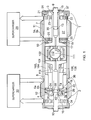
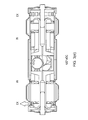
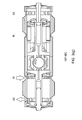
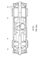
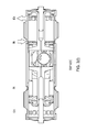
- the engine configuration of the present invention comprises a right cylinder 7, a left cylinder 8 and a single central crankshaft 112 located between the cylinders (for clarity, most of the supporting structure of the engine, apart from 1 and 2 has been omitted from FIGS. 1 and 2 ).
- the right cylinder 7 has an outer piston (P RO ) 3 and an inner piston (P RO ) 5 with combustion faces 23 and 25 respectively, the two pistons forming a combustion chamber 27 between them.
- the left cylinder 8 similarly has an outer piston 4 (P LO ) and an inner piston (P LI ) 6, with combustion faces 24 and 26 and combustion chamber 28.
- the two outer pistons 3 and 4 are rigidly connected together by the scotch yoke 101.
- the two upper, inner piston halves 5a and 6a are rigidly connected together by the upper scotch yoke 103 and the two lower, inner piston halves 5b and 6b are rigidly connected together by the lower scotch yoke 104.
- the two resulting inner piston/scotch yoke/piston halves whose split line is through the cylinders' axes and normal to the crankshaft's axis, are rigidly fastened together at the same time trapping the piston ring seal groups 17 and 18.
- the outer piston/scotch yoke/piston system 3, 101 and 4 is attached to the middle eccentric 115 of five eccentrics on the crankshaft 112 via a slipper 102.
- the inner piston/scotch yoke/piston system is attached to the inner pair of eccentrics 114 and 116 of the five eccentrics on the crankshaft 112 via slippers 105 and 106.
- the four pistons 3, 4, 5(a+b) and 6(a+b) are shown with a plurality of piston rings 19, 20, 21 and 22 respectively, located behind the combustion faces.
- additional piston rings may be employed further along the piston bodies or in the mating cylinder wall to minimize the escape of gases from the ports to the crankcase 118.
- additional piston rings are employed in the outer zones 31 and 32.
- the cylinders consist of sleeve valves 7 and 8 and their respective bearing caps 110 and 109, which are driven from the crankshaft by eccentrics 113 and 117 respectively.
- Sleeve valves 7 and 8 each have exhaust ports 35, 34 and intake ports 33 (intake ports of left-hand sleeve valve 8 not shown).
- the outer piston 3 On the right cylinder's sleeve valve 7, the outer piston 3 opens and closes exhaust ports 33 and the inner piston 5(a+b) opens and closes inlet ports 35.
- Multiple radial fuel injection ports 37 pierce the outer piston's tubular attachment and provide a path for fuel from the multiple radial fuel injection nozzles 39 of injector 9 to access the combustion chamber 27 only when the ports 37 register and envelop the nozzles 39 during the injection phase.
- the outer piston 4 opens and closes exhaust ports 34 and the inner piston 6(a+b) opens and closes inlet ports 36.
- Multiple radial fuel injection ports 38 pierce the outer piston's tubular attachment and provide a path for fuel from the multiple radial fuel injection nozzles 40 of injector 10 to access the combustion chamber 28 only when the ports 38 register and envelop the nozzles 40 during the injection phase (which, as shown in FIGS. 1 and 2 , is taking place in the left cylinder).
- Each of the five crankshaft eccentrics 113, 114, 115, 116 and 117 are uniquely positioned with respect to the crankshaft rotational axis 111.
- the eccentric for the outer exhaust pistons 115 and the coaxial eccentrics for the inner intake pistons 114 and 116 are at the same radial distance from the crankshaft rotational axis 111.
- the scotch yoke 101 is alternately received within the skirts of the inner intake pistons 5(a+b) and 6(a+b) and the radius of eccentric 115 is thereby restricted.
- the eccentric 115 for the outer exhaust pistons, which open and close the exhaust ports in the two cylinders, is angularly advanced in the preferred embodiment by 4°, while the coaxial eccentrics 114 and 116 for the inner intake pistons, which open and close the intake ports in the two cylinders, are angularly retarded by 4° (with respect to their theoretical 180° opposed positions in an engine embodiment with symmetrical port timing) and the coaxial eccentrics 113 and 117 which drive the cylinder sleeve valve motion are angularly retarded by (90+4)° with respect to the position of eccentric 115 (note that the direction of crankshaft rotation is counter-clockwise, as indicated by the arrows).
- the unique positions of the eccentrics contribute both to engine balance and to engine operation with respect to supercharging and recovering energy from the exhaust blowdown, as discussed below.
- the engine balance results in all non-rotational forces on the crankshaft cancelling, thus permitting a simplified crankshaft design, as also discussed below.
- the use of pistons opposed achieves a larger swept volume per cylinder while at the same time reducing the crankshaft throws, thereby reducing the engine height.
- the nested scotch yoke configuration allows for a very short, compact engine, while greatly reducing frictional losses from reaction forces through the piston/cylinder interfaces.
- the engine of the present invention provides substantial improvements in installation suitability, the reduction of friction losses and the elimination of vibration.
- the height of the opposed piston, opposed cylinder engine is determined primarily by the maximum sweep of the crankshaft and the minimum available clutch diameter and by flywheel requirements. With the piston-opposed design, the crankshaft throws may be cut roughly in half for the same cylinder displacement. A height reduced to approximately 200mm is therefore possible, compared to a height of 450mm for a 4-cylinder 4-stroke in-line engine.
- an engine embodying the present invention having a bore of 46.6mm would yield a swept volume of 158cm 3 .
- the single central crankshaft and nested scotch-yoke configuration permit a uniquely compact engine which, in a prototype design with a width of approximately 720mm, is within the available installation width for automobiles, commercial vehicles and light aircraft, etc. With a bore and stroke of 152 x 83.5mm, a swept volume of 5.5litres results. A mass of approximately 130kg with superchargers and accessories can be expected. Smaller versions would be required for most mass-production applications.
- a state-of-the-art 4-cylinder 4-stroke in-line engine has a crankshaft throw to connecting rod centres ratio ( ⁇ ) of about 0.25. Because of the scotch-yoke mechanisms, a ⁇ value of infinity is achieved and perfect Simple Harmonic Motion of all the pistons results.
- the 2-cylinder engine of the present invention has the same total number of pistons as a conventional 4-cylinder 4-stroke in-line engine, for a comparable power output, the mean piston velocity is substantially reduced since each piston travels a shorter distance.
- the piston-opposed configuration substantially eliminates the non-rotational combustion forces on the main bearings, since the pull from the outer piston counteracts the push from the inner piston. These large forces primarily stress the crankshaft in double shear and impose an almost pure torque on the crankshaft.
- the number of main bearings can therefore be reduced to two and the crankshaft and supporting engine structure may be made correspondingly lighter.
- the engine of the present invention can be totally dynamically balanced as discussed below even with substantial asymmetry in the exhaust and intake port timings. This is achieved through the use of the mass/eccentric throw products of the sleeve valves exactly counteracting the unbalanced component of the mass/eccentric throw products of the two piston/scotch-yoke/piston systems. Furthermore, the motion of the sleeve-valves modifies the exhaust and intake port timing in such a way that the port timing asymmetry can be at least three times the asymmetry of the crankshaft eccentrics.
- each cylinder of the engine has a separate supercharger 29 and 30.
- a supercharger may be economically dedicated to each cylinder, making more practical such techniques as pulse turbocharging.
- the superchargers are preferably electric motor assisted turbochargers, which serve to improve scavenging, improve engine performance at low engine speeds while avoiding turbo lag and recovering energy from the engine's exhaust (compounding) as described below as well as preheating the intake air for ease of cold starting.
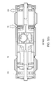
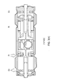
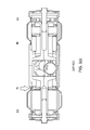
- FIGS. 3 illustrate the operation of the engine of the present invention over one complete crankshaft rotation.
- FIGS. 3(a) to 3(m) illustrate the piston positions, sleeve-valve and associated exhaust and intake port positions at 30° increments (note that crankshaft rotation in FIG. 3 is counter-clockwise as shown by the arrows).
- Crankshaft angle ⁇ is shown to the right of the FIG. number and labelled ADC (after dead centre) since the pistons in the left and right cylinders are simultaneously at IDC (inner dead centre) and ODC (outer dead centre) respectively.
- Arrows at the inlet ports IN and outlet ports EX indicate that the ports are open.
- FIG. 3(a) at 0° ADC shows the engine at a crankshaft position of 0° (arbitrarily defined as IDC in the left cylinder).
- the left outer piston P LO and the left inner piston P LI are at their point of closest approach.
- a fuel charge would be injected into the left cylinder and combustion would begin.
- the exhaust and intake ports (EX and IN) of the left cylinder are completely closed by P LO and P LI respectively.
- both pistons P LO and P LI have a slight velocity to the left, P LO having just changed direction.
- the right outer piston P RO and the right inner piston P RI are at their point of furthest separation.
- Both the exhaust and intake ports EX and IN of the right cylinder are open as shown by the arrows and the exhaust gases from the previous combustion cycle are being uniflow scavenged (flow in one direction rather than looping flow).
- both P RO and P RI must also have a slight velocity to the left since they are connected rigidly by nested scotch-yoke mechanisms, P RO having just changed direction.
- Both sleeve valves which move as one and lag the motion of pistons P LO and P RO by (90+4)° and lead the motion of pistons P LI and P RI by (90+4)°, are at mid-stroke with maximum velocity to the right thereby causing no effective change to the port timing.
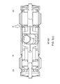
- pistons P LO and P LI of the left cylinder are moving apart at the beginning of the power stroke, PLI having changed its direction of travel.
- P LO since it leads P LI by 8°, is moving at a higher velocity than P LI .
- both sets of ports EX and IN remain open as shown by the arrows but ports EX are beginning to close.
- Both sleeve valves are 50% of their eccentrics' throw to the right of the mid-stroke position and still moving to the right thereby increasing the opening of the intake ports IN and reducing the opening of the exhaust ports EX in the right cylinder.
- piston P LO of the left cylinder has opened exhaust ports EX as shown by the arrow, while the intake ports remain closed.
- the turbocharger pulse turbocharging
- pistons P RO and P RI continue the compression stroke. Both sleeve valves are 87% of their eccentrics' throw to the right of the mid-stroke position and moving to the left thereby increasing the opening of the exhaust ports EX and have delayed the opening of the intake ports IN in the left cylinder.
- piston P LO of the left cylinder has opened the intake ports IN and the cylinder is being uniflow scavenged as shown by the arrows.
- the right cylinder is nearing the end of the compression stroke and the "squish" phase is beginning. This is where the outer, annular, opposite faces of pistons P RO and P RI begin to expel air from between them as shown by the arrows with dashed tails.
- Both sleeve valves are 50% of their eccentrics' throw to the right of the mid-stroke position and still moving to the left thereby increasing the opening of the exhaust ports EX and reducing the opening of the intake ports IN in the left cylinder.
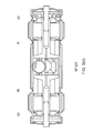
- pistons P LO and P LI of the left cylinder are causing both ports EX and IN to remain open as shown by the arrows and uniflow scavenging continues.
- the outer piston P LO has just changed its direction of travel.
- the right cylinder has reached the IDC position, where pistons P RO and P RI are at their position of closest approach, P RO having just changed direction.
- the "squish" phase continues as indicated by the arrows with dashed tails, causing an intensifying "smoke ring" effect to be superimposed on the already existing cylinder axis swirl caused by the partially tangential intake ports IN.
- both sets of ports EX and IN remain open as shown by the arrows but ports EX are beginning to close.
- Pistons P RO and P RI of the right cylinder are moving apart at the beginning of the power stroke, P RI having changed its direction of travel.
- P RO since it leads P RI by 8°, is moving at a higher velocity than P RI .
- Both sleeve valves are 50% of their eccentrics' throw to the left of the mid-stroke position and still moving to the left thereby increasing the opening of the intake ports IN and reducing the opening of the exhaust ports EX in the left cylinder.
- outer piston P LO has closed the exhaust ports EX, while the intake ports IN remain partially open to receive supercharge as shown by the arrow.
- the right cylinder continues its power stroke, with the two pistons P RO and P RI having more nearly equal but opposite velocities.
- Both sleeve valves are 87% of their eccentrics' throw to the left of the mid-stroke position and still moving to the left thereby increasing the opening of the intake ports IN and have hastened the closure of the exhaust ports EX in the left cylinder.
- FIG. 3(m) at 360° ADC the position is the same as in FIG. 3(a) .
- the left cylinder has reached the IDC position, where pistons P LO and P LI are at their position of closest approach, P LO having just changed direction.
- the "squish" phase continues as indicated by the arrows with dashed tails, causing an intensifying "smoke ring” effect to be superimposed on the already existing cylinder axis swirl caused by the partially tangential intake ports IN.
- These compound gas motions will be at their most intense at IDC when the combustion chamber most nearly resembles a toroid and is of minimum volume.
- Asymmetric timing of the exhaust and intake ports in a 2-stroke engine yields a number of important advantages. If the exhaust ports open before the intake ports, energy in the exhaust gases can be more effectively recovered by a turbocharger and if the exhaust ports close before the intake ports, the cylinder can be more effectively supercharged.
- the exhaust ports are controlled by the outer piston in each cylinder and the intake ports are controlled by the inner piston, as described above.
- This configuration not only allows for effective scavenging ("uniflow" scavenging) but also permits independent asymmetric timing of the exhaust and intake ports.
- Asymmetric timing of the two pistons in each cylinder is achieved by changing the relative angular positions of the corresponding crankshaft journals. Positioning the journals for the exhaust and intake pistons 180° apart would result in the both pistons reaching their maximum and minimum excursions at the same time (symmetric timing).
- the journals for the exhaust pistons are angularly advanced by 4° and the journals for the intake pistons are retarded by 4° (inner and outer dead centres thus still occur at the same crankshaft angle as in the symmetrically timed engine but both pistons have a small common velocity with respect to the cylinder).
- the mass/eccentric throw product of the sleeve valves can be matched in such a way as to completely eliminate the primary imbalance caused by the piston journals' asymmetry.
- This invention thus describes a 2-cylinder 2-stroke engine which can achieve perfect balance at primary and all higher orders. Furthermore, so long as the mass/eccentric throw products of the opposing piston/scotch yoke/piston systems remain equal, the exhaust and intake pistons' strokes may be different which allows optimisation of maximum available port areas for best performance.
- balance depends on having four, six, eight or more cylinders arranged such that the free-mass forces contributed by the individual pistons cancel. Counter-rotating weights are also often employed, adding complexity, mass and frictional loss to the engines.
- An advantage of the present invention is that total balance may be achieved in a compact engine with only two cylinders. Larger, multi-cylinder engines may then be made by placing multiple 2-cylinder engines side-by-side and coupling their crankshafts together. The coupling may be by such means as a clutch under operator or logic control, allowing pairs of cylinders to be uncoupled when not needed at low loads. Engines currently exist which use less than all of their cylinders when run at partial load but the cylinders remain connected to the crankshaft and the pistons continue to move within the cylinders and therefore continue to be a parasitic frictional load on the engine.
Landscapes
- Engineering & Computer Science (AREA)
- Mechanical Engineering (AREA)
- General Engineering & Computer Science (AREA)
- Chemical & Material Sciences (AREA)
- Combustion & Propulsion (AREA)
- Combustion Methods Of Internal-Combustion Engines (AREA)
- Cylinder Crankcases Of Internal Combustion Engines (AREA)
- Supercharger (AREA)
- Output Control And Ontrol Of Special Type Engine (AREA)
- Hydraulic Motors (AREA)
- Organic Low-Molecular-Weight Compounds And Preparation Thereof (AREA)
Applications Claiming Priority (2)
| Application Number | Priority Date | Filing Date | Title |
|---|---|---|---|
| GBGB0710852.5A GB0710852D0 (en) | 2007-06-06 | 2007-06-06 | Internal combustion engines |
| EP08750704.2A EP2171211B1 (en) | 2007-06-06 | 2008-05-28 | Internal combustion engines |
Related Parent Applications (2)
| Application Number | Title | Priority Date | Filing Date |
|---|---|---|---|
| EP08750704.2A Division EP2171211B1 (en) | 2007-06-06 | 2008-05-28 | Internal combustion engines |
| EP08750704.2A Division-Into EP2171211B1 (en) | 2007-06-06 | 2008-05-28 | Internal combustion engines |
Publications (1)
| Publication Number | Publication Date |
|---|---|
| EP3000965A1 true EP3000965A1 (en) | 2016-03-30 |
Family
ID=38318828
Family Applications (2)
| Application Number | Title | Priority Date | Filing Date |
|---|---|---|---|
| EP15186535.9A Withdrawn EP3000965A1 (en) | 2007-06-06 | 2008-05-28 | Internal combustion engines |
| EP08750704.2A Active EP2171211B1 (en) | 2007-06-06 | 2008-05-28 | Internal combustion engines |
Family Applications After (1)
| Application Number | Title | Priority Date | Filing Date |
|---|---|---|---|
| EP08750704.2A Active EP2171211B1 (en) | 2007-06-06 | 2008-05-28 | Internal combustion engines |
Country Status (16)
| Country | Link |
|---|---|
| US (1) | US8499726B2 (zh) |
| EP (2) | EP3000965A1 (zh) |
| JP (3) | JP2010529353A (zh) |
| KR (3) | KR20140002094A (zh) |
| CN (2) | CN101765699B (zh) |
| CY (1) | CY1117121T1 (zh) |
| DK (1) | DK2171211T3 (zh) |
| ES (1) | ES2556945T3 (zh) |
| GB (3) | GB0710852D0 (zh) |
| HK (1) | HK1175826A1 (zh) |
| HR (1) | HRP20160070T1 (zh) |
| HU (1) | HUE026639T2 (zh) |
| IL (1) | IL202491A (zh) |
| PT (1) | PT2171211E (zh) |
| SI (1) | SI2171211T1 (zh) |
| WO (1) | WO2008149061A2 (zh) |
Families Citing this family (27)
| Publication number | Priority date | Publication date | Assignee | Title |
|---|---|---|---|---|
| GB2477272B (en) | 2010-01-27 | 2014-06-25 | Two Stroke Developments Ltd | Internal combustion engine comprising piston dwell mechanism |
| DE102010038543A1 (de) * | 2010-07-28 | 2012-02-02 | Robert Bosch Gmbh | Über einen Dampfkraftprozess antreibbare Kolbenmaschine |
| US8763583B2 (en) * | 2011-02-11 | 2014-07-01 | Ecomotors, Inc. | Opposed-piston, opposed-cylinder engine with collinear cylinders |
| GB2494371B (en) | 2011-05-24 | 2013-12-04 | Cox Powertrain Ltd | Internal combustion engine with an opposed piston configuration |
| GB2491155B (en) | 2011-05-24 | 2013-04-10 | Cox Powertrain Ltd | Opposed piston engine having injector located within cylinder |
| GB2493061A (en) * | 2011-07-15 | 2013-01-23 | Ecomotors Internat Inc | Opposed piston engine with toroidal combustion chamber |
| GB2495827A (en) * | 2011-10-20 | 2013-04-24 | Ecomotors Internat Inc | Balancing an Opposed-Piston, Opposed-Cylinder Engine |
| GB201122432D0 (en) | 2011-12-23 | 2012-02-08 | Cox Powertrain Ltd | Internal combustion engines |
| US8925528B2 (en) * | 2012-06-26 | 2015-01-06 | Ford Global Technologies, Llc | Engine balancing supercharger |
| CA2906193A1 (en) * | 2013-03-15 | 2014-09-18 | Prime Group Alliance, Llc | Opposed piston internal combustion engine with inviscid layer sealing |
| DE102013106755A1 (de) * | 2013-06-27 | 2014-12-31 | Bertwin R. Geist | Gleitstein für eine Kurbelschlaufen-Hubkolbenmaschine |
| CN103670698A (zh) * | 2013-09-09 | 2014-03-26 | 安徽中鼎动力有限公司 | 一种发动机机体 |
| EP3068973A1 (en) | 2013-10-17 | 2016-09-21 | Cox Powertrain Ltd | Internal combustion engines |
| US9032927B1 (en) * | 2013-11-08 | 2015-05-19 | Achates Power, Inc. | Cold-start strategies for opposed-piston engines |
| CN104564331A (zh) * | 2015-01-28 | 2015-04-29 | 邵金彪 | 一种串联活塞的往复式同步冲程内燃机 |
| US9447754B1 (en) | 2015-07-02 | 2016-09-20 | Bright Acceleration Technologies LLC | Method and apparatus for internal combustion engine system with improved turbocharging |
| CN105804869A (zh) * | 2016-03-15 | 2016-07-27 | 刘运金 | 一种双轴活塞发动机 |
| US10082099B2 (en) | 2016-08-09 | 2018-09-25 | Achates Power, Inc. | Port edge shape with continuous curvature for improved ring-port interaction and flow area |
| US10215129B2 (en) * | 2016-08-09 | 2019-02-26 | Achates Power, Inc. | Port edge shape with continuous curvature for improved ring-port interaction and flow area |
| US9638095B1 (en) | 2016-09-01 | 2017-05-02 | Bright Acceleration Technologies LLC | Synergistic induction and turbocharging in internal combustion engine systems |
| US10107215B2 (en) | 2016-09-01 | 2018-10-23 | Bright Acceleration Technologies LLC | Synergistic induction and turbocharging in internal combustion engine systems |
| US10697357B2 (en) | 2016-09-01 | 2020-06-30 | Bright Acceleration Technologies LLC | Cross-port air flow to reduce pumping losses |
| US10364739B2 (en) | 2016-09-01 | 2019-07-30 | Bright Acceleration Technologies LLC | Synergistic induction and turbocharging in internal combustion engine systems |
| CN106523131B (zh) * | 2016-11-10 | 2018-12-18 | 宁波市鄞州煜隆工具有限公司 | 一种二冲程内燃机 |
| WO2018167474A1 (en) * | 2017-03-13 | 2018-09-20 | Enhanced Energy Efficiency Enterprises Limited | Internal combustion engine |
| GB201719042D0 (en) * | 2017-11-17 | 2018-01-03 | Oxford Two Stroke Ltd | Internal combustion engine |
| CN110185539B (zh) * | 2019-07-01 | 2024-03-01 | 西北农林科技大学 | 一种双缸内燃机 |
Citations (3)
| Publication number | Priority date | Publication date | Assignee | Title |
|---|---|---|---|---|
| DE19503442C1 (de) * | 1995-02-03 | 1996-05-23 | Daimler Benz Ag | Zweitakt-Gegenkolbenmotor |
| US6170443B1 (en) | 1998-09-11 | 2001-01-09 | Edward Mayer Halimi | Internal combustion engine with a single crankshaft and having opposed cylinders with opposed pistons |
| FR2888907A1 (fr) * | 2005-07-21 | 2007-01-26 | Marie Therese Mazille | Dispositif pour ouvrir et fermer les lumieres de distribution dans les moteurs deux temps, et guider les pistons quand ils sont monocylindriques. |
Family Cites Families (18)
| Publication number | Priority date | Publication date | Assignee | Title |
|---|---|---|---|---|
| US1257104A (en) * | 1916-05-26 | 1918-02-19 | Oscar A Olson | Internal-combustion engine. |
| US2093433A (en) * | 1933-06-09 | 1937-09-21 | Greene Catharine De Motte | Internal combustion engine |
| US2132802A (en) * | 1937-07-21 | 1938-10-11 | Jefferson F Pierce | Internal combustion engine |
| US2169807A (en) * | 1938-03-04 | 1939-08-15 | George R Lyon | Compressor |
| US2213817A (en) * | 1939-04-03 | 1940-09-03 | Walter T Kinslow | Internal expansion engine |
| GB690479A (en) | 1947-12-19 | 1953-04-22 | Frederick Charles Hammick | Improvements in or relating to internal combustion engines having two pistons acted upon by the same impulse |
| DE2744686A1 (de) * | 1977-09-30 | 1979-04-05 | Hermann Prof Dipl Ing Schott | Gegenkolben-motor/aufbau |
| AU4236593A (en) * | 1992-05-06 | 1993-11-29 | Balanced Engines, Inc. | Balanced compound engine |
| DE19503443C1 (de) | 1995-02-03 | 1996-05-15 | Daimler Benz Ag | Zweitakt-Gegenkolbenmotor |
| JP3698858B2 (ja) | 1997-06-10 | 2005-09-21 | リンナイ株式会社 | ガス遮断弁 |
| US6065440A (en) * | 1999-07-07 | 2000-05-23 | Pasquan; Raymond F. | Internal combustion engine with binary cylinder sizing for variable power output |
| JP2001355451A (ja) * | 2000-06-14 | 2001-12-26 | Walbro Japan Inc | 層状掃気2行程内燃機関 |
| UA61980C2 (en) * | 2000-06-15 | 2003-12-15 | Ihor Olehovych Kyryliuk | Opposite internal combustion engine |
| US6536399B2 (en) * | 2000-11-15 | 2003-03-25 | Honda Giken Kogyo Kabushiki Kaisha | Crankshaft supporting structure for horizontal opposed type internal combustion engine |
| BG105831A (bg) * | 2001-08-20 | 2003-02-28 | Стоян КОКУДЕВ | Комбиниран бутален двигател |
| US7004120B2 (en) * | 2003-05-09 | 2006-02-28 | Warren James C | Opposed piston engine |
| JP2006002803A (ja) | 2004-06-15 | 2006-01-05 | Toyo Tire & Rubber Co Ltd | サスペンションサポート |
| GB2432398B (en) | 2005-11-18 | 2008-08-13 | Lotus Car | Reciprocating piston sleeve valve engine |
-
2007
- 2007-06-06 GB GBGB0710852.5A patent/GB0710852D0/en not_active Ceased
-
2008
- 2008-05-28 CN CN2008800230222A patent/CN101765699B/zh not_active Expired - Fee Related
- 2008-05-28 HU HUE08750704A patent/HUE026639T2/en unknown
- 2008-05-28 GB GB1215622.0A patent/GB2491297B/en not_active Expired - Fee Related
- 2008-05-28 JP JP2010510866A patent/JP2010529353A/ja active Pending
- 2008-05-28 EP EP15186535.9A patent/EP3000965A1/en not_active Withdrawn
- 2008-05-28 KR KR1020137033176A patent/KR20140002094A/ko active IP Right Grant
- 2008-05-28 CN CN201310479173.1A patent/CN103511079B/zh not_active Expired - Fee Related
- 2008-05-28 EP EP08750704.2A patent/EP2171211B1/en active Active
- 2008-05-28 SI SI200831568T patent/SI2171211T1/sl unknown
- 2008-05-28 GB GB0922628.3A patent/GB2463204B/en not_active Expired - Fee Related
- 2008-05-28 US US12/663,519 patent/US8499726B2/en active Active
- 2008-05-28 ES ES08750704.2T patent/ES2556945T3/es active Active
- 2008-05-28 WO PCT/GB2008/001798 patent/WO2008149061A2/en active Application Filing
- 2008-05-28 KR KR1020157006189A patent/KR101738791B1/ko active IP Right Grant
- 2008-05-28 KR KR1020107000123A patent/KR101458247B1/ko active IP Right Grant
- 2008-05-28 DK DK08750704.2T patent/DK2171211T3/en active
- 2008-05-28 PT PT87507042T patent/PT2171211E/pt unknown
-
2009
- 2009-12-03 IL IL202491A patent/IL202491A/en active IP Right Grant
-
2012
- 2012-04-26 JP JP2012100894A patent/JP5662374B2/ja not_active Expired - Fee Related
- 2012-04-26 JP JP2012100895A patent/JP5690772B2/ja not_active Expired - Fee Related
-
2013
- 2013-03-07 HK HK13102830.5A patent/HK1175826A1/xx not_active IP Right Cessation
-
2016
- 2016-01-11 CY CY20161100017T patent/CY1117121T1/el unknown
- 2016-01-22 HR HRP20160070TT patent/HRP20160070T1/hr unknown
Patent Citations (3)
| Publication number | Priority date | Publication date | Assignee | Title |
|---|---|---|---|---|
| DE19503442C1 (de) * | 1995-02-03 | 1996-05-23 | Daimler Benz Ag | Zweitakt-Gegenkolbenmotor |
| US6170443B1 (en) | 1998-09-11 | 2001-01-09 | Edward Mayer Halimi | Internal combustion engine with a single crankshaft and having opposed cylinders with opposed pistons |
| FR2888907A1 (fr) * | 2005-07-21 | 2007-01-26 | Marie Therese Mazille | Dispositif pour ouvrir et fermer les lumieres de distribution dans les moteurs deux temps, et guider les pistons quand ils sont monocylindriques. |
Also Published As
Similar Documents
| Publication | Publication Date | Title |
|---|---|---|
| EP2171211B1 (en) | Internal combustion engines | |
| EP1866530B1 (en) | Double piston cycle engine | |
| US9512777B2 (en) | Internal combustion engines | |
| JP3859595B2 (ja) | シングルクランクシャフトを備え、対向するピストンを持つ対向するシリンダを有する内燃機関 | |
| US20140196693A1 (en) | Internal combustion engines | |
| AU2013350310B2 (en) | Internal combustion engine with asymmetric port timing | |
| EP2805016B1 (en) | Internal combustion engines |
Legal Events
| Date | Code | Title | Description |
|---|---|---|---|
| PUAI | Public reference made under article 153(3) epc to a published international application that has entered the european phase |
Free format text: ORIGINAL CODE: 0009012 |
|
| AC | Divisional application: reference to earlier application |
Ref document number: 2171211 Country of ref document: EP Kind code of ref document: P |
|
| AK | Designated contracting states |
Kind code of ref document: A1 Designated state(s): AT BE BG CH CY CZ DE DK EE ES FI FR GB GR HR HU IE IS IT LI LT LU LV MC MT NL NO PL PT RO SE SI SK TR |
|
| 17P | Request for examination filed |
Effective date: 20160929 |
|
| RBV | Designated contracting states (corrected) |
Designated state(s): AT BE BG CH CY CZ DE DK EE ES FI FR GB GR HR HU IE IS IT LI LT LU LV MC MT NL NO PL PT RO SE SI SK TR |
|
| RIC1 | Information provided on ipc code assigned before grant |
Ipc: F02F 1/22 20060101ALN20170313BHEP Ipc: F02B 75/24 20060101ALI20170313BHEP Ipc: F01B 9/02 20060101ALI20170313BHEP Ipc: F01B 7/10 20060101ALN20170313BHEP Ipc: F02B 75/02 20060101ALN20170313BHEP Ipc: F02B 25/08 20060101ALI20170313BHEP Ipc: F01B 7/04 20060101ALI20170313BHEP Ipc: F02F 3/00 20060101ALN20170313BHEP Ipc: F02B 75/28 20060101ALI20170313BHEP Ipc: F02B 75/18 20060101ALN20170313BHEP Ipc: F02M 61/14 20060101ALI20170313BHEP Ipc: F16H 21/36 20060101ALI20170313BHEP Ipc: F01B 1/08 20060101AFI20170313BHEP |
|
| GRAP | Despatch of communication of intention to grant a patent |
Free format text: ORIGINAL CODE: EPIDOSNIGR1 |
|
| RIC1 | Information provided on ipc code assigned before grant |
Ipc: F02B 75/18 20060101ALN20170323BHEP Ipc: F16H 21/36 20060101ALI20170323BHEP Ipc: F02B 75/24 20060101ALI20170323BHEP Ipc: F02B 75/28 20060101ALI20170323BHEP Ipc: F01B 1/08 20060101AFI20170323BHEP Ipc: F01B 7/04 20060101ALI20170323BHEP Ipc: F02F 1/22 20060101ALN20170323BHEP Ipc: F02B 25/08 20060101ALI20170323BHEP Ipc: F02F 3/00 20060101ALN20170323BHEP Ipc: F01B 7/10 20060101ALN20170323BHEP Ipc: F02M 61/14 20060101ALI20170323BHEP Ipc: F01B 9/02 20060101ALI20170323BHEP Ipc: F02B 75/02 20060101ALN20170323BHEP |
|
| INTG | Intention to grant announced |
Effective date: 20170421 |
|
| STAA | Information on the status of an ep patent application or granted ep patent |
Free format text: STATUS: THE APPLICATION IS DEEMED TO BE WITHDRAWN |
|
| 18D | Application deemed to be withdrawn |
Effective date: 20170902 |