EP3000700A1 - Système de projecteurs et véhicule à selle - Google Patents
Système de projecteurs et véhicule à selle Download PDFInfo
- Publication number
- EP3000700A1 EP3000700A1 EP15181772.3A EP15181772A EP3000700A1 EP 3000700 A1 EP3000700 A1 EP 3000700A1 EP 15181772 A EP15181772 A EP 15181772A EP 3000700 A1 EP3000700 A1 EP 3000700A1
- Authority
- EP
- European Patent Office
- Prior art keywords
- illumination range
- sub
- light
- head lamp
- cut
- Prior art date
- Legal status (The legal status is an assumption and is not a legal conclusion. Google has not performed a legal analysis and makes no representation as to the accuracy of the status listed.)
- Granted
Links
- 238000005286 illumination Methods 0.000 claims abstract description 390
- 239000013589 supplement Substances 0.000 claims description 3
- 238000000034 method Methods 0.000 description 22
- 238000010586 diagram Methods 0.000 description 19
- 230000012447 hatching Effects 0.000 description 17
- 238000001514 detection method Methods 0.000 description 6
- 239000000470 constituent Substances 0.000 description 2
- 230000004313 glare Effects 0.000 description 2
- 230000000694 effects Effects 0.000 description 1
- 230000006870 function Effects 0.000 description 1
- 230000002401 inhibitory effect Effects 0.000 description 1
Images


Classifications
-
- B—PERFORMING OPERATIONS; TRANSPORTING
- B60—VEHICLES IN GENERAL
- B60Q—ARRANGEMENT OF SIGNALLING OR LIGHTING DEVICES, THE MOUNTING OR SUPPORTING THEREOF OR CIRCUITS THEREFOR, FOR VEHICLES IN GENERAL
- B60Q1/00—Arrangement of optical signalling or lighting devices, the mounting or supporting thereof or circuits therefor
- B60Q1/02—Arrangement of optical signalling or lighting devices, the mounting or supporting thereof or circuits therefor the devices being primarily intended to illuminate the way ahead or to illuminate other areas of way or environments
- B60Q1/04—Arrangement of optical signalling or lighting devices, the mounting or supporting thereof or circuits therefor the devices being primarily intended to illuminate the way ahead or to illuminate other areas of way or environments the devices being headlights
- B60Q1/06—Arrangement of optical signalling or lighting devices, the mounting or supporting thereof or circuits therefor the devices being primarily intended to illuminate the way ahead or to illuminate other areas of way or environments the devices being headlights adjustable, e.g. remotely-controlled from inside vehicle
- B60Q1/08—Arrangement of optical signalling or lighting devices, the mounting or supporting thereof or circuits therefor the devices being primarily intended to illuminate the way ahead or to illuminate other areas of way or environments the devices being headlights adjustable, e.g. remotely-controlled from inside vehicle automatically
- B60Q1/12—Arrangement of optical signalling or lighting devices, the mounting or supporting thereof or circuits therefor the devices being primarily intended to illuminate the way ahead or to illuminate other areas of way or environments the devices being headlights adjustable, e.g. remotely-controlled from inside vehicle automatically due to steering position
-
- B—PERFORMING OPERATIONS; TRANSPORTING
- B60—VEHICLES IN GENERAL
- B60Q—ARRANGEMENT OF SIGNALLING OR LIGHTING DEVICES, THE MOUNTING OR SUPPORTING THEREOF OR CIRCUITS THEREFOR, FOR VEHICLES IN GENERAL
- B60Q1/00—Arrangement of optical signalling or lighting devices, the mounting or supporting thereof or circuits therefor
- B60Q1/02—Arrangement of optical signalling or lighting devices, the mounting or supporting thereof or circuits therefor the devices being primarily intended to illuminate the way ahead or to illuminate other areas of way or environments
- B60Q1/04—Arrangement of optical signalling or lighting devices, the mounting or supporting thereof or circuits therefor the devices being primarily intended to illuminate the way ahead or to illuminate other areas of way or environments the devices being headlights
- B60Q1/14—Arrangement of optical signalling or lighting devices, the mounting or supporting thereof or circuits therefor the devices being primarily intended to illuminate the way ahead or to illuminate other areas of way or environments the devices being headlights having dimming means
- B60Q1/1415—Dimming circuits
- B60Q1/1423—Automatic dimming circuits, i.e. switching between high beam and low beam due to change of ambient light or light level in road traffic
-
- B—PERFORMING OPERATIONS; TRANSPORTING
- B62—LAND VEHICLES FOR TRAVELLING OTHERWISE THAN ON RAILS
- B62J—CYCLE SADDLES OR SEATS; AUXILIARY DEVICES OR ACCESSORIES SPECIALLY ADAPTED TO CYCLES AND NOT OTHERWISE PROVIDED FOR, e.g. ARTICLE CARRIERS OR CYCLE PROTECTORS
- B62J6/00—Arrangement of optical signalling or lighting devices on cycles; Mounting or supporting thereof; Circuits therefor
- B62J6/02—Headlights
- B62J6/022—Headlights specially adapted for motorcycles or the like
- B62J6/023—Headlights specially adapted for motorcycles or the like responsive to the lean angle of the cycle, e.g. changing intensity or switching sub-lights when cornering
-
- B—PERFORMING OPERATIONS; TRANSPORTING
- B62—LAND VEHICLES FOR TRAVELLING OTHERWISE THAN ON RAILS
- B62J—CYCLE SADDLES OR SEATS; AUXILIARY DEVICES OR ACCESSORIES SPECIALLY ADAPTED TO CYCLES AND NOT OTHERWISE PROVIDED FOR, e.g. ARTICLE CARRIERS OR CYCLE PROTECTORS
- B62J6/00—Arrangement of optical signalling or lighting devices on cycles; Mounting or supporting thereof; Circuits therefor
- B62J6/02—Headlights
- B62J6/022—Headlights specially adapted for motorcycles or the like
- B62J6/024—Switching between high and low beam
-
- B—PERFORMING OPERATIONS; TRANSPORTING
- B60—VEHICLES IN GENERAL
- B60Q—ARRANGEMENT OF SIGNALLING OR LIGHTING DEVICES, THE MOUNTING OR SUPPORTING THEREOF OR CIRCUITS THEREFOR, FOR VEHICLES IN GENERAL
- B60Q2300/00—Indexing codes for automatically adjustable headlamps or automatically dimmable headlamps
- B60Q2300/10—Indexing codes relating to particular vehicle conditions
- B60Q2300/13—Attitude of the vehicle body
- B60Q2300/136—Roll
Definitions
- the present invention relates to a head lamp system and a straddled vehicle.
- a head lamp system having a plurality of head lamps is provided in order to improve visibility of an area in front of the vehicle.
- JP 2008-222178 A a headlight for the motorcycle constituted by a plurality of lighting tool units are described.
- a low beam mode a plurality of low beam lighting tool units light up.
- a high beam mode a plurality of high beam lighting tool units light up.
- part of the plurality of high beam lighting tool units lights up in a reduced-light state in addition to the plurality of low beam lighting tool units.
- JP 2013-193561 A a motorcycle in which low beam head lamps, high beam head lamps and sub-lamps are provided is described.
- the plurality of sub-lamps light up according to a bank angle of a vehicle body of the motorcycle under a condition in which the low beam head lamps are lit up.
- JP 2008-222178 A the vehicle body banks in the left-and-right direction at a time of cornering of the vehicle, so that illumination ranges of the plurality of low beam lighting tool units change. Therefore, in the low beam mode, when the vehicle body of the motorcycle banks in the left-and-right direction, part of the plurality of high beam lighting tool units lights up in the reduced-light state in addition to the plurality of low beam lighting tool units. Thus, light distribution in which the illumination ranges of the plurality of low beam lighting tool units are supplemented is acquired.
- JP 2013-193561 A a head lamp system having a plurality of head lamps and a plurality of auxiliary sub-lamps is provided in the straddled vehicle, so that the light distribution in which the illumination ranges reduced due to the bank of the vehicle at the time of cornering of the vehicle are supplemented is acquired.
- An object of the present invention is to provide a head lamp system that can acquire preferable light distribution during an operation in a low beam mode and during an operation in a high beam mode while an increase in size is inhibited, and a straddled vehicle including the head lamp system.
- the first main illumination range is irradiated with light by the head lamp unit and the second main illumination range except for the first main illumination range is not irradiated with light.
- the first auxiliary illumination area is irradiated with light by the first sub-lamp.
- an area ahead of the vehicle on the left is brightly illuminated at the time of cornering leftward of the vehicle.
- the second auxiliary illumination range is irradiated with light by the second sub-lamp.
- an area ahead of the vehicle on the right is brightly illuminated at the time of cornering rightward of the vehicle.
- the second main illumination range is irradiated with light by the head lamp unit.
- the light from the head lamp unit is concentrated in a relatively narrow range. Therefore, the light can reach a far distance without an increase in size of the head lamp unit.
- the first and second auxiliary illumination ranges are irradiated with light at all times by the first and second sub-lamps.
- the high beam light distribution that is expanded to the left and right is acquired by the second main illumination range and the first and second auxiliary illumination ranges.
- a rider easily confirms the conditions of the left and right of the vehicle when the vehicle is travelling in a straight line, and easily confirms the condition of the road surface before the vehicle enters a curve. It is not necessary to increase the size of the head lamp unit or provide another sub-lamp in order to acquire the high beam light distribution that is expanded to the left and right.
- the operation of the head lamp unit can be easily switched between the low beam mode and the high beam mode.
- an area ahead of the vehicle on the left is more brightly illuminated at the time of cornering leftward of the vehicle
- an area ahead of the vehicle on the right is more brightly illuminated at the time of cornering rightward of the vehicle without an excessive increase in brightness of the area front ahead of the vehicle.
- areas even farther left and right of the vehicle are brightly illuminated without an excessive increase in brightness in the area front ahead of the vehicle.
- the bank angle of the vehicle of when the third sub-lamp lights up during the operation in the low beam mode and the bank angle of the vehicle of when the third sub-lamp lights up during the operation in the high beam mode are equal to each other.
- the bank angle of the vehicle of when the fourth sub-lamp lights up during the operation in the low beam mode and the bank angle of the vehicle of when the fourth sub-lamp lights up during the operation in the high beam mode are equal to each other.
- this configuration causes the area ahead of the vehicle on the left to be more brightly illuminated. Further, during the operation in the low beam mode or during the operation in the high beam mode, even when the vehicle largely banks rightward at the time of cornering rightward, the area ahead of the vehicle on the right is more brightly illuminated. Thus, even when the bank angle of the vehicle at the time of cornering of the vehicle is large, more preferable light distribution can be realized.
- the bank angle of the vehicle of when the fifth sub-lamp lights up during the operation in the low beam mode and the bank angle of the vehicle of when the fifth sub-lamp lights up during the operation in the high beam mode are equal to each other.
- the bank angle of the vehicle of when the sixth sub-lamp lights up during the operation in the low beam mode and the bank angle of the vehicle of when the sixth sub-lamp lights up during the operation in the high beam mode are equal to each other.
- this configuration causes the area ahead of the vehicle on the left to be more brightly illuminated. Further, during the operation in the low beam mode or during the operation in the high beam mode, even when the vehicle more largely banks rightward at the time of cornering rightward, the area ahead of the vehicle on the right is more brightly illuminated. Thus, even when the bank angle of the vehicle at the time of cornering of the vehicle is larger, more preferable light distribution can be realized.
- the bank angle of the vehicle body is detected by the detector.
- the first main illumination range is irradiated with light by the head lamp unit, and the second main illumination range except for the first main illumination range is not irradiated with light.
- the first auxiliary illumination range is irradiated with light by the first sub-lamp.
- the second auxiliary illumination range is irradiated with light by the second sub-lamp.
- the area ahead of the vehicle on the right is brightly illuminated.
- the second main illumination range is irradiated with light by the head lamp unit.
- the light from the head lamp unit is concentrated in a relatively narrow range. Therefore, the light can reach a far distance without an increase in size of the head lamp unit.
- the first and second auxiliary illumination ranges are irradiated with light at all times by the first and second sub-lamps. In this case, the high beam light distribution that is expanded to the left and right is acquired by the second main illumination range, and the first and second auxiliary illumination ranges.
- the area farther front ahead and the areas farther left and right of the vehicle can be brightly illuminated when the vehicle is traveling in a straight line and before the vehicle enters a curve. Therefore, the rider easily confirms the conditions of the left and right of the vehicle when the vehicle is travelling in a straight line, and easily confirms the condition of the road surface before the vehicle enters a curve. It is not necessary to increase the size of the head lamp unit or provide another sub-lamp in order to acquire the high beam light distribution that is expanded to the left and right.
- the straddled vehicle according to one embodiment of the present invention will be described below with reference to drawings.
- a motorcycle is described as one example of the straddled vehicle.
- the straddled vehicle according to the present embodiment is a vehicle in which a vehicle body banks leftward at a time of cornering leftward of the vehicle and banks rightward at a time of cornering rightward of the vehicle.
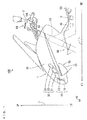
- Fig. 1 is an enlarged side view of the left side of part of the motorcycle according to one embodiment of the present invention.
- Fig. 2 is an enlarged front view showing part of the motorcycle 100 of Fig. 1 .
- the motorcycle 100 standing up to be perpendicular to a road surface is shown.
- a front-and-rear direction L, a left-and-right direction W and a top-and-bottom direction H of the motorcycle 100 are indicated by arrows.
- a direction in which an arrow is directed in the front-and-rear direction L is referred to as forward, and its opposite direction is referred to as rearward.
- a direction in which an arrow is directed in the right-and-left direction W is referred to as leftward, and its opposite direction is referred to as rightward.
- a direction in which an arrow is directed in the top-and-bottom direction H is referred to as upward, and its opposite direction is referred to as downward.
- forward, rearward, leftward, rightward, upward and downward are respectively indicated by reference numerals FO, RE, LE, RI, UP, LO. These directions are defined based on a direction in which a rider is facing on the motorcycle.
- the motorcycle 100 includes a vehicle body frame 50 that extends in the front-and-rear direction L.
- a front portion of the vehicle body frame 50 is bent upward and forward.
- the vehicle body frame 50 includes a head pipe 51 that extends downward and forward in the front portion.
- a front fork device 60 is attached to the head pipe 51 to be rotatable in the left and right direction.
- the front fork device 60 includes a steering shaft (a stem shaft) 61, a left fork pipe 62, a right fork pipe 63, a handle member 64, and a front wheel that is not shown.
- the steering shaft 61 is inserted into the head pipe 51 to extend downward and forward.
- the left fork pipe 62 and the right fork pipe 63 are respectively arranged at the left and right of the steering shaft 61.
- the left fork pipe 62 and the right fork pipe 63 are connected to the steering shaft 61 by a plurality of connection members (an under bracket and an upper bracket) that are not shown.
- a front wheel (not shown) is rotatably supported between a lower portion of the left fork pipe 62 and a lower portion of the right fork pipe 63.
- the handle member 64 includes a left handle 64L and a right handle 64R. The handle member 64 is connected to the left fork pipe 62 and the right fork pipe 63. The handle member 64 is operated, so that the front fork device 60 is rotated with respect to the head pipe 51.
- a cowl 70 is provided to cover the head pipe 51 from the front and to cover part of the left fork pipe 62 and the right fork pipe 63 from both sides.
- the cowl 70 is attached to the vehicle body frame 50.
- a head lamp unit 10, a sub-lamp unit 20 and a turn indicator lamp unit 30 are attached to the cowl 70.
- the head lamp unit 10 includes two head lamps 11, 12 operable in a low beam mode and a high beam mode.
- the low beam mode and the high beam mode will be described below.
- Each of the head lamps 11, 12 has one or plurality of light sources.
- the light source may be a light bulb, a light-emitting diode or another light emitter.
- the head lamps 11, 12 are arranged at the center of the cowl 70 in the left-and-right direction W.
- the head lamp 12 is arranged above the head lamp 11. In the left-and-right direction W, the width of the head lamp 12 is smaller than the width of the head lamp 11. In the left-and-right direction W, the center of each of the head lamps 11, 12 is located at the center of the cowl 70.
- the sub-lamp unit 20 includes a plurality (six in the present example) of sub-lamps 21, 22, 23, 24, 25, 26 that supplement light distribution of the head lamp unit 10.
- Each of the sub-lamps 21 to 26 includes one or plurality of light sources.
- the light source may be a light bulb, a light-emitting diode or another light emitter.
- the sub-lamps 21, 23, 25 are arranged at the left of the head lamp unit 10, and the sub-lamps 22, 24, 26 are arranged at the right of the head lamp unit 10.
- the sub-lamps 21, 23, 25 are arranged to be laterally symmetric with the sub-lamps 22, 24, 26 with respect to the head lamp unit 10.
- the sub-lamp 23 is arranged at the upper left of the sub-lamp 21 to be adjacent to the sub-lamp 21, and the sub-lamp 25 is arranged at the upper left of the sub-lamp 23 to be adjacent to the sub-lamp 23.
- the sub-lamp 24 is arranged at the upper right of the sub-lamp 22 to be adjacent to the sub-lamp 22, and the sub-lamp 26 is arranged at the upper right of the sub-lamp 24 to be adjacent to the sub-lamp 24.
- the sub-lamp 21 is arranged at the upper back of the head lamp unit 10
- the sub-lamp 23 is arranged at the upper back of the sub-lamp 21
- the sub-lamp 25 is arranged at the upper back of the sub-lamp 23.
- the sub-lamp 22 is arranged at the upper back of the head lamp unit 10
- the sub-lamp 24 is arranged at the upper back of the sub-lamp 22
- the sub-lamp 26 is arranged at the upper back of the sub-lamp 24.
- the turn indicator lamp unit 30 is constituted by two turn indicator lamps 31, 32.
- the turn indicator lamp 31 is arranged at a position further leftward than the center of the cowl 70 in the left-and-right direction W
- the turn indicator lamp 32 is arranged at a position further rightward than the center of the cowl 70 in the left-and-right direction W.
- the turn indicator lamp 31 is arranged below the sub-lamps 23, 25, and the turn indicator lamp 32 is arranged below the sub-lamps 24, 26.
- a controller 40 is provided at the vehicle body frame 50.
- the controller 40 is an ECU (Electronic Control Unit), for example.
- the controller 40 may be a microcomputer.
- a head lamp system 1 is constituted by the head lamp unit 10, the sub-lamp unit 20 and the controller 40. An operation of the head lamp system 1 and illumination ranges by the head lamp unit 10 and the sub-lamp unit 20 will be described below.
- a detector 2 is provided at the vehicle body frame 50.
- the detector 2 includes a tilt detection sensor and a calculator.
- the tilt detection sensor is a three-axis angular velocity sensor (a three axis gyroscope), for example.
- the tilt detection sensor may be an angular velocity sensor, or another type of tilt detection sensor, for example.
- the tilt detection sensor detects a bank angle of the vehicle body frame 50 with respect to a vertical direction.
- the calculator calculates (estimates) the bank angle detected by the tilt detection sensor.
- the calculator supplies the calculated bank angle to the controller 40.
- an operation unit 3 is provided near the left handle 64L in the handle member 64.
- the operation unit 3 includes a switch for designating an operation mode of the head lamp unit 10. The rider can switch the operation mode of the head lamp unit 10 between the low beam mode and the high beam mode by operating the operation unit 3.
- the operation unit 3 includes a switch for operating the turn indicator lamp unit 30.
- the rider operates the operation unit 3 when indicating the direction of turning, for example.
- the controller 40 controls the turn indicator lamp unit 30 based on a state of the switch of the operation unit 3.
- the turn indicator lamp 31 or the turn indicator lamp 32 lights up.
- Fig. 3 is a diagram for explaining the illumination ranges.
- a virtual screen SC vertically standing up at a position in front of and spaced apart by a constant distance D from the motorcycle 100 to face the motorcycle 100 is defined.
- the distance D is set to a distance by which the motorcycle 100 that travels at a predetermined speed is moved in a predetermined time period of "t" seconds, for example. That is, when the rider confirms an obstacle standing still at the position of the screen SC from the motorcycle 100, the motorcycle 100 reaches the position of the obstacle in the time period of "t" seconds. Therefore, the rider can perform the operation of the motorcycle 100 in order to avoid collision with the obstacle in the time period of "t" seconds.
- a plurality of illumination ranges are defined on the screen SC.
- the plurality of illumination ranges on the screen SC are irradiated with light from the head lamps 11, 12 and the sub-lamps 21 to 26 of the head lamp system 1.
- the plurality of illumination ranges defined on the screen SC will be described below.
- the illumination ranges defined below are the illumination ranges corresponding to the motorcycle 100 vertically standing up. When the motorcycle 100 banks leftward or rightward, the illumination ranges tilt leftward or rightward in correspondence with the bank angle of the motorcycle 100.
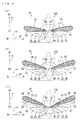
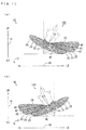
- Figs. 4(a), 4(b) are diagrams showing the illumination ranges defined on the screen SC.
- contours of the motorcycle 100 and the rider are indicated by dotted lines. This also applies to Figs. 5(a) to 5(c) and Figs. 7 to 13(b) described below.
- the illumination range of Fig. 4(a) is referred to as a main illumination range M1.
- a cut-off line of the main illumination range M1 is referred to as a main cut-off line L1.
- the main illumination range M1 is indicated by a hatching pattern.
- the main cut-off line L1 is indicated by a thick solid line.
- the main cut-off line L1 is a boundary line having a maximum change in brightness between the main illumination range M1 and a region above the main illumination range M1 on the screen SC. That is, the main cut-off line L1 is a line that defines an upper edge of the main illumination range M1.
- the main cut-off line L1 is set as a line for inhibiting glare towards a vehicle driving ahead and an oncoming vehicle due to the light being emitted upward during the travelling of the motorcycle 100.
- the main illumination range M1 has a substantially oval shape extending in the left-and-right direction W. Further, the main illumination range M1 has the linear main cut-off line L1 extending in the left-and-right direction W.
- the head lamp 11 is provided to irradiate the main illumination range M1 with light with the motorcycle 100 vertically standing up. As shown in Fig. 3 , with the motorcycle 100 vertically standing up, the head lamp 11 is provided such that its light axis Lx is directed further downward than a horizontal direction.
- the illumination range of Fig. 4(b) is referred to as a main illumination range M2.
- a cut-off line of the main illumination range M2 is referred to as a main cut-off line L2.
- the main illumination range M2 is indicated by the hatching pattern.
- the main illumination range M1 is indicated by a one-dot and dash line.
- the main cut-off line L2 is indicated by a thick solid line.
- the main cut-off line L2 is a boundary line having a maximum change in brightness between the main illumination range M2 and a region above the main illumination range M2 on the screen SC. That is, the main cut-off line L2 is a line that defines an upper edge of the main illumination range M2.
- the main illumination range M2 includes a region located at a position further upward than the main cut-off line L1 of the main illumination range M1 and is semi-circular. Therefore, the main cut-off line L2 has a circular arc shape. Further, the main illumination range M2 has a width smaller than the width of the main illumination range M1 in the left-and-right direction W and is positioned within the width of the main illumination range M1.
- the head lamp 12 is provided to irradiate the main illumination range M2 with light with the motorcycle 100 vertically standing up.
- Figs. 5(a), 5(b), 5(c) are diagrams showing other illumination ranges defined on the screen SC.
- Two illumination ranges of Fig. 5(a) are respectively referred to as auxiliary illumination ranges A1, A2.
- Cut-off lines of the auxiliary illumination ranges A1, A2 are respectively referred to as cut-off lines C1, C2.
- the auxiliary illumination ranges A1, A2 are respectively indicated by first and second hatching patterns.
- the main illumination ranges M1, M2 are indicated by one-dot and dash lines.
- the cut-off lines C1, C2 are indicated by thick solid lines.
- the cut-off line C1 is a boundary line having a maximum change in brightness between the auxiliary illumination range A1 and a region above and right of the auxiliary illumination range A1 on the screen SC. That is, the cut-off line C1 is a line that defines a right upper edge of the auxiliary illumination range A1.
- the cut-off line C2 is a boundary line having a maximum change in brightness between the auxiliary illumination range A2 and a region above and left of the auxiliary illumination range A2 on the screen SC. That is, the cut-off line C2 is a line that defines a left upper edge of the auxiliary illumination range A2.
- the auxiliary illumination range A1 includes a region that is located at a position further upward than the upper end of the left half portion of the main illumination range M1 in the top-and-bottom direction H and further leftward than the left end of the main illumination range M2 in the left-and-right direction W. Further, the auxiliary illumination range A1 has a shape extending in the left-and-right direction W. The length of the auxiliary illumination range A1 in the top-and-bottom direction H gradually increases from the right end to the left end. The left end of the auxiliary illumination range A1 is located at a position further leftward than the left end of the main illumination range M1.
- the cut-off line C1 obliquely extends leftward and upward with respect to the main cut-off line L1.
- the sub-lamp 21 is provided to irradiate the auxiliary illumination range A1 with light with the motorcycle 100 vertically standing up.
- the auxiliary illumination range A2 includes a region located at a position further upward than the upper end of the right half portion of the main illumination range M1 in the top-and-bottom direction H and further rightward than the right end of the main illumination range M2 in the left-and-right direction W. Further, the auxiliary illumination range A2 has a shape extending in the left-and-right direction W. The length of the auxiliary illumination range A2 in the top-and-bottom direction H gradually increases from the left end to the right end. The right end of the auxiliary illumination range A2 is located at a position further rightward than the right end of the main illumination range M1.
- the cut-off line C2 obliquely extends rightward and upward with respect to the main cut-off line L1.
- the sub-lamp 22 is provided to irradiate the auxiliary illumination range A2 with light with the motorcycle 100 vertically standing up.
- auxiliary illumination ranges A3, A4 Two illumination ranges of Fig. 5(b) are respectively referred to as auxiliary illumination ranges A3, A4. Cut-off lines of the auxiliary ranges A3, A4 are respectively referred to as cut-off lines C3, C4.
- the auxiliary illumination ranges A3, A4 are respectively indicated by the first and second hatching patterns. Further, the main illumination ranges M1, M2 and the auxiliary illumination ranges A1, A2 are indicated by one-dot and dash lines. Further, the cut-off lines C3, C4 are indicated by thick solid lines.
- the cut-off line C3 is a boundary line having a maximum change in brightness between the auxiliary illumination range A3 and a region above and right of the auxiliary illumination range A3 on the screen SC. That is, the cut-off line C3 is a line that defines a right upper edge of the auxiliary illumination range A3.
- the cut-off line C4 is a boundary line having a maximum change in brightness between the auxiliary illumination range A4 and a region above and left of the auxiliary illumination range A4 on the screen SC. That is, the cut-off line C4 is a line that defines a left upper edge of the auxiliary illumination range A4.
- the auxiliary illumination range A3 includes a region located at a position further upward than the upper end of the auxiliary illumination range A1 in the top-and-bottom direction H and further leftward than the left end of the main illumination range M2 in the left-and-right direction W. Further, the auxiliary illumination range A3 has a shape that subtly obliquely extends leftward and upward with respect to the horizontal direction. The length of the auxiliary illumination range A3 in the top-and-bottom direction H gradually increases from the right end to the left end. The left end of the auxiliary illumination range A3 is located at a position further leftward than the left end of the auxiliary illumination range A1.
- the cut-off line C3 obliquely extends leftward and upward with respect to the cut-off line C1.
- the sub-lamp 23 is provided to irradiate the auxiliary illumination range A3 with light with the motorcycle 100 vertically standing up.
- the auxiliary illumination range A4 includes a region located at a position further upward than the upper end of the auxiliary illumination range A2 in the top-and-bottom direction H and further rightward than the right end of the main illumination range M2 in the left-and-right direction W. Further, the auxiliary illumination range A4 has a shape that subtly obliquely extends rightward and upward with respect to the horizontal direction. The length of the auxiliary illumination range A4 in the top-and-bottom direction H gradually increases from the left end to the right end. The right end of the auxiliary illumination range A4 is located at a position further rightward than the right end of the auxiliary illumination range A2.
- the cut-off line C4 obliquely extends rightward and upward with respect to the cut-off line C2.
- the sub-lamp 24 is provided to irradiate the auxiliary illumination range A4 with light with the motorcycle 100 vertically standing up.
- auxiliary illumination ranges A5, A6 Two illumination ranges of Fig. 5(c) are respectively referred to as auxiliary illumination ranges A5, A6. Cut-off lines of the auxiliary illumination ranges A5, A6 are respectively referred to as cut-off lines C5, C6.
- the auxiliary illumination ranges A5, A6 are respectively indicated by the first and second hatching patterns. Further, the main illumination ranges M1, M2 and the auxiliary illumination ranges A1 to A4 are indicated by one-dot and dash lines. Further, the cut-off lines C5, C6 are indicated by thick solid lines.
- the cut-off line C5 is a boundary line having a maximum change in brightness between the auxiliary illumination range A5 and a region above and right of the auxiliary illumination range A5 on the screen SC. That is, the cut-off line C5 is a line that defines a right upper edge of the auxiliary illumination range A5.
- the cut-off line C6 is a boundary line having a maximum change in brightness between the auxiliary illumination range A6 and a region above and left of the auxiliary illumination range A6 on the screen SC. That is, the cut-off line C6 is a line that defines a left upper edge of the auxiliary illumination range A6.
- the auxiliary illumination range A5 includes a region located at a position further upward than the upper end of the auxiliary illumination range A3 in the top-and-bottom direction H and further leftward than the left end of the main illumination range M2 in the left-and-right direction W. Further, the auxiliary illumination range A5 has a shape that obliquely extends leftward and upward with respect to the horizontal direction. The length of the auxiliary illumination range A5 in the top-and-bottom direction H gradually increases from the right end to the left end. The left end of the auxiliary illumination range A5 is located at a position substantially the same as the left end of the auxiliary illumination range A3 in the left-and-right direction W.
- the cut-off line C5 obliquely extends leftward and upward with respect to the cut-off line C3.
- the sub-lamp 25 is provided to irradiate the auxiliary illumination range A5 with light with the motorcycle 100 vertically standing up.
- the auxiliary illumination range A6 includes a region located at a position further upward than the upper end of the auxiliary illumination range A4 in the top-and-bottom direction H and further rightward than the right end of the main illumination range M2 in the left-and-right direction W. Further, the auxiliary illumination range A6 has a shape obliquely extending rightward and upward with respect to the horizontal direction.
- the length of the auxiliary illumination range A6 in the top-and-bottom direction H gradually increases from the left end to the right end.
- the right end of the auxiliary illumination range A6 is located at a position substantially the same as the right end of the auxiliary illumination range A4 in the left-and-right direction W.
- the cut-off line C6 obliquely extends rightward and upward with respect to the cut-off line C4.
- the sub-lamp 26 is provided to irradiate the auxiliary illumination range A6 with light with the motorcycle 100 vertically standing up.
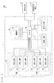
- Fig. 6 is a block diagram showing a configuration of the head lamp system 1.
- the head lamp system 1 is constituted by the head lamp unit 10, the sub-lamp unit 20 and the controller 40.
- the head lamp unit 10 includes the head lamps 11, 12.
- the sub-lamp unit 20 includes the sub-lamps 21 to 26.
- a portion of the sub-lamp unit 20 constituted by the sub-lamps 21, 23, 25 is referred to as a left sub-lamp unit 20L
- a portion of the sub-lamp unit 20 constituted by the sub-lamps 22, 24, 26 is referred to as a right sub-lamp unit 20R.
- the controller 40 includes a CPU (Central Processing Unit) 41 and a memory 42.
- a CPU Central Processing Unit
- the memory 42 threshold values of a plurality of preset bank angles are stored.
- the 10 threshold values ⁇ 1 to ⁇ 10 are stored in the memory 42.
- the CPU 41 is connected to the memory 42, the head lamps 11, 12, the sub-lamps 21 to 26, the detector 2 and the operation unit 3.
- the CPU 41 can easily switch the operation of the head lamp unit 10 between the low beam mode and the high beam mode by controlling to turn on and off the lights of the head lamps 11, 12. Further, the CPU 41 controls the operations of the sub-lamps 21 to 26 based on the plurality of threshold values stored in the memory 42, the bank angle detected by the detector 2, and the low beam mode and the high beam mode designated by the operation unit 3.
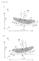
- Figs. 7 to 10(b) are diagrams showing a relationship between the bank angle and the illumination ranges during the operation of the head lamp system 1 in the low beam mode.
- Fig. 7 shows the illumination range with the motorcycle 100 not banking.
- Figs. 8(a) , 9(a) and 10(a) show the illumination ranges with the motorcycle 100 banking leftward.
- the bank angle of Fig. 10(a) is larger than the bank angle of Fig. 9(a)
- the bank angle of Fig. 9(a) is larger than the bank angle of Fig. 8(a).
- Figs. 8(b) , 9(b) and 10(b) show the illumination ranges with the motorcycle 100 banking rightward.
- the bank angle of Fig. 10(b) is larger than the bank angle of Fig. 9(b)
- the bank angle of Fig. 9(b) is larger than the bank angle of Fig. 8(b) .
- the CPU 41 lights up the head lamp 11 as shown in Fig. 7 .
- the head lamp 11 irradiates the main illumination range M1 with light.
- the range indicated by the hatching in Fig. 7 is irradiated with light.
- the main cut-off line L1 of the main illumination range M1 substantially horizontally extends.
- the CPU 41 lights up the sub-lamp 21 in addition to the head lamp 11 as shown in Fig. 8(a) .
- the head lamp 11 irradiates the main illumination range M1 with light
- the sub-lamp 21 irradiates the auxiliary illumination range A1 with light.
- the ranges indicated by the hatching in Fig. 8(a) are irradiated with light.
- the cut-off line C1 of the auxiliary illumination range A1 substantially horizontally extends.
- the CPU 41 lights up the sub-lamp 22 in addition to the head lamp 11 as shown in Fig. 8(b) .
- the head lamp 11 irradiates the main illumination range M1 with light
- the sub-lamp 22 irradiates the auxiliary illumination range A2 with light.
- the ranges indicated by the hatching in Fig. 8(b) are irradiated with light.
- the cut-off line C2 of the auxiliary illumination range A2 substantially horizontally extends.
- the CPU 41 lights up the sub-lamp 23 in addition to the head lamp 11 and the sub-lamp 21 as shown in Fig. 9(a) .
- the threshold value ⁇ 3 is larger than the threshold value ⁇ 1.
- the head lamp 11 irradiates the main illumination range M1 with light
- the sub-lamps 21, 23 respectively irradiate the auxiliary illumination ranges A1, A3 with light.
- the ranges indicated by the hatching in Fig. 9(a) are irradiated with light.
- the cut-off line C3 of the auxiliary illumination range A3 substantially horizontally extends.
- the CPU 41 lights up the sub-lamp 24 in addition to the head lamp 11 and the sub-lamp 22 as shown in Fig. 9(b) .
- the threshold value ⁇ 4 is larger than the threshold value ⁇ 2.
- the head lamp 11 irradiates the main illumination range M1 with light
- the sub-lamps 22, 24 respectively irradiate the auxiliary illumination ranges A2, A4 with light.
- the ranges indicated by the hatching in Fig. 9(b) are irradiated with light.
- the cut-off line C4 of the auxiliary illumination range A4 substantially horizontally extends.
- the CPU 41 lights up the sub-lamp 25 in addition to the head lamp 11 and the sub-lamps 21, 23 as shown in Fig. 10(a) .
- the threshold value ⁇ 7 is larger than the threshold value ⁇ 3.
- the head lamp 11 irradiates the main illumination range M1 with light
- the sub-lamps 21, 23, 25 respectively irradiate the auxiliary illumination ranges A1, A3, A5 with light.
- the ranges indicated by the hatching in Fig. 10(a) are irradiated with light.
- the cut-off line C5 of the auxiliary illumination range A5 substantially horizontally extends.
- the CPU 41 lights up the sub-lamp 26 in addition to the head lamp 11 and the sub-lamps 22, 24 as shown in Fig. 10(b) .
- the threshold value ⁇ 8 is larger than the threshold value ⁇ 4.
- the head lamp 11 irradiates the main illumination range M1 with light
- the sub-lamps 22, 24, 26 respectively irradiate the auxiliary illumination ranges A2, A4, A6 with light.
- the ranges indicated by the hatching in Fig. 10(b) are irradiated with light.
- the cut-off line C6 of the auxiliary illumination range A6 substantially horizontally extends.
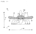
- Figs. 11 to 13(b) are diagrams showing a relationship between the bank angle and the illumination ranges during the operation of the head lamp system 1 in the high beam mode.
- Fig. 11 shows the illumination ranges with the vehicle body frame 50 not banking.
- Figs. 12(a) and 13(a) show illumination ranges with the motorcycle 100 banking leftward.
- the bank angle of Fig. 13(a) is larger than the bank angle of Fig. 12(a).
- Figs. 12(b) and 13(b) show the illumination ranges with the motorcycle 100 banking rightward.
- the bank angle of Fig. 13(b) is larger than the bank angle of Fig. 12(b) .
- the CPU 41 lights up the head lamp 12, and keeps the sub-lamps 21, 22 lit up at all times.
- the head lamp 12 irradiates the main illumination range M2 with light
- the sub-lamps 21, 22 respectively irradiate the auxiliary illumination ranges A1, A2 with light.
- a region located at a position further leftward than the left end of the main illumination range M2 and a region located at a position further rightward than the right end of the main illumination range M2 are brightly illuminated in addition to the main illumination range M2.
- the ranges indicated by the hatching in Fig. 11 are irradiated with light.
- the intensity of the light emitted from each of the sub-lamps 21, 22 during the operation in the high beam mode is equal to the intensity of the light emitted from each of the sub-lamps 21, 22 during the operation in the low beam mode.
- the intensity of the light emitted from each of the sub-lamps 21, 22 during the operation in the high beam mode may be smaller or larger than the intensity of the light emitted from each of the sub-lamps 21, 22 during the operation in the low beam mode.
- the CPU 41 lights up the sub-lamp 23 in addition to the head lamp 12 and the sub-lamps 21, 22 as shown in Fig. 12(a) .
- the head lamp 12 irradiates the main illumination range M2 with light
- the sub-lamps 21 to 23 respectively irradiate the auxiliary illumination ranges A1 to A3 with light.
- the ranges indicated by the hatching in Fig. 12(a) are irradiated with light.
- the cut-off line C3 of the auxiliary illumination range A3 substantially horizontally extends.
- the intensity of the light emitted from the sub-lamp 23 during the operation in the high beam mode is equal to the intensity of the light emitted from the sub-lamp 23 during the operation in the low beam mode.
- the CPU 41 lights up the sub-lamp 24 in addition to the head lamp 12 and the sub-lamps 21, 22 as shown in Fig. 12(b) .
- the head lamp 12 irradiates the main illumination range M2 with light
- the sub-lamps 21, 22, 24 respectively irradiate the auxiliary illumination ranges A1, A2, A4 with light.
- the ranges indicated by the hatching in Fig. 12(b) are irradiated with light.
- the cut-off line C4 of the auxiliary illumination range A4 substantially horizontally extends.
- the intensity of the light emitted from the sub-lamp 24 during the operation in the high beam mode is equal to the intensity of the light emitted from the sub-lamp 24 during the operation in the low beam mode.
- the CPU 41 lights up the sub-lamp 25 in addition to the head lamp 12 and the sub-lamps 21 to 23 as shown in Fig. 13(a) .
- the threshold value ⁇ 9 is larger than the threshold value ⁇ 5.
- the head lamp 12 irradiates the main illumination range M2 with light
- the sub-lamps 21 to 23, 25 respectively irradiate the auxiliary illumination ranges A1 to A3, A5 with light.
- the ranges indicated by the hatching in Fig. 13(a) are irradiated with light.
- the cut-off line C5 of the auxiliary illumination range A5 substantially horizontally extends.
- the intensity of the light emitted from the sub-lamp 25 during the operation in the high beam mode is equal to the intensity of the light emitted from the sub-lamp 25 during the operation in the low beam mode.
- the CPU 41 lights up the sub-lamp 26 in addition to the head lamp 12 and the sub-lamps 21, 22, 24 as shown in Fig. 13(b) .
- the threshold value ⁇ 10 is larger than the threshold value ⁇ 6.
- the head lamp 12 irradiates the main illumination range M2 with light
- the sub-lamps 21, 22, 24, 26 respectively irradiate the auxiliary illumination ranges A1, A2, A4, A6 with light.
- the ranges indicated by the hatching in Fig. 13(b) are irradiated with light.
- the cut-off line C6 of the auxiliary illumination range A6 substantially horizontally extends.
- the intensity of the light emitted from the sub-lamp 26 during the operation in the high beam mode is equal to the intensity of the light emitted from the sub-light 26 during the operation in the low beam mode.
- the threshold value ⁇ 3 and the threshold value ⁇ 5 are equal to each other, and the threshold value ⁇ 4 and the threshold value ⁇ 6 are equal to each other.
- the bank angle ⁇ L of the motorcycle 100 of when the sub-lamp 23 lights up during the operation in the low beam mode and the bank angle ⁇ L of the motorcycle 100 of when the sub-lamp 23 lights up during the operation in the high beam mode are equal to each other.
- the bank angle ⁇ R of the motorcycle 100 of when the sub-lamp 24 lights up during the operation in the low beam mode and the bank angle ⁇ R of the motorcycle 100 of when the sub-lamp 24 lights up during the operation in the high beam mode are equal to each other.
- the common control can be used to light up the sub-lamps 23, 24 during the operation in the low beam mode and the operation in the high beam mode. As a result, the control of the sub-lamp unit 20 becomes easy.
- the threshold value ⁇ 7 and the threshold value ⁇ 9 are equal to each other, and the threshold value ⁇ 8 and the threshold value ⁇ 10 are equal to each other.
- the bank angle ⁇ L of the motorcycle 100 of when the sub-lamp 25 lights up during the operation in the low beam mode is equal to the bank angle ⁇ L of the motorcycle 100 of when the sub-lamp 25 lights up during the operation in the high beam mode.
- the bank angle ⁇ R of the motorcycle 100 of when the sub-lamp 26 lights up during the operation in the low beam mode and the bank angle ⁇ R of the motorcycle 100 of when the sub-lamp 26 lights up during the operation in the high beam mode are equal to each other.
- the common control can be used to light up the sub-lamps 25, 26 during the operation in the low beam mode and during the operation in the high beam mode. As a result, the control of the sub-lamp unit 20 becomes easy.
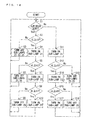
- Fig. 14 is a flow chart showing the control of the left sub-lamp unit 20L of Fig. 6 .
- the control of the left sub-lamp unit 20L by the CPU 41 will be described below according to the flow chart of Fig. 14 .
- the sub-lamps 21, 23, 25 of the left sub-lamp unit 20L are in an unlit state.
- the CPU 41 determines whether the low beam mode is designated (step S1).
- the rider can switch the operation mode between the low beam mode and the high beam mode by operating the switch (not shown) provided at the operation unit 3 of Fig. 6 .
- step S1 when the low beam mode is designated, the CPU 41 brings the head lamp 11 of Fig. 6 into a lit state, and brings the head lamp 12 into the unlit state.
- the CPU 41 determines whether the leftward bank angle ⁇ L of the motorcycle 100 is equal to the threshold value ⁇ 1 or larger than the threshold value ⁇ 1 (step S2).
- step S2 when the bank angle ⁇ L is smaller than the threshold value ⁇ 1, the CPU 41 brings the sub-lamps 21, 23, 25 into the unlit state (step S3), and returns to the process of step S1.
- step S2 when the bank angle ⁇ L is equal to the threshold value ⁇ 1 or larger than the threshold value ⁇ 1, the CPU 41 brings the sub-lamp 21 into the lit state (step S4).
- step S4 the CPU 41 determines whether the leftward bank angle ⁇ L of the motorcycle 100 is equal to the threshold value ⁇ 3 or larger than the threshold value ⁇ 3 (step S5).
- step S5 when the bank angle ⁇ L is smaller than the threshold value ⁇ 3, the CPU 41 brings the sub-lamps 23, 25 into the unlit state (step S6), and returns to the process of step S1.
- step S5 when the bank angle ⁇ L is equal to the threshold value ⁇ 3 or larger than the threshold value ⁇ 3, the CPU 41 brings the sub-lamp 23 into the lit state (step S7).
- step S7 the CPU 41 determines whether the leftward bank angle ⁇ L of the motorcycle 100 is equal to the threshold value ⁇ 7 or larger than the threshold value ⁇ 7 (step S8).
- step S8 when the bank angle ⁇ L is smaller than the threshold value ⁇ 7, the CPU 41 brings the sub-lamp 25 into the unlit state (step S9), and returns to the process of step S1.
- step S8 when the bank angle ⁇ L is equal to the threshold value ⁇ 7 or larger than the threshold value ⁇ 7, the CPU 41 brings the sub-lamp 25 into the lit state (step S10), and returns to the process of step S1.
- step S1 when the low beam mode is not designated, that is, when the high beam mode is designated, the CPU 41 brings the head lamp 12 of Fig. 6 into the lit state, and brings the head lamp 11 into the unlit state. Further, the CPU 41 brings the sub-lamp 21 into the lit state (step S11). At this time, the CPU 41 also brings the sub-lamp 22 of the right sub-lamp unit 20R into the lit state (step S31 of Fig. 15 , described below). After the process of step S11, the CPU 41 determines whether the leftward bank angle ⁇ L of the motorcycle 100 is equal to the threshold value ⁇ 5 or larger than the threshold value ⁇ 5 (step S12).
- step S12 when the bank angle ⁇ L is smaller than the threshold value ⁇ 5, the CPU 41 brings the sub-lamps 23, 25 into the unlit state (step S13), and returns to the process of step S1.
- step S12 when the bank angle ⁇ L is equal to the threshold value ⁇ 5 or larger than the threshold value ⁇ 5, the CPU 41 brings the sub-lamp 23 into the lit state (step S14).
- step S14 the CPU 41 determines whether the leftward bank angle ⁇ L of the motorcycle 100 is equal to the threshold value ⁇ 9 or larger than the threshold value ⁇ 9 (step S15).
- step S15 when the bank angle ⁇ L is smaller than the threshold value ⁇ 9, the CPU 41 brings the sub-lamp 25 into the unlit state (step S16), and returns to the process of step S1.
- step S15 when the bank angle ⁇ L is equal to the threshold value 89 or larger than the threshold value ⁇ 9, the CPU 41 brings the sub-lamp 25 into the lit state (step S17), and returns to the process of step S1.
- Fig. 15 is a flow chart showing the control of the right sub-lamp unit 20R of Fig. 6 .
- the control of the right sub-lamp unit 20R by the CPU 41 will be described below according to the flow chart of Fig. 15 .
- the sub-lamps 22, 24, 26 of the right sub-lamp unit 20R are in the unlit state.
- step S21 determines whether the low beam mode is designated.
- step S21 when the low beam mode is designated, the CPU 41 determines whether the rightward bank angle ⁇ R of the motorcycle 100 is equal to the threshold value ⁇ 2 or larger than the threshold value ⁇ 2 (step S22).
- step S22 when the bank angle ⁇ R is smaller than the threshold value ⁇ 2, the CPU 41 brings the sub-lamps 22, 24, 26 into the unlit state (step S23), and returns to the process of step S21.
- step S22 when the bank angle ⁇ R is equal to the threshold value ⁇ 2 or larger than the threshold value ⁇ 2, the CPU 41 brings the sub-lamp 22 into the lit state (step S24).
- step S24 the CPU 41 determines whether the rightward bank angle ⁇ R of the motorcycle 100 is equal to the threshold value ⁇ 4 or larger than the threshold value ⁇ 4 (step S25).
- step S25 when the bank angle ⁇ R is smaller than the threshold value ⁇ 4, the CPU 41 brings the sub-lamps 24, 26 into the unlit state (step S26), and returns to the process of step S21.
- step S25 when the bank angle ⁇ R is equal to the threshold value ⁇ 4 or larger than the threshold value ⁇ 4, the CPU 41 brings the sub-lamp 24 into the lit state (step S27).
- step S27 the CPU 41 determines whether the rightward bank angle ⁇ R of the motorcycle 100 is equal to the threshold value ⁇ 8 or larger than the threshold value ⁇ 8 (step S28).
- step S28 when the bank angle ⁇ R is smaller than the threshold value ⁇ 8, the CPU 41 brings the sub-lamp 26 into the unlit state (step S29), and returns to the process of step S21.
- step S28 when the bank angle ⁇ R is equal to the threshold value ⁇ 8 or larger than the threshold value ⁇ 8, the CPU 41 brings the sub-lamp 26 into the lit state (step S30), and returns to the process of step S21.
- step S21 when the high beam mode is designated, the CPU 41 brings the sub-lamp 22 into the lit state (step S31). At this time, the CPU 41 also brings the sub-lamp 21 of the left sub-lamp unit 20L into the lit state (step S11 of Fig. 14 ). After the process of step S31, the CPU 41 determines whether the rightward bank angle ⁇ R of the motorcycle 100 is equal to the threshold value ⁇ 6 or larger than the threshold value ⁇ 6 (step S32).
- step S32 when the bank angle ⁇ R is smaller than the threshold value ⁇ 6, the CPU 41 brings the sub-lamps 24, 26 into the unlit state (step S33), and returns to the process of step S21.
- step S32 when the bank angle ⁇ R is equal to the threshold value ⁇ 6 or larger than the threshold value ⁇ 6, the CPU 41 brings the sub-lamp 24 into the lit state (step S34).
- step S34 the CPU 41 determines whether the rightward bank angle ⁇ R of the motorcycle 100 is equal to the threshold value ⁇ 10 or larger than the threshold value ⁇ 10 (step S35).
- step S35 when the bank angle ⁇ R is smaller than the threshold value ⁇ 10, the CPU 41 brings the sub-lamp 26 into the unlit state (step S36), and returns to the process of step S21.
- step S35 when the bank angle ⁇ R is equal to the threshold value ⁇ 10 or larger than the threshold value ⁇ 10, the CPU 41 brings the sub-lamp 26 into the lit state (step S37), and returns to the process of step S21.
- the control of the above-mentioned left sub-lamp unit 20L and right sub-lamp unit 20R is performed simultaneously.
- the illumination ranges of the sub-lamps 21 to 26 can be changed as shown in Figs. 7 to 13(b) based on the bank angle detected by the detector 2 and the low beam mode and the high beam mode designated by the operation unit 3.
- the main illumination range M1 is irradiated with light by the head lamp 11, and the main illumination range M2 except for the main illumination range M1 is not irradiated with light.
- the auxiliary illumination range A1 is irradiated with light by the sub-lamp 21.
- the auxiliary illumination range A2 is irradiated with light by the sub-lamp 22.
- the area ahead of the vehicle on the right is brightly illuminated.
- the main illumination range M2 is irradiated with light by the head lamp 12.
- the light from the head lamp 12 is concentrated in a relatively narrow range. Therefore, the light can reach a far distance without an increase in the size of the head lamp 12.
- the auxiliary illumination ranges A1, A2 are irradiated with light at all times by the sub-lamps 21, 22.
- the high beam light distribution that is expanded to the left and right is acquired by the main illumination range M2 and the auxiliary illumination ranges A1, A2.
- the area farther front ahead and the area farther right and left of the vehicle can be brightly illuminated when the vehicle is travelling in a straight line and before the vehicle enters a curve.
- the rider easily confirms the conditions of the left and right of the vehicle when the vehicle is travelling in a straight line, and easily confirms the condition of the road surface before the vehicle enters a curve. It is not necessary to increase the size of the head lamp 12 or provide another sub-lamp in order to acquire the high beam light distribution that is expanded to the left and right.
- the sub-lamp 23 lights up.
- the sub-lamp 24 lights up.
- the sub-lamp 25 lights up.
- the sub-lamp 26 lights up.
- the sub-lamp 23 lights up.
- the sub-lamp 24 lights up.
- the sub-lamp 25 lights up.
- the sub-lamp 26 lights up.
- This configuration causes the area ahead of the motorcycle 100 on the left or the area ahead of the motorcycle 100 on the right to be appropriately and brightly illuminated according to the bank angle of the motorcycle 100 at the time of cornering of the vehicle.
- the preferable light distribution can be realized.
- the main cut-off line L1 of the main illumination range M1 extends in the left-and-right direction.
- the cut-off line C1 of the auxiliary illumination range A1 obliquely extends leftward and upward with respect to the main cut-off line L1.
- the cut-off line C2 of the auxiliary illumination range A2 obliquely extends rightward and upward with respect to the main cut-off line L1.
- the cut-off line C3 of the auxiliary illumination range A3 obliquely extends leftward and upward with respect to the cut-off line C1.
- the cut-off line C4 of the auxiliary illumination range A4 obliquely extends rightward and upward with respect to the cut-off line C2.
- the cut-off line C5 of the auxiliary illumination range A5 obliquely extends leftward and upward with respect to the cut-off line C3.
- the cut-off line C6 of the auxiliary illumination range A6 obliquely extends rightward and upward with respect to the cut-off line C4.
- the area ahead of the vehicle on the left is more brightly illuminated during the cornering leftward of the vehicle and the area ahead of the vehicle on the right is more brightly illuminated at the time of cornering rightward of the vehicle without an excessive increase in brightness in the area front ahead of the vehicle.
- the areas even farther left and right of the vehicle are brightly illuminated without an excessive increase in brightness in the area front ahead of the vehicle.
- the preferable light distribution can be realized during the operation in the low beam mode and during the operation in the high beam mode.
- the sub-lamp 22 does not light up.
- the invention is not limited to this.
- the sub-lamp 22 may light up.
- the intensity of the light emitted from the sub-lamp 22 is set smaller than the intensity of the light emitted from the sub-lamp 22 of when the rightward bank angle ⁇ R of the motorcycle 100 is equal to the threshold value ⁇ 2 or larger than the threshold value ⁇ 2.
- the threshold value ⁇ 7 and the threshold value ⁇ 9 are equal to each other and the threshold value ⁇ 8 and the threshold value ⁇ 10 are equal to each other in the above-mentioned embodiment, the invention is not limited to this.
- the threshold value ⁇ 7 and the threshold value ⁇ 9 do not have to be equal to each other, and the threshold value ⁇ 8 and the threshold value ⁇ 10 do not have to be equal to each other.
- differences in angle among the threshold values ⁇ 2, ⁇ 4, ⁇ 8 are not limited.
- a difference in angle between the threshold values ⁇ 2, ⁇ 4 and a difference in angle between the threshold values ⁇ 4, ⁇ 8 may be equal to each other.
- the difference in angle between the threshold value ⁇ 2, ⁇ 4 may be larger or smaller than the difference in angle between the threshold values ⁇ 4, ⁇ 8.
- the head lamp 11 that irradiates the main illumination range M1 with light, and the head lamp 12 that irradiates the main illumination range M2 with light may be arranged in the left-and-right direction.
- the head lamp 11 that irradiates the main illumination range M1 with light and the head lamp 12 that irradiates the main illumination range M2 with light may be arranged at positions vertically opposite to the example of Fig. 2 .
- the head lamp unit 10 may have the plurality of head lamps 11 that irradiate the main illumination range M1 with light and the one head lamp 12 that irradiates the main illumination range M2 with light.
- the head lamp unit 10 may have the one head lamp 11 that irradiates the main illumination range M1 with light and the plurality of head lamps 12 that irradiate the main illumination range M2 with light.
- the head lamp unit 10 may have the plurality of head lamps 11 that irradiate the main illumination range M1 with light and the plurality of head lamps 12 that irradiate the main illumination range M2 with light.
- the sub-lamp 21 that irradiates the auxiliary illumination range A1 with light and the sub-lamp 22 that irradiates the auxiliary illumination range A2 with light may be arranged at the center of the vehicle.
- the sub-lamps 21, 22 may be arranged in the top-and-bottom direction, or arranged in the left-and-right direction.
- the sub-lamp 21 that irradiates the auxiliary illumination range A1 with light and the sub-lamp 22 that irradiates the auxiliary illumination range A2 with light may be arranged at positions opposite to the example of Fig. 2 in the left-and-right direction.
- the positions at which the sub-lamps 23 to 26 are arranged are not limited to the example of Fig. 2 . As long as the sub-lamps 23 to 26 respectively irradiate the auxiliary illumination ranges A3 to A6 with light, the sub-lamps 23 to 26 may be arranged at any positions.
- the sub-lamp unit 20 may have the plurality of sub-lamps 21 that irradiate the auxiliary illumination range A1 with light and the one sub-lamp 22 that irradiates the auxiliary illumination range A2 with light.
- the sub-lamp unit 20 may have the one sub-lamp 21 that irradiates the auxiliary illumination range A1 with light and the plurality of sub-lamps 22 that irradiate the auxiliary illumination range A2 with light.
- the sub-lamp unit 20 may have the plurality of sub-lamps 21 that irradiate the auxiliary illumination range A1 with light and the plurality of sub-lamps 22 that irradiate the auxiliary illumination range A2 with light.
- the sub-lamp unit 20 has one of each sub-lamp 23 to 26 in the above-mentioned embodiment, the invention is not limited to this. As long as the sub-lamps 23 to 26 respectively irradiate the auxiliary illumination ranges A3 to A6 with light, the sub-lamp unit 20 may have any number of sub-lamps 23 to 26.
- the sub-lamp unit 20 is arranged at the cowl 70 in the above-mentioned embodiment, the invention is not limited to this. As long as the sub-lamp unit 20 is provided at the straddled vehicle and the illumination ranges change according to the bank angle of the vehicle, the sub-lamp unit 20 may be arranged at any portion of the straddled vehicle.
- the head lamp unit 10 and the sub-lamp unit 20 may be arranged at the vehicle body frame 50.
- one of the head lamp unit 10 and the sub-lamp unit 20 may be arranged at the cowl 70, and the other one may be arranged at a portion different from the cowl 70.
- the motorcycle 100 is an example of a straddled vehicle
- the head lamp system 1 is an example of a head lamp system.
- the head lamp unit 10 is an example of a head lamp unit
- the sub-lamp unit 20 is an example of a sub-lamp unit
- the controller 40 is an example of a controller
- the screen SC is an example of a virtual plane.
- the sub-lamps 21 to 26 are respectively examples of first to sixth sub-lamps
- the head lamps 11, 12 are respectively examples of first and second head lamps
- the vehicle body frame 50 is an example of a vehicle body
- the detector 2 is an example of a detector.
- the main illumination ranges M1, M2 are respectively examples of first and second main illumination ranges
- the auxiliary illumination ranges A1 to A6 are respectively examples of first to sixth auxiliary illumination ranges
- the threshold values ⁇ 1 to ⁇ 10 are respectively examples of first to tenth values.
- the main cut-off line L1 is an example of a main cut-off line
- the cut-off lines C1 to C6 are respectively examples of first to sixth cut-off lines.
- the present invention can be effectively utilized for a head lamp system and a straddled vehicle including the head lamp system.
Landscapes
- Engineering & Computer Science (AREA)
- Mechanical Engineering (AREA)
- Lighting Device Outwards From Vehicle And Optical Signal (AREA)
Applications Claiming Priority (1)
| Application Number | Priority Date | Filing Date | Title |
|---|---|---|---|
| JP2014194254A JP5946502B2 (ja) | 2014-09-24 | 2014-09-24 | ヘッドランプシステムおよび鞍乗り型車両 |
Publications (2)
| Publication Number | Publication Date |
|---|---|
| EP3000700A1 true EP3000700A1 (fr) | 2016-03-30 |
| EP3000700B1 EP3000700B1 (fr) | 2017-02-01 |
Family
ID=53900777
Family Applications (1)
| Application Number | Title | Priority Date | Filing Date |
|---|---|---|---|
| EP15181772.3A Active EP3000700B1 (fr) | 2014-09-24 | 2015-08-20 | Système de projecteurs et véhicule à selle |
Country Status (4)
| Country | Link |
|---|---|
| EP (1) | EP3000700B1 (fr) |
| JP (1) | JP5946502B2 (fr) |
| ES (1) | ES2620977T3 (fr) |
| TW (1) | TWI628103B (fr) |
Cited By (6)
| Publication number | Priority date | Publication date | Assignee | Title |
|---|---|---|---|---|
| CN108082032A (zh) * | 2018-01-30 | 2018-05-29 | 上海晨阑光电器件有限公司 | 前车灯控制装置 |
| TWI660869B (zh) * | 2017-03-14 | 2019-06-01 | 日商山葉發動機股份有限公司 | 傾斜車輛用頭燈裝置及傾斜車輛 |
| US20190366908A1 (en) * | 2018-06-05 | 2019-12-05 | Indian Motorcycle International, LLC | Adaptive Lighting System |
| US11027790B2 (en) * | 2018-06-05 | 2021-06-08 | Indian Motorcycle International, LLC | Adaptive lighting system |
| EP3703977A4 (fr) * | 2017-11-02 | 2021-07-14 | J.W. Speaker Corporation | Systèmes et procédés de matrice de phare pour un véhicule |
| US11465705B2 (en) | 2018-06-05 | 2022-10-11 | Indian Motorcycle International, LLC | Adaptive lighting system |
Families Citing this family (6)
| Publication number | Priority date | Publication date | Assignee | Title |
|---|---|---|---|---|
| WO2021005666A1 (fr) * | 2019-07-05 | 2021-01-14 | ヤマハ発動機株式会社 | Dispositif de phare et véhicule inclinable comprenant ledit dispositif de phare |
| JP6987171B2 (ja) * | 2020-03-31 | 2021-12-22 | ヤマハ発動機株式会社 | ヘッドライト装置 |
| JP7504733B2 (ja) | 2020-09-14 | 2024-06-24 | 株式会社小糸製作所 | 車両用灯具および車両システム |
| JP7532544B2 (ja) * | 2020-10-21 | 2024-08-13 | ヤマハ発動機株式会社 | ヘッドライト装置、及び傾斜車両 |
| DE112021005521T5 (de) * | 2020-10-21 | 2023-08-24 | Yamaha Hatsudoki Kabushiki Kaisha | Scheinwerfervorrichtung und Neigungsfahrzeug |
| JP7357828B2 (ja) * | 2021-08-30 | 2023-10-06 | 三菱電機株式会社 | 二輪車用灯具 |
Citations (6)
| Publication number | Priority date | Publication date | Assignee | Title |
|---|---|---|---|---|
| EP1748251A1 (fr) * | 2005-07-26 | 2007-01-31 | Valeo Vision | Dispositif d'éclairage pour véhicule automobile |
| JP2008222178A (ja) | 2007-03-15 | 2008-09-25 | Koito Mfg Co Ltd | 二輪車用前照灯 |
| EP2641780A2 (fr) * | 2012-03-19 | 2013-09-25 | Yamaha Hatsudoki Kabushiki Kaisha | Sous-bloc optique et système de bloc optique à utiliser dans un véhicule qui penche dans les virages et véhicule qui penche dans les virages et procédé de contrôle de l'émission lumineuse d'un sous-bloc optique |
| JP2013193561A (ja) | 2012-03-19 | 2013-09-30 | Yamaha Motor Co Ltd | リーン姿勢で旋回する車両用のサブヘッドライトユニット及びサブヘッドライトシステム、並びにリーン姿勢で旋回する車両 |
| EP2676872A1 (fr) * | 2012-06-18 | 2013-12-25 | Yamaha Hatsudoki Kabushiki Kaisha | Sous-bloc optique, bloc optique, système de bloc optique pour véhicule qui penche dans les virages, véhicule qui penche dans les virages et procédé pour commander le sous-bloc optique pour véhicule qui penche dans les virages |
| JP5525638B1 (ja) * | 2013-04-17 | 2014-06-18 | ヤマハ発動機株式会社 | リーン姿勢で旋回する車両用のライトユニット及びその調整方法、並びにリーン姿勢で旋回する車両及びその調整方法 |
Family Cites Families (1)
| Publication number | Priority date | Publication date | Assignee | Title |
|---|---|---|---|---|
| JP3343985B2 (ja) * | 1993-03-29 | 2002-11-11 | スズキ株式会社 | 車輌用コーナリングランプの点灯回路 |
-
2014
- 2014-09-24 JP JP2014194254A patent/JP5946502B2/ja active Active
-
2015
- 2015-08-19 TW TW104127054A patent/TWI628103B/zh active
- 2015-08-20 ES ES15181772.3T patent/ES2620977T3/es active Active
- 2015-08-20 EP EP15181772.3A patent/EP3000700B1/fr active Active
Patent Citations (6)
| Publication number | Priority date | Publication date | Assignee | Title |
|---|---|---|---|---|
| EP1748251A1 (fr) * | 2005-07-26 | 2007-01-31 | Valeo Vision | Dispositif d'éclairage pour véhicule automobile |
| JP2008222178A (ja) | 2007-03-15 | 2008-09-25 | Koito Mfg Co Ltd | 二輪車用前照灯 |
| EP2641780A2 (fr) * | 2012-03-19 | 2013-09-25 | Yamaha Hatsudoki Kabushiki Kaisha | Sous-bloc optique et système de bloc optique à utiliser dans un véhicule qui penche dans les virages et véhicule qui penche dans les virages et procédé de contrôle de l'émission lumineuse d'un sous-bloc optique |
| JP2013193561A (ja) | 2012-03-19 | 2013-09-30 | Yamaha Motor Co Ltd | リーン姿勢で旋回する車両用のサブヘッドライトユニット及びサブヘッドライトシステム、並びにリーン姿勢で旋回する車両 |
| EP2676872A1 (fr) * | 2012-06-18 | 2013-12-25 | Yamaha Hatsudoki Kabushiki Kaisha | Sous-bloc optique, bloc optique, système de bloc optique pour véhicule qui penche dans les virages, véhicule qui penche dans les virages et procédé pour commander le sous-bloc optique pour véhicule qui penche dans les virages |
| JP5525638B1 (ja) * | 2013-04-17 | 2014-06-18 | ヤマハ発動機株式会社 | リーン姿勢で旋回する車両用のライトユニット及びその調整方法、並びにリーン姿勢で旋回する車両及びその調整方法 |
Cited By (16)
| Publication number | Priority date | Publication date | Assignee | Title |
|---|---|---|---|---|
| TWI660869B (zh) * | 2017-03-14 | 2019-06-01 | 日商山葉發動機股份有限公司 | 傾斜車輛用頭燈裝置及傾斜車輛 |
| EP4357227A3 (fr) * | 2017-03-14 | 2024-07-31 | Yamaha Hatsudoki Kabushiki Kaisha | Appareil de phare de véhicule incliné et véhicule incliné |
| EP3530556A4 (fr) * | 2017-03-14 | 2019-12-25 | Yamaha Hatsudoki Kabushiki Kaisha | Appareil de phare de véhicule incliné et véhicule incliné |
| EP3703977A4 (fr) * | 2017-11-02 | 2021-07-14 | J.W. Speaker Corporation | Systèmes et procédés de matrice de phare pour un véhicule |
| US11407354B2 (en) | 2017-11-02 | 2022-08-09 | J.W. Speaker Corporation | Headlight matrix systems and methods for a vehicle |
| CN108082032A (zh) * | 2018-01-30 | 2018-05-29 | 上海晨阑光电器件有限公司 | 前车灯控制装置 |
| CN108082032B (zh) * | 2018-01-30 | 2023-07-21 | 上海晨阑光电器件有限公司 | 前车灯控制装置 |
| WO2019236601A3 (fr) * | 2018-06-05 | 2020-03-12 | Indian Motorcycle International, LLC | Système d'éclairage adaptatif |
| US11027790B2 (en) * | 2018-06-05 | 2021-06-08 | Indian Motorcycle International, LLC | Adaptive lighting system |
| US11465705B2 (en) | 2018-06-05 | 2022-10-11 | Indian Motorcycle International, LLC | Adaptive lighting system |
| EP4129807A3 (fr) * | 2018-06-05 | 2023-04-19 | Indian Motorcycle International, LLC | Système d'éclairage adaptatif |
| US10850661B2 (en) | 2018-06-05 | 2020-12-01 | Indian Motorcycle International, LLC | Adaptive lighting system |
| US11878757B2 (en) | 2018-06-05 | 2024-01-23 | Indian Motorcycle International, LLC | Adaptive lighting system |
| US11981387B2 (en) | 2018-06-05 | 2024-05-14 | Indian Motorcycle International, LLC | Adaptive lighting system |
| EP4339026A3 (fr) * | 2018-06-05 | 2024-05-15 | Indian Motorcycle International, LLC | Système d'éclairage adaptatif |
| US20190366908A1 (en) * | 2018-06-05 | 2019-12-05 | Indian Motorcycle International, LLC | Adaptive Lighting System |
Also Published As
| Publication number | Publication date |
|---|---|
| JP2016064723A (ja) | 2016-04-28 |
| JP5946502B2 (ja) | 2016-07-06 |
| TW201612054A (en) | 2016-04-01 |
| ES2620977T3 (es) | 2017-06-30 |
| EP3000700B1 (fr) | 2017-02-01 |
| TWI628103B (zh) | 2018-07-01 |
Similar Documents
| Publication | Publication Date | Title |
|---|---|---|
| EP3000700B1 (fr) | Système de projecteurs et véhicule à selle | |
| JP5615870B2 (ja) | リーン姿勢で旋回する車両用のサブヘッドライトユニット及びサブヘッドライトシステム、並びにリーン姿勢で旋回する車両 | |
| US8937431B2 (en) | Sub headlight unit and sub headlight system for use in vehicle that leans into turns, and vehicle that leans into turns | |
| JP5719620B2 (ja) | 車両用前照灯の配光制御装置 | |
| EP3187399B1 (fr) | Phares de motocycle adaptés pour l'éclairage en virage | |
| EP2266838B1 (fr) | Dispositif de phare de véhicule | |
| US20080225271A1 (en) | Vehicle Operation Support Method and System | |
| JP6710048B2 (ja) | 乗物 | |
| EP2495129B1 (fr) | Dispositif de contrôle de distribution d'éclairage | |
| JP6506962B2 (ja) | 鞍乗型車両 | |
| JP2013230774A (ja) | リーン姿勢で旋回する車両用のヘッドライトユニット及びヘッドライトシステム、並びにリーン姿勢で旋回する車両 | |
| JP2014000875A (ja) | リーン姿勢で旋回する車両用のサブヘッドライトユニット、ヘッドライトユニット及びヘッドライトシステム、並びにリーン姿勢で旋回する車両 | |
| EP2669163B1 (fr) | Sous-bloc optique, procédé de commande d'un sous-bloc optique et système de bloc optique pour véhicule qui penche dans les virages et véhicule qui penche dans les virages | |
| JP6266860B2 (ja) | 二輪車用ヘッドランプ | |
| EP2196357A1 (fr) | Dispositif d'éclairage automobile | |
| JP2010143483A (ja) | 車両用前照灯装置およびその制御方法 | |
| JP2004136864A (ja) | 自動車用ランプのための防眩安全装置 | |
| KR20090114582A (ko) | 듀얼 헤드램프 시스템 | |
| JP6905309B2 (ja) | 乗物 | |
| JP2007145233A (ja) | 光照射システム | |
| TW202222612A (zh) | 頭燈裝置及傾斜車輛 | |
| CN115009151A (zh) | 前照灯控制系统 | |
| JP2008230546A (ja) | 車両の運転支援装置 | |
| JP2007045256A (ja) | 車両用前照灯装置 |
Legal Events
| Date | Code | Title | Description |
|---|---|---|---|
| PUAI | Public reference made under article 153(3) epc to a published international application that has entered the european phase |
Free format text: ORIGINAL CODE: 0009012 |
|
| 17P | Request for examination filed |
Effective date: 20150820 |
|
| AK | Designated contracting states |
Kind code of ref document: A1 Designated state(s): AL AT BE BG CH CY CZ DE DK EE ES FI FR GB GR HR HU IE IS IT LI LT LU LV MC MK MT NL NO PL PT RO RS SE SI SK SM TR |
|
| AX | Request for extension of the european patent |
Extension state: BA ME |
|
| RBV | Designated contracting states (corrected) |
Designated state(s): AL AT BE BG CH CY CZ DE DK EE ES FI FR GB GR HR HU IE IS IT LI LT LU LV MC MK MT NL NO PL PT RO RS SE SI SK SM TR |
|
| GRAP | Despatch of communication of intention to grant a patent |
Free format text: ORIGINAL CODE: EPIDOSNIGR1 |
|
| RIC1 | Information provided on ipc code assigned before grant |
Ipc: B60Q 1/14 20060101ALI20160705BHEP Ipc: B62J 6/02 20060101AFI20160705BHEP Ipc: B60Q 1/12 20060101ALI20160705BHEP |
|
| INTG | Intention to grant announced |
Effective date: 20160805 |
|
| GRAS | Grant fee paid |
Free format text: ORIGINAL CODE: EPIDOSNIGR3 |
|
| GRAA | (expected) grant |
Free format text: ORIGINAL CODE: 0009210 |
|
| AK | Designated contracting states |
Kind code of ref document: B1 Designated state(s): AL AT BE BG CH CY CZ DE DK EE ES FI FR GB GR HR HU IE IS IT LI LT LU LV MC MK MT NL NO PL PT RO RS SE SI SK SM TR |
|
| REG | Reference to a national code |
Ref country code: GB Ref legal event code: FG4D |
|
| REG | Reference to a national code |
Ref country code: CH Ref legal event code: EP Ref country code: AT Ref legal event code: REF Ref document number: 865300 Country of ref document: AT Kind code of ref document: T Effective date: 20170215 |
|
| REG | Reference to a national code |
Ref country code: IE Ref legal event code: FG4D |
|
| REG | Reference to a national code |
Ref country code: DE Ref legal event code: R096 Ref document number: 602015001419 Country of ref document: DE |
|
| REG | Reference to a national code |
Ref country code: NL Ref legal event code: MP Effective date: 20170201 |
|
| REG | Reference to a national code |
Ref country code: LT Ref legal event code: MG4D |
|
| REG | Reference to a national code |
Ref country code: AT Ref legal event code: MK05 Ref document number: 865300 Country of ref document: AT Kind code of ref document: T Effective date: 20170201 |
|
| REG | Reference to a national code |
Ref country code: ES Ref legal event code: FG2A Ref document number: 2620977 Country of ref document: ES Kind code of ref document: T3 Effective date: 20170630 |
|
| PG25 | Lapsed in a contracting state [announced via postgrant information from national office to epo] |
Ref country code: GR Free format text: LAPSE BECAUSE OF FAILURE TO SUBMIT A TRANSLATION OF THE DESCRIPTION OR TO PAY THE FEE WITHIN THE PRESCRIBED TIME-LIMIT Effective date: 20170502 Ref country code: FI Free format text: LAPSE BECAUSE OF FAILURE TO SUBMIT A TRANSLATION OF THE DESCRIPTION OR TO PAY THE FEE WITHIN THE PRESCRIBED TIME-LIMIT Effective date: 20170201 Ref country code: IS Free format text: LAPSE BECAUSE OF FAILURE TO SUBMIT A TRANSLATION OF THE DESCRIPTION OR TO PAY THE FEE WITHIN THE PRESCRIBED TIME-LIMIT Effective date: 20170601 Ref country code: HR Free format text: LAPSE BECAUSE OF FAILURE TO SUBMIT A TRANSLATION OF THE DESCRIPTION OR TO PAY THE FEE WITHIN THE PRESCRIBED TIME-LIMIT Effective date: 20170201 Ref country code: NO Free format text: LAPSE BECAUSE OF FAILURE TO SUBMIT A TRANSLATION OF THE DESCRIPTION OR TO PAY THE FEE WITHIN THE PRESCRIBED TIME-LIMIT Effective date: 20170501 Ref country code: LT Free format text: LAPSE BECAUSE OF FAILURE TO SUBMIT A TRANSLATION OF THE DESCRIPTION OR TO PAY THE FEE WITHIN THE PRESCRIBED TIME-LIMIT Effective date: 20170201 |
|
| REG | Reference to a national code |
Ref country code: FR Ref legal event code: PLFP Year of fee payment: 3 |
|
| PG25 | Lapsed in a contracting state [announced via postgrant information from national office to epo] |
Ref country code: RS Free format text: LAPSE BECAUSE OF FAILURE TO SUBMIT A TRANSLATION OF THE DESCRIPTION OR TO PAY THE FEE WITHIN THE PRESCRIBED TIME-LIMIT Effective date: 20170201 Ref country code: NL Free format text: LAPSE BECAUSE OF NON-PAYMENT OF DUE FEES Effective date: 20170201 Ref country code: AT Free format text: LAPSE BECAUSE OF FAILURE TO SUBMIT A TRANSLATION OF THE DESCRIPTION OR TO PAY THE FEE WITHIN THE PRESCRIBED TIME-LIMIT Effective date: 20170201 Ref country code: LV Free format text: LAPSE BECAUSE OF FAILURE TO SUBMIT A TRANSLATION OF THE DESCRIPTION OR TO PAY THE FEE WITHIN THE PRESCRIBED TIME-LIMIT Effective date: 20170201 Ref country code: SE Free format text: LAPSE BECAUSE OF FAILURE TO SUBMIT A TRANSLATION OF THE DESCRIPTION OR TO PAY THE FEE WITHIN THE PRESCRIBED TIME-LIMIT Effective date: 20170201 Ref country code: PL Free format text: LAPSE BECAUSE OF FAILURE TO SUBMIT A TRANSLATION OF THE DESCRIPTION OR TO PAY THE FEE WITHIN THE PRESCRIBED TIME-LIMIT Effective date: 20170201 Ref country code: BG Free format text: LAPSE BECAUSE OF FAILURE TO SUBMIT A TRANSLATION OF THE DESCRIPTION OR TO PAY THE FEE WITHIN THE PRESCRIBED TIME-LIMIT Effective date: 20170501 Ref country code: PT Free format text: LAPSE BECAUSE OF FAILURE TO SUBMIT A TRANSLATION OF THE DESCRIPTION OR TO PAY THE FEE WITHIN THE PRESCRIBED TIME-LIMIT Effective date: 20170601 |
|
| PG25 | Lapsed in a contracting state [announced via postgrant information from national office to epo] |
Ref country code: SK Free format text: LAPSE BECAUSE OF FAILURE TO SUBMIT A TRANSLATION OF THE DESCRIPTION OR TO PAY THE FEE WITHIN THE PRESCRIBED TIME-LIMIT Effective date: 20170201 Ref country code: CZ Free format text: LAPSE BECAUSE OF FAILURE TO SUBMIT A TRANSLATION OF THE DESCRIPTION OR TO PAY THE FEE WITHIN THE PRESCRIBED TIME-LIMIT Effective date: 20170201 Ref country code: RO Free format text: LAPSE BECAUSE OF FAILURE TO SUBMIT A TRANSLATION OF THE DESCRIPTION OR TO PAY THE FEE WITHIN THE PRESCRIBED TIME-LIMIT Effective date: 20170201 Ref country code: EE Free format text: LAPSE BECAUSE OF FAILURE TO SUBMIT A TRANSLATION OF THE DESCRIPTION OR TO PAY THE FEE WITHIN THE PRESCRIBED TIME-LIMIT Effective date: 20170201 |
|
| REG | Reference to a national code |
Ref country code: DE Ref legal event code: R097 Ref document number: 602015001419 Country of ref document: DE |
|
| PG25 | Lapsed in a contracting state [announced via postgrant information from national office to epo] |
Ref country code: DK Free format text: LAPSE BECAUSE OF FAILURE TO SUBMIT A TRANSLATION OF THE DESCRIPTION OR TO PAY THE FEE WITHIN THE PRESCRIBED TIME-LIMIT Effective date: 20170201 Ref country code: SM Free format text: LAPSE BECAUSE OF FAILURE TO SUBMIT A TRANSLATION OF THE DESCRIPTION OR TO PAY THE FEE WITHIN THE PRESCRIBED TIME-LIMIT Effective date: 20170201 |
|
| PLBE | No opposition filed within time limit |
Free format text: ORIGINAL CODE: 0009261 |
|
| STAA | Information on the status of an ep patent application or granted ep patent |
Free format text: STATUS: NO OPPOSITION FILED WITHIN TIME LIMIT |
|
| 26N | No opposition filed |
Effective date: 20171103 |
|
| PG25 | Lapsed in a contracting state [announced via postgrant information from national office to epo] |
Ref country code: SI Free format text: LAPSE BECAUSE OF FAILURE TO SUBMIT A TRANSLATION OF THE DESCRIPTION OR TO PAY THE FEE WITHIN THE PRESCRIBED TIME-LIMIT Effective date: 20170201 |
|
| PG25 | Lapsed in a contracting state [announced via postgrant information from national office to epo] |
Ref country code: MC Free format text: LAPSE BECAUSE OF FAILURE TO SUBMIT A TRANSLATION OF THE DESCRIPTION OR TO PAY THE FEE WITHIN THE PRESCRIBED TIME-LIMIT Effective date: 20170201 |
|
| REG | Reference to a national code |
Ref country code: BE Ref legal event code: MM Effective date: 20170831 |
|
| REG | Reference to a national code |
Ref country code: IE Ref legal event code: MM4A |
|
| PG25 | Lapsed in a contracting state [announced via postgrant information from national office to epo] |
Ref country code: LU Free format text: LAPSE BECAUSE OF NON-PAYMENT OF DUE FEES Effective date: 20170820 |
|
| PG25 | Lapsed in a contracting state [announced via postgrant information from national office to epo] |
Ref country code: IE Free format text: LAPSE BECAUSE OF NON-PAYMENT OF DUE FEES Effective date: 20170820 |
|
| REG | Reference to a national code |
Ref country code: FR Ref legal event code: PLFP Year of fee payment: 4 |
|
| PG25 | Lapsed in a contracting state [announced via postgrant information from national office to epo] |
Ref country code: BE Free format text: LAPSE BECAUSE OF NON-PAYMENT OF DUE FEES Effective date: 20170831 |
|
| PG25 | Lapsed in a contracting state [announced via postgrant information from national office to epo] |
Ref country code: MT Free format text: LAPSE BECAUSE OF NON-PAYMENT OF DUE FEES Effective date: 20170820 |
|
| REG | Reference to a national code |
Ref country code: CH Ref legal event code: PL |
|
| PG25 | Lapsed in a contracting state [announced via postgrant information from national office to epo] |
Ref country code: LI Free format text: LAPSE BECAUSE OF NON-PAYMENT OF DUE FEES Effective date: 20180831 Ref country code: CH Free format text: LAPSE BECAUSE OF NON-PAYMENT OF DUE FEES Effective date: 20180831 |
|
| PG25 | Lapsed in a contracting state [announced via postgrant information from national office to epo] |
Ref country code: HU Free format text: LAPSE BECAUSE OF FAILURE TO SUBMIT A TRANSLATION OF THE DESCRIPTION OR TO PAY THE FEE WITHIN THE PRESCRIBED TIME-LIMIT; INVALID AB INITIO Effective date: 20150820 |
|
| PG25 | Lapsed in a contracting state [announced via postgrant information from national office to epo] |
Ref country code: CY Free format text: LAPSE BECAUSE OF FAILURE TO SUBMIT A TRANSLATION OF THE DESCRIPTION OR TO PAY THE FEE WITHIN THE PRESCRIBED TIME-LIMIT Effective date: 20170201 |
|
| PG25 | Lapsed in a contracting state [announced via postgrant information from national office to epo] |
Ref country code: MK Free format text: LAPSE BECAUSE OF FAILURE TO SUBMIT A TRANSLATION OF THE DESCRIPTION OR TO PAY THE FEE WITHIN THE PRESCRIBED TIME-LIMIT Effective date: 20170201 |
|
| PG25 | Lapsed in a contracting state [announced via postgrant information from national office to epo] |
Ref country code: TR Free format text: LAPSE BECAUSE OF FAILURE TO SUBMIT A TRANSLATION OF THE DESCRIPTION OR TO PAY THE FEE WITHIN THE PRESCRIBED TIME-LIMIT Effective date: 20170201 |
|
| PG25 | Lapsed in a contracting state [announced via postgrant information from national office to epo] |
Ref country code: AL Free format text: LAPSE BECAUSE OF FAILURE TO SUBMIT A TRANSLATION OF THE DESCRIPTION OR TO PAY THE FEE WITHIN THE PRESCRIBED TIME-LIMIT Effective date: 20170201 |
|
| P01 | Opt-out of the competence of the unified patent court (upc) registered |
Effective date: 20230527 |
|
| PGFP | Annual fee paid to national office [announced via postgrant information from national office to epo] |
Ref country code: IT Payment date: 20230825 Year of fee payment: 9 Ref country code: GB Payment date: 20230822 Year of fee payment: 9 |
|
| PGFP | Annual fee paid to national office [announced via postgrant information from national office to epo] |
Ref country code: FR Payment date: 20230824 Year of fee payment: 9 Ref country code: DE Payment date: 20230821 Year of fee payment: 9 |
|
| PGFP | Annual fee paid to national office [announced via postgrant information from national office to epo] |
Ref country code: ES Payment date: 20231027 Year of fee payment: 9 |