EP3000230B1 - Stereoscopic picture generation apparatus and stereoscopic picture generation method - Google Patents
Stereoscopic picture generation apparatus and stereoscopic picture generation method Download PDFInfo
- Publication number
- EP3000230B1 EP3000230B1 EP14762101.5A EP14762101A EP3000230B1 EP 3000230 B1 EP3000230 B1 EP 3000230B1 EP 14762101 A EP14762101 A EP 14762101A EP 3000230 B1 EP3000230 B1 EP 3000230B1
- Authority
- EP
- European Patent Office
- Prior art keywords
- picture
- unit
- areas
- pickup
- area
- Prior art date
- Legal status (The legal status is an assumption and is not a legal conclusion. Google has not performed a legal analysis and makes no representation as to the accuracy of the status listed.)
- Not-in-force
Links
Images


Classifications
-
- H—ELECTRICITY
- H04—ELECTRIC COMMUNICATION TECHNIQUE
- H04N—PICTORIAL COMMUNICATION, e.g. TELEVISION
- H04N13/00—Stereoscopic video systems; Multi-view video systems; Details thereof
- H04N13/20—Image signal generators
- H04N13/204—Image signal generators using stereoscopic image cameras
- H04N13/207—Image signal generators using stereoscopic image cameras using a single 2D image sensor
- H04N13/211—Image signal generators using stereoscopic image cameras using a single 2D image sensor using temporal multiplexing
-
- A—HUMAN NECESSITIES
- A61—MEDICAL OR VETERINARY SCIENCE; HYGIENE
- A61B—DIAGNOSIS; SURGERY; IDENTIFICATION
- A61B1/00—Instruments for performing medical examinations of the interior of cavities or tubes of the body by visual or photographical inspection, e.g. endoscopes; Illuminating arrangements therefor
- A61B1/00163—Optical arrangements
- A61B1/00193—Optical arrangements adapted for stereoscopic vision
-
- G—PHYSICS
- G02—OPTICS
- G02B—OPTICAL ELEMENTS, SYSTEMS OR APPARATUS
- G02B21/00—Microscopes
- G02B21/0004—Microscopes specially adapted for specific applications
- G02B21/0012—Surgical microscopes
-
- G—PHYSICS
- G02—OPTICS
- G02B—OPTICAL ELEMENTS, SYSTEMS OR APPARATUS
- G02B21/00—Microscopes
- G02B21/18—Arrangements with more than one light path, e.g. for comparing two specimens
- G02B21/20—Binocular arrangements
- G02B21/22—Stereoscopic arrangements
-
- H—ELECTRICITY
- H04—ELECTRIC COMMUNICATION TECHNIQUE
- H04N—PICTORIAL COMMUNICATION, e.g. TELEVISION
- H04N13/00—Stereoscopic video systems; Multi-view video systems; Details thereof
- H04N13/20—Image signal generators
- H04N13/282—Image signal generators for generating image signals corresponding to three or more geometrical viewpoints, e.g. multi-view systems
-
- H—ELECTRICITY
- H04—ELECTRIC COMMUNICATION TECHNIQUE
- H04N—PICTORIAL COMMUNICATION, e.g. TELEVISION
- H04N23/00—Cameras or camera modules comprising electronic image sensors; Control thereof
- H04N23/60—Control of cameras or camera modules
-
- H—ELECTRICITY
- H04—ELECTRIC COMMUNICATION TECHNIQUE
- H04N—PICTORIAL COMMUNICATION, e.g. TELEVISION
- H04N23/00—Cameras or camera modules comprising electronic image sensors; Control thereof
- H04N23/80—Camera processing pipelines; Components thereof
- H04N23/84—Camera processing pipelines; Components thereof for processing colour signals
- H04N23/843—Demosaicing, e.g. interpolating colour pixel values
-
- H—ELECTRICITY
- H04—ELECTRIC COMMUNICATION TECHNIQUE
- H04N—PICTORIAL COMMUNICATION, e.g. TELEVISION
- H04N25/00—Circuitry of solid-state image sensors [SSIS]; Control thereof
- H04N25/10—Circuitry of solid-state image sensors [SSIS]; Control thereof for transforming different wavelengths into image signals
- H04N25/11—Arrangement of colour filter arrays [CFA]; Filter mosaics
- H04N25/13—Arrangement of colour filter arrays [CFA]; Filter mosaics characterised by the spectral characteristics of the filter elements
- H04N25/134—Arrangement of colour filter arrays [CFA]; Filter mosaics characterised by the spectral characteristics of the filter elements based on three different wavelength filter elements
-
- A—HUMAN NECESSITIES
- A61—MEDICAL OR VETERINARY SCIENCE; HYGIENE
- A61B—DIAGNOSIS; SURGERY; IDENTIFICATION
- A61B1/00—Instruments for performing medical examinations of the interior of cavities or tubes of the body by visual or photographical inspection, e.g. endoscopes; Illuminating arrangements therefor
- A61B1/06—Instruments for performing medical examinations of the interior of cavities or tubes of the body by visual or photographical inspection, e.g. endoscopes; Illuminating arrangements therefor with illuminating arrangements
- A61B1/063—Instruments for performing medical examinations of the interior of cavities or tubes of the body by visual or photographical inspection, e.g. endoscopes; Illuminating arrangements therefor with illuminating arrangements for monochromatic or narrow-band illumination
-
- A—HUMAN NECESSITIES
- A61—MEDICAL OR VETERINARY SCIENCE; HYGIENE
- A61B—DIAGNOSIS; SURGERY; IDENTIFICATION
- A61B1/00—Instruments for performing medical examinations of the interior of cavities or tubes of the body by visual or photographical inspection, e.g. endoscopes; Illuminating arrangements therefor
- A61B1/06—Instruments for performing medical examinations of the interior of cavities or tubes of the body by visual or photographical inspection, e.g. endoscopes; Illuminating arrangements therefor with illuminating arrangements
- A61B1/0638—Instruments for performing medical examinations of the interior of cavities or tubes of the body by visual or photographical inspection, e.g. endoscopes; Illuminating arrangements therefor with illuminating arrangements providing two or more wavelengths
-
- G—PHYSICS
- G02—OPTICS
- G02B—OPTICAL ELEMENTS, SYSTEMS OR APPARATUS
- G02B23/00—Telescopes, e.g. binoculars; Periscopes; Instruments for viewing the inside of hollow bodies; Viewfinders; Optical aiming or sighting devices
- G02B23/24—Instruments or systems for viewing the inside of hollow bodies, e.g. fibrescopes
- G02B23/2407—Optical details
- G02B23/2415—Stereoscopic endoscopes
-
- H—ELECTRICITY
- H04—ELECTRIC COMMUNICATION TECHNIQUE
- H04N—PICTORIAL COMMUNICATION, e.g. TELEVISION
- H04N23/00—Cameras or camera modules comprising electronic image sensors; Control thereof
- H04N23/50—Constructional details
- H04N23/555—Constructional details for picking-up images in sites, inaccessible due to their dimensions or hazardous conditions, e.g. endoscopes or borescopes
Definitions
- the present technology relates to a technical field of a stereoscopic picture generation apparatus for generating a stereoscopic picture and a method therefor.
- an operation microscope that is used in, for example, surgical operations, and can present a stereoscopic picture for an observed subject (see PTL 1, for example).
- a stereoscopic picture for an observed subject.
- the left-eye picture is presented to the left eye of an observer, and the right-eye picture is presented to the right eye.
- the stereoscopic vision is actualized.
- PTL 1 discloses a technology that, when a plurality of observers, for example, an operator such as an operating surgeon and his assistants, observe a subject through monitors from different angle directions respectively, generates pictures corresponding to the angle directions of the positions of the respective observers.
- the "angle direction” mentioned here means a radial angle direction centering on the subject, which is defined as 0 deg (degree) to 360 deg.
- the technology described in PTL 1 allows the respective observers to perform the observation from arbitrary angle directions, by a plurality of stereoscopic monitors 48 attached so as to be rotatable around a mirror body 12 in which an optical system such as an objective lens 32 is incorporated.
- the information about the rotation position (angle) of the stereoscopic monitor 48 is input as the information about the angle direction of the position of the observer, and the stereoscopic monitor 48 presents a picture corresponding to the angle direction, that is, a stereoscopic picture by a picture observed from the viewpoint of the left eye of the observer and a picture observed from the viewpoint of the right eye when the observer views the subject from the angle direction.
- the pictures picked up on a viewpoint basis two pictures corresponding to the angle direction of the position of the observer, that is, a picture observed from the viewpoint of the left eye of the observer who is at the position in the angle direction and a picture observed from the viewpoint of the right eye are selected. Then, they are displayed on the stereoscopic monitor 48 as a left-eye picture and a right-eye picture, and thereby the stereoscopic picture is presented.
- US2012/0019736 relates to an imaging device.
- the technology described in PTL 1 makes it possible to individually pick up the images that have passed through the respective areas that are formed by the division in the direction around the optical axis, in order to allow for the observation from the plurality of angle directions.
- various components may be an independent device or may be a module to be incorporated into other devices.
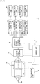
- FIG. 1 is a block diagram showing an internal configuration of a stereoscopic picture generation apparatus 1 according to a first embodiment of the present technology.
- the stereoscopic picture generation apparatus 1 which is, for example, an operation microscope, includes four display units (a first display unit 6-1 to a fourth display unit 6-4) for presenting stereoscopic pictures for an observation subject X to observers. These four display units allow the stereoscopic pictures for the subject X to be simultaneously presented to four observers.
- the attachment positions of the first display unit 6-1 to the fourth display unit 6-4 are each fixed. That is, it is assumed that the angle direction of the position of each observer is fixed.
- the "angle direction” mentioned herein means a radial angle direction centering on the subject X, which is defined as 0 deg (degree) to 360 deg.
- the increasing direction of the angle value (deg) indicating the angle direction matches the clockwise direction when the subject X is viewed from straight above.
- FIG. 2B shows a positional relation of the left eye (L) and right eye (R) of an observer relative to the subject X when the observer observes the subject X from the angle direction of 0 deg.
- FIG. 2C to FIG. 2E show positional relations of the left eye and right eye of the observer relative to the subject X when the observer observes the subject X from the angle directions of 90 deg, 180 deg and 270 deg, respectively.
- the difference in the angle direction of the position of the observer leads to the difference in the positional relation of the left eye and right eye of the observer relative to the subject X.
- the first display unit 6-1 is fixed such that the display surface is oriented in the angle direction of 0 deg
- the second display unit 6-2 is fixed such that the display surface is oriented in the angle direction of 90 deg
- the third display unit 6-3 is fixed such that the display surface is oriented in the angle direction of 180 deg
- the fourth display unit 6-4 is fixed such that the display surface is oriented in the angle direction of 270 deg.
- the standing position of the observer is in either angle direction of 0 deg, 90 deg, 180 deg and 270 deg.
- the stereoscopic picture generation apparatus 1 includes an optical unit 2, a picture pickup element 3, a left-right picture individual-generation unit 4, a first display control unit 5-1 to a fourth display control unit 5-4, a control unit 7 and an illumination unit 8.
- a condensing lens 21, a pupil division unit 22, and an imaging lens 23 are arranged in that order from the body side (photographic subject side).
- the condensing lens 21 condenses light from the subject X that is a photographic subject.
- the pupil division unit 22 is provided at such a position that the light condensed by the condensing lens 21 becomes roughly parallel light, and the light through the condensing lens 21 enters the pupil division unit 22.
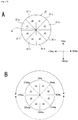
- FIG. 3 is an explanatory diagram for a configuration of the pupil division unit 22.
- the pupil division unit 22 is viewed from the image surface side.
- the pupil division unit 22 according to the embodiment is divided into four areas A, by two dividing lines (pupil dividing lines) that intersect with the optical axis Ox.
- FIG. 3 shows the relation between the pupil division unit 22 and the angle direction, by additionally writing the angle directions on the basis of the subject X.
- one dividing line is parallel to the 0 deg-180 deg axis and the other dividing line is parallel to the 90 deg-270 deg axis, so that the four areas A are even areas.
- an area A of 0 deg to 90 deg is referred to as an "area A1”
- an area A of 90 deg to 180 deg is referred to as an "area A2”
- an area A of 180 deg to 270 deg is referred to as an "area A3”
- an area A of 270 deg to 0 deg (360 deg) is referred to as an "area A4".
- Each of the areas A is constituted by an electronic shutter, and thereby the pupil division unit 22 can allow incident light to pass through the areas A/block incident light for each of the areas A.
- the electronic shutters formed in the areas A1, A2, A3 and A4 are referred to as the "first electronic shutter 22a", the “second electronic shutter 22b", the “third electronic shutter 22c” and the "fourth electronic shutter 22d", respectively.
- the opening/closing control of the first electronic shutter 22a to the fourth electronic shutter 22d in the pupil division unit 22 is performed by the control unit 7.
- the light that has passed through the pupil division unit 22 is imaged on a picture pickup surface (light receiving surface) of the picture pickup element 3 through the imaging lens 23.
- the picture pickup element 3 is constituted by, for example, CCDs (Charge Coupled Devices), a CMOS (Complementary Metal Oxide Semiconductor) image sensor, or the like, and on a pixel basis, receives the light corresponding to a photographic subject image formed on the picture pickup surface, to convert it into an electric signal (photoelectric conversion).
- the picture pickup element 3 is a so-called RGGB-type picture pickup element, and allows for picture pickup of a color picture.
- the placement angle of the picture pickup element 3 in the direction around the optical axis Ox is set such that the position where the angle direction is 0 deg is the reference position for observation.
- the placement angle of the picture pickup element 3 in the direction around the optical axis Ox is set such that the orientation of the subject X exhibited in a stereoscopic picture that is presented by the first display unit 6-1, whose display surface is oriented in the angle direction of 0 deg, matches the orientation (see FIG. 2B ) of the subject X when an observer at the position in the direction of 0 deg actually observes the subject X.
- the left-right picture individual-generation unit 4 generates a left-eye picture GL1, a right-eye picture GR1, a left-eye picture GL2, a right-eye picture GR2, a left-eye picture GL3, a right-eye picture GR3, a left-eye picture GL4 and a right-eye picture GR4, based on the electric signal obtained on a pixel basis by the picture pickup element 3, that is, based on a pickup picture signal.
- the left-eye picture GL1 and the right-eye picture GR1 are pictures respectively corresponding to an image to be observed by the left eye of an observer at the position in the angle direction of 0 deg and an image to be observed by the right eye of the observer.
- the left-eye picture GL2 and the right-eye picture GR2 are pictures respectively corresponding to an image to be observed by the left eye of an observer at the position in the angle direction of 90 deg and an image to be observed by the right eye of the observer.
- the left-eye picture GL3 and the right-eye picture GR3 are pictures respectively corresponding to an image to be observed by the left eye of an observer at the position in the angle direction of 180 deg and an image to be observed by the right eye of the observer.
- the left-eye picture GL4 and the right-eye picture GR4 are pictures respectively corresponding to an image to be observed by the left eye of an observer at the position in the angle direction of 270 deg and an image to be observed by the right eye of the observer.
- the internal configuration of the left-right picture individual-generation unit 4 will be described later.
- the left-eye picture GL1 and right-eye picture GR1 generated by the left-right picture individual-generation unit 4 are supplied to the first display control unit 5-1, the left-eye picture GL2 and right-eye picture GR2 are supplied to the second display control unit 5-2, the left-eye picture GL3 and right-eye picture GR3 are supplied to the third display control unit 5-3, and the left-eye picture GL4 and right-eye picture GR4 are supplied to the fourth display control unit 5-4.
- the first display control unit 5-1 performs a control for displaying the left-eye picture GL and right-eye picture GR supplied from the left-right picture individual-generation unit 4, on the first display unit 6-1, such that the stereoscopic vision is actualized.
- the second display control unit 5-2, the third display control unit 5-3 and the fourth display control unit 5-4 respectively perform controls for displaying the left-eye pictures GL and right-eye pictures GR supplied from the left-right picture individual-generation unit 4, on the second display unit 6-2, the third display unit 6-3 and the fourth display unit 6-4, such that the stereoscopic visions are actualized.
- the first display unit 6-1 to the fourth display unit 6-4 are display devices to present a stereoscopic picture by a lenticular technique, and each display control units 5 performs a display control compatible with the lenticular technique.
- At least one of the first display unit 6-1 to the fourth display unit 6-4 may be a glasses-type display device.
- a display unit 6 that is a glasses-type display device is connected with the main unit of the stereoscopic picture generation apparatus 1 through a cable, or is display-controlled by the corresponding display control unit 5 through wireless communication.
- the illumination unit 8 includes, for example, a light source to emit visible light such as white color, and puts on the light source to illuminate the subject X, in response to the instruction from the control unit 7.
- control unit 7 is constituted by a microcomputer including a CPU (Central Processing Unit) and memories such as a ROM (Read Only Memory) and a RAM (Random Access Memory), and the CPU executes processes in accordance with programs recorded in the ROM, for example, and thereby, controls the whole of the stereoscopic picture generation apparatus 1.
- a CPU Central Processing Unit
- memories such as a ROM (Read Only Memory) and a RAM (Random Access Memory)
- the CPU executes processes in accordance with programs recorded in the ROM, for example, and thereby, controls the whole of the stereoscopic picture generation apparatus 1.
- control unit 7 performs the opening/closing control of the first electronic shutter 22a to the fourth electronic shutter 22d of the pupil division unit 22. Further, the control unit 7 controls the picture pickup operation by the picture pickup element 3. In addition, the control unit 7 controls the left-right picture individual-generation unit 4.
- control unit 7 for the first electronic shutter 22a to the fourth electronic shutter 22d, the picture pickup element 3 and the left-right picture individual-generation unit 4 will be described later.
- the stereoscopic picture generation apparatus 1 using the pupil division unit 22 that can allow incident light to pass through the areas A/block incident light for each of the areas A, alternately forms pictures on the picture pickup element 3 for an image that has passed through the area A1, an image that has passed through the area A2, an image that has passed through the area A3 and an image that has passed through the area A4.
- the first electronic shutter 22a, the second electronic shutter 22b, the third electronic shutter 22c and the fourth electronic shutter 22d are opened sequentially and alternately, and thereby, for the image that has passed through the area A1, the image that has passed through the area A2, the image that has passed through the area A3 and the image that has passed through the area A4, the pictures are formed on the picture pickup element 3, individually in the time axis direction.
- the area A1 constitutes a part of the left-eye area when the subject X is observed from the angle direction of 0 deg. Further, it is found that, at the same time, the area A1 constitutes a part of the right-eye area when the subject X is observed from the angle direction of 90 deg, a part of the right-eye area when the subject X is observed from the angle direction of 180 deg, and a part of the left-eye area when the subject X is observed from the angle direction of 270 deg.
- each area A of the area A1 to the area A4 constitutes a part of the left-eye area or right-eye area when the subject X is observed from an arbitrary angle direction of 0 deg, 90 deg, 180 deg and 270 deg.
- left-eye areas and right-eye areas for the respective observers at the positions in the angle directions of 0 deg, 90 deg, 180 deg and 270 deg are shown as follows.
- the control unit 7 executes, repeatedly in a predetermined cycle, such a control that the first electronic shutter 22a, the second electronic shutter 22b, the third electronic shutter 22c and the fourth electronic shutter 22d are opened sequentially and alternately.
- a period during which incident light passes through only the area A1 is referred to as a "period t1”
- a period during which incident light passes through only the area A2 is referred to as a “period t2”
- a period during which incident light passes through only the area A3 is referred to as a “period t3”
- a period during which incident light passes through only the area A4 is referred to as a "period t4".
- the control unit 7 controls the picture pickup operation of the picture pickup element 3 such that the picture pickup element 3 individually acquires the pickup picture signal in each of the period t1 to the period t4.
- a pickup picture signal for the image that has passed through the area A1 (referred to as a "pickup picture signal Ga1")
- a pickup picture signal for the image that has passed through the area A2 (referred to as a "pickup picture signal Ga2")
- a pickup picture signal for the image that has passed through the area A3 (referred to as a "pickup picture signal Ga3")
- a pickup picture signal for the image that has passed through the area A4 (referred to as a "pickup picture signal Ga4") are acquired individually in the time axis direction.
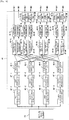
- FIG. 4 is an explanatory diagram for an internal configuration of the left-right picture individual-generation unit 4. This figure additionally shows the picture pickup element 3 and the control unit 7, also.
- the left-right picture individual-generation unit 4 includes a selector 41, a first left-side addition unit 42-1L, a first right-side addition unit 42-1R, a second left-side addition unit 42-2L, a second right-side addition unit 42-2R, a third left-side addition unit 42-3L, a third right-side addition unit 42-3R, a fourth left-side addition unit 42-4L, a fourth right-side addition unit 42-4R, a development processing unit 43-1L, a development processing unit 43-1R, a development processing unit 43-2L, a development processing unit 43-2R, a development processing unit 43-3L, a development processing unit 43-3R, a development processing unit 43-4L, a development processing unit 43-4R, a second rotation processing unit 44-2L, a second rotation processing unit 44-2R, a third rotation processing unit 44-3L, a third rotation processing unit 44-3R, a fourth rotation processing unit 44-4L, and a fourth rotation processing unit 44-4R.
- the selector 41 includes output terminals TL1, TR1, TL2, TR2, TL3, TR3, TL4 and TR4. As shown in the figure, the output terminal TL1 is connected with the first left-side addition unit 42-1L, and the output terminal TR1 is connected with the first right-side addition unit 42-1R.
- the output terminal TL2 is connected with the second left-side addition unit 42-2L
- the output terminal TR2 is connected with the second right-side addition unit 42-2R
- the output terminal TL3 is connected with the third left-side addition unit 42-3L
- the output terminal TR3 is connected with the third right-side addition unit 42-3R
- the output terminal TL4 is connected with the fourth left-side addition unit 42-4L
- the output terminal TR4 is connected with the fourth right-side addition unit 42-4R.
- the selector 41 outputs, on a period t basis, the pickup picture signal Ga input from the picture pickup element 3, from the output terminal T selected in response to the instruction from the control unit 7.
- the control unit 7 makes the selector 41 select the output terminal T for outputting the pickup picture signal Ga, as follows.
- the pickup picture signals Ga1 and Ga2 necessary for obtaining the left-eye picture GL1 are input to the first left-side addition unit 42-1L, and the pickup picture signals Ga3 and Ga4 necessary for obtaining the right-eye picture GR1 are input to the first right-side addition unit 42-1R.
- the pickup picture signals Ga2 and Ga3 necessary for obtaining the left-eye picture GL2 are input to the second left-side addition unit 42-2L, and the pickup picture signals Ga1 and Ga4 necessary for obtaining the right-eye picture GR2 are input to the second right-side addition unit 42-2R.
- the pickup picture signals Ga3 and Ga4 necessary for obtaining the left-eye picture GL3 are input to the third left-side addition unit 42-3L, and the pickup picture signals Ga1 and Ga2 necessary for obtaining the right-eye picture GR3 are input to the third right-side addition unit 42-3R.
- the pickup picture signals Ga1 and Ga4 necessary for obtaining the left-eye picture GL4 are input to the fourth left-side addition unit 42-4L, and the pickup picture signals Ga2 and Ga3 necessary for obtaining the right-eye picture GR4 are input to the fourth right-side addition unit 42-4R.
- Each addition unit 42 adds the respective pickup pictures that are based on the two input pickup picture signals.
- the pickup picture after the addition by the first left-side addition unit 42-1L is supplied to the development processing unit 43-1L
- the pickup picture after the addition by the first right-side addition unit 42-1R is supplied to the development processing unit 43-1R
- the pickup picture after the addition by the second left-side addition unit 42-2L is supplied to the development processing unit 43-2L
- the pickup picture after the addition by the second right-side addition unit 42-2R is supplied to the development processing unit 43-2R
- the pickup picture after the addition by the addition by the third left-side addition unit 42-3L is supplied to the development processing unit 43-3L
- the pickup picture after the addition by the third right-side addition unit 42-3R is supplied to the development processing unit 43-3R
- the pickup picture after the addition by the fourth left-side addition unit 42-4L is supplied to the development processing unit 43-4L
- the pickup picture after the addition by the fourth right-side addition unit 42-4R is supplied to the development processing unit 43-4R.
- Each development processing unit 43 performs a development process for the input pickup picture.
- the development process in the embodiment, in which the RGGB-type picture pickup element 3 is used is a demosaic process for obtaining the respective values of R, G and B at least for each pixel of the picture pickup element 3.
- the demosaic process may be a process in which, for a pixel at a horizontally i-th and vertically j-th position on the picture pickup element 3, the values of the colors other than the color to be light-received by the color filter (wavelength filter) of the pixel are calculated respectively using the values of same-color pixels in the vicinity.
- the pickup picture is obtained as a color picture.
- the pickup picture obtained by the development processing unit 43-1L is output as the left-eye picture GL1. Further, the pickup picture obtained by the development processing unit 43-1R is output as the right-eye picture GR1.
- the pickup picture obtained by the development processing unit 43-2L is supplied to the second rotation processing unit 44-2L
- the pickup picture obtained by the development processing unit 43-2R is supplied to the second rotation processing unit 44-2R
- the pickup picture obtained by the development processing unit 43-3L is supplied to the third rotation processing unit 44-3L
- the pickup picture obtained by the development processing unit 43-3R is supplied to the third rotation processing unit 44-3R
- the pickup picture obtained by the development processing unit 43-4L is supplied to the fourth rotation processing unit 44-4L
- the pickup picture obtained by the development processing unit 43-4R is supplied to the fourth rotation processing unit 44-4R.
- Each rotation processing unit 44 rotates the input pickup picture by a previously determined angle.
- the second rotation processing units 44-2L and 44-2R rotate the input pickup picture by 90 deg.
- the third rotation processing units 44-3L and 44-3R rotate the input pickup picture by 180 deg.
- the fourth rotation processing units 44-4L and 44-4R rotate the input pickup picture by 270 deg.
- the placement angle of the picture pickup element 3 in the direction around the optical axis Ox is set such that the position where the angle direction is 0 deg is the reference position for observation. Therefore, the pickup pictures corresponding to the angle directions other than 0 deg are rotated by angles corresponding to the differences from 0 deg, respectively. Thereby, for the observers at the positions in the angle directions other than 0 deg, it is possible to avoid a situation in which the orientation of the subject X exhibited in the stereoscopic picture does not match the orientation of the subject X when the subject X is actually observed.
- the pickup picture after the rotation process by the second rotation processing unit 44-2L is output as the left-eye picture GL2, and the pickup picture after the rotation process by the second rotation processing unit 44-2R is output as the right-eye picture GR2.
- the pickup picture after the rotation process by the third rotation processing unit 44-3L is output as the left-eye picture GL3, and the pickup picture after the rotation process by the third rotation processing unit 44-3R is output as the right-eye picture GR3.
- the pickup picture after the rotation process by the fourth rotation processing unit 44-4L is output as the left-eye picture GL4, and the pickup picture after the rotation process by the fourth rotation processing unit 44-4R is output as the right-eye picture GR4.
- the stereoscopic picture generation apparatus 1 includes the pupil division unit 22 that the light through the condensing lens 21 condensing light from a photographic subject enters and that has the three or more areas A formed by division in the direction around the optical axis Ox, and a picture selective-acquisition unit (the picture pickup element 3, the selector 41 and the control unit 7) that includes the picture pickup element 3 to form the pictures for the images that has passed through the pupil division unit 22 and that selectively acquires, by time division, the pickup pictures for the respective images that have passed through the different areas A in the pupil division unit 22.
- a picture selective-acquisition unit the picture pickup element 3, the selector 41 and the control unit 7 that includes the picture pickup element 3 to form the pictures for the images that has passed through the pupil division unit 22 and that selectively acquires, by time division, the pickup pictures for the respective images that have passed through the different areas A in the pupil division unit 22.
- the pupil division unit 22 has the areas A the number of which is a multiple of two and four or more
- the stereoscopic picture generation apparatus 1 includes the picture addition units (42-1L to 42-4R) that add the plurality of pickup pictures acquired by the picture selective-acquisition unit, with the different combinations, respectively.
- the picture selective-acquisition unit acquires, by time division, the pickup pictures for the respective images that have passed through the different areas A in the pupil division unit 22, with the picture pickup element 3.
- the picture pickup element 3 does not have to be configured to receive the respective images that have passed through the different areas A, at different positions on the picture pickup surface, leading to a simple configuration and a cost reduction.
- the pupil division unit 22 can allow incident light to pass through the areas A/block incident light for each of the areas A, and the picture selective-acquisition unit sequentially selects the area A through which the incident light is to pass, and sequentially receives the image that has passed through the selected area A, with the picture pickup element 3.
- the pickup pictures for the respective images that have passed through the different areas A are selectively acquired by a simple technique of controlling the passing/blocking of incident light for each of the areas A. Therefore, it is possible to easily implement a stereoscopic picture generation apparatus that properly presents the respective stereoscopic pictures when a subject is observed from different angle directions.
- the stereoscopic picture generation apparatus 1 includes the picture rotation processing units (the second rotation processing unit 44-2L to the fourth rotation processing unit 44-4R) that rotate the left-eye pictures GL and right-eye pictures GR obtained based on the pickup pictures acquired by the picture selective-acquisition unit.
- the picture rotation processing units (the second rotation processing unit 44-2L to the fourth rotation processing unit 44-4R) that rotate the left-eye pictures GL and right-eye pictures GR obtained based on the pickup pictures acquired by the picture selective-acquisition unit.
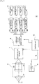
- FIG. 5 is a block diagram showing an internal configuration of a stereoscopic picture generation apparatus 1A according to a second embodiment.
- the stereoscopic picture generation apparatus 1A selectively acquires, by time division, the pickup pictures for the respective images that have passed through the different areas A.
- the stereoscopic picture generation apparatus 1A is different in that an optical unit 2A is provided instead of the optical unit 2, a left-right picture individual-generation unit 4A is provided instead of the left-right picture individual-generation unit 4, a control unit 7A is provided instead of the control unit 7, and an illumination unit 8A is provided instead of the illumination unit 8.
- the optical unit 2A is different from the optical unit 2 in that a pupil division unit 22A is provided instead of the pupil division unit 22.
- the configuration of the pupil division unit 22A will be described later.
- the illumination unit 8A includes a laser drive unit 81 and a plurality of LDs (laser diodes) 82.
- a first red-color LD 82R1, second red-color LD 82R2, third red-color LD 82R3 and fourth red-color LD 82R4 that emit the light with a red-color wavelength band a first green-color LD 82G1, second green-color LD 82G2, third green-color LD 82G3 and fourth green-color LD 82G4 that emit the light with a green-color wavelength band
- a first blue-color LD 82B1, second blue-color LD 82B2, third blue-color LD 82B3 and fourth blue-color LD 82B4 that emit the light with a blue-color wavelength band are included.
- the first red-color LD 82R1, the second red-color LD 82R2, the third red-color LD 82R3 and the fourth red-color LD 82R4 can emit lights with different wavelength bands in the red-color wavelength band, respectively.
- the respective wavelength bands when the red-color wavelength band is divided into four wavelength bands are wavelength bands R1, R2, R3 and R4 as shown in FIG. 6B
- the first red-color LD 82R1 can emit the light with the wavelength band R1
- the second red-color LD 82R2 can emit the light with the wavelength band R2
- the third red-color LD 82R3 can emit the light with the wavelength band R3
- the fourth red-color LD 82R4 can emit the light with the wavelength band R4.
- the green-color LDs 82 and the blue-color LDs 82 can emit lights with different wavelength bands in the respective color wavelength bands.
- the green-color LDs 82 in the case where the respective wavelength bands when the green-color wavelength band is divided into four wavelength bands are wavelength bands G1, G2, G3 and G4 as shown in FIG. 6B , the first green-color LD 82G1 can emit the light with the wavelength band G1, the second green-color LD 82G2 can emit the light with the wavelength band G2, the third green-color LD 82G3 can emit the light with the wavelength band G3, and the fourth green-color LD 82G4 can emit the light with the wavelength band G4.
- the first blue-color LD 82B1 can emit the light with the wavelength band B1
- the second blue-color LD 82B2 can emit the light with the wavelength band B2
- the third blue-color LD 82B3 can emit the light with the wavelength band B3
- the fourth blue-color LD 82B4 can emit the light with the wavelength band B4.
- the laser drive unit 81 drives the emission of an LD 82 designated by an instruction signal SL from the control unit 7A.
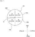
- FIG. 7 is an explanatory diagram for a configuration of the pupil division unit 22A.
- the pupil division unit 22A is viewed from the image surface side.
- the pupil division unit 22A is divided such that the areas A1 to A4 are formed similarly to the pupil division unit 22.
- each of the areas A1 to A4 is configured by a wavelength filter.
- the area A1 is configured by a wavelength filter 22Aa
- the area A2 is configured by a wavelength filter 22Ab
- the area A3 is configured by a wavelength filter 22Ac
- the area A4 is configured by a wavelength filter 22Ad.
- the wavelength filters 22Aa to 22Ad are configured as so-called multiband-pass filters, and selectively transmit lights with three wavelength bands.
- the wavelength filter 22Aa transmits the lights with the wavelength bands R1, G1 and B1
- the wavelength filter 22Ab transmits the lights with the wavelength bands R2, G2 and B2.
- the wavelength filter 22Ac transmits the lights with the wavelength bands R3, G3 and B3, and the wavelength filter 22Ad transmits the lights with the wavelength bands R4, G4 and B4.
- the control unit 7A controls the ON/OFF of the LDs 82 in the illumination unit 8A by the instruction signal SL, as follows. That is, a set of the first red-color LD 82R1, the first green-color LD 82G1 and the first blue-color LD 82B1, a set of the second red-color LD 82R2, the second green-color LD 82G2 and the second blue-color LD 82B2, a set of the third red-color LD 82R3, the third green-color LD 82G3 and the third blue-color LD 82B3, and a set of the fourth red-color LD 82R4, the fourth green-color LD 82G4 and the fourth blue-color LD 82B4 are turned on sequentially and alternately.
- the control unit 7A executes the control of sequentially turning on each set of the LDs 82 in this way, repeatedly in a predetermined cycle.
- the lights with the wavelength bands R1, G1 and B1 the lights with the wavelength bands R2, G2 and B2, the lights with the wavelength bands R3, G3 and B3, and the lights with the wavelength bands R4, G4 and B4 sequentially enter the pupil division unit 22A, as the light from the photographic subject.
- the lights pass through only the area A1.
- the lights with the wavelength bands R2, G2 and B2 enter the pupil division unit 22A the lights pass through only the area A2.
- the lights pass through only the area A3.
- the lights with the wavelength bands R4, G4 and B4 enter the pupil division unit 22A the lights pass through only the area A4.
- the period t1 during which incident light passes through only the area A1 is repeated in a predetermined cycle.
- control unit 7A controls the picture pickup operation of the picture pickup element 3 such that the picture pickup element 3 individually acquires the pickup picture signal in each of the period t1 to the period t4.
- the pickup picture signal Ga1, the pickup picture signal Ga2, the pickup picture signal Ga3 and the pickup picture signal Ga4 are acquired individually in the time axis direction.
- the pickup picture signal Ga1, the pickup picture signal Ga2, the pickup picture signal Ga3 and the pickup picture signal Ga4 are acquired individually in the time axis direction, and therefore, if using the same left-right picture individual-generation unit 4 as the first embodiment, it is possible to present stereoscopic pictures corresponding to the respective angle directions of 0 deg, 90 deg, 180 deg and 270 deg.
- each of the pickup picture signal Ga1, pickup picture signal Ga2, pickup picture signal Ga3 and pickup picture signal Ga4 obtained in the second embodiment lacks color components of predetermined wavelength bands for each of the red-color wavelength band, green-color wavelength band and blue-color wavelength band.
- the pickup picture signal Ga1 lacks the color components of the wavelength bands other than the wavelength bands R1, G1 and B1 and the pickup picture signal Ga2 lacks the color components of the wavelength bands other than the wavelength bands R2, G2 and B2. Further, the pickup picture signal Ga3 lacks the color components of the wavelength bands other than the wavelength bands R3, G3 and B3, and the pickup picture signal Ga4 lacks the color components of the wavelength bands other than the wavelength bands R4, G4 and B4.
- the stereoscopic picture generation apparatus 1A is provided with the left-right picture individual-generation unit 4A shown in FIG. 8 , instead of the left-right picture individual-generation unit 4.
- the left-right picture individual-generation unit 4A is different in that color compensation units 45 are interposed between the selector 41 and the addition units 42, respectively.
- a first left-side color compensation unit 45-1L is interposed between the output terminal TL1 of the selector 41 and the first left-side addition unit 42-1L
- a first right-side color compensation unit 45-1R is interposed between the output terminal TR1 and the first right-side addition unit 42-1R
- a second left-side color compensation unit 45-2L is interposed between the output terminal TL2 and the second left-side addition unit 42-2L
- a second right-side color compensation unit 45-2R is interposed between the output terminal TR2 and the second right-side addition unit 42-2R
- a third left-side color compensation unit 45-3L is interposed between the output terminal TL3 and the third left-side addition unit 42-3L
- a third right-side color compensation unit 45-3R is interposed between the output terminal TR3 and the third right-side addition unit 42-3R
- a fourth left-side color compensation unit 45-4L is interposed between the output terminal TL4 and the fourth left-side addition unit 42-4L
- the control unit 7A performs the same control as the control unit 7, as the selection control of the output terminals T to the selector 41. That is, the type of the pickup picture signals Ga to be output from the respective terminals T of the terminals TL1 to TR4 in the respective periods t of the period t1 to the period t4 is the same as the first embodiment.
- the first left-side color compensation unit 45-1L and the third right-side color compensation unit 45-3R to which only the pickup picture signal Ga1 and the pickup picture signal Ga2 are input, can selectively execute, for the input pickup picture signals Ga, a process to compensate the color components other than the wavelength bands R1, G1 and B1 (hereinafter, referred to as a "for-first-wavelength compensation process") and a process to compensate the color components other than the wavelength bands R2, G2 and B2 (referred to as a "for-second-wavelength compensation process").
- the first right-side color compensation unit 45-1R and the third left-side color compensation unit 45-3L to which only the pickup picture signal Ga3 and the pickup picture signal Ga4 are input, can selectively execute, for the input pickup picture signals Ga, a process to compensate the color components other than the wavelength bands R3, G3 and B3 (referred to as a "for-third-wavelength compensation process") and a process to compensate the color components other than the wavelength bands R4, G4 and B4 (referred to as a "for-fourth-wavelength compensation process").
- the second left-side color compensation unit 45-2L and the fourth right-side color compensation unit 45-4R to which only the pickup picture signal Ga2 and the pickup picture signal Ga3 are input, can selectively execute, for the input pickup picture signals Ga, the for-second-wavelength compensation process and the for-third-wavelength compensation process
- the second right-side color compensation unit 45-2R and the fourth left-side color compensation unit 45-4L to which only the pickup picture signal Ga1 and the pickup picture signal Ga4 are input, can selectively execute, for the input pickup picture signals Ga, the for-first-wavelength compensation process and the for-fourth-wavelength compensation process.
- control unit 7A To the first left-side color compensation unit 45-1L to the fourth right-side color compensation unit 45-4R, the control unit 7A performs such a control that the following compensation processes are executed on a period t basis.
- the stereoscopic picture generation apparatus 1A includes the pupil division unit 22A that the light through the condensing lens 21 condensing light from the photographic subject enters and that has the three or more areas A formed by division in the direction around the optical axis Ox, and a picture selective-acquisition unit (the illumination unit 8A, the picture pickup element 3, the selector 41 and the control unit 7A) that includes the picture pickup element 3 to form the pictures for the images that have passed through the pupil division unit 22A and that selectively acquires, by time division, the pickup pictures for the respective images that have passed through the different areas A in the pupil division unit 22A.
- a picture selective-acquisition unit the illumination unit 8A, the picture pickup element 3, the selector 41 and the control unit 7A
- the picture selective-acquisition unit acquires, by time division, the pickup pictures for the respective images that have passed through the different areas A in the pupil division unit 22A, with the picture pickup element 3. This leads to a simple configuration of the picture pickup element 3 and a cost reduction, similarly to the first embodiment.
- the pupil division unit 22A is configured such that, through the areas A, the lights with the different wavelength bands selectively pass, each of which has the respective wavelength bands of the red-color wavelength band, the green-color wavelength band and the blue-color wavelength band.
- the picture pickup element 3 can receive the lights with the red-color wavelength band, the green-color wavelength band and the blue-color wavelength band.
- the picture selective-acquisition unit includes the variable wavelength illumination unit (illumination unit 8A) that can selectively emit, as illumination light to the photographic subject, the lights with the same wavelength bands respectively as the lights with the wavelength bands to pass through the individual areas A in the pupil division unit 22A, and sequentially emits the lights with the different wavelength bands, with the variable wavelength illumination unit, while sequentially receiving the lights that have passed through the pupil division unit 22A for each switching of the emission wavelengths of the variable wavelength illumination unit, with the picture pickup element 3.
- the variable wavelength illumination unit illumination unit 8A
- the pickup pictures for the respective images that have passed through the different areas A are selectively acquired by the simple technique of switching the emission wavelengths of the variable wavelength illumination unit.
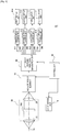
- FIG. 9 is a block diagram showing an internal configuration of a stereoscopic picture generation apparatus 1B according to a third embodiment.
- the stereoscopic picture generation apparatus 1B selectively acquires the pickup pictures for the respective images that have passed through the different areas A, by utilizing the difference in wavelength of the respective images.
- the stereoscopic picture generation apparatus 1B is different in that a picture pickup element 3A is provided instead of the picture pickup element 3, a left-right picture individual-generation unit 4B is provided instead of the left-right picture individual-generation unit 4A, a control unit 7B is provided instead of the control unit 7A, and an illumination unit 8 is provided instead of the illumination unit 8A.
- the control unit 7B controls the picture pickup element 3A such that it sequentially acquires pickup picture signals in a predetermined cycle.
- the illumination unit 8 illuminates the photographic subject, which is the subject X, by white light.
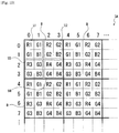
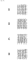
- FIG. 10 is an explanatory diagram for a configuration of the picture pickup element 3A, and shows a part of the picture pickup surface side of the picture pickup element 3A in an enlarged manner.
- the picture pickup element 3A is an RGGB-type picture pickup element.
- the RGGB-type picture pickup element four pixels of horizontally two pixels and vertically two pixels constitute one RGGB unit.
- color filters wavelength filters to selectively transmit the lights with the red wavelength band, the green wavelength band and the blue wavelength band are formed on the upper-left pixel, the upper-right and lower-left pixels and the lower-right pixel, respectively. That is, the upper-left pixel is a red-color pixel, the upper-right and lower-left pixels are green-color pixels, and the lower-right pixel is a blue-color pixel.
- the RGGB units are arrayed horizontally and vertically.
- the picture pickup element 3A includes, as the RGGB unit, four types of RGGB units U1, U2, U3 and U4 that are configured to differ in the transmission wavelength band for each of the red-color wavelength band, green-color wavelength band and blue-color wavelength band.
- blocks B each of which is constituted by these RGGB units U1 to U4 and includes sixteen pixels of horizontally four pixels and vertically four pixels are arrayed horizontally and vertically.
- the RGGB unit U1 is constituted by a pixel that is a red-color pixel and on which a wavelength filter to selectively transmit the light with the wavelength band R1 is formed, a pixel that is a green-color pixel and on which a wavelength filter to selectively transmit the light with the wavelength band G1 is formed, and a pixel that is a blue-color pixel and on which a wavelength filter to selectively transmit the light with the wavelength band B1 is formed.
- the RGGB unit U2 is constituted by a pixel that is a red-color pixel and on which a wavelength filter to selectively transmit the light with the wavelength band R2 is formed, a pixel that is a green-color pixel and on which a wavelength filter to selectively transmit the light with the wavelength band G2 is formed, and a pixel that is a blue-color pixel and on which a wavelength filter to selectively transmit the light with the wavelength band B2 is formed.
- the RGGB unit U3 is constituted by a pixel that is a red-color pixel and on which a wavelength filter to selectively transmit the light with the wavelength band R3 is formed, a pixel that is a green-color pixel and on which a wavelength filter to selectively transmit the light with the wavelength band G3 is formed, and a pixel that is a blue-color pixel and on which a wavelength filter to selectively transmit the light with the wavelength band B3 is formed.
- the RGGB unit U4 is constituted by a pixel that is a red-color pixel and on which a wavelength filter to selectively transmit the light with the wavelength band R4 is formed, a pixel that is a green-color pixel and on which a wavelength filter to selectively transmit the light with the wavelength band G4 is formed, and a pixel that is a blue-color pixel and on which a wavelength filter to selectively transmit the light with the wavelength band B4 is formed.
- the arrangement position relation of the RGGB units U1 to U4 in each block B is common.
- the RGGB unit U1 is positioned at the upper left
- the RGGB unit U2 is positioned at the upper right
- the RGGB unit U3 is positioned at the lower left
- the RGGB unit U4 is positioned at the lower right, in each block B.
- the image that has passed through the area A1 in the pupil division unit 22A is picked up (light-received) by only the RGGB unit U1, and the image that has passed through the area A2 is picked up by only the RGGB unit U2. Further, the image that has passed through the area A3 is picked up by only the RGGB unit U3, and the image that has passed through the area A4 is picked up by only the RGGB unit U4.
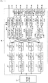
- FIG. 11 is an explanatory diagram for an internal configuration of the left-right picture individual-generation unit 4B.
- the left-right picture individual-generation unit 4B is different in the configuration of the former stage of the first left-side addition unit 42-1L to the fourth right-side addition unit 42-4R, compared to the left-right picture individual-generation unit 4A, and the configuration of the other part is the same as the left-right picture individual-generation unit 4A.
- the pickup picture signals obtained by the picture pickup element 3A are input to a first area-passing-image extraction unit 46-1, a second area-passing-image extraction unit 46-2, a third area-passing-image extraction unit 46-3 and a fourth area-passing-image extraction unit 46-4, respectively.
- Each area-passing-image extraction unit 46 extracts the pixel values at previously determined pixel positions, from the pickup picture based on the pickup picture signal input by the picture pickup element 3A.
- FIG. 12A to FIG. 12D show the respective pixel positions for which the first area-passing-image extraction unit 46-1 to the fourth area-passing-image extraction unit 46-4 perform the extraction, by voids.
- the first area-passing-image extraction unit 46-1 extracts the pixel values at the same pixel positions as the RGGB unit U1 ( FIG. 12A ). Further, the second area-passing-image extraction unit 46-2 extracts the pixel values at the same pixel positions as the RGGB unit U2 ( FIG. 12B ), the third area-passing-image extraction unit 46-3 extracts the pixel values at the same pixel positions as the RGGB unit U3 ( FIG. 12C ), and the fourth area-passing-image extraction unit 46-4 extracts the pixel values at the same pixel positions as the RGGB unit U4 ( FIG. 12D ).
- the "extraction” mentioned here means that the pixel values at the pixel positions other than the intended pixel positions are eliminated from the original pickup picture (for example, "0" is set).
- the pickup picture after the extraction process by the first area-passing-image extraction unit 46-1 is input to a first interpolation processing unit 47-1
- the pickup picture after the extraction process by the second area-passing-image extraction unit 46-2 is input to a second interpolation processing unit 47-2
- the pickup picture after the extraction process by the third area-passing-image extraction unit 46-3 is input to a third interpolation processing unit 47-3
- the pickup picture after the extraction process by the fourth area-passing-image extraction unit 46-4 is input to a fourth interpolation processing unit 47-4.
- each interpolation processing unit 47 interpolates the pixel values at the pixel positions other than the pixel positions for which the pixel values have been extracted.
- the first interpolation processing unit 47-1 interpolates the pixel values at the pixel positions other than the same pixel positions as the RGGB unit U1 based on the pixel values at the same pixel positions as the RGGB unit U1.
- the second interpolation processing unit 47-2 interpolates the pixel values at the pixel positions other than the same pixel positions as the RGGB unit U2 based on the pixel values at the same pixel positions as the RGGB unit U2
- the third interpolation processing unit 47-3 interpolates the pixel values at the pixel positions other than the same pixel positions as the RGGB unit U3 based on the pixel values at the same pixel positions as the RGGB unit U3
- the fourth interpolation processing unit 47-4 interpolates the pixel values at the pixel positions other than the same pixel positions as the RGGB unit U4 based on the pixel values at the same pixel positions as the RGGB unit U4.
- the pickup picture after the interpolation process by the first interpolation processing unit 47-1 is input to a first color compensation unit 48-1
- the pickup picture after the interpolation process by the second interpolation processing unit 47-2 is input to a second color compensation unit 48-2
- the pickup picture after the interpolation process by the third interpolation processing unit 47-3 is input to a third color compensation unit 48-3
- the pickup picture after the interpolation process by the fourth interpolation processing unit 47-4 is input to a fourth color compensation unit 48-4.
- Each color compensation unit 48 executes a process to compensate lacked color components, for the input pickup picture.
- the pickup picture after the extraction process by the first area-passing-image extraction unit 46-1 corresponds to the pickup picture for the image that has passed through the area A1, and therefore, lacks the color components other than the wavelength bands R1, G1 and B1.
- the pickup picture after the extraction process by the second area-passing-image extraction unit 46-2 corresponds to the pickup picture for the image that has passed through the area A2, and therefore, lacks the color components other than the wavelength bands R2, G2 and B2.
- the pickup picture after the extraction process by the third area-passing-image extraction unit 46-3 corresponds to the pickup picture for the image that has passed through the area A3, and therefore, lacks the color components other than the wavelength bands R3, G3 and B3.
- the pickup picture after the extraction process by the fourth area-passing-image extraction unit 46-4 corresponds to the pickup picture for the image that has passed through the area A4, and therefore, lacks the color components other than the wavelength bands R4, G4 and B4.
- the first color compensation unit 48-1 executes the above described for-first-wavelength compensation process for the input pickup picture. Further, the second color compensation unit 48-2 executes the above described for-second-wavelength compensation process for the input pickup picture, the third color compensation unit 48-3 executes the above described for-third-wavelength compensation process for the input pickup picture, and the fourth color compensation unit 48-4 executes the above described for-fourth-wavelength compensation process for the input pickup picture.
- the pickup pictures are input from the two corresponding color compensation units 48 of the first color compensation unit 48-1 to the fourth color compensation unit 48-4.
- the connection relation between the first left-side addition unit 42-1L to the fourth right-side addition unit 42-4R and the first color compensation unit 48-1 to the fourth color compensation unit 48-4 is as follows.
- the pickup pictures are properly added, for each of the left-eye areas and right-eye areas of the respective observers at the positions in the angle directions of 0 deg, 90 deg, 180 deg and 270 deg.
- the stereoscopic picture generation apparatus 1B includes the pupil division unit 22A that the light through the condensing lens 21 condensing light from the photographic subject enters and that has the three or more areas A formed by division in the direction around the optical axis Ox, and a picture selective-acquisition unit (the picture pickup element 3A, and the first area-passing-image extraction unit 46-1 to the fourth area-passing-image extraction unit 46-4) that includes the picture pickup element 3A to form the pictures for the images that have passed through the pupil division unit 22A and that selectively acquires the pickup pictures for the respective images that have passed through the different areas A in the pupil division unit 22A, by utilizing the difference in wavelength of the respective images.
- a picture selective-acquisition unit the picture pickup element 3A, and the first area-passing-image extraction unit 46-1 to the fourth area-passing-image extraction unit 46-4
- the pupil division unit 22A is configured such that the lights with the different wavelength bands selectively pass through the areas A and the picture pickup element 3A arranges, at the different positions on the picture pickup surface, the plurality of the wavelength filters to selectively transmit the lights with the same wavelength bands as the lights that have passed through the different areas A in the pupil division unit 22A, respectively.
- the display period for a single piece of stereoscopic picture that is, the display period for a single piece of left-eye picture GL and a single piece of right-eye picture GR is referred to as the "single-display period".
- the pickup pictures for the images that have passed through the respective areas A can be simultaneously acquired, and therefore, unlike the first and second embodiments, it is not necessary to separate the single-display period into the plurality of periods t. Thereby, it is possible to slow the shutter speed of the picture pickup element 3A, resulting in an advantage when picking up a picture for a dark photographic subject or a fast-moving photographic subject.
- the number of picture pickups by the picture pickup element 3A necessary for presenting a single piece of stereoscopic picture is "1". Therefore, the number of picture pickups by the picture pickup element 3A can be decreased compared to the case of the time division acquisition as the first and second embodiments.
- the pupil division unit 22A is configured such that, through the areas A, the lights with the different wavelength bands selectively pass, each of which has the respective wavelength bands of the red-color wavelength band, the green-color wavelength band and the blue-color wavelength band, and the picture pickup element 3A arranges, at the different positions on the picture pickup surface, the plurality of the wavelength filters to selectively transmit the lights with the same wavelength bands as the lights that have passed through the different areas A in the pupil division unit 22A, respectively.
- the pickup pictures for the images that have passed through the areas A are individually picked up at the different positions on the picture pickup surface, respectively, and therewith, color pictures are obtained as the pickup pictures. Therefore, it is possible to present stereoscopic pictures that have a high visibility due to the color pictures.
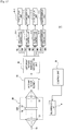
- FIG. 13 is a block diagram showing an internal configuration of a stereoscopic picture generation apparatus 1C according to a fourth embodiment.
- the stereoscopic picture generation apparatus 1C selectively acquires the pickup pictures for the respective images that have passed through the different areas A, by utilizing the difference in wavelength and polarization of the respective images.
- the stereoscopic picture generation apparatus 1C is different in that an optical unit 2B is provided instead of the optical unit 2A, a picture pickup element 3B is provided instead of the picture pickup element 3A, and a left-right picture individual-generation unit 4C is provided instead of the left-right picture individual-generation unit 4B.
- the optical unit 2B is different in that a pupil division unit 22B is provided instead of the pupil division unit 22A.
- the pupil division unit 22B includes a wavelength separation element 24 and a polarization separation element 25. These wavelength separation element 24 and polarization separation element 25 are arranged so as to be overlapped in the optical axis direction. In the embodiment, these wavelength separation element 24 and polarization separation element 25 are bonded so as to be faced.
- the wavelength separation element 24 and the polarization separation element 25 are arranged, in that order, from the photographic subject side to the image surface side, but, the arrangement relation may be reversed.
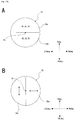
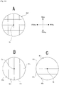
- FIG. 14A is an explanatory diagram for a configuration of the wavelength separation element 24.
- the wavelength separation element 24 includes a wavelength filter 24a that selectively transmits the lights with the wavelength bands R1, G1 and B1, and a wavelength filter 24b that selectively transmits the lights with the wavelength bands R2, G2 and B2.
- the wavelength separation element 24 has two areas partitioned by a single dividing line intersecting with the optical axis Ox.
- the wavelength filter 24a is formed in one area, and the wavelength filter 24b is formed in the other area.
- the dividing line partitioning between the wavelength filter 24a and the wavelength filter 24b is parallel to the 90 deg-270 deg axis. Across this dividing line, the wavelength filter 24a is formed on the 0 deg side, and the wavelength filter 24b is formed on the 180 deg side.
- FIG. 14B is an explanatory diagram for a configuration of the polarization separation element 25.
- the polarization separation element 25 includes a polarizing plate 25a and a polarizing plate 25b.
- the polarization separation element 25 has two areas partitioned by a single dividing line intersecting with the optical axis Ox.
- the polarizing plate 25a is formed in one area, and the polarizing plate 25b is formed in the other area.
- the dividing line partitioning between the polarizing plate 25a and the polarizing plate 25b is parallel to the 0 deg-180 deg axis. Across this dividing line, the polarizing plate 25a is formed on the 90 deg side, and the polarizing plate 25b is formed on the 270 deg side.
- the transmission axis of the polarizing plate 25a is parallel to the 90 deg-270 deg axis. That is, the polarizing plate 25a selectively transmits a linearly-polarized light that is in the polarization direction parallel to the 90 deg-270 deg axis.
- the transmission axis of the polarizing plate 25b is parallel to the 0 deg-180 deg axis, and the polarizing plate 25b selectively transmits a linearly-polarized light that is in the polarization direction parallel to the 0 deg-180 deg axis.
- the polarization direction parallel to the 90 deg-270 deg axis is referred to as the "first polarization direction”
- the polarization direction parallel to the 0 deg-180 deg axis is referred to as the "second polarization direction”.
- the pupil division unit 22B is divided into four areas A, by each dividing line of the wavelength separation element 24 and the polarization separation element 25.
- an area A of 0 deg to 90 deg is referred to as an "area A1”
- an area A of 90 deg to 180 deg is referred to as an "area A2”
- an area A of 180 deg to 270 deg is referred to as an "area A3”
- an area A of 270 deg to 0 deg (360 deg) is referred to as an "area A4".
- the area A1 is an area A that transmits the light by the combination of the wavelength bands R1, G1 and B1 and the first polarization direction, as the combination of the wavelength band and the polarization.
- the area A2 is an area A that transmits the light by the combination of the wavelength bands R2, G2 and B2 and the first polarization direction
- the area A3 is an area A that transmits the light by the combination of the wavelength bands R2, G2 and B2 and the second polarization direction
- the area A4 is an area A that transmits the light by the combination of the wavelength bands R1, G1 and B1 and the second polarization direction.
- FIG. 15 is an explanatory diagram for a configuration of the picture pickup element 3B.
- the horizontal pixel number is represented by n
- the vertical pixel number is represented by m.
- the picture pickup element 3B includes a plurality of wavelength filters (image-surface-side wavelength filters) that selectively transmit the lights with the same wavelength bands as the lights that have passed through the wavelength filters 24a and 24b, respectively, and polarizing plates 3Ba and 3Bb (image-surface-side polarizing plates) that selectively transmit the polarized lights in the same polarization direction as the polarized lights that have passed through the polarizing plates 25a and 25b, respectively.
- wavelength filters image-surface-side wavelength filters
- polarizing plates 3Ba and 3Bb image-surface-side polarizing plates
- the polarizing plate 3Ba that selectively transmits the polarized light in the first polarization direction, and the polarizing plate 3Bb that selectively transmits the polarized light in the second polarization direction are arranged alternately on a two-horizontal-line basis.
- Each of the polarizing plate 3Ba and the polarizing plate 3Bb is formed so as to cover the respective wavelength filters formed on the RGGB units U1 and U2. That is, the polarizing plate 3Ba and the polarizing plate 3Bb are arranged so as to be overlapped with these wavelength filters, in the optical axis direction.
- the respective types of wavelength filters formed on the RGGB units U1 and U2 and the polarizing plates 3Ba and 3Bb are arranged in different combination at different positions on the surface parallel to the picture pickup surface, respectively, so as to be overlapped in the optical axis direction.
- the polarizing plate 3Ba is overlapped with the RGGB unit U1
- These parts are, in the same order, a part through which the light by the same combination of the wavelength and the polarization as the light that has passed through the area A1 passes, a part through which the light by the same combination of the wavelength and the polarization as the light that has passed through the area A2 passes, a part through which the light by the same combination of the wavelength and the polarization as the light that has passed through the area A3 passes, and a part through which the light by the same combination of the wavelength and the polarization as the light that has passed through the area A4 passes.
- the images that have passed through the areas A in the pupil division unit 22B are individually picked up at the different positions on the picture pickup surface, respectively.
- FIG. 16 is an explanatory diagram for an internal configuration of the left-right picture individual-generation unit 4C.
- the left-right picture individual-generation unit 4C is different in the configuration of the former stage of the first left-side addition unit 42-1L to the fourth right-side addition unit 42-4R, compared to the left-right picture individual-generation unit 4B.
- the configuration of the other part is the same as the left-right picture individual-generation unit 4B.
- the pickup picture signals obtained by the picture pickup element 3B are input to a first area-passing-image extraction unit 46'-1, a second area-passing-image extraction unit 46'-2, a third area-passing-image extraction unit 46'-3, and a fourth area-passing-image extraction unit 46'-4.
- Each area-passing-image extraction unit 46' extracts the pixel values at previously determined pixel positions, from the pickup picture based on the pickup picture signal input by the picture pickup element 3B.
- FIG. 17A to FIG. 17D show the respective pixel positions for which the first area-passing-image extraction unit 46'-1 to the fourth area-passing-image extraction unit 46'-4 perform the extraction, by voids.
- the first area-passing-image extraction unit 46'-1 extracts the pixel values at the same pixel positions as the RGGB unit U1 with which the polarizing plate 3Ba is overlapped ( FIG. 17A ).
- the second area-passing-image extraction unit 46'-2 extracts the pixel values at the same pixel positions as the RGGB unit U2 with which the polarizing plate 3Ba is overlapped ( FIG.
- the third area-passing-image extraction unit 46'-3 extracts the pixel values at the same pixel positions as the RGGB unit U2 with which the polarizing plate 3Bb is overlapped ( FIG. 17C ), and the fourth area-passing-image extraction unit 46'-4 extracts the pixel values at the same pixel positions as the RGGB unit U1 with which the polarizing plate 3Bb is overlapped ( FIG. 17D ).
- the pickup picture after the extraction process by the first area-passing-image extraction unit 46'-1 is input to a first interpolation processing unit 47'-1
- the pickup picture after the extraction process by the second area-passing-image extraction unit 46'-2 is input to a second interpolation processing unit 47'-2
- the pickup picture after the extraction process by the third area-passing-image extraction unit 46'-3 is input to a third interpolation processing unit 47'-3
- the pickup picture after the extraction process by the fourth area-passing-image extraction unit 46'-4 is input to a fourth interpolation processing unit 47'-4.
- each interpolation processing unit 47' interpolates the pixel values at the pixel positions other than the pixel positions for which the pixel values have been extracted. That is, the first interpolation processing unit 47'-1 interpolates the pixel values at the pixel positions other than the same pixel positions as the RGGB unit U1 with which the polarizing plate 3Ba is overlapped, based on the pixel values at the same pixel positions as the RGGB unit U1.
- the second interpolation processing unit 47'-2 interpolates the pixel values at the pixel positions other than the same pixel positions as the RGGB unit U2 with which the polarizing plate 3Ba is overlapped, based on the pixel values at the same pixel positions as the RGGB unit U2.
- the third interpolation processing unit 47'-3 interpolates the pixel values at the pixel positions other than the same pixel positions as the RGGB unit U2 with which the polarizing plate 3Bb is overlapped, based on the pixel values at the same pixel positions as the RGGB unit U2.
- the fourth interpolation processing unit 47'-4 interpolates the pixel values at the pixel positions other than the same pixel positions as the RGGB unit U1 with which the polarizing plate 3Bb is overlapped, based on the pixel values at the same pixel positions as the RGGB unit U1.
- the left-right picture individual-generation unit 4C is provided with only two types of color compensation units 48: a first color compensation unit 48-1 corresponding to the RGGB unit U1 and a second color compensation unit 48-2 corresponding to the RGGB unit U2.
- the pickup picture after the interpolation process by the first interpolation processing unit 47'-1 is input to one first color compensation unit 48-1
- the pickup picture after the interpolation process by the second interpolation processing unit 47'-2 is input to one second color compensation unit 48-2
- the pickup picture after the interpolation process by the third interpolation processing unit 47'-3 is input to the other second color compensation unit 48-2
- the pickup picture after the interpolation process by the fourth interpolation processing unit 47'-4 is input to the other first color compensation unit 48-1.
- the one first color compensation unit 48-1 compensates the color components lacked by passage through the area A1
- the one second color compensation unit 48-2 compensates the color components lacked by passage through the area A2.
- the other second color compensation unit 48-2 compensates the color components lacked by passage through the area A3, and the other first color compensation unit 48-1 compensates the color components lacked by passage through the area A4.
- the pickup pictures are input from the two corresponding color compensation units 48 of the four color compensation units 48, which includes the above two first color compensation units 48-1 and two second color compensation units 48-2. Concretely, the pickup pictures are input in accordance with the following correspondence relation.
- the stereoscopic picture generation apparatus 1C includes the pupil division unit 22B that the light through the condensing lens 21 condensing light from the photographic subject enters and that has the three or more areas A formed by division in the direction around the optical axis Ox, and a picture selective-acquisition unit (the picture pickup element 3B, and the first area-passing-image extraction unit 46'-1 to the fourth area-passing-image extraction unit 46'-4) that includes the picture pickup element 3B to form the pictures for the images that have passed through the pupil division unit 22B and that selectively acquires the pickup pictures for the respective images that have passed through the different areas A in the pupil division unit 22B, by utilizing the difference in wavelength and polarization of the respective images.
- a picture selective-acquisition unit the picture pickup element 3B, and the first area-passing-image extraction unit 46'-1 to the fourth area-passing-image extraction unit 46'-4
- the area A is divided by utilizing difference in polarization as well as wavelength, and thereby, the type of wavelengths to be used is reduced.
- many types of separation wavelengths make the production of wavelength filters difficult.
- the stereoscopic picture generation apparatus 1C according to the fourth embodiment which reduces the type of wavelength to be used, it is possible to improve the ease of production of the wavelength filters to be used in the pupil division unit 22B.
- the pupil division unit 22B includes the wavelength separation element 24 that forms thereon the plurality of pupil-side wavelength filters (24a, 24b) to selectively transmit lights with different wavelength bands respectively, each of which has the respective wavelength bands of the red-color wavelength band, the green-color wavelength band and the blue-color wavelength band, and the polarization separation element 25 that forms thereon the plurality of pupil-side polarizing plates (25a, 25b) to selectively transmit the different polarized lights respectively.
- the wavelength separation element 24 and the polarization separation element 25 are arranged so as to be overlapped in the optical axis direction, and selectively transmit the lights with the different combinations of the wavelength bands and the polarizations for each of the areas A.
- the picture pickup element 3B includes the plurality of the image-surface-side wavelength filters (the wavelength filters formed on the RGGB units U1 and U2 respectively) to selectively transmit the lights with the same wavelength bands as the lights that have passed through the different pupil-side wavelength filters respectively, and the plurality of the image-surface-side polarizing plates (3Ba, 3Bb) to selectively transmit the polarized lights in the same polarization directions as the polarized lights that have passed through the different pupil-side polarizing plates respectively.
- the image-surface-side wavelength filters and the image-surface-side polarizing plates are arranged with the different combinations at the different positions on the surface parallel to the picture pickup surface, respectively, so as to be overlapped in the optical axis direction.
- the images that have passed through the areas A are individually picked up at the different positions on the picture pickup surface, respectively. Further, as the pickup pictures for the images that have passed through the respective areas A, color pictures are obtained. Thereby, it is possible to simultaneously acquire the pickup pictures for the images that have passed through the respective areas A, and to provide stereoscopic pictures that have a high visibility due to the color pictures.
- FIG. 18 is a block diagram showing an internal configuration of a stereoscopic picture generation apparatus 1D according to a fifth embodiment.
- the angle direction of the position of each observer is not fixed, and the movement of the observer is allowable.
- the third display unit 6-3 and the fourth display unit 6-4 are omitted, and only the first display unit 6-1 and the second display unit 6-2 are provided.
- These first display unit 6-1 and second display unit 6-2 are attached in a rotatable manner in the stereoscopic picture generation apparatus ID, such that the angle direction in which the display surface is oriented can be changed.
- the first display unit 6-1 and the second display unit 6-2 are attached so as to be rotatable around a mirror body in which an optical unit 2' described later is incorporated.
- the stereoscopic picture generation apparatus 1D is different in that the optical unit 2' is provided instead of the optical unit 2, a left-right picture individual-generation unit 4D is provided instead of the left-right picture individual-generation unit 4, and a control unit 7C is provided instead of the control unit 7, and further, is different in that the third display control unit 5-3 and the fourth display control unit 5-4 are omitted in connection with the omission of the third display unit 6-3 and the fourth display unit 6-4, and in that a memory 9 is added.
- the optical unit 2' is provided with a pupil division unit 22', instead of the pupil division unit 22 in the optical unit 2.
- the memory 9 is a readable memory for the control unit 7C, and stores a control table 9a.
- the control table 9a will be described later.
- FIG. 19A is an explanatory diagram for a configuration of the pupil division unit 22'.
- the pupil division unit 22' in which a plurality of areas A are formed by division in the direction around the optical axis Ox, can allow incident light to pass through the areas A/block incident light for each of the areas A, similarly to the pupil division unit 22, but is different in that the division number of the areas A is "8".
- the pupil division unit 22' is divided, by four dividing lines that intersect with the optical axis Ox, so that eight areas A are formed.
- the dividing lines are parallel to the 0 deg-180 deg axis, the 45 deg-225 deg axis, the 90 deg-270 deg axis, and the 135 deg-315 deg axis, respectively, so that the eight area A are even areas.
- an area A of 0 deg to 45 deg is referred to as an "area A1”
- an area A of 45 deg to 90 deg is referred to as an "area A2”
- an area A of 90 deg to 135 deg is referred to as an "area A3”
- an area A of 135 deg to 180 deg is referred to as an "area A4"
- an area A of 180 deg to 225 deg is referred to as an "area A5"
- an area A of 225 deg to 270 deg is referred to as an "area A6”
- an area A of 270 deg to 315 deg is referred to as an "area A7”
- an area A of 315 deg to 0 deg is referred to as an "area A8".
- first electronic shutter 22'a a "first electronic shutter 22'a”
- second electronic shutter 22'b a "third electronic shutter 22'c”
- fourth electronic shutter 22'd a "fifth electronic shutter 22'e”
- sixthth electronic shutter 22'f a "seventh electronic shutter 22'g”
- fifth electronic shutter 22'h a "eighth electronic shutter 22'h”
- the opening/closing control of the first electronic shutter 22'a to the eighth electronic shutter 22'h in the pupil division unit 22' is performed by the control unit 7C.
- FIG. 19B is an explanatory diagram for the movable range of the observer.
- the solid-line arrow denotes the movable range of one observer to which the stereoscopic picture is presented by the first display unit 6-1
- the wavy-line arrow denotes the movable range of the other observer to which the stereoscopic picture is presented by the second display unit 6-2.
- the rotatable range of the first display unit 6-1 is a range of 180 deg that is clockwise from the angle direction of 270 deg to the angle direction of 90 deg.
- the rotatable range of the second display unit 6-2 is a range of 180 deg that is similarly clockwise from the angle direction of 90 deg to the angle direction of 270 deg.
- the angle directions in which the stereoscopic pictures can be properly presented are eight angle directions of 0 deg, 45 deg, 90 deg, 135 deg, 180 deg, 225 deg, 270 deg and 315 deg, which are the same as the respective angle directions of the orientations of the dividing lines in the pupil division unit 22'.
- FIG. 20 is an explanatory diagram for an internal configuration of the left-right picture individual-generation unit 4D.
- FIG. 20 shows the pupil division unit 22', the picture pickup element 3, the control unit 7C and the memory 9, additionally.
- the left-right picture individual-generation unit 4D is different in that a selector 41' is provided instead of the selector 41, and in that a first left-side addition unit 42'-1L is provided instead of the first left-side addition unit 42-1L, a first right-side addition unit 42'-1R is provided instead of the first right-side addition unit 42-1R, a second left-side addition unit 42'-2L is provided instead of the second left-side addition unit 42-2L, and a second right-side addition unit 42'-2R is provided instead of the second right-side addition unit 42-2R.
- the selector 41' is the same as the selector 41, except that the output terminals TL3 to TR4 are omitted.
- the output terminal TL1 of the selector 41' is connected with the first left-side addition unit 42'-1L, the output terminal TR1 is connected with the first right-side addition unit 42'-1R, the output terminal TL2 is connected with the second left-side addition unit 42'-2L, and the output terminal TR2 is connected with the second right-side addition unit 42'-2R.
- Each addition unit 42' outputs the pickup picture after the addition, at the timing of response to an instruction from the control unit 7C.
- Each rotation processing unit 44' rotates the input pickup picture by a rotation angle of an instruction by the control unit 7C.
- the information indicating the angle directions of the positions of the observers is input by a signal Sa1 and a signal Sa2.
- These signals Sa1 and Sa2 may be signals that are obtained by the operation input of the observer through the operation unit, which is omitted in the figure, or may be signals that are obtained by the detection with a detection unit, which is provided to detect the rotation angles of the first display unit 6-1 and the second display unit 6-2.
- the control unit 7C instructs the first rotation processing unit 44'-1L to the second rotation processing unit 44'-2R on the rotation angle of the picture.
- the placement angle of the picture pickup element 3 in the direction around the optical axis Ox is set such that the position where the angle direction is 0 deg is the reference position for observation.
- control unit 7C instructs the first rotation processing unit 44'-1L and the first rotation processing unit 44'-1R on a rotation angle that is the same angle deg as the angle deg of the angle direction given by the signal Sa1, and instructs the second rotation processing unit 44'-2L and the second rotation processing unit 44'-2R on a rotation angle that is the same angle deg as the angle deg of the angle direction given by the signal Sa2.
- control unit 7C performs the shutter control of the pupil division unit 22', the control of the pickup timing of the picture pickup element 3, the selection control of the output terminals T of the selector 41', and the control of the picture output timing of the first left-side addition unit 42-1L to the second right-side addition unit 42-2R.
- the pickup pictures for the images that have passed through the individual areas A that constitute the pupil division unit 22' are acquired individually on the time axis, and then the acquired pickup pictures are added for each of the left-eye areas and right-eye areas corresponding to the angle directions of the positions of the observers.
- the fifth embodiment achieves a reduction in the number of picture pickups by allowing light to simultaneously pass through the plurality of areas A.
- FIG. 21 is an explanatory diagram for combinations of the areas A through which light can simultaneously pass.
- FIG. 21A, FIG. 21B and FIG. 21C exemplify the cases where the combination between the angle direction of the position of the one observer and the angle direction of the position of the other observer is "0 deg, 135 deg", "315 deg, 225 deg” and "0 deg, 180 deg", respectively.
- the left-eye area and right-eye area for the one observer at the position of 0 deg are split by the 0 deg-180 deg axis, the left-eye area is the areas A1 to A4 and the right-eye area is the areas A5 to A8. Further, since the left-eye area and right-eye area for the other observer at the position of 135 deg are split by the 135 deg-315 deg axis, the left-eye area is the areas A4 to A7 and the right-eye area is the areas A8 to A3.
- an overlapped part (A1 to A3) appears between the left-eye area (A1 to A4) for the one observer and the right-eye area (A8 to A3) for the other observer. Further, an overlapped part (A5 to A7) appears between the right-eye area (A5 to A8) for the one observer and the left-eye area (A4 to A7) for the other observer.
- the picture pickup element 3 does not simultaneously pick up the images that have passed through the areas A constituting the left-eye area for the observer and the images that have passed through the areas A constituting the right-eye area for the observer (for preventing the crosstalk between the left-eye side and the right-eye side).
- the picture pickup element 3 does not simultaneously pick up the images that have passed through the areas A constituting the right-eye area for the observer and the images that have passed through the areas A constituting the left-eye area for the observer.
- the left-eye areas and right-eye areas of the above overlapped parts fall within the left-eye areas and right-eye areas for the observers, respectively. Therefore, as for the areas A constituting the overlapped parts, the light can simultaneously pass, when properly obtaining the left-eye picture GL and right-eye picture GR for each observer.
- the light can simultaneously pass. That is, in the area A corresponding to the overlapped parts, the electronic shutters can be simultaneously opened.
- the single-display period is divided into four periods t1 to t4, then, for example, in the period t1, only the first electronic shutter 22'a, second electronic shutter 22'b and third electronic shutter 22'c formed on the areas A1, A2 and A3 are opened, and in the period t2, only the fourth electronic shutter 22'd formed on the area A4 is opened. Further, in the period t3, only the fifth electronic shutter 22'e, sixth electronic shutter 22'f and seventh electronic shutter 22'g formed on the areas A5, A6 and A7 are opened, and in the period t4, only the eighth electronic shutter 22'h formed on the area A8 is opened.
- the following selection control of the output terminals T of the selector 41' is performed, and thereby, the left-eye picture GL and the right-eye picture GR can be properly generated for each observer.
- the single-display period is divided into the periods t1 to t4, then, for example, in the period t1, only the first electronic shutter 22'a and eighth electronic shutter 22'h formed on the areas A1 and A8 are opened.
- the period t2 only the second electronic shutter 22'b and third electronic shutter 22'c formed on the areas A2 and A3 are opened.
- the period t3 only the fourth electronic shutter 22'd and fifth electronic shutter 22'e formed on the areas A4 and A5 are opened.
- only the sixth electronic shutter 22'f and seventh electronic shutter 22'g formed on the areas A6 and A7 are opened.
- the following selection control of the output terminals T of the selector 41' is performed, and thereby, the left-eye picture GL and the right-eye picture GR can be properly generated for each observer.
- the division number of the single-display period is only two: the period t1 and the period t2.
- the period t1 only the first electronic shutter 22'a to the fourth electronic shutter 22'd formed on the areas A1 to A4 are opened, and in the period t2, only the fifth electronic shutter 22'e to the eighth electronic shutter 22'h formed on the areas A5 to A8 are opened.
- the following selection control of the output terminals T of the selector 41' is performed, and thereby, the left-eye picture GL and the right-eye picture GR can be properly generated for each observer.
- the case where the division number of the single-display period is only "2" as FIG. 21C is the case where the angle difference between the angle directions at the positions of the respective observers is 180 deg. In other words, the division number of the single-display period is "4", in the other cases.
- control table 9a the following information is stored for each combination of the angle directions of the positions of the observers.
- the control unit 7C performs the shutter control of the pupil division unit 22', the control of the pickup timing of the picture pickup element 3, the selection control of the output terminals T of the selector 41', and the control of the picture output timing of the first left-side addition unit 42-1L to the second right-side addition unit 42-2R, based on the information of the above a) to c) stored in the control table 9a.
- the control of the pickup timing of the picture pickup element 3 and the control of the picture output timing of the first left-side addition unit 42-1L to the second right-side addition unit 42-2R are performed based on the information of the above a).
- the pupil division unit 22' has the areas A the number of which is a multiple of two and four or more. Further, the stereoscopic picture generation apparatus 1D includes the control unit 7C that, based on the information about the angle directions of the respective positions of the plurality of observers, performs such a control that incident light simultaneously passes through the plurality of areas A, which are of the areas A in the pupil division unit 22' and correspond to the overlapped parts between the one-eye areas for the observers.
- the division number of the areas A is "8" as the embodiment, if the number of the observers (the display units 6) is "6" or less, an overlapped area between one-eye areas for the observers can appear.
- the control according to the fifth embodiment can be performed, if the number of the display units 6 is "6" or less in the case where the division number of the areas A is "8", or if the number of the display units 6 is "2" or less in the case where the division number of the areas A is "4".
- the control according to the fifth embodiment can be performed.
- the information of the correspondence relation between the period t and the LD 82 to emit light is stored in the control table 9a, instead of the information of the above described b) (the information of the correspondence relation between the period t and the area A to be opened).
- FIG. 22 is a block diagram showing an internal configuration of a stereoscopic picture generation apparatus IE according to a sixth embodiment.
- the sixth embodiment relates to the adjustment of a parallax.
- the stereoscopic picture generation apparatus IE is different in that an optical unit 2C is provided instead of the optical unit 2, and a control unit 7D is provided instead of the control unit 7.
- the optical unit 2C is different in that a pupil division unit 22C is provided instead of the pupil division unit 22.
- FIG. 23 is an explanatory diagram for a configuration of the pupil division unit 22C.
- the area A is further divided in the radial direction.
- each of the areas A1, A2, A3 and A4 in the pupil division unit 22 is divided into two in the radial direction.
- the area A1i the inner area nearer to the optical axis Ox
- the outer area is referred to as the "area A1o”.
- the inner area in the area A2 is referred to as the "area A2i”
- the outer area is referred to as the "area A2o”.
- the inner area in the area A3 is referred to as the "area A3i”
- the outer area is referred to as the "area A3o”.
- the inner area in the area A4 is referred to as the "area A4i", and the outer area is referred to as the "area A4o".
- an electronic shutter is formed in each of these areas A.
- the electronic shutters formed on the area A1i and area A1o are referred to as the “first inner electronic shutter 22Cai” and “first outer electronic shutter 22Cao", respectively.
- the electronic shutters formed on the area A2i and area A2o are referred to as the “second inner electronic shutter 22Cbi” and “second outer electronic shutter 22Cbo", respectively.
- the electronic shutters formed on the area A3i and area A3o are referred to as the "third inner electronic shutter 22Cci” and “third outer electronic shutter 22Cco", respectively.
- the electronic shutters formed on the area A4i and area A4o are referred to as the "fourth inner electronic shutter 22Cdi” and “fourth outer electronic shutter 22Cdo", respectively.
- an instruction of a parallax is performed by a signal Ss.
- the instruction of the parallax is performed by an operation input of the observer, and the signal Ss is an operation input signal from an operation unit, which is omitted in the figure.
- the instruction of the parallax is performed by two levels of "large” and "small”.
- the effect by the parallax adjustment is provided to the respective observers (the respective display units 6) in common.
- control unit 7D In response to an instruction of the "large" as the parallax, the control unit 7D performs such a control that the first outer electronic shutter 22Cao, second outer electronic shutter 22Cbo, third outer electronic shutter 22Cco and fourth outer electronic shutter 22Cdo formed on the areas A1o, A2o, A3o and A4o that are the outer areas of the areas A are closed sequentially and alternately.
- the images that have passed through the area A1o and area A2o are used for generating the left-eye picture GL, and the images that have passed through the area A3o and area A4o are used for generating the right-eye picture GR.
- the viewpoint centroid on the left-eye side which is within the area formed by the area A1o and the area A2o, is at a relatively outer position to the optical axis Ox.
- the viewpoint centroid on the right-eye side which is within the area formed by the area A3o and the area A4o, is at a relatively outer position to the optical axis Ox, similarly.
- the images that have passed through the area A1i and area A2i are used for generating the left-eye picture GL, and the images that have passed through the area A3i and area A4i are used for generating the right-eye picture GR.
- the viewpoint centroid on the left-eye side which is within the area formed by the area A1i and the area A2i, is at a relatively inner position to the optical axis Ox.
- the viewpoint centroid on the right-eye side, which is within the area formed by the area A3i and the area A4i is at a relatively inner position to the optical axis Ox, similarly.
- the parallax is adjusted by the two levels.
- the parallax can be adjusted by three levels.
- the viewpoint centroids on the left-eye side and the right-eye side are at nearly middle positions between those when selecting only the outer areas and those when selecting only the inner areas.
- a pupil division unit 22C' whose area is divided in a reticular pattern is used.
- the area is divided by three dividing lines parallel to the 0 deg-180 deg axis and three dividing lines parallel to the 90 deg-270 deg axis, and "16" areas are formed by the division.
- the lines at the respective center positions intersect with the optical axis Ox.
- lines configured by the plurality of areas that are arrayed in the direction parallel to the 0 deg-180 deg axis are referred to as "vertical lines V"
- lines configured by the plurality of areas that are arrayed in the direction parallel to the 90 deg-270 deg axis are referred to as "horizontal lines H”.
- the vertical lines V are referred to as a "vertical line V1o", a “vertical line V1i”, a “vertical line V2i” and a “vertical line V2o", in the order from the angle direction of 90 deg to the angle direction of 270 deg.
- the horizontal lines H are referred to as a "horizontal line H1o", a “horizontal line H1i”, a “horizontal line H2i” and a “horizontal line H2o", in the order from the angle direction of 0 deg to the angle direction of 180 deg.
- the electronic shutters formed on the respective areas in the pupil division unit 22'C are controlled in response to the instruction of the "large" or "small” parallax, as follows.
- the selection control of the output terminals T of the selector 41 is performed as follows.
- the areas A in the pupil division unit 22C are further divided in the radial direction of the pupil division unit 22C, and a picture selective-acquisition unit (the picture pickup element 3 and the control unit 7) selects one or a plurality of areas A from the areas A arrayed in the radial direction in the pupil division unit 22C, and acquires the pickup picture for the image that have passed through the selected area A.
- a picture selective-acquisition unit selects one or a plurality of areas A from the areas A arrayed in the radial direction in the pupil division unit 22C, and acquires the pickup picture for the image that have passed through the selected area A.
- the parallax adjustment according to the sixth embodiment can be applied to the second to fifth embodiments, also.
- FIG. 25A exemplifies the case where three areas A (referred to as A1 to A3) are formed by division in the direction around the optical axis Ox. In this case, the areas A1 to A3 are arranged at intervals of 120 deg.
- the areas A1 and A3 correspond to the left-eye area and right-eye area of the observer at the position in the angle direction of 0 deg respectively
- the areas A1 and A2 correspond to the right-eye area and left-eye area of the observer at the position in the angle direction of 120 deg respectively
- the areas A2 and A3 correspond to the right-eye area and left-eye area of the observer at the position in the angle direction of 240 deg respectively.
- the pupil division unit in which the three areas A are formed by division in the direction around the optical axis Ox the left-eye picture GL and the right-eye picture GR can be properly generated for each of the three angle directions.
- FIG. 25B exemplifies the case where five areas A (referred to as A1 to A5) are formed by division in the direction around the optical axis Ox.
- the areas A1 to A5 are arranged at intervals of 72 deg.
- the left-eye picture GL and the right-eye picture GR can be properly generated for each of the angle directions of 0 deg, 72 deg, 144 deg, 216 deg and 288 deg. That is, in the case where the pupil division unit in which the five areas A are formed by division in the direction around the optical axis Ox is used, the left-eye picture GL and the right-eye picture GR can be properly generated for each of the five angle directions.
- the division number of the areas in the pupil division unit only has to be three or more, and does not have to be a multiple of two.
- the configuration in which the selective emission of the plurality of LDs to emit the lights with the different wavelengths respectively is performed has been exemplified, but it is possible to be a configuration using a light source that can change the emission wavelength by the control of the drive current, for example, a variable wavelength LD. Further, as the light source of the illumination unit 8A, another light-emitting element such as an LED (light emitting diode) can be used.
- the acquisition of the information about the angle directions may be performed by the automatic detection using cameras, for example.
- the present technology can be suitably applied also to another optical product, for example, an endoscope.
- present technology may be configured as described below.
- present technology may also be configured as below.
Landscapes
- Engineering & Computer Science (AREA)
- Multimedia (AREA)
- Signal Processing (AREA)
- Physics & Mathematics (AREA)
- Health & Medical Sciences (AREA)
- Life Sciences & Earth Sciences (AREA)
- Surgery (AREA)
- Optics & Photonics (AREA)
- General Health & Medical Sciences (AREA)
- General Physics & Mathematics (AREA)
- Analytical Chemistry (AREA)
- Chemical & Material Sciences (AREA)
- Biomedical Technology (AREA)
- Veterinary Medicine (AREA)
- Medical Informatics (AREA)
- Molecular Biology (AREA)
- Animal Behavior & Ethology (AREA)
- Radiology & Medical Imaging (AREA)
- Public Health (AREA)
- Heart & Thoracic Surgery (AREA)
- Pathology (AREA)
- Nuclear Medicine, Radiotherapy & Molecular Imaging (AREA)
- Biophysics (AREA)
- Spectroscopy & Molecular Physics (AREA)
- Testing, Inspecting, Measuring Of Stereoscopic Televisions And Televisions (AREA)
- Stereoscopic And Panoramic Photography (AREA)
Applications Claiming Priority (2)
| Application Number | Priority Date | Filing Date | Title |
|---|---|---|---|
| JP2013188377A JP6248484B2 (ja) | 2013-09-11 | 2013-09-11 | 立体視画像生成装置、立体視画像生成方法 |
| PCT/JP2014/004193 WO2015037185A1 (en) | 2013-09-11 | 2014-08-14 | Stereoscopic picture generation apparatus and stereoscopic picture generation method |
Publications (2)
| Publication Number | Publication Date |
|---|---|
| EP3000230A1 EP3000230A1 (en) | 2016-03-30 |
| EP3000230B1 true EP3000230B1 (en) | 2018-10-10 |
Family
ID=51535484
Family Applications (1)
| Application Number | Title | Priority Date | Filing Date |
|---|---|---|---|
| EP14762101.5A Not-in-force EP3000230B1 (en) | 2013-09-11 | 2014-08-14 | Stereoscopic picture generation apparatus and stereoscopic picture generation method |
Country Status (5)
| Country | Link |
|---|---|
| US (1) | US10574968B2 (enExample) |
| EP (1) | EP3000230B1 (enExample) |
| JP (1) | JP6248484B2 (enExample) |
| CN (1) | CN105493504B (enExample) |
| WO (1) | WO2015037185A1 (enExample) |
Families Citing this family (6)
| Publication number | Priority date | Publication date | Assignee | Title |
|---|---|---|---|---|
| CN108697123B (zh) * | 2016-02-12 | 2023-02-28 | 日本史迪士生物科学株式会社 | 功能性饲料 |
| WO2018193544A1 (ja) * | 2017-04-19 | 2018-10-25 | オリンパス株式会社 | 撮像装置および内視鏡装置 |
| JP7238121B2 (ja) * | 2019-06-11 | 2023-03-13 | 富士フイルム株式会社 | 撮像装置 |
| EP3772852A1 (en) * | 2019-08-06 | 2021-02-10 | Leica Instruments (Singapore) Pte. Ltd. | Optical assembly, image processing apparatus and method for recording and/or retrieving a stereoscopic color image with multiple stereoscopic channels in a multispectral color image |
| EP4003155B1 (en) * | 2019-09-02 | 2025-10-29 | Canfield Scientific, Incorporated | Variable polarization and skin depth analysis methods and apparatuses |
| US12238265B2 (en) | 2022-12-12 | 2025-02-25 | Cilag Gmbh International | Optical filter for improved multispectral imaging performance in stereo camera |
Citations (1)
| Publication number | Priority date | Publication date | Assignee | Title |
|---|---|---|---|---|
| WO2012137485A1 (ja) * | 2011-04-07 | 2012-10-11 | パナソニック株式会社 | 3次元撮像装置、画像処理装置、画像処理方法および画像処理プログラム |
Family Cites Families (12)
| Publication number | Priority date | Publication date | Assignee | Title |
|---|---|---|---|---|
| US5588948A (en) | 1993-02-17 | 1996-12-31 | Olympus Optical Co. Ltd. | Stereoscopic endoscope |
| JP2002344999A (ja) * | 2001-05-21 | 2002-11-29 | Asahi Optical Co Ltd | ステレオ画像撮像装置 |
| JP4523356B2 (ja) | 2004-08-05 | 2010-08-11 | オリンパス株式会社 | 立体画像観察装置 |
| JP4365754B2 (ja) * | 2004-08-31 | 2009-11-18 | 三菱重工業株式会社 | 絵柄色調制御方法及び装置 |
| JP5621303B2 (ja) * | 2009-04-17 | 2014-11-12 | ソニー株式会社 | 撮像装置 |
| JP2012015820A (ja) * | 2010-06-30 | 2012-01-19 | Fujifilm Corp | 立体映像表示装置及び立体映像表示方法 |
| KR101700363B1 (ko) * | 2010-09-08 | 2017-01-26 | 삼성전자주식회사 | 적절한 밝기를 갖는 입체 영상을 생성하는 디지털 영상 촬영 장치 및 이의 제어 방법 |
| WO2012043003A1 (ja) * | 2010-09-29 | 2012-04-05 | 富士フイルム株式会社 | 立体画像表示装置および立体画像表示方法 |
| JP5466766B2 (ja) * | 2010-10-01 | 2014-04-09 | 富士フイルム株式会社 | 撮像装置 |
| JP2012138787A (ja) * | 2010-12-27 | 2012-07-19 | Sony Corp | 画像処理装置、および画像処理方法、並びにプログラム |
| JP5734776B2 (ja) | 2011-07-15 | 2015-06-17 | 株式会社東芝 | カメラモジュール |
| WO2013146067A1 (ja) * | 2012-03-30 | 2013-10-03 | 富士フイルム株式会社 | 画像処理装置、撮像装置、画像処理方法、記録媒体及びプログラム |
-
2013
- 2013-09-11 JP JP2013188377A patent/JP6248484B2/ja not_active Expired - Fee Related
-
2014
- 2014-08-14 WO PCT/JP2014/004193 patent/WO2015037185A1/en not_active Ceased
- 2014-08-14 EP EP14762101.5A patent/EP3000230B1/en not_active Not-in-force
- 2014-08-14 CN CN201480046593.3A patent/CN105493504B/zh not_active Expired - Fee Related
- 2014-08-14 US US14/893,423 patent/US10574968B2/en not_active Expired - Fee Related
Patent Citations (2)
| Publication number | Priority date | Publication date | Assignee | Title |
|---|---|---|---|---|
| WO2012137485A1 (ja) * | 2011-04-07 | 2012-10-11 | パナソニック株式会社 | 3次元撮像装置、画像処理装置、画像処理方法および画像処理プログラム |
| US20130342661A1 (en) * | 2011-04-07 | 2013-12-26 | Panasonic Corporation | Three-dimensional imaging device, image processing device, image processing method, and image processing program |
Also Published As
| Publication number | Publication date |
|---|---|
| US20160105659A1 (en) | 2016-04-14 |
| CN105493504B (zh) | 2018-08-17 |
| WO2015037185A1 (en) | 2015-03-19 |
| CN105493504A (zh) | 2016-04-13 |
| JP2015056729A (ja) | 2015-03-23 |
| EP3000230A1 (en) | 2016-03-30 |
| US10574968B2 (en) | 2020-02-25 |
| JP6248484B2 (ja) | 2017-12-20 |
Similar Documents
| Publication | Publication Date | Title |
|---|---|---|
| EP3000230B1 (en) | Stereoscopic picture generation apparatus and stereoscopic picture generation method | |
| US11405576B2 (en) | Image sensor and image-capturing device | |
| EP3369405B1 (en) | Surgical microscope, image processing device, and image processing method | |
| US8890942B2 (en) | Camera module, image processing apparatus, and image processing method | |
| US10594948B2 (en) | Imaging device that generates multiple-exposure image data | |
| US7453489B2 (en) | Image processing apparatus, image pickup system, image display system, image pickup display system, image processing program, and computer-readable recording medium in which image processing program is recorded | |
| US9860516B2 (en) | Image processing apparatus, image processing method and recording medium | |
| US20170358614A1 (en) | Solid-state imaging device and electronic apparatus | |
| KR102890119B1 (ko) | 촬상 소자 및 전자 기기 | |
| US10148936B2 (en) | Multi-band image sensor for providing three-dimensional color images | |
| US20170302846A1 (en) | Image sensor and image-capturing device | |
| JP2016127043A (ja) | 固体撮像素子及び電子機器 | |
| US20180240823A1 (en) | Solid-state imaging element and electronic apparatus | |
| CN103843319B (zh) | 摄像元件及摄像装置 | |
| US20130343635A1 (en) | Image processing apparatus, image processing method, and program | |
| US20130301125A1 (en) | Video display system and glasses device | |
| JP6022428B2 (ja) | 画像撮影装置及び画像撮影方法 | |
| KR101222101B1 (ko) | 스테레오스코픽 영상의 생성 장치 | |
| JP2022184138A (ja) | 画像処理装置、撮像装置、制御方法、及びプログラム | |
| JP5853510B2 (ja) | 撮像装置 | |
| EP3264970B1 (en) | Medical imaging apparatus, imaging method, and imaging apparatus | |
| KR20120000376A (ko) | 2d 및 3d 겸용촬영장치 | |
| JP2019103023A (ja) | 立体視双眼鏡 |
Legal Events
| Date | Code | Title | Description |
|---|---|---|---|
| PUAI | Public reference made under article 153(3) epc to a published international application that has entered the european phase |
Free format text: ORIGINAL CODE: 0009012 |
|
| 17P | Request for examination filed |
Effective date: 20151221 |
|
| AK | Designated contracting states |
Kind code of ref document: A1 Designated state(s): AL AT BE BG CH CY CZ DE DK EE ES FI FR GB GR HR HU IE IS IT LI LT LU LV MC MK MT NL NO PL PT RO RS SE SI SK SM TR |
|
| AX | Request for extension of the european patent |
Extension state: BA ME |
|
| 17Q | First examination report despatched |
Effective date: 20161014 |
|
| DAX | Request for extension of the european patent (deleted) | ||
| STAA | Information on the status of an ep patent application or granted ep patent |
Free format text: STATUS: EXAMINATION IS IN PROGRESS |
|
| REG | Reference to a national code |
Ref country code: DE Ref legal event code: R079 Ref document number: 602014033851 Country of ref document: DE Free format text: PREVIOUS MAIN CLASS: H04N0013020000 Ipc: H04N0013000000 |
|
| RIC1 | Information provided on ipc code assigned before grant |
Ipc: H04N 13/00 20180101AFI20180222BHEP |
|
| GRAP | Despatch of communication of intention to grant a patent |
Free format text: ORIGINAL CODE: EPIDOSNIGR1 |
|
| STAA | Information on the status of an ep patent application or granted ep patent |
Free format text: STATUS: GRANT OF PATENT IS INTENDED |
|
| INTG | Intention to grant announced |
Effective date: 20180405 |
|
| GRAS | Grant fee paid |
Free format text: ORIGINAL CODE: EPIDOSNIGR3 |
|
| GRAA | (expected) grant |
Free format text: ORIGINAL CODE: 0009210 |
|
| STAA | Information on the status of an ep patent application or granted ep patent |
Free format text: STATUS: THE PATENT HAS BEEN GRANTED |
|
| AK | Designated contracting states |
Kind code of ref document: B1 Designated state(s): AL AT BE BG CH CY CZ DE DK EE ES FI FR GB GR HR HU IE IS IT LI LT LU LV MC MK MT NL NO PL PT RO RS SE SI SK SM TR |
|
| REG | Reference to a national code |
Ref country code: GB Ref legal event code: FG4D |
|
| REG | Reference to a national code |
Ref country code: CH Ref legal event code: EP Ref country code: AT Ref legal event code: REF Ref document number: 1052653 Country of ref document: AT Kind code of ref document: T Effective date: 20181015 |
|
| REG | Reference to a national code |
Ref country code: IE Ref legal event code: FG4D |
|
| REG | Reference to a national code |
Ref country code: DE Ref legal event code: R096 Ref document number: 602014033851 Country of ref document: DE |
|
| REG | Reference to a national code |
Ref country code: NL Ref legal event code: MP Effective date: 20181010 |
|
| REG | Reference to a national code |
Ref country code: LT Ref legal event code: MG4D |
|
| REG | Reference to a national code |
Ref country code: AT Ref legal event code: MK05 Ref document number: 1052653 Country of ref document: AT Kind code of ref document: T Effective date: 20181010 |
|
| PG25 | Lapsed in a contracting state [announced via postgrant information from national office to epo] |
Ref country code: NL Free format text: LAPSE BECAUSE OF FAILURE TO SUBMIT A TRANSLATION OF THE DESCRIPTION OR TO PAY THE FEE WITHIN THE PRESCRIBED TIME-LIMIT Effective date: 20181010 |
|
| PG25 | Lapsed in a contracting state [announced via postgrant information from national office to epo] |
Ref country code: FI Free format text: LAPSE BECAUSE OF FAILURE TO SUBMIT A TRANSLATION OF THE DESCRIPTION OR TO PAY THE FEE WITHIN THE PRESCRIBED TIME-LIMIT Effective date: 20181010 Ref country code: LV Free format text: LAPSE BECAUSE OF FAILURE TO SUBMIT A TRANSLATION OF THE DESCRIPTION OR TO PAY THE FEE WITHIN THE PRESCRIBED TIME-LIMIT Effective date: 20181010 Ref country code: PL Free format text: LAPSE BECAUSE OF FAILURE TO SUBMIT A TRANSLATION OF THE DESCRIPTION OR TO PAY THE FEE WITHIN THE PRESCRIBED TIME-LIMIT Effective date: 20181010 Ref country code: AT Free format text: LAPSE BECAUSE OF FAILURE TO SUBMIT A TRANSLATION OF THE DESCRIPTION OR TO PAY THE FEE WITHIN THE PRESCRIBED TIME-LIMIT Effective date: 20181010 Ref country code: HR Free format text: LAPSE BECAUSE OF FAILURE TO SUBMIT A TRANSLATION OF THE DESCRIPTION OR TO PAY THE FEE WITHIN THE PRESCRIBED TIME-LIMIT Effective date: 20181010 Ref country code: BG Free format text: LAPSE BECAUSE OF FAILURE TO SUBMIT A TRANSLATION OF THE DESCRIPTION OR TO PAY THE FEE WITHIN THE PRESCRIBED TIME-LIMIT Effective date: 20190110 Ref country code: LT Free format text: LAPSE BECAUSE OF FAILURE TO SUBMIT A TRANSLATION OF THE DESCRIPTION OR TO PAY THE FEE WITHIN THE PRESCRIBED TIME-LIMIT Effective date: 20181010 Ref country code: ES Free format text: LAPSE BECAUSE OF FAILURE TO SUBMIT A TRANSLATION OF THE DESCRIPTION OR TO PAY THE FEE WITHIN THE PRESCRIBED TIME-LIMIT Effective date: 20181010 Ref country code: IS Free format text: LAPSE BECAUSE OF FAILURE TO SUBMIT A TRANSLATION OF THE DESCRIPTION OR TO PAY THE FEE WITHIN THE PRESCRIBED TIME-LIMIT Effective date: 20190210 Ref country code: NO Free format text: LAPSE BECAUSE OF FAILURE TO SUBMIT A TRANSLATION OF THE DESCRIPTION OR TO PAY THE FEE WITHIN THE PRESCRIBED TIME-LIMIT Effective date: 20190110 |
|
| PG25 | Lapsed in a contracting state [announced via postgrant information from national office to epo] |
Ref country code: AL Free format text: LAPSE BECAUSE OF FAILURE TO SUBMIT A TRANSLATION OF THE DESCRIPTION OR TO PAY THE FEE WITHIN THE PRESCRIBED TIME-LIMIT Effective date: 20181010 Ref country code: PT Free format text: LAPSE BECAUSE OF FAILURE TO SUBMIT A TRANSLATION OF THE DESCRIPTION OR TO PAY THE FEE WITHIN THE PRESCRIBED TIME-LIMIT Effective date: 20190210 Ref country code: GR Free format text: LAPSE BECAUSE OF FAILURE TO SUBMIT A TRANSLATION OF THE DESCRIPTION OR TO PAY THE FEE WITHIN THE PRESCRIBED TIME-LIMIT Effective date: 20190111 Ref country code: RS Free format text: LAPSE BECAUSE OF FAILURE TO SUBMIT A TRANSLATION OF THE DESCRIPTION OR TO PAY THE FEE WITHIN THE PRESCRIBED TIME-LIMIT Effective date: 20181010 Ref country code: SE Free format text: LAPSE BECAUSE OF FAILURE TO SUBMIT A TRANSLATION OF THE DESCRIPTION OR TO PAY THE FEE WITHIN THE PRESCRIBED TIME-LIMIT Effective date: 20181010 |
|
| REG | Reference to a national code |
Ref country code: DE Ref legal event code: R097 Ref document number: 602014033851 Country of ref document: DE |
|
| PG25 | Lapsed in a contracting state [announced via postgrant information from national office to epo] |
Ref country code: CZ Free format text: LAPSE BECAUSE OF FAILURE TO SUBMIT A TRANSLATION OF THE DESCRIPTION OR TO PAY THE FEE WITHIN THE PRESCRIBED TIME-LIMIT Effective date: 20181010 Ref country code: IT Free format text: LAPSE BECAUSE OF FAILURE TO SUBMIT A TRANSLATION OF THE DESCRIPTION OR TO PAY THE FEE WITHIN THE PRESCRIBED TIME-LIMIT Effective date: 20181010 Ref country code: DK Free format text: LAPSE BECAUSE OF FAILURE TO SUBMIT A TRANSLATION OF THE DESCRIPTION OR TO PAY THE FEE WITHIN THE PRESCRIBED TIME-LIMIT Effective date: 20181010 |
|
| PLBE | No opposition filed within time limit |
Free format text: ORIGINAL CODE: 0009261 |
|
| STAA | Information on the status of an ep patent application or granted ep patent |
Free format text: STATUS: NO OPPOSITION FILED WITHIN TIME LIMIT |
|
| PG25 | Lapsed in a contracting state [announced via postgrant information from national office to epo] |
Ref country code: EE Free format text: LAPSE BECAUSE OF FAILURE TO SUBMIT A TRANSLATION OF THE DESCRIPTION OR TO PAY THE FEE WITHIN THE PRESCRIBED TIME-LIMIT Effective date: 20181010 Ref country code: SM Free format text: LAPSE BECAUSE OF FAILURE TO SUBMIT A TRANSLATION OF THE DESCRIPTION OR TO PAY THE FEE WITHIN THE PRESCRIBED TIME-LIMIT Effective date: 20181010 Ref country code: SK Free format text: LAPSE BECAUSE OF FAILURE TO SUBMIT A TRANSLATION OF THE DESCRIPTION OR TO PAY THE FEE WITHIN THE PRESCRIBED TIME-LIMIT Effective date: 20181010 Ref country code: RO Free format text: LAPSE BECAUSE OF FAILURE TO SUBMIT A TRANSLATION OF THE DESCRIPTION OR TO PAY THE FEE WITHIN THE PRESCRIBED TIME-LIMIT Effective date: 20181010 |
|
| 26N | No opposition filed |
Effective date: 20190711 |
|
| PG25 | Lapsed in a contracting state [announced via postgrant information from national office to epo] |
Ref country code: SI Free format text: LAPSE BECAUSE OF FAILURE TO SUBMIT A TRANSLATION OF THE DESCRIPTION OR TO PAY THE FEE WITHIN THE PRESCRIBED TIME-LIMIT Effective date: 20181010 |
|
| PG25 | Lapsed in a contracting state [announced via postgrant information from national office to epo] |
Ref country code: TR Free format text: LAPSE BECAUSE OF FAILURE TO SUBMIT A TRANSLATION OF THE DESCRIPTION OR TO PAY THE FEE WITHIN THE PRESCRIBED TIME-LIMIT Effective date: 20181010 |
|
| PG25 | Lapsed in a contracting state [announced via postgrant information from national office to epo] |
Ref country code: LU Free format text: LAPSE BECAUSE OF NON-PAYMENT OF DUE FEES Effective date: 20190814 Ref country code: MC Free format text: LAPSE BECAUSE OF FAILURE TO SUBMIT A TRANSLATION OF THE DESCRIPTION OR TO PAY THE FEE WITHIN THE PRESCRIBED TIME-LIMIT Effective date: 20181010 Ref country code: CH Free format text: LAPSE BECAUSE OF NON-PAYMENT OF DUE FEES Effective date: 20190831 Ref country code: LI Free format text: LAPSE BECAUSE OF NON-PAYMENT OF DUE FEES Effective date: 20190831 |
|
| REG | Reference to a national code |
Ref country code: BE Ref legal event code: MM Effective date: 20190831 |
|
| PG25 | Lapsed in a contracting state [announced via postgrant information from national office to epo] |
Ref country code: FR Free format text: LAPSE BECAUSE OF NON-PAYMENT OF DUE FEES Effective date: 20190831 Ref country code: IE Free format text: LAPSE BECAUSE OF NON-PAYMENT OF DUE FEES Effective date: 20190814 |
|
| PG25 | Lapsed in a contracting state [announced via postgrant information from national office to epo] |
Ref country code: BE Free format text: LAPSE BECAUSE OF NON-PAYMENT OF DUE FEES Effective date: 20190831 |
|
| PG25 | Lapsed in a contracting state [announced via postgrant information from national office to epo] |
Ref country code: CY Free format text: LAPSE BECAUSE OF FAILURE TO SUBMIT A TRANSLATION OF THE DESCRIPTION OR TO PAY THE FEE WITHIN THE PRESCRIBED TIME-LIMIT Effective date: 20181010 |
|
| PG25 | Lapsed in a contracting state [announced via postgrant information from national office to epo] |
Ref country code: MT Free format text: LAPSE BECAUSE OF FAILURE TO SUBMIT A TRANSLATION OF THE DESCRIPTION OR TO PAY THE FEE WITHIN THE PRESCRIBED TIME-LIMIT Effective date: 20181010 Ref country code: HU Free format text: LAPSE BECAUSE OF FAILURE TO SUBMIT A TRANSLATION OF THE DESCRIPTION OR TO PAY THE FEE WITHIN THE PRESCRIBED TIME-LIMIT; INVALID AB INITIO Effective date: 20140814 |
|
| PGFP | Annual fee paid to national office [announced via postgrant information from national office to epo] |
Ref country code: DE Payment date: 20210720 Year of fee payment: 8 Ref country code: GB Payment date: 20210720 Year of fee payment: 8 |
|
| PG25 | Lapsed in a contracting state [announced via postgrant information from national office to epo] |
Ref country code: MK Free format text: LAPSE BECAUSE OF FAILURE TO SUBMIT A TRANSLATION OF THE DESCRIPTION OR TO PAY THE FEE WITHIN THE PRESCRIBED TIME-LIMIT Effective date: 20181010 |
|
| REG | Reference to a national code |
Ref country code: DE Ref legal event code: R119 Ref document number: 602014033851 Country of ref document: DE |
|
| GBPC | Gb: european patent ceased through non-payment of renewal fee |
Effective date: 20220814 |
|
| PG25 | Lapsed in a contracting state [announced via postgrant information from national office to epo] |
Ref country code: DE Free format text: LAPSE BECAUSE OF NON-PAYMENT OF DUE FEES Effective date: 20230301 |
|
| PG25 | Lapsed in a contracting state [announced via postgrant information from national office to epo] |
Ref country code: GB Free format text: LAPSE BECAUSE OF NON-PAYMENT OF DUE FEES Effective date: 20220814 |