EP3000145B1 - Pile à combustible - Google Patents
Pile à combustible Download PDFInfo
- Publication number
- EP3000145B1 EP3000145B1 EP14725359.5A EP14725359A EP3000145B1 EP 3000145 B1 EP3000145 B1 EP 3000145B1 EP 14725359 A EP14725359 A EP 14725359A EP 3000145 B1 EP3000145 B1 EP 3000145B1
- Authority
- EP
- European Patent Office
- Prior art keywords
- carrier substrate
- region
- central region
- gas
- melt phase
- Prior art date
- Legal status (The legal status is an assumption and is not a legal conclusion. Google has not performed a legal analysis and makes no representation as to the accuracy of the status listed.)
- Not-in-force
Links
- 239000000446 fuel Substances 0.000 title claims description 23
- 239000000758 substrate Substances 0.000 claims description 122
- 238000000034 method Methods 0.000 claims description 30
- 239000000155 melt Substances 0.000 claims description 24
- 238000002844 melting Methods 0.000 claims description 21
- 230000008018 melting Effects 0.000 claims description 21
- 239000003792 electrolyte Substances 0.000 claims description 19
- 230000004888 barrier function Effects 0.000 claims description 9
- 239000000463 material Substances 0.000 claims description 9
- 229910045601 alloy Inorganic materials 0.000 claims description 4
- 239000000956 alloy Substances 0.000 claims description 4
- UPHIPHFJVNKLMR-UHFFFAOYSA-N chromium iron Chemical compound [Cr].[Fe] UPHIPHFJVNKLMR-UHFFFAOYSA-N 0.000 claims description 4
- 238000004519 manufacturing process Methods 0.000 claims description 3
- 238000004663 powder metallurgy Methods 0.000 claims description 3
- 229910017060 Fe Cr Inorganic materials 0.000 claims description 2
- 229910002544 Fe-Cr Inorganic materials 0.000 claims description 2
- 239000004020 conductor Substances 0.000 claims description 2
- 239000007789 gas Substances 0.000 description 35
- 239000010410 layer Substances 0.000 description 30
- 210000004027 cell Anatomy 0.000 description 24
- 230000008569 process Effects 0.000 description 20
- 229910052751 metal Inorganic materials 0.000 description 11
- 239000002184 metal Substances 0.000 description 11
- 239000002737 fuel gas Substances 0.000 description 10
- 239000000843 powder Substances 0.000 description 9
- 239000000919 ceramic Substances 0.000 description 7
- 239000002346 layers by function Substances 0.000 description 6
- 238000000926 separation method Methods 0.000 description 6
- 238000005259 measurement Methods 0.000 description 5
- 238000004381 surface treatment Methods 0.000 description 5
- 238000011161 development Methods 0.000 description 4
- VNWKTOKETHGBQD-UHFFFAOYSA-N methane Chemical compound C VNWKTOKETHGBQD-UHFFFAOYSA-N 0.000 description 4
- 239000011148 porous material Substances 0.000 description 4
- 238000007789 sealing Methods 0.000 description 4
- 238000005476 soldering Methods 0.000 description 4
- 239000010409 thin film Substances 0.000 description 4
- 238000003466 welding Methods 0.000 description 4
- 238000013459 approach Methods 0.000 description 3
- 230000008901 benefit Effects 0.000 description 3
- 238000005056 compaction Methods 0.000 description 3
- 238000007906 compression Methods 0.000 description 3
- 150000002500 ions Chemical class 0.000 description 3
- 238000010309 melting process Methods 0.000 description 3
- 239000001301 oxygen Substances 0.000 description 3
- 229910052760 oxygen Inorganic materials 0.000 description 3
- 239000002245 particle Substances 0.000 description 3
- 229910052706 scandium Inorganic materials 0.000 description 3
- 238000005245 sintering Methods 0.000 description 3
- 239000007784 solid electrolyte Substances 0.000 description 3
- 229910000599 Cr alloy Inorganic materials 0.000 description 2
- 230000015572 biosynthetic process Effects 0.000 description 2
- 238000005422 blasting Methods 0.000 description 2
- 238000001311 chemical methods and process Methods 0.000 description 2
- 239000011651 chromium Substances 0.000 description 2
- 239000000788 chromium alloy Substances 0.000 description 2
- 238000000576 coating method Methods 0.000 description 2
- 239000002131 composite material Substances 0.000 description 2
- 230000006835 compression Effects 0.000 description 2
- 238000001816 cooling Methods 0.000 description 2
- 238000005520 cutting process Methods 0.000 description 2
- 238000009792 diffusion process Methods 0.000 description 2
- 238000000227 grinding Methods 0.000 description 2
- 230000010354 integration Effects 0.000 description 2
- 229910052748 manganese Inorganic materials 0.000 description 2
- 239000007800 oxidant agent Substances 0.000 description 2
- -1 oxygen ions Chemical class 0.000 description 2
- 238000005240 physical vapour deposition Methods 0.000 description 2
- 238000003825 pressing Methods 0.000 description 2
- 238000012545 processing Methods 0.000 description 2
- 229910052761 rare earth metal Inorganic materials 0.000 description 2
- 150000002910 rare earth metals Chemical class 0.000 description 2
- 238000001878 scanning electron micrograph Methods 0.000 description 2
- 230000003746 surface roughness Effects 0.000 description 2
- 229910052719 titanium Inorganic materials 0.000 description 2
- 238000003826 uniaxial pressing Methods 0.000 description 2
- 229910052727 yttrium Inorganic materials 0.000 description 2
- UFHFLCQGNIYNRP-UHFFFAOYSA-N Hydrogen Chemical compound [H][H] UFHFLCQGNIYNRP-UHFFFAOYSA-N 0.000 description 1
- 230000001133 acceleration Effects 0.000 description 1
- 229910052782 aluminium Inorganic materials 0.000 description 1
- QVGXLLKOCUKJST-UHFFFAOYSA-N atomic oxygen Chemical compound [O] QVGXLLKOCUKJST-UHFFFAOYSA-N 0.000 description 1
- 210000003850 cellular structure Anatomy 0.000 description 1
- 229910010293 ceramic material Inorganic materials 0.000 description 1
- QAISYPNSOYCTPY-UHFFFAOYSA-N cerium(3+) gadolinium(3+) oxygen(2-) Chemical compound [O--].[O--].[O--].[Ce+3].[Gd+3] QAISYPNSOYCTPY-UHFFFAOYSA-N 0.000 description 1
- 230000008859 change Effects 0.000 description 1
- 239000003795 chemical substances by application Substances 0.000 description 1
- 229910052804 chromium Inorganic materials 0.000 description 1
- 239000011248 coating agent Substances 0.000 description 1
- 229910003460 diamond Inorganic materials 0.000 description 1
- 239000010432 diamond Substances 0.000 description 1
- 230000000694 effects Effects 0.000 description 1
- 238000004049 embossing Methods 0.000 description 1
- 238000005516 engineering process Methods 0.000 description 1
- 239000003822 epoxy resin Substances 0.000 description 1
- 238000011049 filling Methods 0.000 description 1
- 238000010285 flame spraying Methods 0.000 description 1
- 239000012530 fluid Substances 0.000 description 1
- 229910052735 hafnium Inorganic materials 0.000 description 1
- 238000010438 heat treatment Methods 0.000 description 1
- 229930195733 hydrocarbon Natural products 0.000 description 1
- 150000002430 hydrocarbons Chemical class 0.000 description 1
- 239000001257 hydrogen Substances 0.000 description 1
- 229910052739 hydrogen Inorganic materials 0.000 description 1
- 239000012535 impurity Substances 0.000 description 1
- 238000010884 ion-beam technique Methods 0.000 description 1
- 238000005304 joining Methods 0.000 description 1
- 230000007774 longterm Effects 0.000 description 1
- 238000012423 maintenance Methods 0.000 description 1
- 239000012528 membrane Substances 0.000 description 1
- 229910044991 metal oxide Inorganic materials 0.000 description 1
- 150000004706 metal oxides Chemical class 0.000 description 1
- 150000002739 metals Chemical class 0.000 description 1
- 239000000203 mixture Substances 0.000 description 1
- 239000003345 natural gas Substances 0.000 description 1
- 229910052759 nickel Inorganic materials 0.000 description 1
- 229910052758 niobium Inorganic materials 0.000 description 1
- 230000001590 oxidative effect Effects 0.000 description 1
- 230000002093 peripheral effect Effects 0.000 description 1
- 238000007750 plasma spraying Methods 0.000 description 1
- 238000005498 polishing Methods 0.000 description 1
- 229920000647 polyepoxide Polymers 0.000 description 1
- SIXSYDAISGFNSX-UHFFFAOYSA-N scandium atom Chemical compound [Sc] SIXSYDAISGFNSX-UHFFFAOYSA-N 0.000 description 1
- 238000007650 screen-printing Methods 0.000 description 1
- 239000007787 solid Substances 0.000 description 1
- 238000007711 solidification Methods 0.000 description 1
- 230000008023 solidification Effects 0.000 description 1
- 229910002076 stabilized zirconia Inorganic materials 0.000 description 1
- 239000007858 starting material Substances 0.000 description 1
- 239000000126 substance Substances 0.000 description 1
- 239000000725 suspension Substances 0.000 description 1
- 229910052715 tantalum Inorganic materials 0.000 description 1
- 230000007704 transition Effects 0.000 description 1
- 229910052721 tungsten Inorganic materials 0.000 description 1
- XLYOFNOQVPJJNP-UHFFFAOYSA-N water Substances O XLYOFNOQVPJJNP-UHFFFAOYSA-N 0.000 description 1
- RUDFQVOCFDJEEF-UHFFFAOYSA-N yttrium(III) oxide Inorganic materials [O-2].[O-2].[O-2].[Y+3].[Y+3] RUDFQVOCFDJEEF-UHFFFAOYSA-N 0.000 description 1
- 229910052726 zirconium Inorganic materials 0.000 description 1
Images

Classifications
-
- H—ELECTRICITY
- H01—ELECTRIC ELEMENTS
- H01M—PROCESSES OR MEANS, e.g. BATTERIES, FOR THE DIRECT CONVERSION OF CHEMICAL ENERGY INTO ELECTRICAL ENERGY
- H01M8/00—Fuel cells; Manufacture thereof
- H01M8/02—Details
- H01M8/0202—Collectors; Separators, e.g. bipolar separators; Interconnectors
- H01M8/023—Porous and characterised by the material
- H01M8/0232—Metals or alloys
-
- B—PERFORMING OPERATIONS; TRANSPORTING
- B22—CASTING; POWDER METALLURGY
- B22F—WORKING METALLIC POWDER; MANUFACTURE OF ARTICLES FROM METALLIC POWDER; MAKING METALLIC POWDER; APPARATUS OR DEVICES SPECIALLY ADAPTED FOR METALLIC POWDER
- B22F3/00—Manufacture of workpieces or articles from metallic powder characterised by the manner of compacting or sintering; Apparatus specially adapted therefor ; Presses and furnaces
- B22F3/02—Compacting only
-
- B—PERFORMING OPERATIONS; TRANSPORTING
- B22—CASTING; POWDER METALLURGY
- B22F—WORKING METALLIC POWDER; MANUFACTURE OF ARTICLES FROM METALLIC POWDER; MAKING METALLIC POWDER; APPARATUS OR DEVICES SPECIALLY ADAPTED FOR METALLIC POWDER
- B22F3/00—Manufacture of workpieces or articles from metallic powder characterised by the manner of compacting or sintering; Apparatus specially adapted therefor ; Presses and furnaces
- B22F3/10—Sintering only
- B22F3/11—Making porous workpieces or articles
-
- B—PERFORMING OPERATIONS; TRANSPORTING
- B22—CASTING; POWDER METALLURGY
- B22F—WORKING METALLIC POWDER; MANUFACTURE OF ARTICLES FROM METALLIC POWDER; MAKING METALLIC POWDER; APPARATUS OR DEVICES SPECIALLY ADAPTED FOR METALLIC POWDER
- B22F7/00—Manufacture of composite layers, workpieces, or articles, comprising metallic powder, by sintering the powder, with or without compacting wherein at least one part is obtained by sintering or compression
- B22F7/002—Manufacture of composite layers, workpieces, or articles, comprising metallic powder, by sintering the powder, with or without compacting wherein at least one part is obtained by sintering or compression of porous nature
-
- B—PERFORMING OPERATIONS; TRANSPORTING
- B23—MACHINE TOOLS; METAL-WORKING NOT OTHERWISE PROVIDED FOR
- B23K—SOLDERING OR UNSOLDERING; WELDING; CLADDING OR PLATING BY SOLDERING OR WELDING; CUTTING BY APPLYING HEAT LOCALLY, e.g. FLAME CUTTING; WORKING BY LASER BEAM
- B23K26/00—Working by laser beam, e.g. welding, cutting or boring
- B23K26/352—Working by laser beam, e.g. welding, cutting or boring for surface treatment
- B23K26/354—Working by laser beam, e.g. welding, cutting or boring for surface treatment by melting
-
- H—ELECTRICITY
- H01—ELECTRIC ELEMENTS
- H01M—PROCESSES OR MEANS, e.g. BATTERIES, FOR THE DIRECT CONVERSION OF CHEMICAL ENERGY INTO ELECTRICAL ENERGY
- H01M8/00—Fuel cells; Manufacture thereof
- H01M8/02—Details
- H01M8/0202—Collectors; Separators, e.g. bipolar separators; Interconnectors
- H01M8/023—Porous and characterised by the material
- H01M8/0241—Composites
- H01M8/0245—Composites in the form of layered or coated products
-
- H—ELECTRICITY
- H01—ELECTRIC ELEMENTS
- H01M—PROCESSES OR MEANS, e.g. BATTERIES, FOR THE DIRECT CONVERSION OF CHEMICAL ENERGY INTO ELECTRICAL ENERGY
- H01M8/00—Fuel cells; Manufacture thereof
- H01M8/02—Details
- H01M8/0271—Sealing or supporting means around electrodes, matrices or membranes
- H01M8/0273—Sealing or supporting means around electrodes, matrices or membranes with sealing or supporting means in the form of a frame
-
- B—PERFORMING OPERATIONS; TRANSPORTING
- B22—CASTING; POWDER METALLURGY
- B22F—WORKING METALLIC POWDER; MANUFACTURE OF ARTICLES FROM METALLIC POWDER; MAKING METALLIC POWDER; APPARATUS OR DEVICES SPECIALLY ADAPTED FOR METALLIC POWDER
- B22F2207/00—Aspects of the compositions, gradients
- B22F2207/11—Gradients other than composition gradients, e.g. size gradients
- B22F2207/17—Gradients other than composition gradients, e.g. size gradients density or porosity gradients
-
- H—ELECTRICITY
- H01—ELECTRIC ELEMENTS
- H01M—PROCESSES OR MEANS, e.g. BATTERIES, FOR THE DIRECT CONVERSION OF CHEMICAL ENERGY INTO ELECTRICAL ENERGY
- H01M8/00—Fuel cells; Manufacture thereof
- H01M8/10—Fuel cells with solid electrolytes
- H01M8/12—Fuel cells with solid electrolytes operating at high temperature, e.g. with stabilised ZrO2 electrolyte
- H01M2008/1293—Fuel cells with solid oxide electrolytes
-
- Y—GENERAL TAGGING OF NEW TECHNOLOGICAL DEVELOPMENTS; GENERAL TAGGING OF CROSS-SECTIONAL TECHNOLOGIES SPANNING OVER SEVERAL SECTIONS OF THE IPC; TECHNICAL SUBJECTS COVERED BY FORMER USPC CROSS-REFERENCE ART COLLECTIONS [XRACs] AND DIGESTS
- Y02—TECHNOLOGIES OR APPLICATIONS FOR MITIGATION OR ADAPTATION AGAINST CLIMATE CHANGE
- Y02E—REDUCTION OF GREENHOUSE GAS [GHG] EMISSIONS, RELATED TO ENERGY GENERATION, TRANSMISSION OR DISTRIBUTION
- Y02E60/00—Enabling technologies; Technologies with a potential or indirect contribution to GHG emissions mitigation
- Y02E60/30—Hydrogen technology
- Y02E60/50—Fuel cells
-
- Y—GENERAL TAGGING OF NEW TECHNOLOGICAL DEVELOPMENTS; GENERAL TAGGING OF CROSS-SECTIONAL TECHNOLOGIES SPANNING OVER SEVERAL SECTIONS OF THE IPC; TECHNICAL SUBJECTS COVERED BY FORMER USPC CROSS-REFERENCE ART COLLECTIONS [XRACs] AND DIGESTS
- Y02—TECHNOLOGIES OR APPLICATIONS FOR MITIGATION OR ADAPTATION AGAINST CLIMATE CHANGE
- Y02P—CLIMATE CHANGE MITIGATION TECHNOLOGIES IN THE PRODUCTION OR PROCESSING OF GOODS
- Y02P70/00—Climate change mitigation technologies in the production process for final industrial or consumer products
- Y02P70/50—Manufacturing or production processes characterised by the final manufactured product
Definitions
- the invention relates to a carrier substrate for a metal-based electrochemical functional device, a manufacturing method for such a carrier substrate and their application in fuel cells.
- the electrochemically active cell of a SOFC comprises a gas-tight solid electrolyte disposed between a gas-permeable anode and gas-permeable cathode.
- the solid electrolyte is usually made of a solid ceramic material of metal oxide, which conducts oxygen ions, but not electrons.
- the planar SOFC system also known as a flat-cell concept
- electrolyte is the mechanically supporting cell component ("Electrolyte Supported Cell", ESC).
- the layer thickness of the electrolyte is relatively large, about 100-150 microns and usually consists of yttria (YSZ) or scandium (ScSZ) stabilized zirconia.
- these fuel cells In order to achieve a sufficient Ionenleifrange of the electrolyte, these fuel cells must be operated at a relatively high operating temperature of about 850-1000 ° C. This high operating temperature leads to high demands on the materials used. Efforts to lower operating temperature resulted in the development of different thin film systems. These include anode-supported or cathode-supported (“anode-supported cell” or “cathode-supported cell”) SOFC systems in which a relatively thick (at least about 200 microns) mechanically supporting ceramic anode or cathode substrate with a thin, electrochemically active anode or cathode functional layer is connected.
- the electrolyte layer no longer has to perform a mechanically supporting role, it can be made relatively thin and the operating temperature can be correspondingly reduced due to the lower ohmic resistance.
- SOFC thin film systems based on a metallic carrier substrate so-called Metal-Assisted Cell (MSC) have been developed as the latest generation.
- MSC Metal-Assisted Cell
- These metallic-ceramic composite systems show advantages over purely ceramic thin-film systems in terms of thermal and redox cyclability and mechanical stability and can also be operated at a still lower operating temperature of about 600 ° to 800 ° C due to their thin-film electrolyte. Due to their specific advantages, they are particularly suitable for mobile applications, such as for the electrical supply of passenger cars or utility vehicles (APU - auxiliary power unit).
- An exemplary MSC consists of an about 1 mm thick porous, thereby gas-permeable, metallic carrier substrate, on which a 60-70 ⁇ m thick ceramic composite structure, the actually electrochemically active layer arrangement with the electrolyte and the electrodes, is arranged.
- the anode faces the carrier substrate and, in the sequence of the layer assembly, is closer to the metal substrate than the cathode.
- the anode During operation of an SOFC, the anode is supplied with fuel (for example hydrogen or conventional hydrocarbons, such as methane, natural gas, biogas, etc.) and is catalytically oxidized there with the emission of electrons.
- fuel for example hydrogen or conventional hydrocarbons, such as methane, natural gas, biogas, etc.
- the electrons are derived from the fuel cell and flow via an electrical load to the cathode.
- an oxidant eg, oxygen or air
- the electrical circuit closes as the oxygen ions flow across the electrolyte to the anode and react with the fuel at the appropriate interfaces.
- a challenging problem in the development of fuel cells is the reliable separation of the two process gas spaces, so the separation of the fuel, which is supplied to the anode, from the oxidizing agent, which is supplied to the cathode.
- the MSC promises a great advantage, since by means of welding or metallic soldering processes in a cost-effective manner sealing and long-term stable stack concepts can be realized.
- An exemplary variant for a fuel cell unit is in WO 2008/138824 presented. In this fuel cell unit, a gas-permeable substrate with the electrochemically active layers is enclosed in a relatively complex frame means having a window-like opening and soldered. Due to their complexity, this framework is but very expensive to implement.
- EP 1 278 259 discloses a fuel cell unit in which the gas-permeable substrate with the electrochemically active layers is enclosed in a sheet-metal frame with a window-like opening into which openings are still provided for the supply and removal of the fuel gas.
- a gas-tight gas space is created by the metal substrate, which is pressed at the edge, welded into this sheet metal frame and this is then gas-tightly connected to a contact plate, which acts as an interconnector.
- the gas-tight electrolyte is drawn over the weld after joining.
- a further development represents the in the DE 10 2007 034 967 described powder metallurgically produced variant in which the sheet metal frame and the metallic carrier substrate are designed as an integral component.
- the metallic carrier substrate is gas-tight pressed in the edge region and the required fuel gas and exhaust ports for fuel gas supply and exhaust gas discharge are integrated in the edge region of the carrier substrate.
- a gas-tight gas space is created by gas-tight pressing of the metal substrate after a sintering process with the aid of a press and correspondingly shaped press dies, and then welded to a contact plate which acts as an interconnector in the edge region.
- a disadvantage is that a gas-tight compression of the edge region is extremely difficult to achieve, since the powder metallurgical alloys typically used for the carrier substrate, which are the high Meet material requirements in the operation of a SOFC, are relatively brittle and difficult to transform.
- the present invention has for its object to provide a carrier substrate of the type mentioned above, which enables a reliable separation of the two process gas chambers in a simple and cost-effective manner when used in an electrochemical functional device, in particular in a high-temperature fuel cell.
- a surface region on the cell-facing side of the carrier substrate is formed in an edge region of the carrier substrate, which forms a melting phase of the carrier Carrier substrate material has.
- the region lying below the surface portion having the melt phase has, at least in sections, a higher porosity than the surface portion having the melt phase arranged above it, wherein a laminar barrier is formed along the surface of the carrier substrate.
- Cell-facing designates that side of the carrier substrate to which a layer stack with electrochemically active layers is applied in a subsequent process step in a central region of the porous carrier substrate.
- the anode is arranged on the carrier substrate, the gas-tight and oxygen-ion-conducting electrolyte on the anode, and the cathode on the electrolyte.
- the sequence of the electrode layers can also be reversed, and the layer stack can also have additional functional layers; for example, a diffusion barrier layer can be provided between the carrier substrate and the first electrode layer.
- the solution according to the invention is based on the finding that it is not necessary, as in the prior art in DE 10 2007 034 967 proposed to gas-tightly press the entire edge region of the carrier substrate, but that the originally gas-permeable porous edge region or pre-compressed porous edge region by means of a surface treatment step, which leads to the formation of a melt phase of the material of the carrier substrate in a near-surface region, made gas-tight.
- a surface aftertreatment step can be achieved by local superficial melting of the porous carrier substrate material, ie brief local heating to a temperature higher than the melting temperature, and by means of mechanical, thermal or chemical process steps, for example by means of grinding, blasting or by application of laser or electrons or ion beams.
- a surface portion having the melt phase is achieved by exposing beams of high-energy photons, electrons, ions or other suitable focusable energy sources to the surface of the edge region to a certain depth of influence.
- beams of high-energy photons, electrons, ions or other suitable focusable energy sources to the surface of the edge region to a certain depth of influence.
- the metal carrier substrate according to the invention is produced by powder metallurgy and preferably consists of an iron-chromium alloy.
- the substrate may according to AT 008 975 U1 It can therefore be made of an Fe-based alloy with Fe> 50% by weight and 15 to 35% by weight of Cr; 0.01 to 2% by weight of one or more elements of the group Ti, Zr, Hf, Mn, Y, Sc, rare earth metals; 0 to 10% by weight of Mo and / or Al; 0 to 5% by weight of one or more metals of the group Ni, W, Nb, Ta; 0.1 to 1% by weight O; Residual Fe and impurities exist, wherein at least one metal of the group Y, Sc, rare earth metals and at least one metal of the group Cr, Ti, Al, Mn form a mixed oxide.
- the porous substrate has a porosity of preferably 20 to 60%, in particular 40 to 50%.
- the thickness of the substrate may preferably be 0.3 to 1.5 mm.
- the substrate is then compacted in the edge region or parts of the edge region, the compression in the edge region can be done by uniaxial pressing or roll forming.
- the edge region in this case has a higher density and a lower porosity than the central region.
- a continuous transition between the substrate region and the denser edge region is desired in order to avoid stresses in the substrate.
- This compaction process is advantageous so that in the subsequent surface processing step, the local volume change is not too pronounced and causes distortion or distortion in the structure of the carrier substrate. It has been found that a porosity of less than 20%, preferably a porosity of 4 to 12%, is particularly advantageous for the edge region. This residual porosity still does not guarantee gas impermeability, since the edge area after this compaction process can have surface pores with a size extent of up to 50 ⁇ m.
- a surface treatment step takes place at least on a part of the cell-facing surface of the edge region, which leads to the formation of a melt phase from the material of the carrier substrate in a surface section.
- the surface section having the melt phase extends in a gas-tight manner, for example by a circumferential weld seam, peripherally around the outer periphery of the central region of the carrier substrate up to the outer edges of the edge region where the carrier substrate is referred to as a contact plate, often also referred to as an interconnector becomes.
- a planar barrier forms along the surface of the carrier substrate, which extends from the central region of the carrier substrate on which the layer stack with the gas-tight electrolyte is applied to the weld seam, which forms a gas-tight closure to the interconnector.
- a surface treatment step which leads to superficial melting, can be carried out by means of mechanical, thermal or chemical process steps, for example by means of grinding, blasting or by the effect of focused beams of high-energy photons, electrons, ions or other suitable focusable energy sources on the surface of the edge region. Due to the local superficial melting and rapid cooling, a modified metallic structure is formed, the residual porosity is extremely low. The melting can be done once or several times in succession.
- the melting depth is adapted to the requirement of gas tightness of the near-surface region, a melting depth of at least 1 .mu.m, in particular 15 .mu.m to 150 .mu.m, more preferably 15 .mu.m to 60 .mu.m, has been found to be suitable.
- the surface portion having the melt phase therefore extends from the surface of the carrier substrate measured at least 1 .mu.m, in particular 15 .mu.m to 150 .mu.m, more preferably 15 .mu.m to 60 .mu.m from the surface into the carrier substrate.
- other phases may be present in addition to the melt phase, such as amorphous structures.
- the surface portion having the melt phase is completely out of the melt phase of Carrier substrate material formed.
- the melting process leads to a very smooth surface of low surface roughness in the edge region. This allows a good coatability for functional layers such as an electrolyte layer, which, as described below, is optionally applied over a part of the edge region for better sealing of the process gas spaces.
- a powder or a powder mixture of the starting material of the carrier substrate with a small particle size can be applied for filling the superficial open pores prior to the reflow process. This is followed by the superficial melting process. This step improves the dimensional stability of the carrier substrate shape.
- edge region of the carrier substrate no longer as in the prior art, for example DE 10 2007 034 967 , gas-tight, but may have a density and porosity, in which a fluid tightness is not necessarily given.
- significant cost savings can be achieved in the manufacture.
- the carrier substrate according to the invention is suitable for an electrochemical functional device, preferably for a solid electrolyte fuel cell, which can have an operating temperature of up to 1000 ° C. However, it can also be used for example in membrane technology for electrochemical gas separation.
- a carrier substrate arrangement for a first variant which has a carrier substrate according to the invention which is comprised of a frame device of electrically conductive material, wherein the frame device electrically contacts the carrier substrate and the frame device has at least one gas passage opening. These gas passage openings serve to supply and discharge of the process gas, for example, the fuel gas.
- a gas-tight gas space is created in that the carrier substrate arrangement is connected in a gas-tight manner to a contact plate which acts as an interconnector.
- a kind of housing is formed and realized as a fluid-tight process gas space.
- the molten phase surface portion of the carrier substrate extends from the outer periphery of the central region to the outer edges of the edge region or to the point at which the carrier substrate is connected to the frame means by welding or soldering.
- the carrier substrate and the frame device are designed as an integral component.
- gas passage openings are formed in the edge region on opposite sides of the plate-shaped carrier substrate. These openings are provided for the supply and removal of the process gas, in particular the fuel gas.
- the carrier substrate is aftertreated by superficial melting in the edge region, which has gas passage openings.
- the surface-treated area is chosen so that a contiguous portion is formed, which surrounds at least a portion of the gas passage openings, preferably those openings which are provided for the supply and discharge of the process gases (fuel and oxide gases).
- the molten phase surface portion is a contiguous portion over at least part of the edge portion and extends circumferentially around the outer circumference of the central portion, on the one hand to the edges of the trapped gas passage openings, to the outer edges of the edge portion or to the location, respectively the carrier substrate is connected to the interconnector plate by welding or soldering.
- the melting phase is formed over the entire thickness of the carrier substrate in the vicinity of peripheral edges, ie the surface portion having the melt phase extends at the edge of gas passage openings over the entire thickness of the Carrier substrate through to the opposite surface.
- the invention further relates to a fuel cell which has one of the carrier substrates or carrier substrate arrangements according to the invention, wherein a layer stack with electrochemically active layers, in particular with electrode, electrolyte, or functional layers, is arranged on the surface of the central region of the carrier substrate and an electrolyte layer is gas-tight adjacent to the fluid-tight near-surface edge region.
- the layer stack can be applied, for example, by physical coating methods such as physical vapor deposition (PVD), flame spraying, plasma spraying or wet-chemical methods such as screen printing or wet powder coating; a combination of these methods is also conceivable and, in addition to electrochemically active layers, has additional functional layers.
- PVD physical vapor deposition
- a diffusion barrier layer for example of cerium-gadolinium oxide, can be provided between the carrier substrate and the first electrode layer, usually an anode layer.
- the gas-tight electrolyte layer may extend with its entire circumference at least on a part of the fluid-tight, near-surface edge region, ie be pulled over at least part of the gas-tight edge region.
- the carrier substrate is connected to the circumference gas-tight with a contact plate (interconnector).
- An arrangement with a plurality of fuel cells forms a fuel cell stack or a fuel cell system.
- Fig.1 shows a schematic representation of a fuel cell (10) consisting of a powder metallurgically produced carrier substrate (1) which is porous and gas-permeable in a central region (2) and on the central region (2) a layer stack (11) with chemically active layers is arranged, and a contact plate (6) (interconnector) consists.
- a part of the carrier substrate along the line I-II in Fig.1 is in Fig.2 shown in cross section.
- the carrier substrate (1) is as shown Fig.2 to be more detailed, in the edge region (3) that surrounds the central region, wherein the carrier substrate in the edge region on the cell-facing side on the surface has been aftertreated by a surface processing step that leads to superficial melting.
- the compaction of the edge area is advantageous, but not mandatory.
- the melt phase phase surface portion (4) forms a gas-tight barrier, which extends from the outer periphery of the central region, adjacent to the gas-tight electrolyte (8), to the point where the carrier substrate by means of a weld (12) with the contact plate ( 6) is connected in a gas-tight manner.
- the melting depth is to be measured according to the requirement of gas tightness, a melting depth between 15 microns and 60 microns has been found to be advantageous.
- the residual porosity of the melt phase phase surface portion (4) is extremely low, the porosity of the underlying, not melted region (5) in the edge region is significantly higher than the residual porosity of the melt phase surface portion, the porosity of the unfused edge region is preferably between 4 and 20%.
- the layer stack with chemically active layers is arranged, starting with an anode layer (7), the gas-tight electrolyte layer (8), which extends over a part of the gas-tight edge region for better sealing, and a cathode layer (9).
- the carrier substrate has on two opposite sides in the edge region gas passage openings (14), which serve to supply and discharge of the fuel gas into and out of the fuel gas chamber (13). So that the fuel gas space can be sealed in a gas-tight manner, the surface portion comprising the melt phase extends at least over part of the edge area, which includes gas passage openings provided for the supply and discharge of the process gases (fuel gas and oxide gases).
- a horizontal gas-tight barrier which from the central region to the marginal edges of the gas passage openings, which are provided for the supply and discharge of the process gases, or to the point at which the carrier substrate by means of a weld (12) the contact plate (6) is connected.
- This welded connection can take place along the outer circumference of the carrier substrate, or also, as in FIG Fig.1 shown at a slightly spaced from the outer circumference circumferential line. How out Fig. 2 it can be seen, while the edge of the gas passage openings over the entire thickness of the carrier substrate is melted to form a lateral gas-tight barrier.
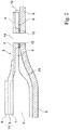
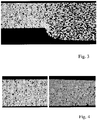
- FIG. 4 show an SEM image of a cross section of a porous carrier substrate with a pressed edge region and detailed views of the pressed edge region before (left) and after (right) a thermal surface treatment step by laser melting.
- a carrier substrate of a sieved powder of an iron-chromium alloy with a particle size less than 125 microns is prepared by conventional powder metallurgy. After sintering, the carrier substrate has a porosity of about 40% by volume.
- the edge area is subsequently compacted by uniaxial pressing, so that a residual porosity of about 7-15% by volume results in the edge area.
- a focused laser beam with a track energy of about 250 J / m is guided over the edge area to be melted and causes a superficial melting of the edge area.
- the focal point of the laser is a Melting zone of about 100 microns depth.
- the surface portion according to the invention forms, which has a melting phase.
- the cross sections are perpendicular to the surface of the plate-shaped carrier substrate.
- a embedding agent for example epoxy resin
- ground after hardening for example with finer sandpaper, respectively.
- the samples are polished with a polishing suspension and finally electrolytically polished.
- these samples are analyzed by means of SEM (scanning electron microscope) and a BSE detector (BSE: back-scattered electrons) (BSE detector or 4-quadrant ring detector). analyzed.
- BSE back-scattered electrons
- BSE detector or 4-quadrant ring detector As a scanning electron microscope while the field emission device “Ultra Pluss 55" Zeiss was used.
- the SEM image is quantitatively evaluated within a measurement area to be evaluated by means of stereological methods (software used: "Leica QWin”), whereby it is ensured that as homogeneous as possible of the part of the carrier substrate is present within the measurement area to be evaluated.
- the area fraction of the pores is determined relative to the total measuring area to be evaluated.
- This area proportion corresponds at the same time to the porosity in% by volume. Pores that lie only partially within the measurement area to be evaluated are not taken into account in the measurement process.
- the following settings were used for the SEM recording: Tilt angle: 0 °, acceleration voltage of 20 kV, working distance of approx. 10 mm and 250x magnification (device specification), resulting in a horizontal image edge of approx. 600 ⁇ m. Special emphasis was placed on a very good image sharpness.
Landscapes
- Engineering & Computer Science (AREA)
- Manufacturing & Machinery (AREA)
- Chemical & Material Sciences (AREA)
- Electrochemistry (AREA)
- Life Sciences & Earth Sciences (AREA)
- Sustainable Development (AREA)
- Sustainable Energy (AREA)
- Chemical Kinetics & Catalysis (AREA)
- General Chemical & Material Sciences (AREA)
- Mechanical Engineering (AREA)
- Composite Materials (AREA)
- Materials Engineering (AREA)
- Physics & Mathematics (AREA)
- Optics & Photonics (AREA)
- Plasma & Fusion (AREA)
- Fuel Cell (AREA)
Claims (15)
- Substrat support (1) métallique poreux, en forme de plaque fabriqué par métallurgie des poudres pour un dispositif fonctionnel électrochimique métallique présentant une zone centrale (2) et une zone de bord (3), dans lequel au niveau d'une surface de la zone centrale sur un côté du substrat support tourné vers la pile un empilement de couches avec des couches actives du point de vue électrochimique peut être agencé, caractérisé en ce qu'une section de surface (4) de la zone de bord (3) présente sur le côté du substrat support tourné vers la pile une phase de fusion du matériau de substrat support, et une zone (5) située sous la section de surface (4) présentant la phase de fusion présente au moins par section une porosité supérieure à celle de la section de surface (4) présentant la phase de fusion disposée au-dessus, dans lequel une barrière plane est formée le long de la surface du substrat support.
- Substrat support selon la revendication 1, caractérisé en ce que la zone de bord présente une densité supérieure et une porosité inférieure à celles de la zone centrale.
- Substrat support selon la revendication 1 à 2, caractérisé en ce que la section de surface présentant la phase de fusion, entourant la périphérie extérieure de la zone centrale (2), s'étend jusqu'aux arêtes extérieures de la zone de bord (3).
- Substrat support selon la revendication 1 à 3, caractérisé en ce que la section de surface (4) présentant la phase de fusion s'étend dans une direction perpendiculaire au côté du substrat support tourné vers la pile au moins 1 µm de la surface dans le substrat support.
- Substrat support selon l'une quelconque des revendications précédentes, caractérisé en ce que la section de surface (4) présentant la phase de fusion présente une porosité résiduelle d'au plus 2 %.
- Substrat support selon l'une quelconque des revendications précédentes, caractérisé en ce qu'il est réalisé d'un seul tenant.
- Substrat support selon l'une quelconque des revendications précédentes, caractérisé en ce que la zone centrale présente une porosité de 20 à 60 % et/ou la zone de bord (5) présente une porosité inférieure à 20 %.
- Substrat support selon l'une quelconque des revendications précédentes, caractérisé en ce que le substrat support se compose d'un alliage Fe-Cr.
- Substrat support selon l'une quelconque des revendications précédentes, caractérisé en ce que la section de surface présentant la phase de fusion s'étend aux alentours d'arêtes de la zone de bord sur toute l'épaisseur du substrat support jusqu'à la surface opposée.
- Substrat support selon l'une quelconque des revendications précédentes, caractérisé en ce que la zone de bord présente au moins une ouverture de passage de gaz.
- Ensemble de substrat support présentant un substrat support selon la revendication 1 à 9, caractérisé en ce que l'ensemble de substrat support présente en outre un moyen formant cadre en matériau électriquement conducteur, le moyen formant cadre est en contact électrique avec le substrat support et le moyen formant cadre présente au moins une ouverture de passage de gaz.
- Pile à combustible, présente au moins un substrat support selon la revendication 10 ou un ensemble de substrat support selon la revendication 11, dans laquelle un empilement de couches avec des couches actives du point de vue électrochimique est agencé au niveau de la surface de la zone centrale du substrat support et une couche d'électrolyte des couches actives du point de vue électrochimique est réalisée par chevauchement avec la section de surface présentant la phase de fusion.
- Procédé de fabrication d'un substrat support pour un dispositif fonctionnel électrochimique métallique, caractérisé en ce que celui-ci comprend au moins les étapes suivantes :- fabrication par métallurgie des poudres d'un substrat support en forme de plaque avec une zone centrale et une zone de bord, dans lequel au niveau d'une surface de la zone centrale sur un côté du substrat support tourné vers la pile un empilement de couches avec des couches actives du point de vue électrochimique peut être agencé- posttraitement d'au moins une partie de la zone de bord sur le côté du substrat support tourné vers la pile par fusion superficielle locale, ce par quoi une barrière plane est formée le long de la surface du substrat support.
- Procédé selon la revendication 13, caractérisé en ce qu'avant la fusion superficielle au moins une partie de la zone de bord est comprimée, de sorte qu'elle présente une porosité inférieure à celle de la zone centrale du substrat support.
- Procédé selon la revendication 13 ou 14, caractérisé en ce qu'un empilement de couches avec des couches actives du point de vue électrochimique est appliqué dans la zone centrale du substrat support.
Applications Claiming Priority (2)
| Application Number | Priority Date | Filing Date | Title |
|---|---|---|---|
| DE102013008473.3A DE102013008473A1 (de) | 2013-05-21 | 2013-05-21 | Brennstoffzelle |
| PCT/EP2014/001219 WO2014187534A1 (fr) | 2013-05-21 | 2014-05-07 | Pile à combustible |
Publications (2)
| Publication Number | Publication Date |
|---|---|
| EP3000145A1 EP3000145A1 (fr) | 2016-03-30 |
| EP3000145B1 true EP3000145B1 (fr) | 2017-11-08 |
Family
ID=50771229
Family Applications (1)
| Application Number | Title | Priority Date | Filing Date |
|---|---|---|---|
| EP14725359.5A Not-in-force EP3000145B1 (fr) | 2013-05-21 | 2014-05-07 | Pile à combustible |
Country Status (10)
| Country | Link |
|---|---|
| US (1) | US20160111732A1 (fr) |
| EP (1) | EP3000145B1 (fr) |
| JP (1) | JP6360159B2 (fr) |
| KR (1) | KR102167852B1 (fr) |
| CN (1) | CN105518918B (fr) |
| CA (1) | CA2910214A1 (fr) |
| DE (1) | DE102013008473A1 (fr) |
| DK (1) | DK3000145T3 (fr) |
| TW (1) | TWI617673B (fr) |
| WO (1) | WO2014187534A1 (fr) |
Families Citing this family (7)
| Publication number | Priority date | Publication date | Assignee | Title |
|---|---|---|---|---|
| AT14455U3 (de) | 2015-07-14 | 2017-05-15 | Plansee Se | Elektrochemisches Modul |
| JP6910170B2 (ja) * | 2017-03-22 | 2021-07-28 | 大阪瓦斯株式会社 | 金属支持型電気化学素子用の電極層付基板、電気化学素子、電気化学モジュール、電気化学装置、エネルギーシステム、固体酸化物形燃料電池、および製造方法 |
| WO2019026138A1 (fr) * | 2017-07-31 | 2019-02-07 | 日産自動車株式会社 | Cellule de batterie à combustible |
| EP3830316A1 (fr) * | 2018-07-27 | 2021-06-09 | Hoeller Electrolyzer GmbH | Procédé de fabrication d'une couche de transport poreuse pour une cellule électrochimique |
| DE102019208908A1 (de) * | 2019-06-19 | 2020-12-24 | Robert Bosch Gmbh | Verfahren zur Herstellung einer Brennstoffzelle |
| DE102020203398A1 (de) | 2020-03-17 | 2021-09-23 | Robert Bosch Gesellschaft mit beschränkter Haftung | Verfahren zur additiven Herstellung eines Metallträgers einer Brennstoffzelle |
| CN113067005A (zh) * | 2021-03-19 | 2021-07-02 | 东睦新材料集团股份有限公司 | 一种用于燃料电池的金属支撑板的制备方法 |
Family Cites Families (17)
| Publication number | Priority date | Publication date | Assignee | Title |
|---|---|---|---|---|
| JPH10106597A (ja) * | 1996-09-25 | 1998-04-24 | Fuji Electric Co Ltd | 固体電解質型燃料電池 |
| DE59803737D1 (de) * | 1997-02-11 | 2002-05-16 | Fucellco Inc | Brennstoffzellenstapel mit festen elektrolyten und deren anordnung |
| GB2368450B (en) | 2000-10-25 | 2004-05-19 | Imperial College | Fuel cells |
| US6489584B1 (en) * | 2001-05-08 | 2002-12-03 | General Electric Company | Room-temperature surface weld repair of nickel-base superalloys having a nil-ductility range |
| DE10135333A1 (de) | 2001-07-19 | 2003-02-06 | Elringklinger Ag | Brennstoffzelleneinheit |
| DE10135336C1 (de) * | 2001-07-19 | 2002-11-07 | Elringklinger Ag | Brennstoffzelleneinheit für einen Brennstoffzellenblockverbund |
| DE10210293B4 (de) * | 2002-03-08 | 2006-11-23 | Elringklinger Ag | Brennstoffzellenblockverbund und Verfahren zum Herstellen eines Brennstoffzellenblockverbunds |
| AT8975U1 (de) | 2006-02-27 | 2007-03-15 | Plansee Se | Poröser körper |
| JP5172207B2 (ja) * | 2006-10-24 | 2013-03-27 | 日本碍子株式会社 | 固体酸化物型燃料電池の単セル用の薄板体 |
| US8907248B2 (en) * | 2007-05-03 | 2014-12-09 | Illinois Tool Works Inc. | Aluminum deoxidizing welding wire |
| DE102007024225A1 (de) | 2007-05-11 | 2008-11-13 | Deutsches Zentrum für Luft- und Raumfahrt e.V. | Trägervorrichtung für eine elektrochemische Funktionseinrichtung, Brennstoffzellenmodul und Verfahren zur Herstellung einer Trägervorrichtung |
| DE102007034967A1 (de) * | 2007-07-26 | 2009-01-29 | Plansee Se | Brennstoffzelle und Verfahren zu deren Herstellung |
| ES2382406T3 (es) * | 2007-10-05 | 2012-06-08 | Topsoe Fuel Cell A/S | Junta de sellado para un soporte metálico poroso en una pila de combustible |
| JP5335068B2 (ja) * | 2008-04-18 | 2013-11-06 | ザ、リージェンツ、オブ、ザ、ユニバーシティ、オブ、カリフォルニア | 電気化学装置構成及びその製法 |
| DE102008049606A1 (de) * | 2008-09-30 | 2010-04-01 | Siemens Aktiengesellschaft | Verfahren zur Verringerung der Chromdiffusion aus Chrom enthaltenden, gesinterten porösen Metallsubstraten zwecks Verwendung in einer Hochtemperatur-Brennstoffzelle bzw. Brennstoffzellenanlage |
| FR2938270B1 (fr) * | 2008-11-12 | 2013-10-18 | Commissariat Energie Atomique | Substrat en metal ou alliage metallique poreux, son procede de preparation, et cellules d'eht ou de sofc a metal support comprenant ce substrat |
| AT14455U3 (de) * | 2015-07-14 | 2017-05-15 | Plansee Se | Elektrochemisches Modul |
-
2013
- 2013-05-21 DE DE102013008473.3A patent/DE102013008473A1/de not_active Withdrawn
-
2014
- 2014-04-23 TW TW103114612A patent/TWI617673B/zh not_active IP Right Cessation
- 2014-05-07 CN CN201480029476.6A patent/CN105518918B/zh active Active
- 2014-05-07 EP EP14725359.5A patent/EP3000145B1/fr not_active Not-in-force
- 2014-05-07 KR KR1020157032748A patent/KR102167852B1/ko active IP Right Grant
- 2014-05-07 WO PCT/EP2014/001219 patent/WO2014187534A1/fr active Application Filing
- 2014-05-07 US US14/893,163 patent/US20160111732A1/en not_active Abandoned
- 2014-05-07 CA CA2910214A patent/CA2910214A1/fr not_active Abandoned
- 2014-05-07 DK DK14725359.5T patent/DK3000145T3/en active
- 2014-05-07 JP JP2016514292A patent/JP6360159B2/ja not_active Expired - Fee Related
Non-Patent Citations (1)
| Title |
|---|
| None * |
Also Published As
| Publication number | Publication date |
|---|---|
| CA2910214A1 (fr) | 2014-11-27 |
| JP6360159B2 (ja) | 2018-07-18 |
| DE102013008473A1 (de) | 2014-11-27 |
| DK3000145T3 (en) | 2018-02-12 |
| TWI617673B (zh) | 2018-03-11 |
| US20160111732A1 (en) | 2016-04-21 |
| JP2016519413A (ja) | 2016-06-30 |
| WO2014187534A1 (fr) | 2014-11-27 |
| EP3000145A1 (fr) | 2016-03-30 |
| KR102167852B1 (ko) | 2020-10-21 |
| CN105518918A (zh) | 2016-04-20 |
| CN105518918B (zh) | 2018-08-10 |
| KR20160010454A (ko) | 2016-01-27 |
| TW201446972A (zh) | 2014-12-16 |
Similar Documents
| Publication | Publication Date | Title |
|---|---|---|
| EP3000145B1 (fr) | Pile à combustible | |
| EP3323168B1 (fr) | Module électrochimique | |
| EP2174371B1 (fr) | Procédé de fabrication d'une pile à combustible | |
| EP2230707A1 (fr) | Inter-connecteur d'une cellule de combustible à haute température dotée d'un électrolyte solide | |
| EP2335312A1 (fr) | Procédé de fabrication d'un interconnecteur pour piles à combustible à haute température, pile à combustible à haute température correspondante et système de piles à combustible constitué de piles à combustible de ce type | |
| DE102014118358A1 (de) | Einzelzelle mit angebrachtem Separator und Brennstoffzellenstapel, undVerfahren zur Herstellung einer Einzelzelle mit angebrachtem Separator | |
| DE102007024227A1 (de) | Hochtemperatur-Brennstoffzellenmodul und Verfahren zur Herstellung eines Hochtemperatur-Brennstoffzellenmoduls | |
| WO2018165682A1 (fr) | Pièce moulée poreuse destinée à un module électrochimique | |
| EP3014685B1 (fr) | Élément à haute température comprenant une couche poreuse de conduits de guidage de gaz | |
| EP2156499B1 (fr) | Procédé de réalisation d'une couche d'électrolyte solide étanche aux gaz et couche d'électrolyte solide correspondante | |
| DE102008006038B4 (de) | Verfahren zur Herstellung einer Bipolarplatte für eine Brennstoffzelleneinheit und Bipolarplatte | |
| WO2021198137A1 (fr) | Procédé de fabrication d'une structure conductrice de gaz et/ou d'électrons et pile à combustible/cellule d'électrolyse | |
| DE102008049712A1 (de) | Planare Hochtemperatur-Brennstoffzelle | |
| EP2342777A1 (fr) | Pile à combustible tubulaire à haute température, procédé pour sa fabrication et système de piles à combustible comprenant une telle pile à combustible | |
| WO2005024990A1 (fr) | Pile a combustible a oxyde solide et son procede de production | |
| WO2018165683A1 (fr) | Élément de guidage de gaz poreux, fonctionnalisé et destiné à un module électrochimique | |
| WO2018191765A1 (fr) | Unité électrode-électrolyte | |
| WO2022048796A1 (fr) | Procédé de fabrication de papier vert destiné à la fabrication d'une couche de diffusion gazeuse pour une pile à combustible | |
| DE102009037207A1 (de) | Verfahren zum Verbinden einer Bipolarplatte mit einer Elektrode und mit einem weiteren Bauteil eines Brennstoffzellenstacks und eine solche Bipolarplatte umfassende Baugruppe eines Brennstoffzellenstacks | |
| EP4154333A1 (fr) | Procédé de fabrication d'une cellule électrochimique |
Legal Events
| Date | Code | Title | Description |
|---|---|---|---|
| PUAI | Public reference made under article 153(3) epc to a published international application that has entered the european phase |
Free format text: ORIGINAL CODE: 0009012 |
|
| 17P | Request for examination filed |
Effective date: 20151028 |
|
| AK | Designated contracting states |
Kind code of ref document: A1 Designated state(s): AL AT BE BG CH CY CZ DE DK EE ES FI FR GB GR HR HU IE IS IT LI LT LU LV MC MK MT NL NO PL PT RO RS SE SI SK SM TR |
|
| AX | Request for extension of the european patent |
Extension state: BA ME |
|
| RIN1 | Information on inventor provided before grant (corrected) |
Inventor name: ZOBL, GEBHARD Inventor name: RUETTINGER, MATTHIAS Inventor name: KOEGL, MARKUS Inventor name: HAYDN, MARKUS Inventor name: FRANCO, THOMAS |
|
| DAX | Request for extension of the european patent (deleted) | ||
| REG | Reference to a national code |
Ref country code: DE Ref legal event code: R079 Ref document number: 502014006145 Country of ref document: DE Free format text: PREVIOUS MAIN CLASS: H01M0008020000 Ipc: H01M0008023000 |
|
| GRAP | Despatch of communication of intention to grant a patent |
Free format text: ORIGINAL CODE: EPIDOSNIGR1 |
|
| RIC1 | Information provided on ipc code assigned before grant |
Ipc: B23K 26/00 20140101ALI20170517BHEP Ipc: B23K 26/354 20140101ALI20170517BHEP Ipc: H01M 8/023 20160101AFI20170517BHEP Ipc: H01M 8/0245 20160101ALI20170517BHEP Ipc: B22F 3/02 20060101ALI20170517BHEP Ipc: H01M 8/0273 20160101ALI20170517BHEP Ipc: H01M 8/124 20160101ALN20170517BHEP Ipc: B22F 7/00 20060101ALI20170517BHEP Ipc: H01M 8/0232 20160101ALI20170517BHEP Ipc: B22F 3/11 20060101ALI20170517BHEP |
|
| INTG | Intention to grant announced |
Effective date: 20170621 |
|
| GRAS | Grant fee paid |
Free format text: ORIGINAL CODE: EPIDOSNIGR3 |
|
| GRAA | (expected) grant |
Free format text: ORIGINAL CODE: 0009210 |
|
| AK | Designated contracting states |
Kind code of ref document: B1 Designated state(s): AL AT BE BG CH CY CZ DE DK EE ES FI FR GB GR HR HU IE IS IT LI LT LU LV MC MK MT NL NO PL PT RO RS SE SI SK SM TR |
|
| REG | Reference to a national code |
Ref country code: GB Ref legal event code: FG4D Free format text: NOT ENGLISH |
|
| REG | Reference to a national code |
Ref country code: CH Ref legal event code: EP Ref country code: AT Ref legal event code: REF Ref document number: 944967 Country of ref document: AT Kind code of ref document: T Effective date: 20171115 |
|
| REG | Reference to a national code |
Ref country code: IE Ref legal event code: FG4D Free format text: LANGUAGE OF EP DOCUMENT: GERMAN |
|
| REG | Reference to a national code |
Ref country code: DE Ref legal event code: R096 Ref document number: 502014006145 Country of ref document: DE |
|
| REG | Reference to a national code |
Ref country code: DK Ref legal event code: T3 Effective date: 20180207 |
|
| REG | Reference to a national code |
Ref country code: SE Ref legal event code: TRGR |
|
| REG | Reference to a national code |
Ref country code: NL Ref legal event code: MP Effective date: 20171108 |
|
| REG | Reference to a national code |
Ref country code: LT Ref legal event code: MG4D |
|
| PG25 | Lapsed in a contracting state [announced via postgrant information from national office to epo] |
Ref country code: LT Free format text: LAPSE BECAUSE OF FAILURE TO SUBMIT A TRANSLATION OF THE DESCRIPTION OR TO PAY THE FEE WITHIN THE PRESCRIBED TIME-LIMIT Effective date: 20171108 Ref country code: ES Free format text: LAPSE BECAUSE OF FAILURE TO SUBMIT A TRANSLATION OF THE DESCRIPTION OR TO PAY THE FEE WITHIN THE PRESCRIBED TIME-LIMIT Effective date: 20171108 Ref country code: NL Free format text: LAPSE BECAUSE OF FAILURE TO SUBMIT A TRANSLATION OF THE DESCRIPTION OR TO PAY THE FEE WITHIN THE PRESCRIBED TIME-LIMIT Effective date: 20171108 Ref country code: NO Free format text: LAPSE BECAUSE OF FAILURE TO SUBMIT A TRANSLATION OF THE DESCRIPTION OR TO PAY THE FEE WITHIN THE PRESCRIBED TIME-LIMIT Effective date: 20180208 |
|
| REG | Reference to a national code |
Ref country code: FR Ref legal event code: PLFP Year of fee payment: 5 |
|
| PG25 | Lapsed in a contracting state [announced via postgrant information from national office to epo] |
Ref country code: IS Free format text: LAPSE BECAUSE OF FAILURE TO SUBMIT A TRANSLATION OF THE DESCRIPTION OR TO PAY THE FEE WITHIN THE PRESCRIBED TIME-LIMIT Effective date: 20180308 Ref country code: GR Free format text: LAPSE BECAUSE OF FAILURE TO SUBMIT A TRANSLATION OF THE DESCRIPTION OR TO PAY THE FEE WITHIN THE PRESCRIBED TIME-LIMIT Effective date: 20180209 Ref country code: LV Free format text: LAPSE BECAUSE OF FAILURE TO SUBMIT A TRANSLATION OF THE DESCRIPTION OR TO PAY THE FEE WITHIN THE PRESCRIBED TIME-LIMIT Effective date: 20171108 Ref country code: RS Free format text: LAPSE BECAUSE OF FAILURE TO SUBMIT A TRANSLATION OF THE DESCRIPTION OR TO PAY THE FEE WITHIN THE PRESCRIBED TIME-LIMIT Effective date: 20171108 Ref country code: BG Free format text: LAPSE BECAUSE OF FAILURE TO SUBMIT A TRANSLATION OF THE DESCRIPTION OR TO PAY THE FEE WITHIN THE PRESCRIBED TIME-LIMIT Effective date: 20180208 Ref country code: HR Free format text: LAPSE BECAUSE OF FAILURE TO SUBMIT A TRANSLATION OF THE DESCRIPTION OR TO PAY THE FEE WITHIN THE PRESCRIBED TIME-LIMIT Effective date: 20171108 |
|
| PG25 | Lapsed in a contracting state [announced via postgrant information from national office to epo] |
Ref country code: SK Free format text: LAPSE BECAUSE OF FAILURE TO SUBMIT A TRANSLATION OF THE DESCRIPTION OR TO PAY THE FEE WITHIN THE PRESCRIBED TIME-LIMIT Effective date: 20171108 Ref country code: CZ Free format text: LAPSE BECAUSE OF FAILURE TO SUBMIT A TRANSLATION OF THE DESCRIPTION OR TO PAY THE FEE WITHIN THE PRESCRIBED TIME-LIMIT Effective date: 20171108 Ref country code: EE Free format text: LAPSE BECAUSE OF FAILURE TO SUBMIT A TRANSLATION OF THE DESCRIPTION OR TO PAY THE FEE WITHIN THE PRESCRIBED TIME-LIMIT Effective date: 20171108 Ref country code: CY Free format text: LAPSE BECAUSE OF FAILURE TO SUBMIT A TRANSLATION OF THE DESCRIPTION OR TO PAY THE FEE WITHIN THE PRESCRIBED TIME-LIMIT Effective date: 20171108 |
|
| REG | Reference to a national code |
Ref country code: DE Ref legal event code: R097 Ref document number: 502014006145 Country of ref document: DE |
|
| PG25 | Lapsed in a contracting state [announced via postgrant information from national office to epo] |
Ref country code: PL Free format text: LAPSE BECAUSE OF FAILURE TO SUBMIT A TRANSLATION OF THE DESCRIPTION OR TO PAY THE FEE WITHIN THE PRESCRIBED TIME-LIMIT Effective date: 20171108 Ref country code: SM Free format text: LAPSE BECAUSE OF FAILURE TO SUBMIT A TRANSLATION OF THE DESCRIPTION OR TO PAY THE FEE WITHIN THE PRESCRIBED TIME-LIMIT Effective date: 20171108 Ref country code: RO Free format text: LAPSE BECAUSE OF FAILURE TO SUBMIT A TRANSLATION OF THE DESCRIPTION OR TO PAY THE FEE WITHIN THE PRESCRIBED TIME-LIMIT Effective date: 20171108 |
|
| PLBE | No opposition filed within time limit |
Free format text: ORIGINAL CODE: 0009261 |
|
| STAA | Information on the status of an ep patent application or granted ep patent |
Free format text: STATUS: NO OPPOSITION FILED WITHIN TIME LIMIT |
|
| PG25 | Lapsed in a contracting state [announced via postgrant information from national office to epo] |
Ref country code: MT Free format text: LAPSE BECAUSE OF FAILURE TO SUBMIT A TRANSLATION OF THE DESCRIPTION OR TO PAY THE FEE WITHIN THE PRESCRIBED TIME-LIMIT Effective date: 20171108 |
|
| 26N | No opposition filed |
Effective date: 20180809 |
|
| PG25 | Lapsed in a contracting state [announced via postgrant information from national office to epo] |
Ref country code: SI Free format text: LAPSE BECAUSE OF FAILURE TO SUBMIT A TRANSLATION OF THE DESCRIPTION OR TO PAY THE FEE WITHIN THE PRESCRIBED TIME-LIMIT Effective date: 20171108 |
|
| REG | Reference to a national code |
Ref country code: BE Ref legal event code: MM Effective date: 20180531 |
|
| PG25 | Lapsed in a contracting state [announced via postgrant information from national office to epo] |
Ref country code: MC Free format text: LAPSE BECAUSE OF FAILURE TO SUBMIT A TRANSLATION OF THE DESCRIPTION OR TO PAY THE FEE WITHIN THE PRESCRIBED TIME-LIMIT Effective date: 20171108 |
|
| REG | Reference to a national code |
Ref country code: IE Ref legal event code: MM4A |
|
| PG25 | Lapsed in a contracting state [announced via postgrant information from national office to epo] |
Ref country code: LU Free format text: LAPSE BECAUSE OF NON-PAYMENT OF DUE FEES Effective date: 20180507 |
|
| PG25 | Lapsed in a contracting state [announced via postgrant information from national office to epo] |
Ref country code: IE Free format text: LAPSE BECAUSE OF NON-PAYMENT OF DUE FEES Effective date: 20180507 |
|
| PG25 | Lapsed in a contracting state [announced via postgrant information from national office to epo] |
Ref country code: BE Free format text: LAPSE BECAUSE OF NON-PAYMENT OF DUE FEES Effective date: 20180531 |
|
| PG25 | Lapsed in a contracting state [announced via postgrant information from national office to epo] |
Ref country code: TR Free format text: LAPSE BECAUSE OF FAILURE TO SUBMIT A TRANSLATION OF THE DESCRIPTION OR TO PAY THE FEE WITHIN THE PRESCRIBED TIME-LIMIT Effective date: 20171108 |
|
| PG25 | Lapsed in a contracting state [announced via postgrant information from national office to epo] |
Ref country code: PT Free format text: LAPSE BECAUSE OF FAILURE TO SUBMIT A TRANSLATION OF THE DESCRIPTION OR TO PAY THE FEE WITHIN THE PRESCRIBED TIME-LIMIT Effective date: 20171108 |
|
| PG25 | Lapsed in a contracting state [announced via postgrant information from national office to epo] |
Ref country code: HU Free format text: LAPSE BECAUSE OF FAILURE TO SUBMIT A TRANSLATION OF THE DESCRIPTION OR TO PAY THE FEE WITHIN THE PRESCRIBED TIME-LIMIT; INVALID AB INITIO Effective date: 20140507 Ref country code: MK Free format text: LAPSE BECAUSE OF NON-PAYMENT OF DUE FEES Effective date: 20171108 |
|
| PG25 | Lapsed in a contracting state [announced via postgrant information from national office to epo] |
Ref country code: AL Free format text: LAPSE BECAUSE OF FAILURE TO SUBMIT A TRANSLATION OF THE DESCRIPTION OR TO PAY THE FEE WITHIN THE PRESCRIBED TIME-LIMIT Effective date: 20171108 |
|
| PGFP | Annual fee paid to national office [announced via postgrant information from national office to epo] |
Ref country code: DK Payment date: 20200527 Year of fee payment: 7 Ref country code: FI Payment date: 20200522 Year of fee payment: 7 Ref country code: CH Payment date: 20200520 Year of fee payment: 7 Ref country code: FR Payment date: 20200522 Year of fee payment: 7 |
|
| PGFP | Annual fee paid to national office [announced via postgrant information from national office to epo] |
Ref country code: SE Payment date: 20200527 Year of fee payment: 7 Ref country code: IT Payment date: 20200528 Year of fee payment: 7 Ref country code: GB Payment date: 20200527 Year of fee payment: 7 |
|
| PGFP | Annual fee paid to national office [announced via postgrant information from national office to epo] |
Ref country code: AT Payment date: 20200522 Year of fee payment: 7 |
|
| REG | Reference to a national code |
Ref country code: FI Ref legal event code: MAE |
|
| REG | Reference to a national code |
Ref country code: DK Ref legal event code: EBP Effective date: 20210531 |
|
| REG | Reference to a national code |
Ref country code: SE Ref legal event code: EUG |
|
| REG | Reference to a national code |
Ref country code: CH Ref legal event code: PL |
|
| REG | Reference to a national code |
Ref country code: AT Ref legal event code: MM01 Ref document number: 944967 Country of ref document: AT Kind code of ref document: T Effective date: 20210507 |
|
| GBPC | Gb: european patent ceased through non-payment of renewal fee |
Effective date: 20210507 |
|
| PG25 | Lapsed in a contracting state [announced via postgrant information from national office to epo] |
Ref country code: LI Free format text: LAPSE BECAUSE OF NON-PAYMENT OF DUE FEES Effective date: 20210531 Ref country code: CH Free format text: LAPSE BECAUSE OF NON-PAYMENT OF DUE FEES Effective date: 20210531 Ref country code: AT Free format text: LAPSE BECAUSE OF NON-PAYMENT OF DUE FEES Effective date: 20210507 Ref country code: FI Free format text: LAPSE BECAUSE OF NON-PAYMENT OF DUE FEES Effective date: 20210507 Ref country code: SE Free format text: LAPSE BECAUSE OF NON-PAYMENT OF DUE FEES Effective date: 20210508 |
|
| PG25 | Lapsed in a contracting state [announced via postgrant information from national office to epo] |
Ref country code: GB Free format text: LAPSE BECAUSE OF NON-PAYMENT OF DUE FEES Effective date: 20210507 Ref country code: DK Free format text: LAPSE BECAUSE OF NON-PAYMENT OF DUE FEES Effective date: 20210531 |
|
| PG25 | Lapsed in a contracting state [announced via postgrant information from national office to epo] |
Ref country code: FR Free format text: LAPSE BECAUSE OF NON-PAYMENT OF DUE FEES Effective date: 20210531 |
|
| PGFP | Annual fee paid to national office [announced via postgrant information from national office to epo] |
Ref country code: DE Payment date: 20220519 Year of fee payment: 9 |
|
| PG25 | Lapsed in a contracting state [announced via postgrant information from national office to epo] |
Ref country code: IT Free format text: LAPSE BECAUSE OF NON-PAYMENT OF DUE FEES Effective date: 20200507 |
|
| REG | Reference to a national code |
Ref country code: DE Ref legal event code: R119 Ref document number: 502014006145 Country of ref document: DE |
|
| PG25 | Lapsed in a contracting state [announced via postgrant information from national office to epo] |
Ref country code: DE Free format text: LAPSE BECAUSE OF NON-PAYMENT OF DUE FEES Effective date: 20231201 |