EP3000145B1 - Fuel cell - Google Patents
Fuel cell Download PDFInfo
- Publication number
- EP3000145B1 EP3000145B1 EP14725359.5A EP14725359A EP3000145B1 EP 3000145 B1 EP3000145 B1 EP 3000145B1 EP 14725359 A EP14725359 A EP 14725359A EP 3000145 B1 EP3000145 B1 EP 3000145B1
- Authority
- EP
- European Patent Office
- Prior art keywords
- carrier substrate
- region
- central region
- gas
- melt phase
- Prior art date
- Legal status (The legal status is an assumption and is not a legal conclusion. Google has not performed a legal analysis and makes no representation as to the accuracy of the status listed.)
- Not-in-force
Links
- 239000000446 fuel Substances 0.000 title claims description 23
- 239000000758 substrate Substances 0.000 claims description 122
- 238000000034 method Methods 0.000 claims description 30
- 239000000155 melt Substances 0.000 claims description 24
- 238000002844 melting Methods 0.000 claims description 21
- 230000008018 melting Effects 0.000 claims description 21
- 239000003792 electrolyte Substances 0.000 claims description 19
- 230000004888 barrier function Effects 0.000 claims description 9
- 239000000463 material Substances 0.000 claims description 9
- 229910045601 alloy Inorganic materials 0.000 claims description 4
- 239000000956 alloy Substances 0.000 claims description 4
- UPHIPHFJVNKLMR-UHFFFAOYSA-N chromium iron Chemical compound [Cr].[Fe] UPHIPHFJVNKLMR-UHFFFAOYSA-N 0.000 claims description 4
- 238000004519 manufacturing process Methods 0.000 claims description 3
- 238000004663 powder metallurgy Methods 0.000 claims description 3
- 229910017060 Fe Cr Inorganic materials 0.000 claims description 2
- 229910002544 Fe-Cr Inorganic materials 0.000 claims description 2
- 239000004020 conductor Substances 0.000 claims description 2
- 239000007789 gas Substances 0.000 description 35
- 239000010410 layer Substances 0.000 description 30
- 210000004027 cell Anatomy 0.000 description 24
- 230000008569 process Effects 0.000 description 20
- 229910052751 metal Inorganic materials 0.000 description 11
- 239000002184 metal Substances 0.000 description 11
- 239000002737 fuel gas Substances 0.000 description 10
- 239000000843 powder Substances 0.000 description 9
- 239000000919 ceramic Substances 0.000 description 7
- 239000002346 layers by function Substances 0.000 description 6
- 238000000926 separation method Methods 0.000 description 6
- 238000005259 measurement Methods 0.000 description 5
- 238000004381 surface treatment Methods 0.000 description 5
- 238000011161 development Methods 0.000 description 4
- VNWKTOKETHGBQD-UHFFFAOYSA-N methane Chemical compound C VNWKTOKETHGBQD-UHFFFAOYSA-N 0.000 description 4
- 239000011148 porous material Substances 0.000 description 4
- 238000007789 sealing Methods 0.000 description 4
- 238000005476 soldering Methods 0.000 description 4
- 239000010409 thin film Substances 0.000 description 4
- 238000003466 welding Methods 0.000 description 4
- 238000013459 approach Methods 0.000 description 3
- 230000008901 benefit Effects 0.000 description 3
- 238000005056 compaction Methods 0.000 description 3
- 238000007906 compression Methods 0.000 description 3
- 150000002500 ions Chemical class 0.000 description 3
- 238000010309 melting process Methods 0.000 description 3
- 239000001301 oxygen Substances 0.000 description 3
- 229910052760 oxygen Inorganic materials 0.000 description 3
- 239000002245 particle Substances 0.000 description 3
- 229910052706 scandium Inorganic materials 0.000 description 3
- 238000005245 sintering Methods 0.000 description 3
- 239000007784 solid electrolyte Substances 0.000 description 3
- 229910000599 Cr alloy Inorganic materials 0.000 description 2
- 230000015572 biosynthetic process Effects 0.000 description 2
- 238000005422 blasting Methods 0.000 description 2
- 238000001311 chemical methods and process Methods 0.000 description 2
- 239000011651 chromium Substances 0.000 description 2
- 239000000788 chromium alloy Substances 0.000 description 2
- 238000000576 coating method Methods 0.000 description 2
- 239000002131 composite material Substances 0.000 description 2
- 230000006835 compression Effects 0.000 description 2
- 238000001816 cooling Methods 0.000 description 2
- 238000005520 cutting process Methods 0.000 description 2
- 238000009792 diffusion process Methods 0.000 description 2
- 238000000227 grinding Methods 0.000 description 2
- 230000010354 integration Effects 0.000 description 2
- 229910052748 manganese Inorganic materials 0.000 description 2
- 239000007800 oxidant agent Substances 0.000 description 2
- -1 oxygen ions Chemical class 0.000 description 2
- 238000005240 physical vapour deposition Methods 0.000 description 2
- 238000003825 pressing Methods 0.000 description 2
- 238000012545 processing Methods 0.000 description 2
- 229910052761 rare earth metal Inorganic materials 0.000 description 2
- 150000002910 rare earth metals Chemical class 0.000 description 2
- 238000001878 scanning electron micrograph Methods 0.000 description 2
- 230000003746 surface roughness Effects 0.000 description 2
- 229910052719 titanium Inorganic materials 0.000 description 2
- 238000003826 uniaxial pressing Methods 0.000 description 2
- 229910052727 yttrium Inorganic materials 0.000 description 2
- UFHFLCQGNIYNRP-UHFFFAOYSA-N Hydrogen Chemical compound [H][H] UFHFLCQGNIYNRP-UHFFFAOYSA-N 0.000 description 1
- 230000001133 acceleration Effects 0.000 description 1
- 229910052782 aluminium Inorganic materials 0.000 description 1
- QVGXLLKOCUKJST-UHFFFAOYSA-N atomic oxygen Chemical compound [O] QVGXLLKOCUKJST-UHFFFAOYSA-N 0.000 description 1
- 210000003850 cellular structure Anatomy 0.000 description 1
- 229910010293 ceramic material Inorganic materials 0.000 description 1
- QAISYPNSOYCTPY-UHFFFAOYSA-N cerium(3+) gadolinium(3+) oxygen(2-) Chemical compound [O--].[O--].[O--].[Ce+3].[Gd+3] QAISYPNSOYCTPY-UHFFFAOYSA-N 0.000 description 1
- 230000008859 change Effects 0.000 description 1
- 239000003795 chemical substances by application Substances 0.000 description 1
- 229910052804 chromium Inorganic materials 0.000 description 1
- 239000011248 coating agent Substances 0.000 description 1
- 229910003460 diamond Inorganic materials 0.000 description 1
- 239000010432 diamond Substances 0.000 description 1
- 230000000694 effects Effects 0.000 description 1
- 238000004049 embossing Methods 0.000 description 1
- 238000005516 engineering process Methods 0.000 description 1
- 239000003822 epoxy resin Substances 0.000 description 1
- 238000011049 filling Methods 0.000 description 1
- 238000010285 flame spraying Methods 0.000 description 1
- 239000012530 fluid Substances 0.000 description 1
- 229910052735 hafnium Inorganic materials 0.000 description 1
- 238000010438 heat treatment Methods 0.000 description 1
- 229930195733 hydrocarbon Natural products 0.000 description 1
- 150000002430 hydrocarbons Chemical class 0.000 description 1
- 239000001257 hydrogen Substances 0.000 description 1
- 229910052739 hydrogen Inorganic materials 0.000 description 1
- 239000012535 impurity Substances 0.000 description 1
- 238000010884 ion-beam technique Methods 0.000 description 1
- 238000005304 joining Methods 0.000 description 1
- 230000007774 longterm Effects 0.000 description 1
- 238000012423 maintenance Methods 0.000 description 1
- 239000012528 membrane Substances 0.000 description 1
- 229910044991 metal oxide Inorganic materials 0.000 description 1
- 150000004706 metal oxides Chemical class 0.000 description 1
- 150000002739 metals Chemical class 0.000 description 1
- 239000000203 mixture Substances 0.000 description 1
- 239000003345 natural gas Substances 0.000 description 1
- 229910052759 nickel Inorganic materials 0.000 description 1
- 229910052758 niobium Inorganic materials 0.000 description 1
- 230000001590 oxidative effect Effects 0.000 description 1
- 230000002093 peripheral effect Effects 0.000 description 1
- 238000007750 plasma spraying Methods 0.000 description 1
- 238000005498 polishing Methods 0.000 description 1
- 229920000647 polyepoxide Polymers 0.000 description 1
- SIXSYDAISGFNSX-UHFFFAOYSA-N scandium atom Chemical compound [Sc] SIXSYDAISGFNSX-UHFFFAOYSA-N 0.000 description 1
- 238000007650 screen-printing Methods 0.000 description 1
- 239000007787 solid Substances 0.000 description 1
- 238000007711 solidification Methods 0.000 description 1
- 230000008023 solidification Effects 0.000 description 1
- 229910002076 stabilized zirconia Inorganic materials 0.000 description 1
- 239000007858 starting material Substances 0.000 description 1
- 239000000126 substance Substances 0.000 description 1
- 239000000725 suspension Substances 0.000 description 1
- 229910052715 tantalum Inorganic materials 0.000 description 1
- 230000007704 transition Effects 0.000 description 1
- 229910052721 tungsten Inorganic materials 0.000 description 1
- XLYOFNOQVPJJNP-UHFFFAOYSA-N water Substances O XLYOFNOQVPJJNP-UHFFFAOYSA-N 0.000 description 1
- RUDFQVOCFDJEEF-UHFFFAOYSA-N yttrium(III) oxide Inorganic materials [O-2].[O-2].[O-2].[Y+3].[Y+3] RUDFQVOCFDJEEF-UHFFFAOYSA-N 0.000 description 1
- 229910052726 zirconium Inorganic materials 0.000 description 1
Images

Classifications
-
- H—ELECTRICITY
- H01—ELECTRIC ELEMENTS
- H01M—PROCESSES OR MEANS, e.g. BATTERIES, FOR THE DIRECT CONVERSION OF CHEMICAL ENERGY INTO ELECTRICAL ENERGY
- H01M8/00—Fuel cells; Manufacture thereof
- H01M8/02—Details
- H01M8/0202—Collectors; Separators, e.g. bipolar separators; Interconnectors
- H01M8/023—Porous and characterised by the material
- H01M8/0232—Metals or alloys
-
- B—PERFORMING OPERATIONS; TRANSPORTING
- B22—CASTING; POWDER METALLURGY
- B22F—WORKING METALLIC POWDER; MANUFACTURE OF ARTICLES FROM METALLIC POWDER; MAKING METALLIC POWDER; APPARATUS OR DEVICES SPECIALLY ADAPTED FOR METALLIC POWDER
- B22F3/00—Manufacture of workpieces or articles from metallic powder characterised by the manner of compacting or sintering; Apparatus specially adapted therefor ; Presses and furnaces
- B22F3/02—Compacting only
-
- B—PERFORMING OPERATIONS; TRANSPORTING
- B22—CASTING; POWDER METALLURGY
- B22F—WORKING METALLIC POWDER; MANUFACTURE OF ARTICLES FROM METALLIC POWDER; MAKING METALLIC POWDER; APPARATUS OR DEVICES SPECIALLY ADAPTED FOR METALLIC POWDER
- B22F3/00—Manufacture of workpieces or articles from metallic powder characterised by the manner of compacting or sintering; Apparatus specially adapted therefor ; Presses and furnaces
- B22F3/10—Sintering only
- B22F3/11—Making porous workpieces or articles
-
- B—PERFORMING OPERATIONS; TRANSPORTING
- B22—CASTING; POWDER METALLURGY
- B22F—WORKING METALLIC POWDER; MANUFACTURE OF ARTICLES FROM METALLIC POWDER; MAKING METALLIC POWDER; APPARATUS OR DEVICES SPECIALLY ADAPTED FOR METALLIC POWDER
- B22F7/00—Manufacture of composite layers, workpieces, or articles, comprising metallic powder, by sintering the powder, with or without compacting wherein at least one part is obtained by sintering or compression
- B22F7/002—Manufacture of composite layers, workpieces, or articles, comprising metallic powder, by sintering the powder, with or without compacting wherein at least one part is obtained by sintering or compression of porous nature
-
- B—PERFORMING OPERATIONS; TRANSPORTING
- B23—MACHINE TOOLS; METAL-WORKING NOT OTHERWISE PROVIDED FOR
- B23K—SOLDERING OR UNSOLDERING; WELDING; CLADDING OR PLATING BY SOLDERING OR WELDING; CUTTING BY APPLYING HEAT LOCALLY, e.g. FLAME CUTTING; WORKING BY LASER BEAM
- B23K26/00—Working by laser beam, e.g. welding, cutting or boring
- B23K26/352—Working by laser beam, e.g. welding, cutting or boring for surface treatment
- B23K26/354—Working by laser beam, e.g. welding, cutting or boring for surface treatment by melting
-
- H—ELECTRICITY
- H01—ELECTRIC ELEMENTS
- H01M—PROCESSES OR MEANS, e.g. BATTERIES, FOR THE DIRECT CONVERSION OF CHEMICAL ENERGY INTO ELECTRICAL ENERGY
- H01M8/00—Fuel cells; Manufacture thereof
- H01M8/02—Details
- H01M8/0202—Collectors; Separators, e.g. bipolar separators; Interconnectors
- H01M8/023—Porous and characterised by the material
- H01M8/0241—Composites
- H01M8/0245—Composites in the form of layered or coated products
-
- H—ELECTRICITY
- H01—ELECTRIC ELEMENTS
- H01M—PROCESSES OR MEANS, e.g. BATTERIES, FOR THE DIRECT CONVERSION OF CHEMICAL ENERGY INTO ELECTRICAL ENERGY
- H01M8/00—Fuel cells; Manufacture thereof
- H01M8/02—Details
- H01M8/0271—Sealing or supporting means around electrodes, matrices or membranes
- H01M8/0273—Sealing or supporting means around electrodes, matrices or membranes with sealing or supporting means in the form of a frame
-
- B—PERFORMING OPERATIONS; TRANSPORTING
- B22—CASTING; POWDER METALLURGY
- B22F—WORKING METALLIC POWDER; MANUFACTURE OF ARTICLES FROM METALLIC POWDER; MAKING METALLIC POWDER; APPARATUS OR DEVICES SPECIALLY ADAPTED FOR METALLIC POWDER
- B22F2207/00—Aspects of the compositions, gradients
- B22F2207/11—Gradients other than composition gradients, e.g. size gradients
- B22F2207/17—Gradients other than composition gradients, e.g. size gradients density or porosity gradients
-
- H—ELECTRICITY
- H01—ELECTRIC ELEMENTS
- H01M—PROCESSES OR MEANS, e.g. BATTERIES, FOR THE DIRECT CONVERSION OF CHEMICAL ENERGY INTO ELECTRICAL ENERGY
- H01M8/00—Fuel cells; Manufacture thereof
- H01M8/10—Fuel cells with solid electrolytes
- H01M8/12—Fuel cells with solid electrolytes operating at high temperature, e.g. with stabilised ZrO2 electrolyte
- H01M2008/1293—Fuel cells with solid oxide electrolytes
-
- Y—GENERAL TAGGING OF NEW TECHNOLOGICAL DEVELOPMENTS; GENERAL TAGGING OF CROSS-SECTIONAL TECHNOLOGIES SPANNING OVER SEVERAL SECTIONS OF THE IPC; TECHNICAL SUBJECTS COVERED BY FORMER USPC CROSS-REFERENCE ART COLLECTIONS [XRACs] AND DIGESTS
- Y02—TECHNOLOGIES OR APPLICATIONS FOR MITIGATION OR ADAPTATION AGAINST CLIMATE CHANGE
- Y02E—REDUCTION OF GREENHOUSE GAS [GHG] EMISSIONS, RELATED TO ENERGY GENERATION, TRANSMISSION OR DISTRIBUTION
- Y02E60/00—Enabling technologies; Technologies with a potential or indirect contribution to GHG emissions mitigation
- Y02E60/30—Hydrogen technology
- Y02E60/50—Fuel cells
-
- Y—GENERAL TAGGING OF NEW TECHNOLOGICAL DEVELOPMENTS; GENERAL TAGGING OF CROSS-SECTIONAL TECHNOLOGIES SPANNING OVER SEVERAL SECTIONS OF THE IPC; TECHNICAL SUBJECTS COVERED BY FORMER USPC CROSS-REFERENCE ART COLLECTIONS [XRACs] AND DIGESTS
- Y02—TECHNOLOGIES OR APPLICATIONS FOR MITIGATION OR ADAPTATION AGAINST CLIMATE CHANGE
- Y02P—CLIMATE CHANGE MITIGATION TECHNOLOGIES IN THE PRODUCTION OR PROCESSING OF GOODS
- Y02P70/00—Climate change mitigation technologies in the production process for final industrial or consumer products
- Y02P70/50—Manufacturing or production processes characterised by the final manufactured product
Definitions
- the invention relates to a carrier substrate for a metal-based electrochemical functional device, a manufacturing method for such a carrier substrate and their application in fuel cells.
- the electrochemically active cell of a SOFC comprises a gas-tight solid electrolyte disposed between a gas-permeable anode and gas-permeable cathode.
- the solid electrolyte is usually made of a solid ceramic material of metal oxide, which conducts oxygen ions, but not electrons.
- the planar SOFC system also known as a flat-cell concept
- electrolyte is the mechanically supporting cell component ("Electrolyte Supported Cell", ESC).
- the layer thickness of the electrolyte is relatively large, about 100-150 microns and usually consists of yttria (YSZ) or scandium (ScSZ) stabilized zirconia.
- these fuel cells In order to achieve a sufficient Ionenleifrange of the electrolyte, these fuel cells must be operated at a relatively high operating temperature of about 850-1000 ° C. This high operating temperature leads to high demands on the materials used. Efforts to lower operating temperature resulted in the development of different thin film systems. These include anode-supported or cathode-supported (“anode-supported cell” or “cathode-supported cell”) SOFC systems in which a relatively thick (at least about 200 microns) mechanically supporting ceramic anode or cathode substrate with a thin, electrochemically active anode or cathode functional layer is connected.
- the electrolyte layer no longer has to perform a mechanically supporting role, it can be made relatively thin and the operating temperature can be correspondingly reduced due to the lower ohmic resistance.
- SOFC thin film systems based on a metallic carrier substrate so-called Metal-Assisted Cell (MSC) have been developed as the latest generation.
- MSC Metal-Assisted Cell
- These metallic-ceramic composite systems show advantages over purely ceramic thin-film systems in terms of thermal and redox cyclability and mechanical stability and can also be operated at a still lower operating temperature of about 600 ° to 800 ° C due to their thin-film electrolyte. Due to their specific advantages, they are particularly suitable for mobile applications, such as for the electrical supply of passenger cars or utility vehicles (APU - auxiliary power unit).
- An exemplary MSC consists of an about 1 mm thick porous, thereby gas-permeable, metallic carrier substrate, on which a 60-70 ⁇ m thick ceramic composite structure, the actually electrochemically active layer arrangement with the electrolyte and the electrodes, is arranged.
- the anode faces the carrier substrate and, in the sequence of the layer assembly, is closer to the metal substrate than the cathode.
- the anode During operation of an SOFC, the anode is supplied with fuel (for example hydrogen or conventional hydrocarbons, such as methane, natural gas, biogas, etc.) and is catalytically oxidized there with the emission of electrons.
- fuel for example hydrogen or conventional hydrocarbons, such as methane, natural gas, biogas, etc.
- the electrons are derived from the fuel cell and flow via an electrical load to the cathode.
- an oxidant eg, oxygen or air
- the electrical circuit closes as the oxygen ions flow across the electrolyte to the anode and react with the fuel at the appropriate interfaces.
- a challenging problem in the development of fuel cells is the reliable separation of the two process gas spaces, so the separation of the fuel, which is supplied to the anode, from the oxidizing agent, which is supplied to the cathode.
- the MSC promises a great advantage, since by means of welding or metallic soldering processes in a cost-effective manner sealing and long-term stable stack concepts can be realized.
- An exemplary variant for a fuel cell unit is in WO 2008/138824 presented. In this fuel cell unit, a gas-permeable substrate with the electrochemically active layers is enclosed in a relatively complex frame means having a window-like opening and soldered. Due to their complexity, this framework is but very expensive to implement.
- EP 1 278 259 discloses a fuel cell unit in which the gas-permeable substrate with the electrochemically active layers is enclosed in a sheet-metal frame with a window-like opening into which openings are still provided for the supply and removal of the fuel gas.
- a gas-tight gas space is created by the metal substrate, which is pressed at the edge, welded into this sheet metal frame and this is then gas-tightly connected to a contact plate, which acts as an interconnector.
- the gas-tight electrolyte is drawn over the weld after joining.
- a further development represents the in the DE 10 2007 034 967 described powder metallurgically produced variant in which the sheet metal frame and the metallic carrier substrate are designed as an integral component.
- the metallic carrier substrate is gas-tight pressed in the edge region and the required fuel gas and exhaust ports for fuel gas supply and exhaust gas discharge are integrated in the edge region of the carrier substrate.
- a gas-tight gas space is created by gas-tight pressing of the metal substrate after a sintering process with the aid of a press and correspondingly shaped press dies, and then welded to a contact plate which acts as an interconnector in the edge region.
- a disadvantage is that a gas-tight compression of the edge region is extremely difficult to achieve, since the powder metallurgical alloys typically used for the carrier substrate, which are the high Meet material requirements in the operation of a SOFC, are relatively brittle and difficult to transform.
- the present invention has for its object to provide a carrier substrate of the type mentioned above, which enables a reliable separation of the two process gas chambers in a simple and cost-effective manner when used in an electrochemical functional device, in particular in a high-temperature fuel cell.
- a surface region on the cell-facing side of the carrier substrate is formed in an edge region of the carrier substrate, which forms a melting phase of the carrier Carrier substrate material has.
- the region lying below the surface portion having the melt phase has, at least in sections, a higher porosity than the surface portion having the melt phase arranged above it, wherein a laminar barrier is formed along the surface of the carrier substrate.
- Cell-facing designates that side of the carrier substrate to which a layer stack with electrochemically active layers is applied in a subsequent process step in a central region of the porous carrier substrate.
- the anode is arranged on the carrier substrate, the gas-tight and oxygen-ion-conducting electrolyte on the anode, and the cathode on the electrolyte.
- the sequence of the electrode layers can also be reversed, and the layer stack can also have additional functional layers; for example, a diffusion barrier layer can be provided between the carrier substrate and the first electrode layer.
- the solution according to the invention is based on the finding that it is not necessary, as in the prior art in DE 10 2007 034 967 proposed to gas-tightly press the entire edge region of the carrier substrate, but that the originally gas-permeable porous edge region or pre-compressed porous edge region by means of a surface treatment step, which leads to the formation of a melt phase of the material of the carrier substrate in a near-surface region, made gas-tight.
- a surface aftertreatment step can be achieved by local superficial melting of the porous carrier substrate material, ie brief local heating to a temperature higher than the melting temperature, and by means of mechanical, thermal or chemical process steps, for example by means of grinding, blasting or by application of laser or electrons or ion beams.
- a surface portion having the melt phase is achieved by exposing beams of high-energy photons, electrons, ions or other suitable focusable energy sources to the surface of the edge region to a certain depth of influence.
- beams of high-energy photons, electrons, ions or other suitable focusable energy sources to the surface of the edge region to a certain depth of influence.
- the metal carrier substrate according to the invention is produced by powder metallurgy and preferably consists of an iron-chromium alloy.
- the substrate may according to AT 008 975 U1 It can therefore be made of an Fe-based alloy with Fe> 50% by weight and 15 to 35% by weight of Cr; 0.01 to 2% by weight of one or more elements of the group Ti, Zr, Hf, Mn, Y, Sc, rare earth metals; 0 to 10% by weight of Mo and / or Al; 0 to 5% by weight of one or more metals of the group Ni, W, Nb, Ta; 0.1 to 1% by weight O; Residual Fe and impurities exist, wherein at least one metal of the group Y, Sc, rare earth metals and at least one metal of the group Cr, Ti, Al, Mn form a mixed oxide.
- the porous substrate has a porosity of preferably 20 to 60%, in particular 40 to 50%.
- the thickness of the substrate may preferably be 0.3 to 1.5 mm.
- the substrate is then compacted in the edge region or parts of the edge region, the compression in the edge region can be done by uniaxial pressing or roll forming.
- the edge region in this case has a higher density and a lower porosity than the central region.
- a continuous transition between the substrate region and the denser edge region is desired in order to avoid stresses in the substrate.
- This compaction process is advantageous so that in the subsequent surface processing step, the local volume change is not too pronounced and causes distortion or distortion in the structure of the carrier substrate. It has been found that a porosity of less than 20%, preferably a porosity of 4 to 12%, is particularly advantageous for the edge region. This residual porosity still does not guarantee gas impermeability, since the edge area after this compaction process can have surface pores with a size extent of up to 50 ⁇ m.
- a surface treatment step takes place at least on a part of the cell-facing surface of the edge region, which leads to the formation of a melt phase from the material of the carrier substrate in a surface section.
- the surface section having the melt phase extends in a gas-tight manner, for example by a circumferential weld seam, peripherally around the outer periphery of the central region of the carrier substrate up to the outer edges of the edge region where the carrier substrate is referred to as a contact plate, often also referred to as an interconnector becomes.
- a planar barrier forms along the surface of the carrier substrate, which extends from the central region of the carrier substrate on which the layer stack with the gas-tight electrolyte is applied to the weld seam, which forms a gas-tight closure to the interconnector.
- a surface treatment step which leads to superficial melting, can be carried out by means of mechanical, thermal or chemical process steps, for example by means of grinding, blasting or by the effect of focused beams of high-energy photons, electrons, ions or other suitable focusable energy sources on the surface of the edge region. Due to the local superficial melting and rapid cooling, a modified metallic structure is formed, the residual porosity is extremely low. The melting can be done once or several times in succession.
- the melting depth is adapted to the requirement of gas tightness of the near-surface region, a melting depth of at least 1 .mu.m, in particular 15 .mu.m to 150 .mu.m, more preferably 15 .mu.m to 60 .mu.m, has been found to be suitable.
- the surface portion having the melt phase therefore extends from the surface of the carrier substrate measured at least 1 .mu.m, in particular 15 .mu.m to 150 .mu.m, more preferably 15 .mu.m to 60 .mu.m from the surface into the carrier substrate.
- other phases may be present in addition to the melt phase, such as amorphous structures.
- the surface portion having the melt phase is completely out of the melt phase of Carrier substrate material formed.
- the melting process leads to a very smooth surface of low surface roughness in the edge region. This allows a good coatability for functional layers such as an electrolyte layer, which, as described below, is optionally applied over a part of the edge region for better sealing of the process gas spaces.
- a powder or a powder mixture of the starting material of the carrier substrate with a small particle size can be applied for filling the superficial open pores prior to the reflow process. This is followed by the superficial melting process. This step improves the dimensional stability of the carrier substrate shape.
- edge region of the carrier substrate no longer as in the prior art, for example DE 10 2007 034 967 , gas-tight, but may have a density and porosity, in which a fluid tightness is not necessarily given.
- significant cost savings can be achieved in the manufacture.
- the carrier substrate according to the invention is suitable for an electrochemical functional device, preferably for a solid electrolyte fuel cell, which can have an operating temperature of up to 1000 ° C. However, it can also be used for example in membrane technology for electrochemical gas separation.
- a carrier substrate arrangement for a first variant which has a carrier substrate according to the invention which is comprised of a frame device of electrically conductive material, wherein the frame device electrically contacts the carrier substrate and the frame device has at least one gas passage opening. These gas passage openings serve to supply and discharge of the process gas, for example, the fuel gas.
- a gas-tight gas space is created in that the carrier substrate arrangement is connected in a gas-tight manner to a contact plate which acts as an interconnector.
- a kind of housing is formed and realized as a fluid-tight process gas space.
- the molten phase surface portion of the carrier substrate extends from the outer periphery of the central region to the outer edges of the edge region or to the point at which the carrier substrate is connected to the frame means by welding or soldering.
- the carrier substrate and the frame device are designed as an integral component.
- gas passage openings are formed in the edge region on opposite sides of the plate-shaped carrier substrate. These openings are provided for the supply and removal of the process gas, in particular the fuel gas.
- the carrier substrate is aftertreated by superficial melting in the edge region, which has gas passage openings.
- the surface-treated area is chosen so that a contiguous portion is formed, which surrounds at least a portion of the gas passage openings, preferably those openings which are provided for the supply and discharge of the process gases (fuel and oxide gases).
- the molten phase surface portion is a contiguous portion over at least part of the edge portion and extends circumferentially around the outer circumference of the central portion, on the one hand to the edges of the trapped gas passage openings, to the outer edges of the edge portion or to the location, respectively the carrier substrate is connected to the interconnector plate by welding or soldering.
- the melting phase is formed over the entire thickness of the carrier substrate in the vicinity of peripheral edges, ie the surface portion having the melt phase extends at the edge of gas passage openings over the entire thickness of the Carrier substrate through to the opposite surface.
- the invention further relates to a fuel cell which has one of the carrier substrates or carrier substrate arrangements according to the invention, wherein a layer stack with electrochemically active layers, in particular with electrode, electrolyte, or functional layers, is arranged on the surface of the central region of the carrier substrate and an electrolyte layer is gas-tight adjacent to the fluid-tight near-surface edge region.
- the layer stack can be applied, for example, by physical coating methods such as physical vapor deposition (PVD), flame spraying, plasma spraying or wet-chemical methods such as screen printing or wet powder coating; a combination of these methods is also conceivable and, in addition to electrochemically active layers, has additional functional layers.
- PVD physical vapor deposition
- a diffusion barrier layer for example of cerium-gadolinium oxide, can be provided between the carrier substrate and the first electrode layer, usually an anode layer.
- the gas-tight electrolyte layer may extend with its entire circumference at least on a part of the fluid-tight, near-surface edge region, ie be pulled over at least part of the gas-tight edge region.
- the carrier substrate is connected to the circumference gas-tight with a contact plate (interconnector).
- An arrangement with a plurality of fuel cells forms a fuel cell stack or a fuel cell system.
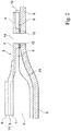
- Fig.1 shows a schematic representation of a fuel cell (10) consisting of a powder metallurgically produced carrier substrate (1) which is porous and gas-permeable in a central region (2) and on the central region (2) a layer stack (11) with chemically active layers is arranged, and a contact plate (6) (interconnector) consists.
- a part of the carrier substrate along the line I-II in Fig.1 is in Fig.2 shown in cross section.
- the carrier substrate (1) is as shown Fig.2 to be more detailed, in the edge region (3) that surrounds the central region, wherein the carrier substrate in the edge region on the cell-facing side on the surface has been aftertreated by a surface processing step that leads to superficial melting.
- the compaction of the edge area is advantageous, but not mandatory.
- the melt phase phase surface portion (4) forms a gas-tight barrier, which extends from the outer periphery of the central region, adjacent to the gas-tight electrolyte (8), to the point where the carrier substrate by means of a weld (12) with the contact plate ( 6) is connected in a gas-tight manner.
- the melting depth is to be measured according to the requirement of gas tightness, a melting depth between 15 microns and 60 microns has been found to be advantageous.
- the residual porosity of the melt phase phase surface portion (4) is extremely low, the porosity of the underlying, not melted region (5) in the edge region is significantly higher than the residual porosity of the melt phase surface portion, the porosity of the unfused edge region is preferably between 4 and 20%.
- the layer stack with chemically active layers is arranged, starting with an anode layer (7), the gas-tight electrolyte layer (8), which extends over a part of the gas-tight edge region for better sealing, and a cathode layer (9).
- the carrier substrate has on two opposite sides in the edge region gas passage openings (14), which serve to supply and discharge of the fuel gas into and out of the fuel gas chamber (13). So that the fuel gas space can be sealed in a gas-tight manner, the surface portion comprising the melt phase extends at least over part of the edge area, which includes gas passage openings provided for the supply and discharge of the process gases (fuel gas and oxide gases).
- a horizontal gas-tight barrier which from the central region to the marginal edges of the gas passage openings, which are provided for the supply and discharge of the process gases, or to the point at which the carrier substrate by means of a weld (12) the contact plate (6) is connected.
- This welded connection can take place along the outer circumference of the carrier substrate, or also, as in FIG Fig.1 shown at a slightly spaced from the outer circumference circumferential line. How out Fig. 2 it can be seen, while the edge of the gas passage openings over the entire thickness of the carrier substrate is melted to form a lateral gas-tight barrier.
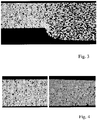
- FIG. 4 show an SEM image of a cross section of a porous carrier substrate with a pressed edge region and detailed views of the pressed edge region before (left) and after (right) a thermal surface treatment step by laser melting.
- a carrier substrate of a sieved powder of an iron-chromium alloy with a particle size less than 125 microns is prepared by conventional powder metallurgy. After sintering, the carrier substrate has a porosity of about 40% by volume.
- the edge area is subsequently compacted by uniaxial pressing, so that a residual porosity of about 7-15% by volume results in the edge area.
- a focused laser beam with a track energy of about 250 J / m is guided over the edge area to be melted and causes a superficial melting of the edge area.
- the focal point of the laser is a Melting zone of about 100 microns depth.
- the surface portion according to the invention forms, which has a melting phase.
- the cross sections are perpendicular to the surface of the plate-shaped carrier substrate.
- a embedding agent for example epoxy resin
- ground after hardening for example with finer sandpaper, respectively.
- the samples are polished with a polishing suspension and finally electrolytically polished.
- these samples are analyzed by means of SEM (scanning electron microscope) and a BSE detector (BSE: back-scattered electrons) (BSE detector or 4-quadrant ring detector). analyzed.
- BSE back-scattered electrons
- BSE detector or 4-quadrant ring detector As a scanning electron microscope while the field emission device “Ultra Pluss 55" Zeiss was used.
- the SEM image is quantitatively evaluated within a measurement area to be evaluated by means of stereological methods (software used: "Leica QWin”), whereby it is ensured that as homogeneous as possible of the part of the carrier substrate is present within the measurement area to be evaluated.
- the area fraction of the pores is determined relative to the total measuring area to be evaluated.
- This area proportion corresponds at the same time to the porosity in% by volume. Pores that lie only partially within the measurement area to be evaluated are not taken into account in the measurement process.
- the following settings were used for the SEM recording: Tilt angle: 0 °, acceleration voltage of 20 kV, working distance of approx. 10 mm and 250x magnification (device specification), resulting in a horizontal image edge of approx. 600 ⁇ m. Special emphasis was placed on a very good image sharpness.
Description
Die Erfindung betrifft ein Trägersubstrat für eine metallgestützte elektrochemische Funktionseinrichtung, ein Herstellungsverfahren für ein derartiges Trägersubstrat und deren Anwendung in Brennstoffzellen.The invention relates to a carrier substrate for a metal-based electrochemical functional device, a manufacturing method for such a carrier substrate and their application in fuel cells.
Ein mögliche Anwendungsgebiet für das erfindungsgemäße Trägersubstrat ist bei Hochtemperatur-Brennstoffzellen (SOFC; solid oxide fuel cell), die typischerweise bei einer Betriebstemperatur von ca. 600-1000°C betrieben werden. In der Basiskonfiguration umfasst die elektrochemisch aktive Zelle einer SOFC einen gasdichten Feststoffelektrolyten, der zwischen einer gasdurchlässigen Anode und gasdurchlässigen Kathode angeordnet ist. Der Feststoffelektrolyt ist dabei meist aus einem festen keramischen Werkstoff aus Metalloxid, der Sauerstoffionen leitet, Elektronen aber nicht. Konzeptionell ist derzeit das planare SOFC System (auch Flachzellenkonzept genannt) das weltweit bevorzugte Zellkonzept. Dabei werden einzelne elektrochemisch aktive Zellen zu einem sogenannten Stack gestapelt und durch metallische Komponenten, sogenannte Interkonnektoren oder Bipolarplatten, verbunden. Bei SOFC Systemen sind aus dem Stand der Technik verschiedene Ausführungsformen bekannt, die im Folgenden kurz skizziert werden sollen. Bei einer ersten Variante, technisch am weitesten fortgeschritten und bereits in der Markteinführungsphase, ist der Elektrolyt die mechanisch tragende Zellkomponente ("Electrolyt Supported Cell", ESC). Die Schichtdicke des Elektrolyten ist hierbei verhältnismäßig groß, ca. 100-150 µm und besteht meist aus Yttriumoxid (YSZ) oder Scandiumoxid (ScSZ) stabilisierten Zirkoniumdioxid. Um eine ausreichende Ionenleiffähigkeit des Elektrolyten zu erzielen müssen diese Brennstoffzellen bei einer verhältnismäßig hohen Betriebstemperatur von ca. 850-1000°C betrieben werden. Diese hohe Betriebstemperatur führt zu hohen Anforderungen an die verwendeten Materialien.
Die Bestrebungen nach niedrigerer Betriebstemperatur führten in Folge zur Entwicklung von unterschiedlichen Dünnschichtsystemen. Dazu zählen Anoden- bzw. Kathoden gestützte ("Anode-Supported Cell" bzw. "Cathodesupported Cell") SOFC Systeme, bei denen ein relativ dickes (mind. ca 200µm) mechanisch tragendes keramisches Anoden- bzw. Kathodensubstrat mit einer dünnen, elektrochemisch aktiven Anoden- bzw. Kathodenfunktionsschicht verbunden ist. Da die Elektrolytschicht keine mechanisch tragende Rolle mehr auszuführen hat, kann diese verhältnismäßig dünn ausgeführt werden und die Betriebstemperatur aufgrund des geringeren ohmschen Widerstands dementsprechend reduziert werden.
Neben diesen rein keramischen Systemen wurden als jüngste Generation SOFC Dünnschichtsysteme entwickelt, die auf einem metallischen Trägersubstrat basieren, sogenannte Metallgestützte SOFC ("Metall-supported Cell", MSC). Diese metallisch-keramischen Verbundsysteme zeigen gegenüber rein keramischen Dünnschichtsystemen Vorteile hinsichtlich der thermischen und redox Zyklierbarkeit sowie der mechanischen Stabilität und können auf Grund ihres Dünnschichtelektrolyten zudem bei einer noch niedrigeren Betriebstemperatur von ca. 600° bis 800°C betrieben werden. Aufgrund ihrer spezifischen Vorteile sind sie insbesondere für mobile Anwendungen, wie beispielsweise zur elektrischen Versorgung von Personenkraftwagen oder Nutzfahrzeugen (APU - auxiliary power unit) geeignet. Im Vergleich zu vollkeramischen SOFC Systemen zeichnen sich die metallisch-keramischen MSC Systeme durch deutlich reduzierte Materialkosten sowie durch neue Möglichkeiten der Stackintegration aus, wie beispielsweise durch Löt- oder Schweißprozesse. Eine exemplarische MSC besteht aus einem ca. 1 mm dicken porösen, dadurch gasdurchlässigen, metallischen Trägersubstrat, auf das eine 60-70µm dicke keramische Verbundstruktur, der eigentlich elektrochemisch aktiven Schichtanordnung mit dem Elektrolyten und den Elektroden, angeordnet ist. Typischerweise ist die Anode dem Trägersubstrat zugewandt und in der Abfolge der Schichtanordnung näher am Metallsubstrat als die Kathode.
Im Betrieb einer SOFC wird der Anode Brennstoff (beispielsweise Wasserstoff oder herkömmliche Kohlenwasserstoffe, wie Methan, Erdgas, Biogas, ...) zugeführt und dort katalytisch unter Abgabe von Elektronen oxidiert. Die Elektronen werden aus der Brennstoffzelle abgeleitet und fließen über einen elektrischen Verbraucher zur Kathode. An der Kathode wird ein Oxidationsmittel (beispielsweise Sauerstoff oder Luft) durch Aufnahme der Elektronen reduziert. Der elektrische Kreislauf schließt sich, indem die Sauerstoffionen über den Elektrolyten zur Anode fließen und an den entsprechenden Grenzflächen mit dem Brennstoff reagieren.One possible field of application for the carrier substrate according to the invention is in the case of high-temperature fuel cells (SOFCs), which are typically operated at an operating temperature of approximately 600-1000 ° C. In the basic configuration, the electrochemically active cell of a SOFC comprises a gas-tight solid electrolyte disposed between a gas-permeable anode and gas-permeable cathode. The solid electrolyte is usually made of a solid ceramic material of metal oxide, which conducts oxygen ions, but not electrons. Conceptually, the planar SOFC system (also known as a flat-cell concept) is currently the preferred cell concept worldwide. In this case, individual electrochemically active cells are stacked into a so-called stack and connected by metallic components, so-called interconnectors or bipolar plates. In SOFC systems, various embodiments are known from the prior art, which are briefly outlined below. In a first variant, technically most advanced and already in the market introduction phase, the electrolyte is the mechanically supporting cell component ("Electrolyte Supported Cell", ESC). The layer thickness of the electrolyte here is relatively large, about 100-150 microns and usually consists of yttria (YSZ) or scandium (ScSZ) stabilized zirconia. In order to achieve a sufficient Ionenleiffähigkeit of the electrolyte, these fuel cells must be operated at a relatively high operating temperature of about 850-1000 ° C. This high operating temperature leads to high demands on the materials used.
Efforts to lower operating temperature resulted in the development of different thin film systems. These include anode-supported or cathode-supported ("anode-supported cell" or "cathode-supported cell") SOFC systems in which a relatively thick (at least about 200 microns) mechanically supporting ceramic anode or cathode substrate with a thin, electrochemically active anode or cathode functional layer is connected. Since the electrolyte layer no longer has to perform a mechanically supporting role, it can be made relatively thin and the operating temperature can be correspondingly reduced due to the lower ohmic resistance.
In addition to these purely ceramic systems, SOFC thin film systems based on a metallic carrier substrate, so-called Metal-Assisted Cell (MSC), have been developed as the latest generation. These metallic-ceramic composite systems show advantages over purely ceramic thin-film systems in terms of thermal and redox cyclability and mechanical stability and can also be operated at a still lower operating temperature of about 600 ° to 800 ° C due to their thin-film electrolyte. Due to their specific advantages, they are particularly suitable for mobile applications, such as for the electrical supply of passenger cars or utility vehicles (APU - auxiliary power unit). Compared to all-ceramic SOFC systems, the metallic-ceramic MSC systems are characterized by significantly reduced material costs and new possibilities of stack integration, such as soldering or welding processes. An exemplary MSC consists of an about 1 mm thick porous, thereby gas-permeable, metallic carrier substrate, on which a 60-70μm thick ceramic composite structure, the actually electrochemically active layer arrangement with the electrolyte and the electrodes, is arranged. Typically, the anode faces the carrier substrate and, in the sequence of the layer assembly, is closer to the metal substrate than the cathode.
During operation of an SOFC, the anode is supplied with fuel (for example hydrogen or conventional hydrocarbons, such as methane, natural gas, biogas, etc.) and is catalytically oxidized there with the emission of electrons. The electrons are derived from the fuel cell and flow via an electrical load to the cathode. At the cathode, an oxidant (eg, oxygen or air) is reduced by receiving the electrons. The electrical circuit closes as the oxygen ions flow across the electrolyte to the anode and react with the fuel at the appropriate interfaces.
Ein herausforderndes Problem bei der Entwicklung von Brennstoffzellen ist die zuverlässige Trennung der beiden Prozessgasräume, also der Trennung des Brennstoffes, der der Anode zugeführt wird, vom Oxidationsmittel, das der Kathode zugeführt wird. Diesbezüglich verspricht die MSC einen großen Vorteil, da mittels Schweiß- oder metallischer Lötprozesse auf kostengünstige Weise Abdichtung und langzeitbeständige Stack-Konzepte realisiert werden können. Eine exemplarische Variante für eine Brennstoffzelleneinheit wird in
Eine Weiterentwicklung stellt die in der
Ein anderer alternativer Ansatz für einen schweißtechnisch integrierbaren MSC Stack basiert auf einem mittig perforierten Blech mit dichtem Randbereich als metallischem Trägersubstrat (
A further development represents the in the
Another alternative approach for a weldable integratable MSC stack is based on a centrally perforated sheet with a dense edge region as a metallic carrier substrate (
Der vorliegenden Erfindung liegt die Aufgabe zugrunde, ein Trägersubstrat der eingangs genannten Art zu schaffen, das beim Einsatz in einer elektrochemischen Funktionseinrichtung, insbesondere in einer Hochtemperatur-Brennstoffzelle, auf einfache und kostengünstige Art und Weise eine zuverlässige Trennung der beiden Prozessgasräume ermöglicht.The present invention has for its object to provide a carrier substrate of the type mentioned above, which enables a reliable separation of the two process gas chambers in a simple and cost-effective manner when used in an electrochemical functional device, in particular in a high-temperature fuel cell.
Diese Aufgabe wird durch die Gegenstände und Verfahren mit den Merkmalen gemäß den unabhängigen Patentansprüchen gelöst.
Gemäß einem Ausführungsbeispiel der vorliegenden Erfindung wird bei einem pulvermetallurgisch hergestellten, plattenförmigen, metallischen Trägersubstrat mit den Merkmalen des Oberbegriffs von Anspruch 1 erfindungsgemäß vorgeschlagen, dass in einem Randbereich des Trägersubstrats ein Oberflächenabschnitt auf der Zell-zugewandten Seite des Trägersubstrats gebildet wird, der eine Schmelzphase des Trägersubstratmaterials aufweist. Erfindungsgemäß weist der unter dem die Schmelzphase aufweisende Oberflächenabschnitt liegende Bereich zumindest abschnittsweise eine höhere Porosität auf als der darüber angeordnete die Schmelzphase aufweisende Oberflächenabschnitt, wobei eine flächige Barriere entlang der Oberfläche des Trägersubstrats gebildet wird. "Zell-zugewandt" bezeichnet dabei jene Seite des Trägersubstrats, an die in einem nachfolgenden Prozessschritt in einem zentralen Bereich des porösen Trägersubstrats ein Schichtstapel mit elektrochemisch aktiven Schichten aufgebracht wird. Normalerweise wird auf das Trägersubstrat die Anode, auf die Anode der gasdichte und sauerstoffionenleitende Elektrolyt und auf den Elektrolyt die Kathode angeordnet. Die Abfolge der Elektrodenschichten kann aber auch umgekehrt sein und der Schichtstapel kann auch noch zusätzliche Funktionsschichten aufweisen, beispielsweise kann zwischen Trägersubstrat und der ersten Elektrodenschicht eine Diffusionsbarriereschicht vorgesehen sein.
Gasdicht bedeutet, dass die Leckrate bei ausreichender Gasdichtigkeit standardmäßig < 10-3 mbar l/cm2 s beträgt (gemessen unter Luft mit Druckanstiegsmethode (Fa. Dr. Wiesner, Remscheid, Typ: Integra DDV) bei einer Druckdifferenz dp = 100 mbar).This object is solved by the objects and methods having the features according to the independent patent claims.
According to one exemplary embodiment of the present invention, in the case of a powder metallurgically produced, plate-shaped, metallic carrier substrate according to the invention, it is proposed that a surface region on the cell-facing side of the carrier substrate is formed in an edge region of the carrier substrate, which forms a melting phase of the carrier Carrier substrate material has. According to the invention, the region lying below the surface portion having the melt phase has, at least in sections, a higher porosity than the surface portion having the melt phase arranged above it, wherein a laminar barrier is formed along the surface of the carrier substrate. "Cell-facing" designates that side of the carrier substrate to which a layer stack with electrochemically active layers is applied in a subsequent process step in a central region of the porous carrier substrate. Normally, the anode is arranged on the carrier substrate, the gas-tight and oxygen-ion-conducting electrolyte on the anode, and the cathode on the electrolyte. However, the sequence of the electrode layers can also be reversed, and the layer stack can also have additional functional layers; for example, a diffusion barrier layer can be provided between the carrier substrate and the first electrode layer.
Gas-tight means that the leakage rate with sufficient gas-tightness is by default <10 -3 mbar l / cm 2 s (measured under air with pressure rise method (Dr. Wiesner, Remscheid, type: Integra DDV) at a pressure difference dp = 100 mbar).
Der erfindungsgemäßen Lösung liegt die Erkenntnis zugrunde, dass es nicht erforderlich ist, wie im Stand der Technik in
Das erfindungsgemäße metallene Trägersubstrat wird pulvermetallurgisch hergestellt und besteht vorzugsweise aus einer Eisen-Chrom Legierung. Das Substrat kann gemäß
Als nächster Schritt erfolgt zumindest auf einem Teil der zell-zugewandten Oberfläche des Randbereichs ein Oberflächenbehandlungsschritt, der zur Bildung einer Schmelzphase aus dem Material des Trägersubstrats in einem Oberflächenabschnitt führt. Der die Schmelzphase aufweisende Oberflächenabschnitt erstreckt sich in der Regel, den Außenumfang des zentralen Bereichs des Trägersubstrats umlaufend, bis an die Außenkanten des Randbereichs, an dem das Trägersubstrat an eine Kontaktplatte, häufig auch als Interkonnektor bezeichnet, gasdicht, beispielsweise durch eine umlaufende Schweißnaht, verbunden wird. Es bildet sich dadurch eine flächige Barriere entlang der Oberfläche des Trägersubstrats, die vom zentralen Bereich des Trägersubstrats, an dem der Schichtstapel mit dem gasdichten Elektrolyten aufgebracht wird, bis zur Schweißnaht, die einen gasdichten Abschluss zum Interkonnektor bildet, reicht.
Ein solcher Oberflächenbehandlungsschritt, der zur oberflächlicher Aufschmelzung führt, kann mittels mechanischer, thermischer oder chemischer Verfahrensschritte erfolgen, beispielsweise mittels Schleifen, Strahlen oder durch Einwirken gebündelter Strahlen von hochenergetischen Photonen, Elektronen, Ionen oder anderer geeigneter fokussierbarer Energiequellen auf die Oberfläche des Randbereichs.
Durch das lokale oberflächliche Aufschmelzen und rasche Abkühlen bildet sich ein verändertes metallisches Gefüge, die Restporosität ist äußerst gering. Das Aufschmelzen kann ein einziges Mal oder auch mehrmals hintereinander erfolgen. Die Aufschmelztiefe ist dabei an das Erfordernis der Gasdichtheit des oberflächennahen Bereichs anzupassen, eine Aufschmelztiefe von mindestens 1 µm, insbesondere 15 µm bis 150 µm, besonders bevorzugt 15 µm bis 60 µm, hat sich als geeignet herausgestellt. Der die Schmelzphase aufweisende Oberflächenabschnitt erstreckt sich daher von der Oberfläche des Trägersubstrats gemessen mindestens 1 µm, insbesondere 15 µm bis 150 µm, besonders bevorzugt 15 µm bis 60 µm, von der Oberfläche ins Trägersubstrat hinein.
Im die Schmelzphase aufweisenden Oberflächenabschnitt können neben der Schmelzphase noch andere Phasen vorliegen, beispielsweise amorphe Strukturen. Besonders bevorzugt ist der die Schmelzphase aufweisenden Oberflächenabschnitt vollständig aus der Schmelzphase des Trägersubstratmaterials gebildet. Der Aufschmelzprozess führt im Randbereich zu einer sehr glatten Oberfläche von geringer Oberflächenrauhigkeit. Dies erlaubt eine gute Beschichtbarkeit für funktionale Schichten wie einer Elektrolytschicht, die, wie nachfolgend beschrieben, optional zur besseren Abdichtung der Prozessgasräume auch über einen Teil des Randbereichs aufgebracht wird.
Um eine durch den Aufschmelzprozess bedingte Schrumpfung des Trägersubstratrandbereichs zu vermindern, kann vor dem Aufschmelzprozess ein Pulver oder eine Pulvermischung aus dem Ausgangsmaterial des Trägersubstrats mit kleiner Partikelgröße zur Füllung der oberflächlichen offenen Poren aufgetragen werden. Im Anschluss daran erfolgt der oberflächliche Aufschmelzprozess. Durch diesen Schritt wird die Maßhaltigkeit der Trägersubstratform verbessert.
Besonders vorteilhaft ist, dass der Randbereich des Trägersubstrats nicht mehr wie nach dem Stand der Technik, beispielsweise
Such a surface treatment step, which leads to superficial melting, can be carried out by means of mechanical, thermal or chemical process steps, for example by means of grinding, blasting or by the effect of focused beams of high-energy photons, electrons, ions or other suitable focusable energy sources on the surface of the edge region.
Due to the local superficial melting and rapid cooling, a modified metallic structure is formed, the residual porosity is extremely low. The melting can be done once or several times in succession. The melting depth is adapted to the requirement of gas tightness of the near-surface region, a melting depth of at least 1 .mu.m, in particular 15 .mu.m to 150 .mu.m, more preferably 15 .mu.m to 60 .mu.m, has been found to be suitable. The surface portion having the melt phase therefore extends from the surface of the carrier substrate measured at least 1 .mu.m, in particular 15 .mu.m to 150 .mu.m, more preferably 15 .mu.m to 60 .mu.m from the surface into the carrier substrate.
In the melt phase having surface portion other phases may be present in addition to the melt phase, such as amorphous structures. Particularly preferably, the surface portion having the melt phase is completely out of the melt phase of Carrier substrate material formed. The melting process leads to a very smooth surface of low surface roughness in the edge region. This allows a good coatability for functional layers such as an electrolyte layer, which, as described below, is optionally applied over a part of the edge region for better sealing of the process gas spaces.
In order to reduce a shrinkage of the carrier substrate edge region caused by the melting process, a powder or a powder mixture of the starting material of the carrier substrate with a small particle size can be applied for filling the superficial open pores prior to the reflow process. This is followed by the superficial melting process. This step improves the dimensional stability of the carrier substrate shape.
It is particularly advantageous that the edge region of the carrier substrate no longer as in the prior art, for
Das erfindungsgemäße Trägersubstrat ist für eine elektrochemische Funktionseinrichtung geeignet, bevorzugt für eine Festelektrolyt-Brennstoffzelle, die eine Betriebstemperatur bis zu 1000°C aufweisen können. Es kann aber auch beispielsweise in der Membrantechnologie zur elektrochemischen Gastrennung eingesetzt werden.The carrier substrate according to the invention is suitable for an electrochemical functional device, preferably for a solid electrolyte fuel cell, which can have an operating temperature of up to 1000 ° C. However, it can also be used for example in membrane technology for electrochemical gas separation.
Im Zuge der Entwicklungen von MSC Systemen wurden verschiedene Ansätze verfolgt, in denen verschiedene Trägersubstratanordnungen mit unterschiedlicher Integrationstiefe zur Anwendung kommen.
Erfindungsgemäß wird für eine erste Variante eine Trägersubstratanordnung vorgeschlagen, die ein erfindungsgemäßes Trägersubstrat aufweist, das von einer Rahmeneinrichtung aus elektrisch leitfähigem Material umfasst wird, wobei die Rahmeneinrichtung das Trägersubstrat elektrisch kontaktiert und die Rahmeneinrichtung mindestens eine Gasdurchtrittsöffnung aufweist. Diese Gasdurchtrittsöffnungen dienen dabei zur Zu- und Abfuhr des Prozessgases, beispielsweise des Brenngases. Ein gasdichter Gasraum wird dadurch geschaffen, dass die Trägersubstratanordnung mit einer Kontaktplatte, die als Interkonnektor wirkt, gasdicht verbunden wird. Durch die Rahmeneinrichtung und den Interkonnektor wird also eine Art Gehäuse gebildet und so ein fluiddichter Prozessgasraum realisiert. Der die Schmelzphase aufweisende Oberflächenabschnitt des Trägersubstrats erstreckt sich dabei vom Außenumfang des zentralen Bereichs bis zu den Außenkanten des Randbereichs bzw. bis zur der Stelle, an der das Trägersubstrat mit der Rahmeneinrichtung durch Schweißen oder Löten verbunden ist.In the course of the development of MSC systems, various approaches have been pursued, in which different carrier substrate arrangements with different levels of integration are used.
According to the invention, a carrier substrate arrangement is proposed for a first variant which has a carrier substrate according to the invention which is comprised of a frame device of electrically conductive material, wherein the frame device electrically contacts the carrier substrate and the frame device has at least one gas passage opening. These gas passage openings serve to supply and discharge of the process gas, for example, the fuel gas. A gas-tight gas space is created in that the carrier substrate arrangement is connected in a gas-tight manner to a contact plate which acts as an interconnector. By the frame means and the interconnector so a kind of housing is formed and realized as a fluid-tight process gas space. The molten phase surface portion of the carrier substrate extends from the outer periphery of the central region to the outer edges of the edge region or to the point at which the carrier substrate is connected to the frame means by welding or soldering.
In einer zweiten Ausführungsform ist das Trägersubstrat und die Rahmeneinrichtung als integraler Bauteil ausgeführt. Mittels Stanzen, Schneiden, Prägen oder vergleichbarer Verfahren werden im Randbereich auf gegenüberliegenden Seiten des plattenförmigen Trägersubstrats Gasdurchtrittsöffnungen gebildet. Diese Öffnungen sind für die Zu- und Abfuhr des Prozessgases, insbesondere des Brenngases vorgesehen. Das Trägersubstrat wird im Randbereich, der Gasdurchtrittsöffnungen aufweist, durch oberflächliches Aufschmelzen nachbehandelt. Der oberflächennachbehandelte Bereich ist dabei so gewählt, dass ein zusammenhängender Abschnitt gebildet wird, der zumindest einen Teil der Gasdurchtrittsöffnungen, bevorzugt jene Öffnungen, die für die Zu- und Ableitung der Prozessgase (Brenn- und Oxidgase) vorgesehen sind, umrandet. Der die Schmelzphase aufweisende Oberflächenabschnitt ist ein zusammenhängender Abschnitt über zumindest einen Teil des Randbereichs und erstreckt sich, den Außenumfang des zentralen Bereichs umlaufend, einerseits bis zu den Kanten der eingeschlossenen Gasdurchtrittsöffnungen, andererseits bis zu den Außenkanten des Randbereichs bzw. bis zur der Stelle, an der das Trägersubstrat mit der Interkonnektorplatte durch Schweißen oder Löten verbunden ist. Um im Randbereich von Gasdurchtrittsöffnungen in vertikaler Richtung über die Dicke des Trägersubstrats Gasdichtheit zu gewährleisten, ist in der Umgebung von Randkanten die Schmelzphase über die gesamte Dicke des Trägersubstrats ausgebildet, d.h. der die Schmelzphase aufweisende Oberflächenabschnitt erstreckt sich am Rand von Gasdurchtrittsöffnungen über die gesamte Dicke des Trägersubstrats bis zur gegenüberliegenden Oberfläche hindurch. Dieses seitliche Abdichten des Trägersubstrats am Rand von Gasdurchtrittsöffnungen wird automatisch erreicht, wenn diese Öffnungen beispielsweise mittels thermischer Prozesse wie Laser-, Elektronen-, Ionen-, Wasserstrahl- oder Reibschneiden gefertigt werden.
Die Erfindung betrifft ferner eine Brennstoffzelle, die eine der erfindungsgemäßen Trägersubstrate bzw. Trägersubstratanordnungen aufweist, wobei ein Schichtstapel mit elektrochemisch aktiven Schichten, insbesondere mit Elektroden-, Elektrolyt,- oder Funktionsschichten, an der Oberfläche des zentralen Bereichs des Trägersubstrats angeordnet ist und eine Elektrolytschicht gasdicht an den fluiddichten oberflächennahen Randbereich angrenzt. Der Schichtstapel kann beispielsweise durchphysikalische Beschichtungsverfahren wie physikalische Dampfabscheidung (PVD), Flammspritzen, Plasmaspritzen oder nasschemische Verfahren wie Siebdruck oder Nasspulverbeschichten aufgebracht werden, auch eine Kombination dieser Verfahren ist denkbar, und neben elektrochemisch aktiven Schichten zusätzliche Funktionsschichten aufweisen. So kann beispielsweise zwischen Trägersubstrat und der ersten Elektrodenschicht, meist einer Anodenschicht, eine Diffusionsbarriereschicht, beispielsweise aus Cer-Gadolinium-Oxid, vorgesehen sein. In einer bevorzugten Ausführungsform kann sich zu einer noch zuverlässigeren Trennung der beiden Prozessgasräume die gasdichte Elektrolytschicht mit ihrem gesamten Umfang zumindest auf einem Teil des fluiddichten oberflächennahen Randbereichs erstrecken, d.h. zumindest über einen Teil des gasdichten Randbereichs gezogen werden. Um eine Brennstoffzelle zu bilden, wird das Trägersubstrat am Umfang gasdicht mit einer Kontaktplatte (Interkonnektor) verbunden. Eine Anordnung mit einer Vielzahl von Brennstoffzellen bildet einen Brennstoffzellenstapel oder ein Brennstoffzellensystem.In a second embodiment, the carrier substrate and the frame device are designed as an integral component. By means of stamping, cutting, embossing or comparable methods, gas passage openings are formed in the edge region on opposite sides of the plate-shaped carrier substrate. These openings are provided for the supply and removal of the process gas, in particular the fuel gas. The carrier substrate is aftertreated by superficial melting in the edge region, which has gas passage openings. The surface-treated area is chosen so that a contiguous portion is formed, which surrounds at least a portion of the gas passage openings, preferably those openings which are provided for the supply and discharge of the process gases (fuel and oxide gases). The molten phase surface portion is a contiguous portion over at least part of the edge portion and extends circumferentially around the outer circumference of the central portion, on the one hand to the edges of the trapped gas passage openings, to the outer edges of the edge portion or to the location, respectively the carrier substrate is connected to the interconnector plate by welding or soldering. In order to ensure gas tightness in the edge region of gas passage openings in the vertical direction over the thickness of the carrier substrate, the melting phase is formed over the entire thickness of the carrier substrate in the vicinity of peripheral edges, ie the surface portion having the melt phase extends at the edge of gas passage openings over the entire thickness of the Carrier substrate through to the opposite surface. This lateral sealing of the Carrier substrate at the edge of gas passage openings is achieved automatically when these openings are made for example by means of thermal processes such as laser, electron, ion, water jet or friction cutting.
The invention further relates to a fuel cell which has one of the carrier substrates or carrier substrate arrangements according to the invention, wherein a layer stack with electrochemically active layers, in particular with electrode, electrolyte, or functional layers, is arranged on the surface of the central region of the carrier substrate and an electrolyte layer is gas-tight adjacent to the fluid-tight near-surface edge region. The layer stack can be applied, for example, by physical coating methods such as physical vapor deposition (PVD), flame spraying, plasma spraying or wet-chemical methods such as screen printing or wet powder coating; a combination of these methods is also conceivable and, in addition to electrochemically active layers, has additional functional layers. For example, a diffusion barrier layer, for example of cerium-gadolinium oxide, can be provided between the carrier substrate and the first electrode layer, usually an anode layer. In a preferred embodiment, for a more reliable separation of the two process gas spaces, the gas-tight electrolyte layer may extend with its entire circumference at least on a part of the fluid-tight, near-surface edge region, ie be pulled over at least part of the gas-tight edge region. In order to form a fuel cell, the carrier substrate is connected to the circumference gas-tight with a contact plate (interconnector). An arrangement with a plurality of fuel cells forms a fuel cell stack or a fuel cell system.
Im Folgenden werden exemplarische Ausführungsbeispiele der vorliegenden Erfindung mit Verweis auf die folgenden Figuren detailliert beschrieben.
- Fig. 1
- zeigt eine perspektivische Explosionsdarstellung einer Brennstoffzelle.
- Fig. 2
- zeigt einen schematischen Querschnitt eines Teils eines beschichteten Trägersubstrat entlang der Linie I-II in
Fig. 1 - Fig. 3
- zeigt einen Querschliff eines Ausschnitts des porösen Trägersubstrats mit verpresstem Randbereich
- Fig. 4
- zeigt Detailansichten des verpressten Randbereichs vor (links) und nach (rechts) einem thermischen Oberflächenbehandlungsschritt.
- Fig. 1
- shows an exploded perspective view of a fuel cell.
- Fig. 2
- shows a schematic cross section of a part of a coated carrier substrate along the line I-II in FIG
Fig. 1 - Fig. 3
- shows a transverse section of a section of the porous carrier substrate with a pressed edge region
- Fig. 4
- shows detailed views of the pressed edge area before (left) and after (right) a thermal surface treatment step.
Ein fokussierter Laserstrahl mit Streckenenergie von etwa 250 J/m wird über den aufzuschmelzenden Randbereich geführt und bewirkt ein oberflächliches Aufschmelzen des Randbereichs. Im Fokuspunkt des Lasers entsteht eine Schmelzzone von etwa 100 µm Tiefe. Nach dem Erstarren bildet sich der erfindungsgemäße Oberflächenabschnitt, der eine Schmelzphase aufweist. Die Querschliffe erfolgen senkrecht zur Oberfläche des plattenförmigen Trägersubstrats. Zur Herstellung eines Querschliffs werden mittels einer Diamantdrahtsäge Teile aus dem Trägersubstrat herausgesägt, diese Teile werden in einem Einbettmittel (beispielsweise Epoxidharz) fixiert und nach Aushärtung geschliffen (sukzessive mit jeweils feinerem Schleifpapier). Anschließend werden die Proben mit einer Poliersuspension poliert und final elektrolytisch poliert.
A focused laser beam with a track energy of about 250 J / m is guided over the edge area to be melted and causes a superficial melting of the edge area. The focal point of the laser is a Melting zone of about 100 microns depth. After solidification, the surface portion according to the invention forms, which has a melting phase. The cross sections are perpendicular to the surface of the plate-shaped carrier substrate. To produce a cross-section, parts are sawn out of the carrier substrate by means of a diamond wire saw, these parts are fixed in a embedding agent (for example epoxy resin) and ground after hardening (successively with finer sandpaper, respectively). Subsequently, the samples are polished with a polishing suspension and finally electrolytically polished.
Zur Bestimmung der Porosität der einzelnen Bereiche des Trägersubstrats werden diese Proben mittels REM (Rasterelektronenmikroskop) und einem BSE-Detetor (BSE: back-scattered-electrons; deutsch: rückgestreute Elektronen) (BSE-Detektor bzw. 4-Quadranten-Ring-Detektor) analysiert. Als Rasterelektronenmikroskop wurde dabei das Feldemissionsgerät "Ultra Pluss 55" der Firma Zeiss verwendet. Die REM-Aufnahme wird innerhalb einer auszuwertenden Messfläche jeweils mittels stereologischer Methoden quantitativ ausgewertet (verwendete Software: "Leica QWin"), wobei darauf geachtet wird, dass innerhalb der auszuwertenden Messfläche ein möglichst homogener Ausschnitt des Teils des Trägersubstrats vorliegt. Im Rahmen der Porositätsmessung wird der Flächenanteil der Poren relativ zu der gesamten, auszuwertenden Messfläche bestimmt. Dieser Flächenanteil entspricht gleichzeitig der Porosität in Vol.-%. Poren, die nur partiell innerhalb der auszuwertenden Messfläche liegen, werden beim Meßverfahren nicht mit berücksichtigt.
Für die REM-Aufnahme wurden folgende Einstellungen verwendet: Kippwinkel: 0°, Beschleunigungsspannung von 20 kV, Arbeitsabstand von ca. 10 mm und 250-fache Vergrößerung (Geräteangabe), was in einer horizontalen Bildkante von etwa 600 µm resultiert. Dabei wurde besonderer Wert auf eine sehr gute Bildschärfe gelegt.To determine the porosity of the individual regions of the carrier substrate, these samples are analyzed by means of SEM (scanning electron microscope) and a BSE detector (BSE: back-scattered electrons) (BSE detector or 4-quadrant ring detector). analyzed. As a scanning electron microscope while the field emission device "Ultra Pluss 55" Zeiss was used. The SEM image is quantitatively evaluated within a measurement area to be evaluated by means of stereological methods (software used: "Leica QWin"), whereby it is ensured that as homogeneous as possible of the part of the carrier substrate is present within the measurement area to be evaluated. Within the scope of the porosity measurement, the area fraction of the pores is determined relative to the total measuring area to be evaluated. This area proportion corresponds at the same time to the porosity in% by volume. Pores that lie only partially within the measurement area to be evaluated are not taken into account in the measurement process.
The following settings were used for the SEM recording: Tilt angle: 0 °, acceleration voltage of 20 kV, working distance of approx. 10 mm and 250x magnification (device specification), resulting in a horizontal image edge of approx. 600 μm. Special emphasis was placed on a very good image sharpness.
Ergänzend ist darauf hinzuweisen, dass Merkmale oder Schritte, die mit Verweis auf eines der obigen Ausführungsbeispiele beschrieben worden sind, auch in Kombination mit anderen Merkmalen oder Schritten anderer oben beschriebener Ausführungsbeispiele verwendet werden können. Bezugszeichen in den Ansprüchen sind nicht als Einschränkung anzusehen.In addition, it should be noted that features or steps that have been described with reference to one of the above embodiments, also in combination with other features or steps of others above described embodiments can be used. Reference signs in the claims are not to be considered as limiting.
Claims (15)
- Plate-shaped, porous, metallic carrier substrate (1) produced by powder metallurgy and intended for a metal-supported electrochemical functional device, comprising a central region (2) and a marginal region (3), it being possible for a layer stack with electrochemically active layers to be arranged on a surface of the central region, on a cell-facing side of the carrier substrate, characterized in that a surface section (4) of the marginal region (3), on the cell-facing side of the carrier substrate, comprises a melt phase of the carrier substrate material, and at least sections of a region (5) located beneath the surface section (4) comprising the melt phase comprise a higher porosity than the surface section (4) arranged above them and comprising the melt phase, wherein an area-shaped barrier is built along the surface.
- Carrier substrate according to Claim 1, characterized in that the marginal region has a higher density and a lower porosity than the central region.
- Carrier substrate according to Claim 1 to 2, characterized in that the surface section comprising the melt phase extends, running around the outer periphery of the central region (2), to the outer edges of the marginal region (3).
- Carrier substrate according to Claim 1 to 3, characterized in that the surface section (4) comprising the melt phase extends into the carrier substrate at least 1 µm from the surface in a direction perpendicular to the cell-facing side of the carrier substrate.
- Carrier substrate according to any of the preceding claims, characterized in that the surface section (4) comprising the melt phase has a residual porosity of not more than 2%.
- Carrier substrate according to any of the preceding claims, characterized in that it is of one-piece form.
- Carrier substrate according to any of the preceding claims, characterized in that the central region has a porosity of 20% to 60% and/or the marginal region (5) has a porosity of less than 20%.
- Carrier substrate according to any of the preceding claims, characterized in that the carrier substrate consists of an Fe-Cr alloy.
- Carrier substrate according to any of the preceding claims, characterized in that the surface section comprising the melt phase extends, in the vicinity of edges of the marginal region, over the entire thickness of the carrier substrate through to the opposite surface.
- Carrier substrate according to any of the preceding claims, characterized in that the marginal region comprises at least one gas passage.
- Carrier substrate arrangement comprising a carrier substrate according to any of Claims 1 to 9, characterized in that the carrier substrate arrangement further comprises a frame device of electrically conductive material, where the frame device electrically contacts the carrier substrate, and the frame device comprises at least one gas passage.
- Fuel cell comprising at least one carrier substrate according to Claim 10 or a carrier substrate arrangement according to Claim 11, in which a layer stack with electrochemically active layers is arranged on the surface of the central region of the carrier substrate, and an electrolyte layer of the electrochemically active layers is formed overlappingly with the surface section comprising the melt phase.
- Method for producing a carrier substrate for a metal-supported, electrochemical functional device, characterized in that said method comprises at least the following steps:• powder-metallurgically producing a plate-shaped carrier substrate comprising a central region and a marginal region, it being possible for a layer stack with electrochemically active layers to be arranged on a surface of the central region, on a cell-facing side of the carrier substrate;• aftertreating at least a part of the marginal region, on the cell-facing side of the carrier substrate, by local, superficial melting, wherein an area-shaped barrier is built along the surface.
- Method according to Claim 13, characterized in that, prior to the superficial melting, at least part of the marginal region is compacted, and so has a lower porosity than the central region of the carrier substrate.
- Method according to Claim 13 or 14, characterized in that a layer stack with electrochemically active layers is applied in the central region of the carrier substrate.
Applications Claiming Priority (2)
| Application Number | Priority Date | Filing Date | Title |
|---|---|---|---|
| DE102013008473.3A DE102013008473A1 (en) | 2013-05-21 | 2013-05-21 | FUEL CELL |
| PCT/EP2014/001219 WO2014187534A1 (en) | 2013-05-21 | 2014-05-07 | Fuel cell |
Publications (2)
| Publication Number | Publication Date |
|---|---|
| EP3000145A1 EP3000145A1 (en) | 2016-03-30 |
| EP3000145B1 true EP3000145B1 (en) | 2017-11-08 |
Family
ID=50771229
Family Applications (1)
| Application Number | Title | Priority Date | Filing Date |
|---|---|---|---|
| EP14725359.5A Not-in-force EP3000145B1 (en) | 2013-05-21 | 2014-05-07 | Fuel cell |
Country Status (10)
| Country | Link |
|---|---|
| US (1) | US20160111732A1 (en) |
| EP (1) | EP3000145B1 (en) |
| JP (1) | JP6360159B2 (en) |
| KR (1) | KR102167852B1 (en) |
| CN (1) | CN105518918B (en) |
| CA (1) | CA2910214A1 (en) |
| DE (1) | DE102013008473A1 (en) |
| DK (1) | DK3000145T3 (en) |
| TW (1) | TWI617673B (en) |
| WO (1) | WO2014187534A1 (en) |
Families Citing this family (7)
| Publication number | Priority date | Publication date | Assignee | Title |
|---|---|---|---|---|
| AT14455U3 (en) * | 2015-07-14 | 2017-05-15 | Plansee Se | Electrochemical module |
| JP6910170B2 (en) * | 2017-03-22 | 2021-07-28 | 大阪瓦斯株式会社 | Substrate with electrode layer for metal-supported electrochemical element, electrochemical element, electrochemical module, electrochemical device, energy system, solid oxide fuel cell, and manufacturing method |
| CN110945698B (en) * | 2017-07-31 | 2020-10-13 | 日产自动车株式会社 | Fuel cell unit |
| EP3830316A1 (en) * | 2018-07-27 | 2021-06-09 | Hoeller Electrolyzer GmbH | Method for producing a porous transport layer for an electrochemical cell |
| DE102019208908A1 (en) * | 2019-06-19 | 2020-12-24 | Robert Bosch Gmbh | Method for manufacturing a fuel cell |
| DE102020203398A1 (en) | 2020-03-17 | 2021-09-23 | Robert Bosch Gesellschaft mit beschränkter Haftung | Process for the additive manufacturing of a metal carrier for a fuel cell |
| CN113067005A (en) * | 2021-03-19 | 2021-07-02 | 东睦新材料集团股份有限公司 | Preparation method of metal support plate for fuel cell |
Family Cites Families (17)
| Publication number | Priority date | Publication date | Assignee | Title |
|---|---|---|---|---|
| JPH10106597A (en) * | 1996-09-25 | 1998-04-24 | Fuji Electric Co Ltd | Solid electrolyte fuel cell |
| WO1998035398A1 (en) * | 1997-02-11 | 1998-08-13 | Bossel Ulf G | Fuel cell stack with solid electrolytes and their arrangement |
| GB2368450B (en) | 2000-10-25 | 2004-05-19 | Imperial College | Fuel cells |
| US6489584B1 (en) * | 2001-05-08 | 2002-12-03 | General Electric Company | Room-temperature surface weld repair of nickel-base superalloys having a nil-ductility range |
| DE10135336C1 (en) * | 2001-07-19 | 2002-11-07 | Elringklinger Ag | Fuel cell unit for fuel cell block has 2 housing parts sealed together via coupling surface parallel to stacking direction of fuel cell units within fuel cell block |
| DE10135333A1 (en) * | 2001-07-19 | 2003-02-06 | Elringklinger Ag | fuel cell unit |
| DE10210293B4 (en) * | 2002-03-08 | 2006-11-23 | Elringklinger Ag | Fuel cell block assembly and method for producing a fuel cell block assembly |
| AT8975U1 (en) | 2006-02-27 | 2007-03-15 | Plansee Se | POROUS BODY |
| JP5172207B2 (en) * | 2006-10-24 | 2013-03-27 | 日本碍子株式会社 | Thin plate for single cell of solid oxide fuel cell |
| US8907248B2 (en) * | 2007-05-03 | 2014-12-09 | Illinois Tool Works Inc. | Aluminum deoxidizing welding wire |
| DE102007024225A1 (en) * | 2007-05-11 | 2008-11-13 | Deutsches Zentrum für Luft- und Raumfahrt e.V. | Support device for an electrochemical functional device, fuel cell module and method for producing a carrier device |
| DE102007034967A1 (en) * | 2007-07-26 | 2009-01-29 | Plansee Se | Fuel cell and process for its production |
| ES2382406T3 (en) * | 2007-10-05 | 2012-06-08 | Topsoe Fuel Cell A/S | Sealing gasket for a porous metal support in a fuel cell |
| MY147805A (en) * | 2008-04-18 | 2013-01-31 | Univ California | Integrated seal for high-temperature electrochemical device |
| DE102008049606A1 (en) * | 2008-09-30 | 2010-04-01 | Siemens Aktiengesellschaft | Porous metal substrate protection method for solvent oxides fuel cell, involves applying protection layer on sintered metal compound, where abrasion and/or polishing of front side of sintered compound is enabled |
| FR2938270B1 (en) * | 2008-11-12 | 2013-10-18 | Commissariat Energie Atomique | METAL OR POROUS METAL ALLOY SUBSTRATE, PROCESS FOR PREPARING THE SAME, AND EHT OR SOFC METAL SUPPORT CELLS COMPRISING THE SUBSTRATE |
| AT14455U3 (en) * | 2015-07-14 | 2017-05-15 | Plansee Se | Electrochemical module |
-
2013
- 2013-05-21 DE DE102013008473.3A patent/DE102013008473A1/en not_active Withdrawn
-
2014
- 2014-04-23 TW TW103114612A patent/TWI617673B/en not_active IP Right Cessation
- 2014-05-07 WO PCT/EP2014/001219 patent/WO2014187534A1/en active Application Filing
- 2014-05-07 KR KR1020157032748A patent/KR102167852B1/en active IP Right Grant
- 2014-05-07 DK DK14725359.5T patent/DK3000145T3/en active
- 2014-05-07 CA CA2910214A patent/CA2910214A1/en not_active Abandoned
- 2014-05-07 JP JP2016514292A patent/JP6360159B2/en not_active Expired - Fee Related
- 2014-05-07 CN CN201480029476.6A patent/CN105518918B/en active Active
- 2014-05-07 US US14/893,163 patent/US20160111732A1/en not_active Abandoned
- 2014-05-07 EP EP14725359.5A patent/EP3000145B1/en not_active Not-in-force
Non-Patent Citations (1)
| Title |
|---|
| None * |
Also Published As
| Publication number | Publication date |
|---|---|
| WO2014187534A1 (en) | 2014-11-27 |
| DK3000145T3 (en) | 2018-02-12 |
| DE102013008473A1 (en) | 2014-11-27 |
| CA2910214A1 (en) | 2014-11-27 |
| KR20160010454A (en) | 2016-01-27 |
| JP2016519413A (en) | 2016-06-30 |
| JP6360159B2 (en) | 2018-07-18 |
| TWI617673B (en) | 2018-03-11 |
| TW201446972A (en) | 2014-12-16 |
| CN105518918B (en) | 2018-08-10 |
| KR102167852B1 (en) | 2020-10-21 |
| US20160111732A1 (en) | 2016-04-21 |
| CN105518918A (en) | 2016-04-20 |
| EP3000145A1 (en) | 2016-03-30 |
Similar Documents
| Publication | Publication Date | Title |
|---|---|---|
| EP3000145B1 (en) | Fuel cell | |
| EP3323168B1 (en) | Electrochemical module | |
| EP2174371B1 (en) | Method for manufacturing a fuel cell | |
| EP2230707A1 (en) | Interconnector of a solid electrolyte high temperature fuel cell | |
| EP2335312A1 (en) | Method for producing an interconnector for high temperature fuel cells, associated high temperature fuel cell and thus built fuel cell assembly | |
| DE102014118358A1 (en) | Single cell with attached separator and fuel cell stack, and method for making a single cell with attached separator | |
| DE102007024227A1 (en) | High-temperature fuel cell module and method for producing a high-temperature fuel cell module | |
| WO2018165682A1 (en) | Porous molded part for electrochemical module | |
| EP3014685B1 (en) | High-temperature cell with a porous gas-conducting channel layer | |
| EP2156499B1 (en) | Method for producing a gas-tight solid electrolyte layer and solid electrolyte layer | |
| DE102008006038B4 (en) | Method for producing a bipolar plate for a fuel cell unit and bipolar plate | |
| WO2021198137A1 (en) | Method for producing a gas- and/or electron-conducting structure and fuel/electrolysis cell | |
| DE102008049712A1 (en) | Planar high-temperature fuel cell | |
| EP2342777A1 (en) | Tubular high-temperature fuel cell, method for the manufacture thereof and fuel cell system comprising the same | |
| EP1658653A1 (en) | Solid-oxide fuel cell and method for producing the same | |
| WO2018165683A1 (en) | Functionalized, porous gas guiding part for an electro-chemical module | |
| WO2018191765A1 (en) | Electrode-electrolyte unit | |
| WO2022048796A1 (en) | Method for producing a green paper for producing a gas diffusion layer for a fuel cell | |
| DE102009037207A1 (en) | Method for connecting bipolar plate with electrode, cathode electrolyte of anode unit and other component of fuel cell stack, involves coating base material of bipolar plate with coating material | |
| EP4154333A1 (en) | Method for producing an electrochemical cell |
Legal Events
| Date | Code | Title | Description |
|---|---|---|---|
| PUAI | Public reference made under article 153(3) epc to a published international application that has entered the european phase |
Free format text: ORIGINAL CODE: 0009012 |
|
| 17P | Request for examination filed |
Effective date: 20151028 |
|
| AK | Designated contracting states |
Kind code of ref document: A1 Designated state(s): AL AT BE BG CH CY CZ DE DK EE ES FI FR GB GR HR HU IE IS IT LI LT LU LV MC MK MT NL NO PL PT RO RS SE SI SK SM TR |
|
| AX | Request for extension of the european patent |
Extension state: BA ME |
|
| RIN1 | Information on inventor provided before grant (corrected) |
Inventor name: ZOBL, GEBHARD Inventor name: RUETTINGER, MATTHIAS Inventor name: KOEGL, MARKUS Inventor name: HAYDN, MARKUS Inventor name: FRANCO, THOMAS |
|
| DAX | Request for extension of the european patent (deleted) | ||
| REG | Reference to a national code |
Ref country code: DE Ref legal event code: R079 Ref document number: 502014006145 Country of ref document: DE Free format text: PREVIOUS MAIN CLASS: H01M0008020000 Ipc: H01M0008023000 |
|
| GRAP | Despatch of communication of intention to grant a patent |
Free format text: ORIGINAL CODE: EPIDOSNIGR1 |
|
| RIC1 | Information provided on ipc code assigned before grant |
Ipc: B23K 26/00 20140101ALI20170517BHEP Ipc: B23K 26/354 20140101ALI20170517BHEP Ipc: H01M 8/023 20160101AFI20170517BHEP Ipc: H01M 8/0245 20160101ALI20170517BHEP Ipc: B22F 3/02 20060101ALI20170517BHEP Ipc: H01M 8/0273 20160101ALI20170517BHEP Ipc: H01M 8/124 20160101ALN20170517BHEP Ipc: B22F 7/00 20060101ALI20170517BHEP Ipc: H01M 8/0232 20160101ALI20170517BHEP Ipc: B22F 3/11 20060101ALI20170517BHEP |
|
| INTG | Intention to grant announced |
Effective date: 20170621 |
|
| GRAS | Grant fee paid |
Free format text: ORIGINAL CODE: EPIDOSNIGR3 |
|
| GRAA | (expected) grant |
Free format text: ORIGINAL CODE: 0009210 |
|
| AK | Designated contracting states |
Kind code of ref document: B1 Designated state(s): AL AT BE BG CH CY CZ DE DK EE ES FI FR GB GR HR HU IE IS IT LI LT LU LV MC MK MT NL NO PL PT RO RS SE SI SK SM TR |
|
| REG | Reference to a national code |
Ref country code: GB Ref legal event code: FG4D Free format text: NOT ENGLISH |
|
| REG | Reference to a national code |
Ref country code: CH Ref legal event code: EP Ref country code: AT Ref legal event code: REF Ref document number: 944967 Country of ref document: AT Kind code of ref document: T Effective date: 20171115 |
|
| REG | Reference to a national code |
Ref country code: IE Ref legal event code: FG4D Free format text: LANGUAGE OF EP DOCUMENT: GERMAN |
|
| REG | Reference to a national code |
Ref country code: DE Ref legal event code: R096 Ref document number: 502014006145 Country of ref document: DE |
|
| REG | Reference to a national code |
Ref country code: DK Ref legal event code: T3 Effective date: 20180207 |
|
| REG | Reference to a national code |
Ref country code: SE Ref legal event code: TRGR |
|
| REG | Reference to a national code |
Ref country code: NL Ref legal event code: MP Effective date: 20171108 |
|
| REG | Reference to a national code |
Ref country code: LT Ref legal event code: MG4D |
|
| PG25 | Lapsed in a contracting state [announced via postgrant information from national office to epo] |
Ref country code: LT Free format text: LAPSE BECAUSE OF FAILURE TO SUBMIT A TRANSLATION OF THE DESCRIPTION OR TO PAY THE FEE WITHIN THE PRESCRIBED TIME-LIMIT Effective date: 20171108 Ref country code: ES Free format text: LAPSE BECAUSE OF FAILURE TO SUBMIT A TRANSLATION OF THE DESCRIPTION OR TO PAY THE FEE WITHIN THE PRESCRIBED TIME-LIMIT Effective date: 20171108 Ref country code: NL Free format text: LAPSE BECAUSE OF FAILURE TO SUBMIT A TRANSLATION OF THE DESCRIPTION OR TO PAY THE FEE WITHIN THE PRESCRIBED TIME-LIMIT Effective date: 20171108 Ref country code: NO Free format text: LAPSE BECAUSE OF FAILURE TO SUBMIT A TRANSLATION OF THE DESCRIPTION OR TO PAY THE FEE WITHIN THE PRESCRIBED TIME-LIMIT Effective date: 20180208 |
|
| REG | Reference to a national code |
Ref country code: FR Ref legal event code: PLFP Year of fee payment: 5 |
|
| PG25 | Lapsed in a contracting state [announced via postgrant information from national office to epo] |
Ref country code: IS Free format text: LAPSE BECAUSE OF FAILURE TO SUBMIT A TRANSLATION OF THE DESCRIPTION OR TO PAY THE FEE WITHIN THE PRESCRIBED TIME-LIMIT Effective date: 20180308 Ref country code: GR Free format text: LAPSE BECAUSE OF FAILURE TO SUBMIT A TRANSLATION OF THE DESCRIPTION OR TO PAY THE FEE WITHIN THE PRESCRIBED TIME-LIMIT Effective date: 20180209 Ref country code: LV Free format text: LAPSE BECAUSE OF FAILURE TO SUBMIT A TRANSLATION OF THE DESCRIPTION OR TO PAY THE FEE WITHIN THE PRESCRIBED TIME-LIMIT Effective date: 20171108 Ref country code: RS Free format text: LAPSE BECAUSE OF FAILURE TO SUBMIT A TRANSLATION OF THE DESCRIPTION OR TO PAY THE FEE WITHIN THE PRESCRIBED TIME-LIMIT Effective date: 20171108 Ref country code: BG Free format text: LAPSE BECAUSE OF FAILURE TO SUBMIT A TRANSLATION OF THE DESCRIPTION OR TO PAY THE FEE WITHIN THE PRESCRIBED TIME-LIMIT Effective date: 20180208 Ref country code: HR Free format text: LAPSE BECAUSE OF FAILURE TO SUBMIT A TRANSLATION OF THE DESCRIPTION OR TO PAY THE FEE WITHIN THE PRESCRIBED TIME-LIMIT Effective date: 20171108 |
|
| PG25 | Lapsed in a contracting state [announced via postgrant information from national office to epo] |
Ref country code: SK Free format text: LAPSE BECAUSE OF FAILURE TO SUBMIT A TRANSLATION OF THE DESCRIPTION OR TO PAY THE FEE WITHIN THE PRESCRIBED TIME-LIMIT Effective date: 20171108 Ref country code: CZ Free format text: LAPSE BECAUSE OF FAILURE TO SUBMIT A TRANSLATION OF THE DESCRIPTION OR TO PAY THE FEE WITHIN THE PRESCRIBED TIME-LIMIT Effective date: 20171108 Ref country code: EE Free format text: LAPSE BECAUSE OF FAILURE TO SUBMIT A TRANSLATION OF THE DESCRIPTION OR TO PAY THE FEE WITHIN THE PRESCRIBED TIME-LIMIT Effective date: 20171108 Ref country code: CY Free format text: LAPSE BECAUSE OF FAILURE TO SUBMIT A TRANSLATION OF THE DESCRIPTION OR TO PAY THE FEE WITHIN THE PRESCRIBED TIME-LIMIT Effective date: 20171108 |
|
| REG | Reference to a national code |
Ref country code: DE Ref legal event code: R097 Ref document number: 502014006145 Country of ref document: DE |
|
| PG25 | Lapsed in a contracting state [announced via postgrant information from national office to epo] |
Ref country code: PL Free format text: LAPSE BECAUSE OF FAILURE TO SUBMIT A TRANSLATION OF THE DESCRIPTION OR TO PAY THE FEE WITHIN THE PRESCRIBED TIME-LIMIT Effective date: 20171108 Ref country code: SM Free format text: LAPSE BECAUSE OF FAILURE TO SUBMIT A TRANSLATION OF THE DESCRIPTION OR TO PAY THE FEE WITHIN THE PRESCRIBED TIME-LIMIT Effective date: 20171108 Ref country code: RO Free format text: LAPSE BECAUSE OF FAILURE TO SUBMIT A TRANSLATION OF THE DESCRIPTION OR TO PAY THE FEE WITHIN THE PRESCRIBED TIME-LIMIT Effective date: 20171108 |
|
| PLBE | No opposition filed within time limit |
Free format text: ORIGINAL CODE: 0009261 |
|
| STAA | Information on the status of an ep patent application or granted ep patent |
Free format text: STATUS: NO OPPOSITION FILED WITHIN TIME LIMIT |
|
| PG25 | Lapsed in a contracting state [announced via postgrant information from national office to epo] |
Ref country code: MT Free format text: LAPSE BECAUSE OF FAILURE TO SUBMIT A TRANSLATION OF THE DESCRIPTION OR TO PAY THE FEE WITHIN THE PRESCRIBED TIME-LIMIT Effective date: 20171108 |
|
| 26N | No opposition filed |
Effective date: 20180809 |
|
| PG25 | Lapsed in a contracting state [announced via postgrant information from national office to epo] |
Ref country code: SI Free format text: LAPSE BECAUSE OF FAILURE TO SUBMIT A TRANSLATION OF THE DESCRIPTION OR TO PAY THE FEE WITHIN THE PRESCRIBED TIME-LIMIT Effective date: 20171108 |
|
| REG | Reference to a national code |
Ref country code: BE Ref legal event code: MM Effective date: 20180531 |
|
| PG25 | Lapsed in a contracting state [announced via postgrant information from national office to epo] |
Ref country code: MC Free format text: LAPSE BECAUSE OF FAILURE TO SUBMIT A TRANSLATION OF THE DESCRIPTION OR TO PAY THE FEE WITHIN THE PRESCRIBED TIME-LIMIT Effective date: 20171108 |
|
| REG | Reference to a national code |
Ref country code: IE Ref legal event code: MM4A |
|
| PG25 | Lapsed in a contracting state [announced via postgrant information from national office to epo] |
Ref country code: LU Free format text: LAPSE BECAUSE OF NON-PAYMENT OF DUE FEES Effective date: 20180507 |
|
| PG25 | Lapsed in a contracting state [announced via postgrant information from national office to epo] |
Ref country code: IE Free format text: LAPSE BECAUSE OF NON-PAYMENT OF DUE FEES Effective date: 20180507 |
|
| PG25 | Lapsed in a contracting state [announced via postgrant information from national office to epo] |
Ref country code: BE Free format text: LAPSE BECAUSE OF NON-PAYMENT OF DUE FEES Effective date: 20180531 |
|
| PG25 | Lapsed in a contracting state [announced via postgrant information from national office to epo] |
Ref country code: TR Free format text: LAPSE BECAUSE OF FAILURE TO SUBMIT A TRANSLATION OF THE DESCRIPTION OR TO PAY THE FEE WITHIN THE PRESCRIBED TIME-LIMIT Effective date: 20171108 |
|
| PG25 | Lapsed in a contracting state [announced via postgrant information from national office to epo] |
Ref country code: PT Free format text: LAPSE BECAUSE OF FAILURE TO SUBMIT A TRANSLATION OF THE DESCRIPTION OR TO PAY THE FEE WITHIN THE PRESCRIBED TIME-LIMIT Effective date: 20171108 |
|
| PG25 | Lapsed in a contracting state [announced via postgrant information from national office to epo] |
Ref country code: HU Free format text: LAPSE BECAUSE OF FAILURE TO SUBMIT A TRANSLATION OF THE DESCRIPTION OR TO PAY THE FEE WITHIN THE PRESCRIBED TIME-LIMIT; INVALID AB INITIO Effective date: 20140507 Ref country code: MK Free format text: LAPSE BECAUSE OF NON-PAYMENT OF DUE FEES Effective date: 20171108 |
|
| PG25 | Lapsed in a contracting state [announced via postgrant information from national office to epo] |
Ref country code: AL Free format text: LAPSE BECAUSE OF FAILURE TO SUBMIT A TRANSLATION OF THE DESCRIPTION OR TO PAY THE FEE WITHIN THE PRESCRIBED TIME-LIMIT Effective date: 20171108 |
|
| PGFP | Annual fee paid to national office [announced via postgrant information from national office to epo] |
Ref country code: DK Payment date: 20200527 Year of fee payment: 7 Ref country code: FI Payment date: 20200522 Year of fee payment: 7 Ref country code: CH Payment date: 20200520 Year of fee payment: 7 Ref country code: FR Payment date: 20200522 Year of fee payment: 7 |
|
| PGFP | Annual fee paid to national office [announced via postgrant information from national office to epo] |
Ref country code: SE Payment date: 20200527 Year of fee payment: 7 Ref country code: IT Payment date: 20200528 Year of fee payment: 7 Ref country code: GB Payment date: 20200527 Year of fee payment: 7 |
|
| PGFP | Annual fee paid to national office [announced via postgrant information from national office to epo] |
Ref country code: AT Payment date: 20200522 Year of fee payment: 7 |
|
| REG | Reference to a national code |
Ref country code: FI Ref legal event code: MAE |
|
| REG | Reference to a national code |
Ref country code: DK Ref legal event code: EBP Effective date: 20210531 |
|
| REG | Reference to a national code |
Ref country code: SE Ref legal event code: EUG |
|
| REG | Reference to a national code |
Ref country code: CH Ref legal event code: PL |
|
| REG | Reference to a national code |
Ref country code: AT Ref legal event code: MM01 Ref document number: 944967 Country of ref document: AT Kind code of ref document: T Effective date: 20210507 |
|
| GBPC | Gb: european patent ceased through non-payment of renewal fee |
Effective date: 20210507 |
|
| PG25 | Lapsed in a contracting state [announced via postgrant information from national office to epo] |
Ref country code: LI Free format text: LAPSE BECAUSE OF NON-PAYMENT OF DUE FEES Effective date: 20210531 Ref country code: CH Free format text: LAPSE BECAUSE OF NON-PAYMENT OF DUE FEES Effective date: 20210531 Ref country code: AT Free format text: LAPSE BECAUSE OF NON-PAYMENT OF DUE FEES Effective date: 20210507 Ref country code: FI Free format text: LAPSE BECAUSE OF NON-PAYMENT OF DUE FEES Effective date: 20210507 Ref country code: SE Free format text: LAPSE BECAUSE OF NON-PAYMENT OF DUE FEES Effective date: 20210508 |
|
| PG25 | Lapsed in a contracting state [announced via postgrant information from national office to epo] |
Ref country code: GB Free format text: LAPSE BECAUSE OF NON-PAYMENT OF DUE FEES Effective date: 20210507 Ref country code: DK Free format text: LAPSE BECAUSE OF NON-PAYMENT OF DUE FEES Effective date: 20210531 |
|
| PG25 | Lapsed in a contracting state [announced via postgrant information from national office to epo] |
Ref country code: FR Free format text: LAPSE BECAUSE OF NON-PAYMENT OF DUE FEES Effective date: 20210531 |
|
| PGFP | Annual fee paid to national office [announced via postgrant information from national office to epo] |
Ref country code: DE Payment date: 20220519 Year of fee payment: 9 |
|
| PG25 | Lapsed in a contracting state [announced via postgrant information from national office to epo] |
Ref country code: IT Free format text: LAPSE BECAUSE OF NON-PAYMENT OF DUE FEES Effective date: 20200507 |
|
| REG | Reference to a national code |
Ref country code: DE Ref legal event code: R119 Ref document number: 502014006145 Country of ref document: DE |