EP2999952B1 - Techniken zur überwachung eines getriebezustands - Google Patents
Techniken zur überwachung eines getriebezustands Download PDFInfo
- Publication number
- EP2999952B1 EP2999952B1 EP14801722.1A EP14801722A EP2999952B1 EP 2999952 B1 EP2999952 B1 EP 2999952B1 EP 14801722 A EP14801722 A EP 14801722A EP 2999952 B1 EP2999952 B1 EP 2999952B1
- Authority
- EP
- European Patent Office
- Prior art keywords
- frequencies
- monitored
- lifting equipment
- closed
- data
- Prior art date
- Legal status (The legal status is an assumption and is not a legal conclusion. Google has not performed a legal analysis and makes no representation as to the accuracy of the status listed.)
- Active
Links
Images


Classifications
-
- G—PHYSICS
- G01—MEASURING; TESTING
- G01M—TESTING STATIC OR DYNAMIC BALANCE OF MACHINES OR STRUCTURES; TESTING OF STRUCTURES OR APPARATUS, NOT OTHERWISE PROVIDED FOR
- G01M13/00—Testing of machine parts
- G01M13/02—Gearings; Transmission mechanisms
- G01M13/021—Gearings
-
- G—PHYSICS
- G01—MEASURING; TESTING
- G01H—MEASUREMENT OF MECHANICAL VIBRATIONS OR ULTRASONIC, SONIC OR INFRASONIC WAVES
- G01H1/00—Measuring characteristics of vibrations in solids by using direct conduction to the detector
- G01H1/003—Measuring characteristics of vibrations in solids by using direct conduction to the detector of rotating machines
- G01H1/006—Measuring characteristics of vibrations in solids by using direct conduction to the detector of rotating machines of the rotor of turbo machines
-
- G—PHYSICS
- G01—MEASURING; TESTING
- G01P—MEASURING LINEAR OR ANGULAR SPEED, ACCELERATION, DECELERATION, OR SHOCK; INDICATING PRESENCE, ABSENCE, OR DIRECTION, OF MOVEMENT
- G01P3/00—Measuring linear or angular speed; Measuring differences of linear or angular speeds
- G01P3/42—Devices characterised by the use of electric or magnetic means
- G01P3/44—Devices characterised by the use of electric or magnetic means for measuring angular speed
-
- H—ELECTRICITY
- H02—GENERATION; CONVERSION OR DISTRIBUTION OF ELECTRIC POWER
- H02P—CONTROL OR REGULATION OF ELECTRIC MOTORS, ELECTRIC GENERATORS OR DYNAMO-ELECTRIC CONVERTERS; CONTROLLING TRANSFORMERS, REACTORS OR CHOKE COILS
- H02P29/00—Arrangements for regulating or controlling electric motors, appropriate for both AC and DC motors
- H02P29/02—Providing protection against overload without automatic interruption of supply
- H02P29/032—Preventing damage to the motor, e.g. setting individual current limits for different drive conditions
Definitions
- the present invention relates to predicting gear failure in connection with electrical motors driven by motor drives.
- prediction of gear failure comprises two tasks, namely monitoring gear condition and detecting potentially risky changes in the gear condition.
- JP05069923B2 discloses techniques for a hoist crane with a diagnosis apparatus that calculates diagnosing value of abrasion of gear wheel based on variations in electric current flowing into motor and rotation angle value of shaft when gear wheel meshes with a motor.
- An operation control apparatus controls drive of an electric motor and a rotation angle detection apparatus linked to rotating shaft of the motor.
- a current sensor measures variation in electric current flowing into the motor and the rotation angle detection apparatus detects variation in rotation angle of the shaft when the gear wheel meshes with motor.
- An abrasion diagnosis apparatus calculates diagnosing value of abrasion of gear wheel based on variations in electric current value and rotation angle value.
- a prior art US Patent Application Publication US 2012/0126738 A1 discloses a prior art system and method for rotating machinery condition monitoring.
- the condition monitoring of the rotating machinery during operation at either constant or variable speed is performed using data from a feedback position sensor.
- the position signals, obtained as pulses, are converted into a time-dependent velocity signal which is then transformed into the frequency domain.
- the frequency of signal components identified by spectral analysis is compared against known frequencies which indicate the presence of certain faults, including, but not limited to, bearing faults, gear faults, or a load imbalance.
- the patent document does not teach the monitoring of the gear condition of lifting equipment.
- a prior art US Patent Application Publication US 2012/0203497 A1 discloses a prior art device and method for detecting and identifying a damaged gear among connected gears of a copier or image forming apparatus.
- mesh frequencies of the gears are selected for their ability to indicate which gear among the connected gears is about to cause problems.
- the disclosed solution also uses the time evolution of spectral frequencies derived from a feedback speed signal used for the speed control of the electrical drive of the copier - changes in the mesh frequencies correlate with impending faults in the gear mechanism of the copier.
- the patent document also does not teach the monitoring of the gear condition of lifting equipment.
- a prior art EP Patent Application Publication EP 1405047 B1 relates generally to the vibration analysis of machinery including lifting equipment such as winders or cranes, for the purposes of predictive maintenance.
- the document discloses the use of accelerometers for monitoring the vibrations of a gearbox of a friction winder. Detected changes over time of the vibration signatures in the frequency domain are used to provide alarms indicating imminent faults.
- the document does not disclose the use of speed feedback signal obtained from a speed sensor used as input for the speed control unit of an electrical motor in closed-loop configuration.
- a problem with the prior art is the extensive instrumentation required to measure the currents and to detect the various rotation angles with sufficient precision, resolution and repeatability. While it may be feasible to provide new equipment with such additional sensors and connections, retrofitting existing equipment is difficult, labor-intensive and expensive.
- the invention is based on the idea of using information that exists in a system comprising an electrical motor and a motor drive, preferably in a closed-loop configuration. It was a hypothesis by the inventors that:
- Embodiments of the invention aim at monitoring condition, particularly relating to wear, of the system being monitored by methods or equipments according to embodiments of the invention.
- embodiments of the invention aim at reducing additional instrumentation, such as additional sensors and cabling, which are used for monitoring wear in many of the prior art techniques.
- the invention offers a number of advantages over known vibration-sensing techniques. Unlike techniques which are based on sensing of mechanical vibrations, the present invention can be used without acceleration sensors or cabling for them. Likewise, the present invention can be used without a separate sensor for producing a trigger pulse for starting or synchronizing the measurement. In addition to eliminating the need for acceleration sensor and cabling thereto, the present invention eliminates some of their associated disadvantages, such as the sensitivity to vibration from external sources.
- Embodiments of the invention are utilized in lifting equipment that comprise at least one speed output unit and an electric motor.
- a non-exhaustive list of examples of such lifting equipment includes cranes, hoists, lifts (elevators), escalators, pumps or windmills.
- a motor drive refers to a device or unit that controls one or more aspects of the power feed to the electric motor.
- a motor drive typically comprises a frequency converter, a variable frequency drive or a pulse-width modulator.
- the speed output unit can be a dedicated speed detector, such as a pulse sensor that outputs a number of pulses for each revolution of a rotating shaft. As an illustrative but non-restrictive example, the pulse sensor may output 600 pulses per revolution for sufficient resolution.
- the electrical motor is driven by a motor drive, in which case the speed feedback signal can be delivered to the motor drive.
- Speed feedback signal is given by the speed sensor 2-10.
- the motor drive and the electric motor are arranged into a closed-loop configuration, in which case an observed difference between a set speed and an actual speed may be utilized for additional information.
- actual speed is measured and used as a speed feedback signal for the motor drive.
- the invention is thus at least partially based on the surprising fact that observation of change in frequency components of the rotational speed over time yields valuable information on the condition of the system.
- the same measured speed or a derivative thereof is utilized for the purposes of the inventive condition monitoring, whereby the need for additional sensors and cabling is reduced or eliminated altogether.
- the act of detecting changes has several possible implementations, such as detection of one or more frequencies at which the amplitude exceeds a certain threshold; a relative change exceeds a certain threshold; or the rate of the change exceeds a certain threshold.
- an alert condition is indicated if at least one detected change between the corresponding frequencies exceeds a predetermined threshold.
- the method may comprise indicating an alert condition if at least one detected change between the corresponding frequencies exceeds an average change computed over several other changes.
- Some implementations comprise scaling the first and second frequencies to a common frequency if the frequencies were obtained at different speeds.
- the step of maintaining data that indicates a set of predictor frequencies at which the detected changes correlate with wear better than at randomly selected frequencies. Changes at the predictor frequencies may be weighted more strongly than changes at other frequencies.
- said comparing the sets of monitored frequencies comprises a cepstrum conversion of each of the first and second set of monitored frequencies.
- said monitoring the first and second set of frequencies comprises monitoring a set value and an actual value of the electrical motor in a closed-loop configuration.
- the analysis in the frequency domain comprises conversion to a cepstrum.
- a cepstrum is the result of taking the Fourier transform (FT) of the logarithm of the estimated spectrum of a signal.
- FT Fourier transform
- a benefit of the cepstrum conversion is that harmonic overtones are reduced to their base frequencies. For instance, if a given source of vibration is known to vibrate at, say, 5.5 Hz, and the vibration is not purely sinusoidal, harmonic overtones of n*5.5 Hz, n being an integer > 1, are also generated from the same source. Reducing the harmonic overtones to their base frequencies simplifies the task of detecting vibration sources whose condition has changed over time.
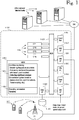
- Figure 1 shows an exemplary data processing architecture that can be programmed to perform the various data processing tasks relating to embodiments of the invention.
- the data processing architecture will be referred to as a computer, but those skilled in the art will realize that the data processing architecture need not be implemented as a dedicated computer. Instead, several embedded techniques are possible, as are techniques in which the inventive functionality is installed on a data processing system that exists for other purposes.
- the architecture of the computer comprises one or more central processing units CP1 ... CPn, generally denoted by reference numeral 1-110.
- Embodiments comprising multiple processing units 1-110 are preferably provided with a load balancing unit 1-115 that balances processing load among the multiple processing units 1-110.
- the multiple processing units 1-110 may be implemented as separate processor components or as physical processor cores or virtual processors within a single component case.
- the computer architecture 1-100 comprises a network interface 1-120 for communicating with various data networks, which are generally denoted by reference sign DN.
- the data networks DN may include local-area networks, such as an Ethernet network, and/or wide-area networks, such as the internet.
- the computer architecture may comprise a wireless network interface, generally denoted by reference numeral 1-125.
- the computer 1-100 may communicate with various access networks AN, such as cellular networks or Wireless Local-Area Networks (WLAN).
- WLAN Wireless Local-Area Networks
- Other forms of wireless communications include short-range wireless techniques, such as Bluetooth and various "Bee" interfaces, such as ZigBee or its some of its proprietary implementations.
- the computer architecture 1-100 may also comprise a local user interface 1-140.
- the user interface 1-140 may comprise local input-output circuitry for a local user interface, such as a keyboard, mouse and display (not shown).
- the computer architecture also comprises memory 1-150 for storing program instructions, operating parameters and variables.
- Reference numeral 1-160 denotes a program suite for the server computer 1-100.
- the computer architecture 1-100 also comprises circuitry for various clocks, interrupts and the like, and these are generally depicted by reference numeral 1-130.
- the computer architecture 1-100 further comprises a storage interface 1-145 to a storage system 1-190.
- the storage system 1-190 comprises non-volatile storage, such as a magnetically, optically or magneto-optically rewritable disk and/or non-volatile semiconductor memory, commonly referred to as Solid State Drive (SSD) or Flash memory.
- SSD Solid State Drive
- the storage system 1-190 may store the software that implements the processing functions, and on power-up, the software is read into semiconductor memory 1-150.
- the storage system 1-190 also retains operating data and variables over power-off periods.
- the various elements 1-110 through 1-150 intercommunicate via a bus 1-105, which carries address signals, data signals and control signals, as is well known to those skilled in the art.
- Reference number 1-135 denotes an interface by which the computer 1-100 obtains data from the system that includes an electric motor and a speed output unit.
- a specific implementation of such a system, which includes an electric motor and a motor drive in a closed-loop configuration will be shown in Figure 2 .
- a speed output unit In an open-loop configuration, a speed output unit must be provided separately. It is self-evident that the nature of interface for the speed output unit, depends on the nature of the speed output unit itself. A non-exhaustive list of common examples includes CAN, Profibus, Serial interfaces (eg HMI protocol over physical RS-232 interface), or the like.
- the inventive techniques may be implemented in the computer architecture 1-100 as follows.
- the program suite 1-160 comprises program code instructions for instructing the processor or set of processors 1-110 to execute the functions of the invention or its embodiments, including:
- the memory 1-160 stores instructions for carrying out normal system or operating system functions, such as resource allocation, inter-process communication, or the like.
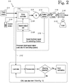
- Figure 2 illustrates an embodiment of a system that includes an electric motor and a speed output unit.
- the implementation shown in Figure 2 comprises a motor drive in a closed-loop speed control configuration.
- Block 2-2 which is drawn with a dashed outline, depicts the closed-loop speed control configuration.
- Reference number 2-4 denotes a power supply configured to supply power via a motor drive 2-6 to a motor 2-8.
- the motor drive 2-6 comprises a drive controller 2-6A and a speed output unit 2-6B.
- Motor speed is monitored by a speed sensor 2-10 that provides a speed feedback signal 2-12 to the motor drive 2-6.
- the speed feedback signal 2-12 is typically, but not exclusively, formed as a pulse sequence.
- the speed output unit 2-6B processes the speed feedback signal 2-12 primarily for the purpose of motor speed control in a closed-loop configuration.
- the processed speed feedback signal denoted by reference sign 2-12' is also branched off to a condition monitoring unit CMU.
- CMU condition monitoring unit
- Figure 17 illustrates an external condition monitoring unit.
- the functionality of the condition monitoring unit can equally well be integrated into the controller of the motor drive.
- the signal 2-12' branced off from the closed-loop motor configuration to the condition monitoring unit CMU may already be in an advantegeous format for processing by the CMU.
- an advantegeous format may be or comprise a rotational speed sampled at equal intervals.
- the signal is preferably a digital signal.
- the speed control configuration can be controlled from a wired or wireless control device, generally denoted by reference number 2-14.
- the motor 2-8 drives a gear 2-16.
- the gear 2-16 in turn drives a hoist 2-18, which in this example raises or lowers a load 2-20.
- load movement may be unidirectional.
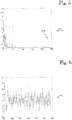
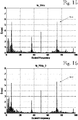
- Figures 3 and 4 show measurement results in frequency domain (diagram 3-2) and time domain(diagram 4-2), respectively, at the beginning of a test.
- Figures 5 and 6 show measurement results in frequency domain (diagram 5-2) and time domain(diagram 6-2), respectively, at the end of the test.
- peak heights vary greatly for different frequencies.
- the peak at 234 Hz denoted by reference numbers 3-12 and 3-12', has increased significantly towards the end of the test.
- some new visible peaks have appeared at frequencies between 0 and 30 Hz.
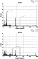
- Figures 7 and 8 show respective spectra 7-2 and 8-2.
- the spectra show that some of the low-frequency peaks exhibit significant increases between the beginning and the end of the test.
- the inventors have discovered that these low-frequency peaks are relevant failure indicators for the particular gear that was used for the tests.
- the calculated failure frequencies are listed in Table 1. Frequencies that can be obtained from speed measurement plotted in the frequency domain are indicated by > or >> signs. Single > signs indicate good matches and double >> signs indicate very good matches. A good match exists between the calculated and measured frequencies, and there is no doubt that the gear condition has changed during the test. Even relatively small frequency peaks can be detected by this methodology.
- the above table 1 gives the frequencies on the basis of mechanical specifications. In environments wherein the key frequencies cannot be obtained from mechanical specifications.
- the frequencies can be obtained empirically. For instance, a measurement is started and data is collected for a while. Frequencies whose amplitudes increase or which are distinguished by some other means will be selected for long-time observation. After an interval, which is experimentally known to be long enough for significant changes to appear, the measurement is repeated, and the measured frequencies before the interval ("the first frequencies") and after the interval (“the second frequencies”) are compared to detect new or increased peaks. The data collection and comparison is repeated at a rate which is experimentally known to be sufficiently high to detect significant changes before actual equipment failure. When one or more frequencies with significant changes are detected, it is beneficial for the condition monitoring unit to adapt its monitoring scheme, eg, by taking observations at an increased rate.
- Figure 9 shows some of these frequencies, generally denoted by reference number 9-2, in timeline format during the test, which ran for eight to nine hours per day. Measurements were taken twice per day, three individual measurements at both times. Near the end of the test, the test ran continuously. This measurement anomaly explains the sharp rises for many frequencies near the end of the test. In this test, significant changes between the beginning and the end of the test was detected at frequencies 8.7 Hz, 9.8 Hz, 11 Hz, and 14.9 Hz.
- Figure 10 shows a plot of shaft speed 10-2 and unfiltered motor currency 10-4 vs. time over the course of a test run.
- the immediate purpose of this test was to find out how the variation of speed affects the analysis and its results.
- a more far-reaching purpose was to develop algorithms and/or identify characteristic frequencies that detect wear and/or predict failure in gear systems regardless of the speeds and loads used.
- Figures 11 through 16 illustrate data scalability with six different speeds ranging from 50 to 75 Hz at 5 Hz apart. An equal load (5 tons) was used at all speeds.
- reference number 11-2 denotes a peak caused by a mass-spring effect generated by the load and ropes
- reference number 11-4 denotes the speed of the drive itself in Hz.
- Figures 11 through 16 were obtained at speeds of 50, 55, 60, 65, 70 and 75 Hz, all results have been presented with scaled frequencies. Accordingly, the peak 11-4, which is caused by the varying drive speed, always occurs at the 50-Hz mark.
- reference number 12-6 denotes a resonance frequency
- FIG 17 shows a software architecture that was used in a working protototype, which is called a Condition Monitoring Unit ("CMU") in the following.
- the CMU denoted by reference number 17-6, was coupled to a D2V drive 17-2 manufactured by the owner of the present application.
- the drive 17-2 is a part of an example of the equipment whose condition is being monitored.
- the drive may also receive information from an actual speed output unit 17-4.
- the inventive principle is adaptable to other types of drives by using routine skills.
- the in-built data logger of the D2V drive is set to collect the correct signals.
- the data logger trigs and starts to collect data. It is beneficial to collect data during an even or nearly even run. Measurements can be made, for instance, by storing the speed output signal continuously. Measurements can be repeated periodically or when triggered by other considerations, for instance in cases where changes have been made to the system or its operating conditions, and the rate can be increased (period shortened) when significant changes are detected. When enough data have been collected, it is transferred to the condition monitoring unit CMU for data processing (17-8).
- the eligibility of the data is checked, and if the data is correct, it will be processed for detecting possible wear of the gear (17-10). If the CMU 17-6 detects in test 17-12 that the wear condition exceeds certain given limits, it will initiate sending a notification or alarm to a remote center or operator (17-14) to investigate the matter. The data will be saved for further study (17-16). After that, the CMU 17-6 is in standby mode for the next measurement. If no signs of wearing are detected, no alarm is sent, and the data logger is prepared for the next measurement. Even in cases where no alarm condition is detected, the data may be saved for further study and/or confirmation purposes. In the prototype phase, the data processing was not yet implemented in the CMU, so decisions on actual alert conditions was not done by the CMU. Nevertheless, studies carried out so far have confirmed the hypothesis of the inventors that monitoring progress of frequency peaks over time in a closed-loop motor drive configuration can yield data capable of indicating wear condition and/or predicting failure in a gear system, even without installation of additional sensors.
- measurements can be made whenever an opportunity is detected. If no significant changes from the previous measurement are detected, the raw data can be deleted and only a log entry is made, indicating that results were substantially similar to a previous measurement.
Landscapes
- Physics & Mathematics (AREA)
- General Physics & Mathematics (AREA)
- Engineering & Computer Science (AREA)
- Power Engineering (AREA)
- Control Of Electric Motors In General (AREA)
- Testing Of Devices, Machine Parts, Or Other Structures Thereof (AREA)
Claims (9)
- Verfahren zum Überwachen des Getriebezustands einer Hebevorrichtung (2-2), umfassend das Durchführen der folgenden Handlungen in Bezug auf die Hebevorrichtung (2-2), die einen Elektromotor (2-8) und eine Drehzahlausgabeeinheit (2-10) umfasst, und dem Elektromotor (2-8) folgt ein Getriebe (2-16), wobei der Elektromotor (2-8) von einem Motorantrieb (2-6) angetrieben wird und der Elektromotor (2-8) und der Motorantrieb (2-6) sich in einer Konfiguration mit geschlossenem Regelkreis befinden und der Motorantrieb (2-6) ein Drehzahlrückkopplungssignal (2-12) mit geschlossenem Regelkreis zur Steuerung des Elektromotors (2-8) verwendet, wobei bei diesem Verfahren die folgenden Handlungen von einem Datenverarbeitungssystem (1-100) durchgeführt werden, das betriebsmäßig mit der Hebevorrichtung (2-2) gekoppelt ist;- Überwachen eines ersten Satzes von Frequenzen (3-2, 4-2) von der Hebevorrichtung (2-2) über eine Messperiode, wenn sich die Hebevorrichtung (2-2) in einem bekannten guten Betriebszustand befindet;- Speichern des ersten Satzes von überwachten Frequenzen oder Ableitungen davon als Referenzdaten in einem Langzeitspeichersystem;- Überwachen eines zweiten Satzes von Frequenzen (5-2, 6-2) von der Hebevorrichtung (2-2) über eine Messperiode, wenn sich die Hebevorrichtung (2-2) in einem unbekannten Betriebszustand befindet;- Vergleichen des zweiten Satzes von überwachten Frequenzen mit dem ersten Satz von überwachten Frequenzen in einem Frequenzbereich;- im Frequenzbereich, Erkennen von Abweichungen zwischen entsprechenden Frequenzen (3-12, 3-12'), die sich aus dem zweiten Satz von überwachten Frequenzen und dem ersten Satz von überwachten Frequenzen ergeben;- Angeben eines Alarmzustands, wenn mindestens eine erkannte Abweichung zwischen den entsprechenden Frequenzen einen vorgegebenen Schwellenwert überschreitet; und- Beibehalten von Daten, die einen Satz von Prädiktorfrequenzen angeben, bei denen die erkannten Abweichungen besser mit dem Verschleiß korrelieren als bei zufällig ausgewählten Frequenzen;- wobei zumindest einige des ersten Satzes von überwachten Frequenzen und des zweiten Satzes von überwachten Frequenzen aus dem Drehzahlrückkopplungssignal (2-12) oder seiner Ableitung (2-12') erlangt werden, wobei das Drehzahlrückkopplungssignal (2-12) oder seine Ableitung (2-12') Informationen über die Drehzahl über die Zeit des Elektromotors (2-8) umfasst, wobei die Drehzahlinformationen in gleichen Intervallen abgetastet werden.
- Verfahren nach Anspruch 1, ferner umfassend das Skalieren der Frequenzen auf eine gemeinsame Frequenz, wenn die Spitzenwerte des ersten Satzes überwachter Frequenzen und die Spitzenwerte des zweiten Satzes überwachter Frequenzen bei unterschiedlichen Drehzahlen erlangt wurden.
- Verfahren nach Anspruch 1 oder 2, ferner umfassend das stärkere Gewichten von Abweichungen bei den Prädiktorfrequenzen als von Abweichungen bei anderen Frequenzen.
- Verfahren nach einem der vorstehenden Ansprüche, ferner umfassend das Erhöhen einer Überwachungsrate für den zweiten Satz von Frequenzen als Reaktion darauf, dass eine oder mehrere der Abweichungen einen Satz von Signifikanzkriterien erfüllen.
- Verfahren nach einem der vorstehenden Ansprüche, wobei das Vergleichen des zweiten Satzes von überwachten Frequenzen mit dem ersten Satz von überwachten Frequenzen in einem Frequenzbereich eine Cepstrumumwandlung von jedem des ersten und des zweiten Satzes von überwachten Frequenzen umfasst.
- Verfahren nach einem der vorstehenden Ansprüche, wobei der erste Satz von überwachten Frequenzen und der zweite Satz von überwachten Frequenzen Frequenzspitzen im Frequenzbereich umfassen.
- Verfahren nach Anspruch 1, wobei das Datenverarbeitungssystem (1-100, 17-6) in eine Steuerung des Motorantriebs (2-6) des Hebesystems integriert ist.
- Hebevorrichtung umfassend einen Motorantrieb (2-6), einen Elektromotor (2-8) und eine Drehzahlausgabeeinheit (2-10) in einer Konfiguration mit geschlossenem Regelkreis, wobei die Hebevorrichtung ein Datenverarbeitungssystem (1-100, 17-6) umfasst; wobei das Datenverarbeitungssystem umfasst:- ein Speichersystem (1-150) zum Speichern von Programmcodeanweisungen und Daten;- ein Verarbeitungssystem (1-110) mit mindestens einer Verarbeitungseinheit, wobei das Verarbeitungssystem mindestens einen Teil der Programmcodeanweisungen ausführt und die Daten verarbeitet;- und wobei der Elektromotor (2-8) von dem Motorantrieb (2-6) angetrieben wird und der Elektromotor (2-8) und der Motorantrieb (2-6) sich in einer Konfiguration mit geschlossenem Regelkreis befinden und der Motorantrieb (2-6) ein Drehzahlrückkopplungssignal (2-12) mit geschlossenem Regelkreis zur Steuerung des Elektromotors (2-8) verwendet;wobei das Speichersystem Programmcodeanweisungen speichert, die, wenn sie von dem Verarbeitungssystem ausgeführt werden, das Verarbeitungssystem anweisen, die folgenden Handlungen auszuführen:- Überwachen eines ersten Satzes von Frequenzen (3-2, 4-2) von der Hebevorrichtung (2-2) über eine Messperiode, wenn sich die Hebevorrichtung (2-2) in einem bekannten guten Betriebszustand befindet;- Speichern des ersten Satzes von überwachten Frequenzen oder Ableitungen davon als Referenzdaten in einem Langzeitspeichersystem;- Überwachen eines zweiten Satzes von Frequenzen (5-2, 6-2) von der Hebevorrichtung (2-2) über eine Messperiode, wenn sich die Hebevorrichtung (2-2) in einem unbekannten Betriebszustand befindet;- Vergleichen des zweiten Satzes von überwachten Frequenzen mit dem ersten Satz von überwachten Frequenzen in einem Frequenzbereich;- im Frequenzbereich, Erkennen von Abweichungen zwischen entsprechenden Frequenzen (3-12, 3-12'), die sich aus dem zweiten Satz von überwachten Frequenzen und dem ersten Satz von überwachten Frequenzen ergeben;- wobei ein Alarmzustand angegeben wird, wenn mindestens eine erkannte Abweichung zwischen den entsprechenden Frequenzen einen vorgegebenen Schwellenwert überschreitet; und- wobei Daten beibehalten werden, wobei die Daten einen Satz von Prädiktorfrequenzen angeben, bei denen die erkannten Abweichungen besser mit dem Verschleiß korrelieren als bei zufällig ausgewählten Frequenzen;- wobei zumindest einige des ersten Satzes von überwachten Frequenzen und des zweiten Satzes von überwachten Frequenzen aus dem Drehzahlrückkopplungssignal (2-12) oder seiner Ableitung (2-12') erlangt werden, wobei das Drehzahlrückkopplungssignal (2-12) oder seine Ableitung (2-12') Informationen über die Drehzahl über die Zeit des Elektromotors (2-8) umfasst, wobei die Drehzahlinformationen in gleichen Intervallen abgetastet werden.
- Datenverarbeitungssystem nach Anspruch 8, wobei das Datenverarbeitungssystem (1-100, 17-6) in eine Steuerung des Motorantriebs (2-6) des Motorantriebs integriert ist.
Applications Claiming Priority (3)
| Application Number | Priority Date | Filing Date | Title |
|---|---|---|---|
| FI20135546 | 2013-05-21 | ||
| FI20135567A FI20135567L (fi) | 2013-05-24 | 2013-05-24 | Tekniikoita vaihteen kunnon valvomiseksi |
| PCT/FI2014/050390 WO2014188072A1 (en) | 2013-05-21 | 2014-05-21 | Techniques for monitoring gear condition |
Publications (3)
| Publication Number | Publication Date |
|---|---|
| EP2999952A1 EP2999952A1 (de) | 2016-03-30 |
| EP2999952A4 EP2999952A4 (de) | 2017-01-18 |
| EP2999952B1 true EP2999952B1 (de) | 2021-09-01 |
Family
ID=51933009
Family Applications (1)
| Application Number | Title | Priority Date | Filing Date |
|---|---|---|---|
| EP14801722.1A Active EP2999952B1 (de) | 2013-05-21 | 2014-05-21 | Techniken zur überwachung eines getriebezustands |
Country Status (6)
| Country | Link |
|---|---|
| US (2) | US9863845B2 (de) |
| EP (1) | EP2999952B1 (de) |
| CN (1) | CN105378445B (de) |
| AU (1) | AU2014270291B2 (de) |
| ES (1) | ES2893828T3 (de) |
| WO (1) | WO2014188072A1 (de) |
Families Citing this family (9)
| Publication number | Priority date | Publication date | Assignee | Title |
|---|---|---|---|---|
| BRPI0923419B1 (pt) | 2008-12-22 | 2020-05-19 | Spm Instr Ab | aparelho e método para analizar a condição de uma máquina, e, programa de computador. |
| WO2014042582A1 (en) | 2012-09-11 | 2014-03-20 | S.P.M. Instrument Ab | Apparatus for monitoring the condition of a machine |
| DE102014101654B4 (de) * | 2014-02-11 | 2017-10-05 | Konecranes Global Corporation | Hebezeug mit Hysteresekupplung |
| US10498193B2 (en) * | 2016-12-15 | 2019-12-03 | Kinematics, Llc. | Driven gear diagnostic system and method |
| JP6909131B2 (ja) * | 2017-11-09 | 2021-07-28 | 住友重機械工業株式会社 | 寿命予測システム |
| US11423711B2 (en) * | 2018-05-15 | 2022-08-23 | Robert Bosch Automotive Steering Llc | Force-based corrosion detection for vehicle steering rack |
| FR3093768B1 (fr) * | 2019-03-13 | 2021-07-02 | Safran Aircraft Engines | Procédé et système de surveillance d’un état d’un réducteur d’une turbine à gaz |
| CN110132578B (zh) * | 2019-06-01 | 2019-12-24 | 吉林大学 | 一种齿轮系统复合故障特征提取方法及故障试验装置 |
| CN115980445B (zh) * | 2022-12-12 | 2025-10-21 | 广西电网有限责任公司电力科学研究院 | 一种基于倒谱分析的基频电能质量故障嵌入式检测方法 |
Citations (1)
| Publication number | Priority date | Publication date | Assignee | Title |
|---|---|---|---|---|
| EP1405047A1 (de) * | 2001-07-09 | 2004-04-07 | Shell Internationale Researchmaatschappij B.V. | Vibrationsanalyse zur prädiktiven wartung an maschinen |
Family Cites Families (14)
| Publication number | Priority date | Publication date | Assignee | Title |
|---|---|---|---|---|
| DE4017448A1 (de) | 1989-06-05 | 1990-12-06 | Siemens Ag | Verfahren zur diagnose der mechanischen eigenschaften von maschinen |
| US5115671A (en) | 1990-07-13 | 1992-05-26 | Life Systems, Inc. | Method and apparatus for analyzing rotating machines |
| US5501105A (en) | 1991-10-02 | 1996-03-26 | Monitoring Technology Corp. | Digital signal processing of encoder signals to detect resonances in rotating machines |
| US5610339A (en) | 1994-10-20 | 1997-03-11 | Ingersoll-Rand Company | Method for collecting machine vibration data |
| US6326758B1 (en) * | 1999-12-15 | 2001-12-04 | Reliance Electric Technologies, Llc | Integrated diagnostics and control systems |
| US6445995B1 (en) | 2001-01-26 | 2002-09-03 | General Electric Company | Vibration sensing in gas turbine engine |
| ATE321997T1 (de) * | 2002-01-18 | 2006-04-15 | Spm Instr Ab | Analysesystem |
| CN1791822A (zh) * | 2003-05-20 | 2006-06-21 | 卢西德有限公司 | 用于对患者身体所选位置进行成像的共焦显微镜 |
| JP5069923B2 (ja) | 2007-02-28 | 2012-11-07 | 株式会社日立産機システム | 異常診断機能付きホイストクレーン装置 |
| US9964430B2 (en) | 2009-05-05 | 2018-05-08 | S.P.M. Instrument Ab | Apparatus and a method for analyzing the vibration of a machine having a rotating part |
| US9008997B2 (en) * | 2009-10-26 | 2015-04-14 | Fluke Corporation | System and method for vibration analysis and phase analysis of vibration waveforms using dynamic statistical averaging of tachometer data to accurately calculate rotational speed |
| US8810173B2 (en) * | 2010-11-18 | 2014-08-19 | Rockwell Automation Technologies, Inc. | Rotating machinery condition monitoring using position sensor |
| JP2012181185A (ja) * | 2011-02-08 | 2012-09-20 | Ricoh Co Ltd | 検知装置、画像形成装置、プログラムおよび検知システム |
| EP2581724B1 (de) * | 2011-10-13 | 2020-03-25 | Moventas Gears Oy | Verfahren und System zur Zustandsüberwachung von Getriebegehäusen |
-
2014
- 2014-05-21 ES ES14801722T patent/ES2893828T3/es active Active
- 2014-05-21 EP EP14801722.1A patent/EP2999952B1/de active Active
- 2014-05-21 US US14/892,916 patent/US9863845B2/en active Active
- 2014-05-21 AU AU2014270291A patent/AU2014270291B2/en active Active
- 2014-05-21 CN CN201480029408.XA patent/CN105378445B/zh active Active
- 2014-05-21 WO PCT/FI2014/050390 patent/WO2014188072A1/en not_active Ceased
-
2017
- 2017-12-04 US US15/830,720 patent/US10393622B2/en active Active
Patent Citations (1)
| Publication number | Priority date | Publication date | Assignee | Title |
|---|---|---|---|---|
| EP1405047A1 (de) * | 2001-07-09 | 2004-04-07 | Shell Internationale Researchmaatschappij B.V. | Vibrationsanalyse zur prädiktiven wartung an maschinen |
Also Published As
| Publication number | Publication date |
|---|---|
| US20180088003A1 (en) | 2018-03-29 |
| CN105378445B (zh) | 2018-10-26 |
| EP2999952A4 (de) | 2017-01-18 |
| ES2893828T3 (es) | 2022-02-10 |
| US20160091394A1 (en) | 2016-03-31 |
| EP2999952A1 (de) | 2016-03-30 |
| AU2014270291A1 (en) | 2015-12-03 |
| US9863845B2 (en) | 2018-01-09 |
| WO2014188072A1 (en) | 2014-11-27 |
| CN105378445A (zh) | 2016-03-02 |
| AU2014270291B2 (en) | 2016-08-11 |
| US10393622B2 (en) | 2019-08-27 |
Similar Documents
| Publication | Publication Date | Title |
|---|---|---|
| EP2999952B1 (de) | Techniken zur überwachung eines getriebezustands | |
| US8893858B2 (en) | Method and system for determining safety of elevator | |
| EP1760311B1 (de) | Verfahren und Vorrichtung zur betriebsabhängigen Überwachung der Unterteilen einer Windenergieanlage | |
| CN105692383B (zh) | 电梯故障诊断装置、方法以及控制器 | |
| US9913006B1 (en) | Power-efficient data-load-efficient method of wirelessly monitoring rotating machines | |
| US20150227122A1 (en) | Predictive maintenance method and system | |
| RU2725832C1 (ru) | Система и способ сбора операционных данных о вибрации для горной машины | |
| EP3822216B1 (de) | Überwachungssystem für eine fahrtreppe und verfahren dafür | |
| WO2017145222A1 (ja) | 軸受劣化診断装置、軸受劣化診断方法及び軸受劣化診断システム | |
| JP2012171763A (ja) | エレベータの制御装置及び感知器 | |
| KR20210144147A (ko) | 타워크레인 진단 시스템 및 방법 | |
| JP2008254876A (ja) | エレベータの診断運転装置及び診断運転方法 | |
| EP3404502A1 (de) | Zustandsbasierte instandhaltung einer vorrichtung | |
| WO2017072172A1 (en) | Sensor-monitored drive engine arrangement for an elevator system | |
| CN117514642A (zh) | 偏航制动系统异常监测方法、装置、电子设备及存储介质 | |
| CN105928611A (zh) | 机械设备故障预警系统及方法 | |
| CN103148162B (zh) | 振动自稳控制方法、装置和系统、以及起重机 | |
| CN202962688U (zh) | 离心机的保护设备 | |
| JP6806287B2 (ja) | 温度推移特定装置、保守計画システム及びエレベーターシステム | |
| JP7028394B2 (ja) | 状態監視システム | |
| CN105314487A (zh) | 电梯的保养方法以及电梯系统 | |
| KR20140086269A (ko) | 베어링 잔여 수명 예측 방법 | |
| US20190323923A1 (en) | Electric drive unit having intelligent maintenance requirement montoring | |
| JP2018060383A (ja) | 処理装置及び機器の制御システム | |
| KR102609725B1 (ko) | 함정 부품의 관리 방법 및 관리 시스템 |
Legal Events
| Date | Code | Title | Description |
|---|---|---|---|
| PUAI | Public reference made under article 153(3) epc to a published international application that has entered the european phase |
Free format text: ORIGINAL CODE: 0009012 |
|
| 17P | Request for examination filed |
Effective date: 20151217 |
|
| AK | Designated contracting states |
Kind code of ref document: A1 Designated state(s): AL AT BE BG CH CY CZ DE DK EE ES FI FR GB GR HR HU IE IS IT LI LT LU LV MC MK MT NL NO PL PT RO RS SE SI SK SM TR |
|
| AX | Request for extension of the european patent |
Extension state: BA ME |
|
| DAX | Request for extension of the european patent (deleted) | ||
| A4 | Supplementary search report drawn up and despatched |
Effective date: 20161220 |
|
| RIC1 | Information provided on ipc code assigned before grant |
Ipc: G01M 13/02 20060101AFI20161214BHEP Ipc: G01R 23/18 20060101ALI20161214BHEP Ipc: H02K 7/116 20060101ALI20161214BHEP Ipc: H02P 29/032 20160101ALN20161214BHEP Ipc: G01P 3/44 20060101ALN20161214BHEP Ipc: G01H 1/00 20060101ALI20161214BHEP Ipc: G01M 1/14 20060101ALI20161214BHEP |
|
| STAA | Information on the status of an ep patent application or granted ep patent |
Free format text: STATUS: EXAMINATION IS IN PROGRESS |
|
| 17Q | First examination report despatched |
Effective date: 20180226 |
|
| RIN1 | Information on inventor provided before grant (corrected) |
Inventor name: MESIAE, HEIKKI Inventor name: KEROVUORI, JUHANI Inventor name: HARRA, ILKKA Inventor name: SALOMAEKI, JANNE Inventor name: JANTUNEN, AAPO |
|
| GRAP | Despatch of communication of intention to grant a patent |
Free format text: ORIGINAL CODE: EPIDOSNIGR1 |
|
| STAA | Information on the status of an ep patent application or granted ep patent |
Free format text: STATUS: GRANT OF PATENT IS INTENDED |
|
| RIC1 | Information provided on ipc code assigned before grant |
Ipc: H02P 29/032 20160101ALN20210305BHEP Ipc: G01P 3/44 20060101ALN20210305BHEP Ipc: G01M 13/021 20190101ALI20210305BHEP Ipc: G01R 23/18 20060101ALI20210305BHEP Ipc: G01H 1/00 20060101ALI20210305BHEP Ipc: H02K 7/116 20060101ALI20210305BHEP Ipc: G01M 1/14 20060101ALI20210305BHEP Ipc: G01M 13/02 20190101AFI20210305BHEP |
|
| INTG | Intention to grant announced |
Effective date: 20210326 |
|
| GRAS | Grant fee paid |
Free format text: ORIGINAL CODE: EPIDOSNIGR3 |
|
| GRAA | (expected) grant |
Free format text: ORIGINAL CODE: 0009210 |
|
| STAA | Information on the status of an ep patent application or granted ep patent |
Free format text: STATUS: THE PATENT HAS BEEN GRANTED |
|
| AK | Designated contracting states |
Kind code of ref document: B1 Designated state(s): AL AT BE BG CH CY CZ DE DK EE ES FI FR GB GR HR HU IE IS IT LI LT LU LV MC MK MT NL NO PL PT RO RS SE SI SK SM TR |
|
| REG | Reference to a national code |
Ref country code: GB Ref legal event code: FG4D |
|
| REG | Reference to a national code |
Ref country code: CH Ref legal event code: EP Ref country code: AT Ref legal event code: REF Ref document number: 1426710 Country of ref document: AT Kind code of ref document: T Effective date: 20210915 |
|
| REG | Reference to a national code |
Ref country code: DE Ref legal event code: R096 Ref document number: 602014079867 Country of ref document: DE |
|
| REG | Reference to a national code |
Ref country code: IE Ref legal event code: FG4D |
|
| REG | Reference to a national code |
Ref country code: FI Ref legal event code: FGE |
|
| REG | Reference to a national code |
Ref country code: SE Ref legal event code: TRGR |
|
| REG | Reference to a national code |
Ref country code: NL Ref legal event code: FP |
|
| REG | Reference to a national code |
Ref country code: LT Ref legal event code: MG9D |
|
| PG25 | Lapsed in a contracting state [announced via postgrant information from national office to epo] |
Ref country code: LT Free format text: LAPSE BECAUSE OF FAILURE TO SUBMIT A TRANSLATION OF THE DESCRIPTION OR TO PAY THE FEE WITHIN THE PRESCRIBED TIME-LIMIT Effective date: 20210901 Ref country code: BG Free format text: LAPSE BECAUSE OF FAILURE TO SUBMIT A TRANSLATION OF THE DESCRIPTION OR TO PAY THE FEE WITHIN THE PRESCRIBED TIME-LIMIT Effective date: 20211201 Ref country code: NO Free format text: LAPSE BECAUSE OF FAILURE TO SUBMIT A TRANSLATION OF THE DESCRIPTION OR TO PAY THE FEE WITHIN THE PRESCRIBED TIME-LIMIT Effective date: 20211201 Ref country code: HR Free format text: LAPSE BECAUSE OF FAILURE TO SUBMIT A TRANSLATION OF THE DESCRIPTION OR TO PAY THE FEE WITHIN THE PRESCRIBED TIME-LIMIT Effective date: 20210901 Ref country code: RS Free format text: LAPSE BECAUSE OF FAILURE TO SUBMIT A TRANSLATION OF THE DESCRIPTION OR TO PAY THE FEE WITHIN THE PRESCRIBED TIME-LIMIT Effective date: 20210901 |
|
| REG | Reference to a national code |
Ref country code: ES Ref legal event code: FG2A Ref document number: 2893828 Country of ref document: ES Kind code of ref document: T3 Effective date: 20220210 |
|
| PG25 | Lapsed in a contracting state [announced via postgrant information from national office to epo] |
Ref country code: PL Free format text: LAPSE BECAUSE OF FAILURE TO SUBMIT A TRANSLATION OF THE DESCRIPTION OR TO PAY THE FEE WITHIN THE PRESCRIBED TIME-LIMIT Effective date: 20210901 Ref country code: LV Free format text: LAPSE BECAUSE OF FAILURE TO SUBMIT A TRANSLATION OF THE DESCRIPTION OR TO PAY THE FEE WITHIN THE PRESCRIBED TIME-LIMIT Effective date: 20210901 Ref country code: GR Free format text: LAPSE BECAUSE OF FAILURE TO SUBMIT A TRANSLATION OF THE DESCRIPTION OR TO PAY THE FEE WITHIN THE PRESCRIBED TIME-LIMIT Effective date: 20211202 |
|
| PG25 | Lapsed in a contracting state [announced via postgrant information from national office to epo] |
Ref country code: IS Free format text: LAPSE BECAUSE OF FAILURE TO SUBMIT A TRANSLATION OF THE DESCRIPTION OR TO PAY THE FEE WITHIN THE PRESCRIBED TIME-LIMIT Effective date: 20220101 Ref country code: SM Free format text: LAPSE BECAUSE OF FAILURE TO SUBMIT A TRANSLATION OF THE DESCRIPTION OR TO PAY THE FEE WITHIN THE PRESCRIBED TIME-LIMIT Effective date: 20210901 Ref country code: SK Free format text: LAPSE BECAUSE OF FAILURE TO SUBMIT A TRANSLATION OF THE DESCRIPTION OR TO PAY THE FEE WITHIN THE PRESCRIBED TIME-LIMIT Effective date: 20210901 Ref country code: RO Free format text: LAPSE BECAUSE OF FAILURE TO SUBMIT A TRANSLATION OF THE DESCRIPTION OR TO PAY THE FEE WITHIN THE PRESCRIBED TIME-LIMIT Effective date: 20210901 Ref country code: PT Free format text: LAPSE BECAUSE OF FAILURE TO SUBMIT A TRANSLATION OF THE DESCRIPTION OR TO PAY THE FEE WITHIN THE PRESCRIBED TIME-LIMIT Effective date: 20220103 Ref country code: EE Free format text: LAPSE BECAUSE OF FAILURE TO SUBMIT A TRANSLATION OF THE DESCRIPTION OR TO PAY THE FEE WITHIN THE PRESCRIBED TIME-LIMIT Effective date: 20210901 Ref country code: CZ Free format text: LAPSE BECAUSE OF FAILURE TO SUBMIT A TRANSLATION OF THE DESCRIPTION OR TO PAY THE FEE WITHIN THE PRESCRIBED TIME-LIMIT Effective date: 20210901 Ref country code: AL Free format text: LAPSE BECAUSE OF FAILURE TO SUBMIT A TRANSLATION OF THE DESCRIPTION OR TO PAY THE FEE WITHIN THE PRESCRIBED TIME-LIMIT Effective date: 20210901 |
|
| REG | Reference to a national code |
Ref country code: DE Ref legal event code: R097 Ref document number: 602014079867 Country of ref document: DE |
|
| PLBE | No opposition filed within time limit |
Free format text: ORIGINAL CODE: 0009261 |
|
| STAA | Information on the status of an ep patent application or granted ep patent |
Free format text: STATUS: NO OPPOSITION FILED WITHIN TIME LIMIT |
|
| PG25 | Lapsed in a contracting state [announced via postgrant information from national office to epo] |
Ref country code: DK Free format text: LAPSE BECAUSE OF FAILURE TO SUBMIT A TRANSLATION OF THE DESCRIPTION OR TO PAY THE FEE WITHIN THE PRESCRIBED TIME-LIMIT Effective date: 20210901 |
|
| 26N | No opposition filed |
Effective date: 20220602 |
|
| PG25 | Lapsed in a contracting state [announced via postgrant information from national office to epo] |
Ref country code: SI Free format text: LAPSE BECAUSE OF FAILURE TO SUBMIT A TRANSLATION OF THE DESCRIPTION OR TO PAY THE FEE WITHIN THE PRESCRIBED TIME-LIMIT Effective date: 20210901 |
|
| REG | Reference to a national code |
Ref country code: AT Ref legal event code: UEP Ref document number: 1426710 Country of ref document: AT Kind code of ref document: T Effective date: 20210901 |
|
| REG | Reference to a national code |
Ref country code: CH Ref legal event code: PL |
|
| PG25 | Lapsed in a contracting state [announced via postgrant information from national office to epo] |
Ref country code: MC Free format text: LAPSE BECAUSE OF FAILURE TO SUBMIT A TRANSLATION OF THE DESCRIPTION OR TO PAY THE FEE WITHIN THE PRESCRIBED TIME-LIMIT Effective date: 20210901 Ref country code: LU Free format text: LAPSE BECAUSE OF NON-PAYMENT OF DUE FEES Effective date: 20220521 Ref country code: LI Free format text: LAPSE BECAUSE OF NON-PAYMENT OF DUE FEES Effective date: 20220531 Ref country code: CH Free format text: LAPSE BECAUSE OF NON-PAYMENT OF DUE FEES Effective date: 20220531 |
|
| PG25 | Lapsed in a contracting state [announced via postgrant information from national office to epo] |
Ref country code: IE Free format text: LAPSE BECAUSE OF NON-PAYMENT OF DUE FEES Effective date: 20220521 |
|
| P01 | Opt-out of the competence of the unified patent court (upc) registered |
Effective date: 20230428 |
|
| PG25 | Lapsed in a contracting state [announced via postgrant information from national office to epo] |
Ref country code: HU Free format text: LAPSE BECAUSE OF FAILURE TO SUBMIT A TRANSLATION OF THE DESCRIPTION OR TO PAY THE FEE WITHIN THE PRESCRIBED TIME-LIMIT; INVALID AB INITIO Effective date: 20140521 |
|
| PG25 | Lapsed in a contracting state [announced via postgrant information from national office to epo] |
Ref country code: MK Free format text: LAPSE BECAUSE OF FAILURE TO SUBMIT A TRANSLATION OF THE DESCRIPTION OR TO PAY THE FEE WITHIN THE PRESCRIBED TIME-LIMIT Effective date: 20210901 Ref country code: CY Free format text: LAPSE BECAUSE OF FAILURE TO SUBMIT A TRANSLATION OF THE DESCRIPTION OR TO PAY THE FEE WITHIN THE PRESCRIBED TIME-LIMIT Effective date: 20210901 |
|
| PG25 | Lapsed in a contracting state [announced via postgrant information from national office to epo] |
Ref country code: MT Free format text: LAPSE BECAUSE OF FAILURE TO SUBMIT A TRANSLATION OF THE DESCRIPTION OR TO PAY THE FEE WITHIN THE PRESCRIBED TIME-LIMIT Effective date: 20210901 |
|
| PGFP | Annual fee paid to national office [announced via postgrant information from national office to epo] |
Ref country code: NL Payment date: 20250522 Year of fee payment: 12 |
|
| PGFP | Annual fee paid to national office [announced via postgrant information from national office to epo] |
Ref country code: FI Payment date: 20250520 Year of fee payment: 12 |
|
| PGFP | Annual fee paid to national office [announced via postgrant information from national office to epo] |
Ref country code: DE Payment date: 20250519 Year of fee payment: 12 |
|
| PGFP | Annual fee paid to national office [announced via postgrant information from national office to epo] |
Ref country code: GB Payment date: 20250522 Year of fee payment: 12 Ref country code: ES Payment date: 20250616 Year of fee payment: 12 |
|
| PGFP | Annual fee paid to national office [announced via postgrant information from national office to epo] |
Ref country code: BE Payment date: 20250520 Year of fee payment: 12 Ref country code: IT Payment date: 20250530 Year of fee payment: 12 |
|
| PGFP | Annual fee paid to national office [announced via postgrant information from national office to epo] |
Ref country code: FR Payment date: 20250526 Year of fee payment: 12 |
|
| PGFP | Annual fee paid to national office [announced via postgrant information from national office to epo] |
Ref country code: AT Payment date: 20250519 Year of fee payment: 12 |
|
| PGFP | Annual fee paid to national office [announced via postgrant information from national office to epo] |
Ref country code: SE Payment date: 20250522 Year of fee payment: 12 |
|
| PG25 | Lapsed in a contracting state [announced via postgrant information from national office to epo] |
Ref country code: TR Free format text: LAPSE BECAUSE OF FAILURE TO SUBMIT A TRANSLATION OF THE DESCRIPTION OR TO PAY THE FEE WITHIN THE PRESCRIBED TIME-LIMIT Effective date: 20210901 |