EP2998616A1 - Dispositif de transmission à changement de vitesse et transmission pour véhicule de type à selle - Google Patents
Dispositif de transmission à changement de vitesse et transmission pour véhicule de type à selle Download PDFInfo
- Publication number
- EP2998616A1 EP2998616A1 EP15185053.4A EP15185053A EP2998616A1 EP 2998616 A1 EP2998616 A1 EP 2998616A1 EP 15185053 A EP15185053 A EP 15185053A EP 2998616 A1 EP2998616 A1 EP 2998616A1
- Authority
- EP
- European Patent Office
- Prior art keywords
- side member
- shift
- input
- gear
- output
- Prior art date
- Legal status (The legal status is an assumption and is not a legal conclusion. Google has not performed a legal analysis and makes no representation as to the accuracy of the status listed.)
- Granted
Links
- 230000005540 biological transmission Effects 0.000 title claims abstract description 100
- 238000006073 displacement reaction Methods 0.000 claims abstract description 33
- 238000001514 detection method Methods 0.000 claims abstract description 21
- 238000003825 pressing Methods 0.000 claims abstract description 20
- 230000007935 neutral effect Effects 0.000 claims abstract description 18
- 238000006243 chemical reaction Methods 0.000 claims abstract description 17
- 238000004519 manufacturing process Methods 0.000 abstract description 5
- 230000009467 reduction Effects 0.000 abstract description 5
- 230000007246 mechanism Effects 0.000 description 11
- 230000006835 compression Effects 0.000 description 7
- 238000007906 compression Methods 0.000 description 7
- 230000000694 effects Effects 0.000 description 5
- 230000008859 change Effects 0.000 description 3
- 230000009194 climbing Effects 0.000 description 2
- 238000005520 cutting process Methods 0.000 description 2
- 230000008901 benefit Effects 0.000 description 1
- 238000005304 joining Methods 0.000 description 1
- 230000004048 modification Effects 0.000 description 1
- 238000012986 modification Methods 0.000 description 1
Images


Classifications
-
- F—MECHANICAL ENGINEERING; LIGHTING; HEATING; WEAPONS; BLASTING
- F16—ENGINEERING ELEMENTS AND UNITS; GENERAL MEASURES FOR PRODUCING AND MAINTAINING EFFECTIVE FUNCTIONING OF MACHINES OR INSTALLATIONS; THERMAL INSULATION IN GENERAL
- F16H—GEARING
- F16H63/00—Control outputs from the control unit to change-speed- or reversing-gearings for conveying rotary motion or to other devices than the final output mechanism
- F16H63/40—Control outputs from the control unit to change-speed- or reversing-gearings for conveying rotary motion or to other devices than the final output mechanism comprising signals other than signals for actuating the final output mechanisms
- F16H63/50—Signals to an engine or motor
- F16H63/502—Signals to an engine or motor for smoothing gear shifts
-
- F—MECHANICAL ENGINEERING; LIGHTING; HEATING; WEAPONS; BLASTING
- F16—ENGINEERING ELEMENTS AND UNITS; GENERAL MEASURES FOR PRODUCING AND MAINTAINING EFFECTIVE FUNCTIONING OF MACHINES OR INSTALLATIONS; THERMAL INSULATION IN GENERAL
- F16H—GEARING
- F16H59/00—Control inputs to control units of change-speed-, or reversing-gearings for conveying rotary motion
- F16H59/02—Selector apparatus
- F16H59/0217—Selector apparatus with electric switches or sensors not for gear or range selection, e.g. for controlling auxiliary devices
-
- F—MECHANICAL ENGINEERING; LIGHTING; HEATING; WEAPONS; BLASTING
- F16—ENGINEERING ELEMENTS AND UNITS; GENERAL MEASURES FOR PRODUCING AND MAINTAINING EFFECTIVE FUNCTIONING OF MACHINES OR INSTALLATIONS; THERMAL INSULATION IN GENERAL
- F16H—GEARING
- F16H61/00—Control functions within control units of change-speed- or reversing-gearings for conveying rotary motion ; Control of exclusively fluid gearing, friction gearing, gearings with endless flexible members or other particular types of gearing
- F16H61/26—Generation or transmission of movements for final actuating mechanisms
-
- B—PERFORMING OPERATIONS; TRANSPORTING
- B60—VEHICLES IN GENERAL
- B60Y—INDEXING SCHEME RELATING TO ASPECTS CROSS-CUTTING VEHICLE TECHNOLOGY
- B60Y2200/00—Type of vehicle
- B60Y2200/10—Road Vehicles
- B60Y2200/12—Motorcycles, Trikes; Quads; Scooters
-
- F—MECHANICAL ENGINEERING; LIGHTING; HEATING; WEAPONS; BLASTING
- F16—ENGINEERING ELEMENTS AND UNITS; GENERAL MEASURES FOR PRODUCING AND MAINTAINING EFFECTIVE FUNCTIONING OF MACHINES OR INSTALLATIONS; THERMAL INSULATION IN GENERAL
- F16H—GEARING
- F16H59/00—Control inputs to control units of change-speed-, or reversing-gearings for conveying rotary motion
- F16H59/02—Selector apparatus
- F16H2059/0234—Selectors for gearings using foot control
-
- F—MECHANICAL ENGINEERING; LIGHTING; HEATING; WEAPONS; BLASTING
- F16—ENGINEERING ELEMENTS AND UNITS; GENERAL MEASURES FOR PRODUCING AND MAINTAINING EFFECTIVE FUNCTIONING OF MACHINES OR INSTALLATIONS; THERMAL INSULATION IN GENERAL
- F16H—GEARING
- F16H63/00—Control outputs from the control unit to change-speed- or reversing-gearings for conveying rotary motion or to other devices than the final output mechanism
- F16H63/02—Final output mechanisms therefor; Actuating means for the final output mechanisms
- F16H63/08—Multiple final output mechanisms being moved by a single common final actuating mechanism
- F16H63/14—Multiple final output mechanisms being moved by a single common final actuating mechanism the final output mechanisms being successively actuated by repeated movement of the final actuating mechanism
Definitions
- This invention relates to a gear-shift-operation transmission device and a transmission for a saddle-ride type vehicle such as a motorcycle.
- a shift pedal changes shift stages of a transmission.
- a shift pedal and a gear-shift operation unit of a transmission body are connected to each other with a gear-shift-operation transmission device such as a shift link.
- a gear-shift-operation transmission device such as a shift link.
- some are known to include a mechanism capable of instantly changing the shift stage of a transmission without the driver performing clutch engaging/disengaging operation or accelerator returning operation.
- This mechanism has a sensor capable of detecting a slight movement during a shift operation. When the sensor detects a pushing-up or pushing-down operation on a shift pedal, the mechanism reduces a torque of a power transmission system in the transmission by, for example, cutting the engine ignition. While doing so, the mechanism changes the meshing of gears of the transmission.
- gear-shift-operation transmission device which is used in such a saddle-ride type vehicle, and which incorporates therein a mechanism configured to detect a slight movement associated with a gear-shift operation on a shift pedal (see, for example, DE 10 2010 015 037 ).
- an input-side member connected to a shift pedal and an output-side member connected to a gear-shift operation unit of a transmission body are fitted to each other in a relatively displaceable manner along an axial direction.
- a pair of springs configured to exert their forces in opposite directions bias the input-side member and the output-side member in such a manner as to maintain the input-side member and the output-side member at their neutral positions.
- a displacement detection sensor configured to detect a relative displacement between the input-side member and the output-side member is provided therebetween.
- this gear-shift-operation transmission device when the input-side member and the output-side member are relatively displaced from each other during a pushing-up or pushing-down operation on the shift pedal, the relative displacement can be detected by the displacement detection sensor.
- the above-described conventional gear-shift-operation transmission device includes the pair of springs configured to exert its force in opposite directions and bias the input-side member and the output-side member in such a manner as to maintain the input-side member and the output-side member at the neutral positions, this may cause the production cost to increase because the number of parts are large, and may cause the size of the device to increase as a whole.
- this invention is to provide a gear-shift-operation transmission device and a transmission for a saddle-ride type vehicle having a simple structure capable of biasing an input-side member and an output-side member to neutral positions without complicating the structure, thus enabling reductions in the production cost and in the size of the device as a whole.
- the gear-shift-operation transmission device for a saddle-ride type vehicle is a gear-shift-operation transmission device (28) for a saddle-ride type vehicle, including: an input-side member (29) configured to be connected to a shift pedal (25); an output-side member (30) configured to be connected to a gear-shift operation unit (23) of a transmission body; reaction-force generating means (40) for exerting a compressive reaction force and a tensile reaction force between the input-side member (29) and the output-side member (30); and a displacement detection sensor (39A, 39B) configured to detect a relative displacement between the input-side member (29) and the output-side member (30) against the reaction force from the reaction-force generating means (40).
- the reaction-force generating means (40) includes: a cam groove (33) provided to at least one of the input-side member (29) and the output-side member (30), and having a compression-side inclined surface (33a) and a tension-side inclined surface (33b) whose inclinations are different from each other with a neutral line (L1) interposed therebetween; and a pressing member (34, 41) provided to the other of the input-side member (29) and the output-side member (30), and configured to be elastically pressed against the cam groove (33).
- the compression-side inclined surface (33a) and the tension-side inclined surface (33b) may be set to have different absolute values of inclination angles to a center axis (c) of the input-side member (29).
- the reaction force varies between when the input-side member (29) and the output-side member (30) are displaced in the compression direction and when the two are displaced in the tensile direction. This makes it possible to change a reaction force during a pushing-down operation on the shift pedal (25) and a reaction force during a pushing-up operation thereon.
- the pressing member (34, 41) may include: an abutting part (34) configured to abut against the cam groove (33); and a disc spring (41) configured to bias the abutting part (34) toward the cam groove (33).
- the disc spring (41) having a small thickness elastically presses the abutting part (34) against the cam groove (33).
- the pressing member (34, 41) may include: an abutting part (34) configured to abut against the cam groove (33); and a biasing part (41) configured to bias the abutting part (34) toward the cam groove (33).
- the displacement detection sensor (39A, 39B) and the biasing part (41) may be disposed at the same side of a center axis (c) connecting a connection point (P1) of the input-side member (29) at the shift pedal (25) side to a connection point (P2) of the output-side member (30) at the transmission body side.
- disposing the displacement detection sensor (39A, 39B) and the biasing part (41) at the same side of the center axis (c) reduces the bulging width in a direction orthogonal to the center axis (c). As a result, it is possible to further reduce the size as a whole.
- the displacement detection sensor (39A, 39B) and the biasing part (41) are provided to the input-side member (29) or the output-side member (30) in such a manner as to be directed to a lateral side of the vehicle, when mounted on the vehicle, and the input-side member (29) and the output-side member (30) are disposed at positions lower than an operation unit of the shift pedal (25), when mounted on the vehicle.
- the displacement detection sensor (39A, 39B) and a housing part of the biasing part (41) hardly interfere with the operation unit of the shift pedal (25) and a foot of the driver during an operation on the shift pedal (25).
- the transmission for a saddle-ride type vehicle includes any of the above-described gear-shift-operation transmission devices.
- the cam groove having the compression-side inclined surface and the tension-side inclined surface is provided to any one of the input-side member and the output-side member, while the pressing members to be elastically pressed against the cam groove are provided to the other of the input-side member and the output-side member.
- these can bias the input-side member and the output-side member to neutral positions.
- the arrow FR indicates a front side of a vehicle
- the arrow UP indicate an upper side of the vehicle
- the arrow LH indicates a left side of the vehicle.
- up and down, front and rear, as well as right and left mean up and down, front and rear, as well as right and left when a part is mounted on the vehicle, unless otherwise indicated.
- common parts are denoted by the same reference symbols.
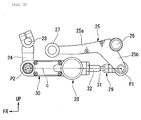
- Fig. 1 is a view showing a left side surface of a transmission 20 adopted in a motorcycle that is one form of a saddle-ride type vehicle.
- the transmission 20 of this embodiment is formed integrally with an engine 10 as a power unit PU.
- a crankcase 12 of the engine 10 configured to rotatably support a crankshaft 11 also serves as a transmission case of the transmission 20.
- a cylinder part 13 of the engine 10 protrudes upwardly toward the front.
- a main shaft 21 of the transmission 20 is disposed on a lower side of a rear portion of the crankshaft 11 in the crankcase 12.
- a countershaft 22 of the transmission 20 is disposed obliquely above a rear portion of the main shaft 21.
- a gear-shift operation shaft 23 configured to operate an unillustrated shift drum of the transmission 20 is disposed below a rear portion of a region where the main shaft 21 is installed in the crankcase 12.
- the gear-shift operation shaft 23 constitutes a gear-shift operation unit of a transmission body.
- One end portion of the gear-shift operation shaft 23 protrudes outwardly from a left end surface of the crankcase 12.
- An input arm 24 is rotatably joined integrally to a left-side protruding portion of the gear-shift operation shaft 23 through serration joining or the like. The input arm 24 extends downwardly in a substantially vertical direction from the gear-shift operation shaft 23.
- a pivot shaft 26 of a shift pedal 25 is rotatably and pivotally supported on a lower end of a left-side rear portion of the crankcase 12.
- the shift pedal 25 has an operation arm piece 25a extending to a front side of the vehicle from the pivot shaft 26, and a connection arm piece 25b extending obliquely downward to a rear side of the vehicle from the pivot shaft 26.
- a pedal shaft 27 (operation unit) protruding outwardly in a vehicle-width direction is supported on an extension end of the operation arm piece 25a.
- the gear-shift-operation transmission device 28 includes an input-side member 29 configured to be rotatably connected to the connection arm piece 25b of the shift pedal 25, and an output-side member 30 configured to be rotatably connected to the input arm 24.
- Fig. 2 is a partial side view of the transmission 20 with the gear-shift-operation transmission device 28 located at the center.
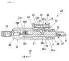
- Figs. 3 to 5 are cross-sectional views of the gear-shift-operation transmission device 28, corresponding to an III-III cross section in Fig. 2 .
- a straight line connecting a connection point P1 between the input-side member 29 and the shift pedal 25 to a connection point P2 between the output-side member 30 and the input arm 24 on the transmission 20 side is called a center axis c of the input-side member 29 and the output-side member 30.
- the input-side member 29 includes an input rod 31 whose rear end portion has the connection point P1 to the shift pedal 25, and an input block 32 coaxially connected to a front portion of the input rod 31.
- the input block 32 is provided with a dent portion 32a in a left-side surface of a front edge portion thereof, and also provided with an upright wall 32b at the front end portion, the upright wall 32b being adjacent to the dent portion 32a.
- a cam groove 33 is formed in a middle portion of the input block 32 in an axial direction.
- the cam groove 33 has a compression-side inclined surface 33a and a tension-side inclined surface 33b.
- the cam groove 33 is a groove dented to have an approximately V shape whose deepest portion serves as a neutral line L1.
- a rear-side surface of the cam groove 33 inclined from the neutral line L1 is the compression-side inclined surface 33a, while a front-side surface of the cam groove 33 inclined from the neutral line L1 is the tension-side inclined surface 33b.
- the cam groove 33 is configured to receive a ball 34, which is an abutting part. The ball 34 will be described later.
- an absolute value of an inclination angle of the compression-side inclined surface 33a to the center axis c is not the same as that of the tension-side inclined surface 33b.
- the absolute value of the inclination angle of the tension-side inclined surface 33b to the center axis c is set to be larger than that of the compression-side inclined surface 33a.
- the output-side member 30 has a cylindrical block 35 having a bottomed cylindrical shape whose front end side is provided with the connection point P2 to the input arm 24, and a lid member 36 configured to close an opening at a rear end side of the cylindrical block 35.
- the cylindrical block 35 houses a portion of the input block 32 of the input-side member 29.
- the input block 32 slidably penetrates the lid member 36.
- a holder unit 37 is attached to a left side surface at the rear edge portion side of the cylindrical block 35.
- the holder unit 37 is configured to hold the aforementioned ball 34 in such a state that the ball 34 is pressed against the cam groove 33.
- a hollow, disc-shaped case 38 houses a disc spring 41, which is a biasing part.
- the disc spring 41 is configured to bias, in a protruding direction, a pressing block 42 slidably held at a bottom portion of the case 38.
- the pressing block 42 has a conically-dented holding groove 42a in a surface at a side facing the inside of the cylindrical block 35, and is capable of holding the ball 34 with the holding groove 42a so that the ball 34 can roll.
- the ball 34 held by the pressing block 42 is pressed against the cam groove 33 by receiving a biasing force of the disc spring 41.
- the cam groove 33 having the compression-side inclined surface 33a and the tension-side inclined surface 33b in opposite directions with respect to the neutral line L1 moves the input-side member 29 and the output-side member 30 relative to each other in the axial direction in cooperation with a biasing force of the disc spring 41 in such a manner that the ball 34 is positioned on the neutral line L1.
- the ball 34 biases the input-side member 29 and the output-side member 30 toward neutral positions.
- the cam groove 33 and pressing members such as the ball 34 and the disc spring 41 constitute reaction-force generating means 40 for exerting a reaction force between the input-side member 29 and the output-side member 30.
- a restriction flange 43 protrudes on an outer circumferential surface of the input block 32. This restriction flange 43 faces restriction walls 35a and 36a of the cylindrical block 35 and the lid member 36 with small gaps thereamong.
- the restriction flange 43 is configured to restrict a relative displacement in the axial direction between the input-side member 29 and the output-side member 30 by abutting against these restriction walls 35a and 36a.
- micro switches 39A and 39B are installed respectively at a position facing a front surface of the upright wall 32b of the input block 32 and at a position face a rear surface of the upright wall 32b.
- the micro switches 39A and 39B are displacement detection sensors configured to detect a relative displacement in the axial direction between the input-side member 29 and the output-side member 30.
- the one micro switch 39A is turned on when the input block 32 is displaced forwardly (compression direction) from a reference position.
- the other micro switch 39B is turned on when the input block 32 is displaced rearwardly (tensile direction) from the reference position.
- these micro switches 39A and 39B are capable of detecting whether the shift pedal 25 is pushed up or down.
- the one micro switch 39A is installed at the center of a bottom wall of the cylindrical block 35 in such a manner that the detector faces the front surface of the upright wall 32b
- the other micro switch 39B is installed at a side wall of the cylindrical block 35 in such a manner that the detector faces the rear surface of the upright wall 32b within the dent portion 32a.
- the motorcycle according to this embodiment includes a mechanism capable of changing the shift stage only by the pushing-up or pushing-down operation on the shift pedal 25 without the driver performing clutch engaging/disengaging operation or accelerator returning operation.
- a controller determines whether the shift pedal 25 is pushed up or down, on the basis of the detection results by the micro switches 39A and 39B of the gear-shift-operation transmission device 28.
- the controller determines that the shift pedal 25 is pushed up or down, the controller reduces a torque of a power transmission system in the transmission 20 by, for example, cutting the engine ignition. While doing so, the controller permits the shift pedal 25 to change the shift stage (change the meshing of gears).
- the transmission 20 includes the gear-shift operation shaft 23, the input arm 24, and the gear-shift-operation transmission device 28, in addition to the transmission body having the gear shift mechanism.
- the holder unit 37 configured to hold the disc spring 41 and the ball 34 is installed outside the left surface of the output-side member 30 in such a manner that the holder unit 37 is directed to the outside of the vehicle, when mounted on the vehicle.
- the gear-shift-operation transmission device 28 is disposed at a position lower than the pedal shaft 27, which is the operation unit of the shift pedal 25, when mounted on the vehicle.
- the cam groove 33 having the compression-side inclined surface 33a and the tension-side inclined surface 33b is provided to the input-side member 29, while the ball 34 configured to roll on the cam groove 33 and the disc spring 41 configured to press and bias the ball 34 are provided to the output-side member 30, and the input-side member 29 and the output-side member 30 are configured to be biased toward the neutral positions by the cooperation of the ball 34 and the disc spring 41 with the cam groove 33.
- the gear-shift-operation transmission device 28 enables reductions in the production cost and in the size of the device as a whole.
- the absolute value of the inclination angle of the compression-side inclined surface 33a of the cam groove 33 to the center axis c is set differently from that of the tension-side inclined surface 33b. This makes it possible to vary a reaction force, depending on whether the input-side member 29 and the output-side member 30 are displaced in the compression direction or in the tensile direction.
- the gear-shift-operation transmission device 28 is capable of making smaller a reaction force, for example, when the driver pushes up the shift pedal 25 (it is harder for the driver to apply an operation load) than when the driver pushes down the shift pedal 25.
- adopting the gear-shift-operation transmission device 28 makes it possible to increase the operability of the transmission 20.
- the disc spring 41 is adopted as the biasing part configured to bias the ball 34 to be pressed against the cam groove 33.
- the biasing part configured to bias the ball 34 which is to be pressed against the cam groove 33 is not limited to the disc spring 41, and it is possible to adopt other elastic members such as a coil spring and an elastic rubber. Nevertheless, adopting the disc spring 41 as the biasing part as in the case of this embodiment can reduce the space occupied in the biasing direction, hence enabling a reduction in the width of the output-side member 30 bulging in a radial direction. Thus, adopting the structure of this embodiment makes it possible to reduce the width of the gear-shift-operation transmission device 28 bulging in a lateral direction of the vehicle, making the vehicle compact.
- the holder unit 37 configured to hold the disc spring 41 is attached to the cylindrical block 35 in such a manner that the holder unit 37 is directed to a lateral side of the vehicle, when mounted on the vehicle; and the entire gear-shift-operation transmission device 28 is disposed at a position lower than the pedal shaft 27, which is the operation unit of the shift pedal 25, when mounted on the vehicle.
- the holder unit 37 hardly interferes with the pedal shaft 27 and a foot of the driver during a gear-shift operation on the shift pedal 25.
- Fig. 6 is a cross-sectional view, similar to that in Fig. 3 , of a gear-shift-operation transmission device 128 according to a second embodiment.
- this gear-shift-operation transmission device 128 is almost the same as that of the first embodiment. Nevertheless, the structure and the arrangement of a micro switch 139B configured to detect a displacement in the tensile direction of the input-side member 29 are different from those in the first embodiment.
- the micro switches 39A and 139B configured to detect displacements in the compression direction and the tensile direction of the input-side member 29 are laterally installed side by side at positions corresponding to a tip end surface of the input block 32 in the cylindrical block 35.
- the one micro switch 39A for detecting the displacement in the compression direction is a switch configured to be turned on when a tip end portion thereof is pressed.
- the other micro switch 139B for detecting the displacement in the tensile direction adopted is a switch configured to be turned on when a tip end portion thereof is stretched.
- the tip end portion of the other micro switch 139B is connected to a tip end portion of the input block 32.
- the gear-shift-operation transmission device 128 according to the second embodiment is advantageous in that the same effects as those in the first embodiment can be obtained, and further that the space occupied by the micro switches 39A and 139B in the axial direction can be reduced.
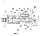
- Fig. 7 is a cross-sectional view, similar to that in Fig. 3 , of a gear-shift-operation transmission device 228 according to a third embodiment.
- the micro switches 39A and 39B are aligned in pair on an inner surface of a left-side portion of the cylindrical block 35 of the output-side member 30. Moreover, at the tip end portion of the input block 32 of the input-side member 29, a detection piece 44 protrudes outwardly in the radial direction. The detection piece 44 is disposed between the detectors of the pair of micro switches 39A and 39B.
- the pair of micro switches 39A and 39B which are the displacement detection sensors, and the holder unit 37 housing the disc spring 41, which is the biasing part, are disposed at the same side (outer side of the vehicle) of the center axis c connecting the connection point P1 at the input-side member 29 side to the connection point P2 at the output-side member 30 side.
- the gear-shift-operation transmission device 228 according to the third embodiment can obtain the same effects as those in the first embodiment, and further makes it possible to simplify the structure at the tip end side of the input block 32.
- adopting the gear-shift-operation transmission device 228 according to this embodiment makes it possible to simplify the structure of the gear-shift-operation transmission device 228 and reduce the cost.
- Fig. 8 is a cross-sectional view, similar to that in Fig. 3 , of a gear-shift-operation transmission device 328 according to a fourth embodiment.
- this gear-shift-operation transmission device 328 is almost the same as that of the first embodiment. Nevertheless, a holder unit 337 attached to the cylindrical block 35 is different from one in the first embodiment.
- the pressing block 42 holding the ball 34 is slidably fitted into a case 338, and a coil spring 45 is disposed inside the case 338.
- the coil spring 45 is a biasing part configured to bias the ball 34 with the pressing block 42.
- the gear-shift-operation transmission device 328 according to the fourth embodiment is advantageous in that the same effects as those in the first embodiment can be obtained, and further that adopting the coil spring 45 as the biasing part configured to bias the ball 34 makes it possible to enhance the setting precision of a biasing
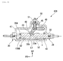
- Fig. 9 is a cross-sectional view, similar to that in Fig. 3 , of a gear-shift-operation transmission device 428 according to a fifth embodiment.
- a front portion side of the input block 32 constituting the input-side member 29 is inserted in a hollow output block 47 constituting the output-side member 30, and a rotatable cam roller 48 is configured to be pressed against the cam groove 33 formed in the side surface of the input block 32.
- the cam roller 48 is rotatably supported by a tip end portion of a swing arm 49 swingably supported in the output block 47.
- the coil spring 45 is configured to bias the swing arm 49 in a direction in which the cam roller 48 is pressed against the cam groove 33.
- the coil spring 45 is supported by a thrust adjustment mechanism 50 attached to the output block 47.
- the biasing force on the cam roller 48 can be adjusted by operating an adjustment nut 51 of the thrust adjustment mechanism 50 from the outside of the output block 47. Further, the same pair of micro switches 39A and 139B as those in the second embodiment are attached to positions facing the tip end surface of the input block 32 in the output block 47.
- reference numeral 52 in Fig. 9 denotes a support roller rotatably supported by the input block 32 and configured to abut against an inner surface of the output block 47 to receive a pressing force inputted from the cam roller 48 to the input block 32.
- the gear-shift-operation transmission device 428 according to the fifth embodiment is advantageous in that almost the same basic effects as those in the fourth embodiment can be obtained, and further that it is possible to further enhance the setting precision of a reaction force because the cam roller 48 supported by the swing arm 49 is stably pressed against the cam groove 33, and also because the thrust adjustment mechanism 50 is capable of fine adjustment of the biasing force of the coil spring 45.
- the cam groove 33 is provided on the input-side member 29 side, while the pressing member to be elastically pressed against the cam groove 33 is provided on the output-side member 30 side.
- the cam groove may be provided on the output-side member side, while the pressing member may be provided on the input-side member side.
- the displacement detection sensors configured to detect a relative displacement between the input-side member 29 and the output-side member 30 are constituted of the micro switches 39A and 39B (139B). Nevertheless, the displacement detection sensors are not limited thereto, and may be constituted of, for example, a proximity sensor or the like.
- the vehicle to which this invention is applied is not limited to motorcycles (including motorized bicycles and scooter-type vehicles), and also includes small vehicles with three wheels (including a vehicle with one front wheel and two rear wheels and a vehicle with two front wheels and one rear wheel) or four wheels.
Applications Claiming Priority (1)
| Application Number | Priority Date | Filing Date | Title |
|---|---|---|---|
| JP2014188136A JP6043765B2 (ja) | 2014-09-16 | 2014-09-16 | 鞍乗り型車両の変速操作伝達装置及び変速機 |
Publications (2)
| Publication Number | Publication Date |
|---|---|
| EP2998616A1 true EP2998616A1 (fr) | 2016-03-23 |
| EP2998616B1 EP2998616B1 (fr) | 2020-11-25 |
Family
ID=54238181
Family Applications (1)
| Application Number | Title | Priority Date | Filing Date |
|---|---|---|---|
| EP15185053.4A Active EP2998616B1 (fr) | 2014-09-16 | 2015-09-14 | Dispositif de transmission à changement de vitesse et transmission pour véhicule de type à selle |
Country Status (2)
| Country | Link |
|---|---|
| EP (1) | EP2998616B1 (fr) |
| JP (1) | JP6043765B2 (fr) |
Cited By (1)
| Publication number | Priority date | Publication date | Assignee | Title |
|---|---|---|---|---|
| EP4053433A1 (fr) * | 2021-03-01 | 2022-09-07 | Suzuki Motor Corporation | Dispositif de changement de vitesse |
Families Citing this family (3)
| Publication number | Priority date | Publication date | Assignee | Title |
|---|---|---|---|---|
| JP6897212B2 (ja) * | 2017-03-24 | 2021-06-30 | スズキ株式会社 | エンジンの排気浄化装置及び車両 |
| WO2019020425A1 (fr) * | 2017-07-28 | 2019-01-31 | Bing Power Systems Gmbh | Émetteur de signaux de changement de vitesse pour boîte de vitesses d'un véhicule et dispositif de changement de vitesse pour boîte de vitesses |
| JP7105270B2 (ja) * | 2020-03-31 | 2022-07-22 | 本田技研工業株式会社 | 鞍乗り型車両における変速検知装置 |
Citations (4)
| Publication number | Priority date | Publication date | Assignee | Title |
|---|---|---|---|---|
| EP2107278A1 (fr) * | 2008-04-03 | 2009-10-07 | Honda Motor Co., Ltd. | Système de changement de vitesse et moto |
| DE102010015037A1 (de) | 2010-04-15 | 2011-10-20 | Bayerische Motoren Werke Aktiengesellschaft | Schalteinrichtung für Motorräder |
| DE102011052494B3 (de) * | 2011-08-08 | 2012-10-31 | Hs Products Engineering Gmbh | Kraftübertragungsvorrichtung für ein Getriebe mit einem Schaltassistenzsystem |
| DE102012209963A1 (de) * | 2012-06-14 | 2013-12-19 | Robert Bosch Gmbh | Motorradschaltung mit Schaltassistent zum Schalten ohne Kupplungsbetätigung und Verfahren hierzu |
-
2014
- 2014-09-16 JP JP2014188136A patent/JP6043765B2/ja active Active
-
2015
- 2015-09-14 EP EP15185053.4A patent/EP2998616B1/fr active Active
Patent Citations (4)
| Publication number | Priority date | Publication date | Assignee | Title |
|---|---|---|---|---|
| EP2107278A1 (fr) * | 2008-04-03 | 2009-10-07 | Honda Motor Co., Ltd. | Système de changement de vitesse et moto |
| DE102010015037A1 (de) | 2010-04-15 | 2011-10-20 | Bayerische Motoren Werke Aktiengesellschaft | Schalteinrichtung für Motorräder |
| DE102011052494B3 (de) * | 2011-08-08 | 2012-10-31 | Hs Products Engineering Gmbh | Kraftübertragungsvorrichtung für ein Getriebe mit einem Schaltassistenzsystem |
| DE102012209963A1 (de) * | 2012-06-14 | 2013-12-19 | Robert Bosch Gmbh | Motorradschaltung mit Schaltassistent zum Schalten ohne Kupplungsbetätigung und Verfahren hierzu |
Cited By (2)
| Publication number | Priority date | Publication date | Assignee | Title |
|---|---|---|---|---|
| EP4053433A1 (fr) * | 2021-03-01 | 2022-09-07 | Suzuki Motor Corporation | Dispositif de changement de vitesse |
| US11692620B2 (en) | 2021-03-01 | 2023-07-04 | Suzuki Motor Corporation | Shift device |
Also Published As
| Publication number | Publication date |
|---|---|
| JP2016061339A (ja) | 2016-04-25 |
| EP2998616B1 (fr) | 2020-11-25 |
| JP6043765B2 (ja) | 2016-12-14 |
Similar Documents
| Publication | Publication Date | Title |
|---|---|---|
| EP2998616B1 (fr) | Dispositif de transmission à changement de vitesse et transmission pour véhicule de type à selle | |
| US8365856B2 (en) | Shifting system for a motorcycle, and motorcycle incorporating same | |
| EP2263923B1 (fr) | Structure d'installation d'un capteur de temps à pédale | |
| JP4856405B2 (ja) | 変速装置、自動二輪車、及び車両 | |
| US9057436B1 (en) | Shift device for transmission | |
| EP2266849A2 (fr) | Dispositif à pédales pour véhicule à moteur | |
| EP3196511B1 (fr) | Dispositif de changement de vitesse pour motocyclette | |
| US10875602B2 (en) | Transmission shifting assistance device and shifting device for a motorcycle | |
| EP2942247A1 (fr) | Système de frein et véhicule | |
| US10975956B2 (en) | Force transmission device for a transmission | |
| CN108027626B (zh) | 具有致动阻尼的踏板装置 | |
| US10012312B2 (en) | Speed change apparatus for vehicle | |
| EP3366939A1 (fr) | Motocyclette | |
| CN108025720B (zh) | 鞍乘型车辆 | |
| JP6238237B2 (ja) | 鞍乗り型車両の変速操作伝達装置及び変速機 | |
| JP5153710B2 (ja) | 鞍乗り型車両の連動ブレーキ装置 | |
| JP6678942B2 (ja) | クラッチを係合させた状態で変速を行うように自動二輪車の手動変速機を作動する変速装置 | |
| US11015703B2 (en) | Gear-changing apparatus for actuating a manual gearbox of a motorcycle for carrying out a gear change with the clutch engaged | |
| JP6173285B2 (ja) | 鞍乗り型車両の変速操作伝達装置及び変速機 | |
| EP3604057B1 (fr) | Système de freinage de véhicule et véhicule comprenant ce système de freinage | |
| US9175769B1 (en) | Speed change apparatus of vehicle | |
| JP2021162066A (ja) | 鞍乗り型車両における変速検知装置 | |
| JP6222149B2 (ja) | マスタシリンダの操作機構 | |
| KR20060067660A (ko) | 스티어링 컬럼 구조 | |
| JP2015132346A (ja) | 鞍乗型車両 |
Legal Events
| Date | Code | Title | Description |
|---|---|---|---|
| PUAI | Public reference made under article 153(3) epc to a published international application that has entered the european phase |
Free format text: ORIGINAL CODE: 0009012 |
|
| 17P | Request for examination filed |
Effective date: 20150914 |
|
| AK | Designated contracting states |
Kind code of ref document: A1 Designated state(s): AL AT BE BG CH CY CZ DE DK EE ES FI FR GB GR HR HU IE IS IT LI LT LU LV MC MK MT NL NO PL PT RO RS SE SI SK SM TR |
|
| AX | Request for extension of the european patent |
Extension state: BA ME |
|
| RIN1 | Information on inventor provided before grant (corrected) |
Inventor name: YAMASHITA, AKIHIRO Inventor name: ONO, JUNYA Inventor name: ADACHI, JUN Inventor name: SHIOMI, YOSHINOBU |
|
| RIC1 | Information provided on ipc code assigned before grant |
Ipc: F16H 63/50 20060101ALI20200213BHEP Ipc: F16H 59/02 20060101AFI20200213BHEP Ipc: F16H 61/26 20060101ALI20200213BHEP |
|
| GRAP | Despatch of communication of intention to grant a patent |
Free format text: ORIGINAL CODE: EPIDOSNIGR1 |
|
| STAA | Information on the status of an ep patent application or granted ep patent |
Free format text: STATUS: GRANT OF PATENT IS INTENDED |
|
| INTG | Intention to grant announced |
Effective date: 20200612 |
|
| GRAS | Grant fee paid |
Free format text: ORIGINAL CODE: EPIDOSNIGR3 |
|
| GRAA | (expected) grant |
Free format text: ORIGINAL CODE: 0009210 |
|
| STAA | Information on the status of an ep patent application or granted ep patent |
Free format text: STATUS: THE PATENT HAS BEEN GRANTED |
|
| AK | Designated contracting states |
Kind code of ref document: B1 Designated state(s): AL AT BE BG CH CY CZ DE DK EE ES FI FR GB GR HR HU IE IS IT LI LT LU LV MC MK MT NL NO PL PT RO RS SE SI SK SM TR |
|
| REG | Reference to a national code |
Ref country code: GB Ref legal event code: FG4D |
|
| REG | Reference to a national code |
Ref country code: CH Ref legal event code: EP |
|
| REG | Reference to a national code |
Ref country code: AT Ref legal event code: REF Ref document number: 1338711 Country of ref document: AT Kind code of ref document: T Effective date: 20201215 |
|
| REG | Reference to a national code |
Ref country code: DE Ref legal event code: R096 Ref document number: 602015062438 Country of ref document: DE |
|
| REG | Reference to a national code |
Ref country code: IE Ref legal event code: FG4D |
|
| REG | Reference to a national code |
Ref country code: AT Ref legal event code: MK05 Ref document number: 1338711 Country of ref document: AT Kind code of ref document: T Effective date: 20201125 |
|
| REG | Reference to a national code |
Ref country code: NL Ref legal event code: MP Effective date: 20201125 |
|
| PG25 | Lapsed in a contracting state [announced via postgrant information from national office to epo] |
Ref country code: FI Free format text: LAPSE BECAUSE OF FAILURE TO SUBMIT A TRANSLATION OF THE DESCRIPTION OR TO PAY THE FEE WITHIN THE PRESCRIBED TIME-LIMIT Effective date: 20201125 Ref country code: RS Free format text: LAPSE BECAUSE OF FAILURE TO SUBMIT A TRANSLATION OF THE DESCRIPTION OR TO PAY THE FEE WITHIN THE PRESCRIBED TIME-LIMIT Effective date: 20201125 Ref country code: PT Free format text: LAPSE BECAUSE OF FAILURE TO SUBMIT A TRANSLATION OF THE DESCRIPTION OR TO PAY THE FEE WITHIN THE PRESCRIBED TIME-LIMIT Effective date: 20210325 Ref country code: NO Free format text: LAPSE BECAUSE OF FAILURE TO SUBMIT A TRANSLATION OF THE DESCRIPTION OR TO PAY THE FEE WITHIN THE PRESCRIBED TIME-LIMIT Effective date: 20210225 Ref country code: GR Free format text: LAPSE BECAUSE OF FAILURE TO SUBMIT A TRANSLATION OF THE DESCRIPTION OR TO PAY THE FEE WITHIN THE PRESCRIBED TIME-LIMIT Effective date: 20210226 |
|
| PG25 | Lapsed in a contracting state [announced via postgrant information from national office to epo] |
Ref country code: LV Free format text: LAPSE BECAUSE OF FAILURE TO SUBMIT A TRANSLATION OF THE DESCRIPTION OR TO PAY THE FEE WITHIN THE PRESCRIBED TIME-LIMIT Effective date: 20201125 Ref country code: PL Free format text: LAPSE BECAUSE OF FAILURE TO SUBMIT A TRANSLATION OF THE DESCRIPTION OR TO PAY THE FEE WITHIN THE PRESCRIBED TIME-LIMIT Effective date: 20201125 Ref country code: SE Free format text: LAPSE BECAUSE OF FAILURE TO SUBMIT A TRANSLATION OF THE DESCRIPTION OR TO PAY THE FEE WITHIN THE PRESCRIBED TIME-LIMIT Effective date: 20201125 Ref country code: IS Free format text: LAPSE BECAUSE OF FAILURE TO SUBMIT A TRANSLATION OF THE DESCRIPTION OR TO PAY THE FEE WITHIN THE PRESCRIBED TIME-LIMIT Effective date: 20210325 Ref country code: AT Free format text: LAPSE BECAUSE OF FAILURE TO SUBMIT A TRANSLATION OF THE DESCRIPTION OR TO PAY THE FEE WITHIN THE PRESCRIBED TIME-LIMIT Effective date: 20201125 Ref country code: BG Free format text: LAPSE BECAUSE OF FAILURE TO SUBMIT A TRANSLATION OF THE DESCRIPTION OR TO PAY THE FEE WITHIN THE PRESCRIBED TIME-LIMIT Effective date: 20210225 |
|
| REG | Reference to a national code |
Ref country code: LT Ref legal event code: MG9D |
|
| PG25 | Lapsed in a contracting state [announced via postgrant information from national office to epo] |
Ref country code: HR Free format text: LAPSE BECAUSE OF FAILURE TO SUBMIT A TRANSLATION OF THE DESCRIPTION OR TO PAY THE FEE WITHIN THE PRESCRIBED TIME-LIMIT Effective date: 20201125 |
|
| PG25 | Lapsed in a contracting state [announced via postgrant information from national office to epo] |
Ref country code: RO Free format text: LAPSE BECAUSE OF FAILURE TO SUBMIT A TRANSLATION OF THE DESCRIPTION OR TO PAY THE FEE WITHIN THE PRESCRIBED TIME-LIMIT Effective date: 20201125 Ref country code: SK Free format text: LAPSE BECAUSE OF FAILURE TO SUBMIT A TRANSLATION OF THE DESCRIPTION OR TO PAY THE FEE WITHIN THE PRESCRIBED TIME-LIMIT Effective date: 20201125 Ref country code: LT Free format text: LAPSE BECAUSE OF FAILURE TO SUBMIT A TRANSLATION OF THE DESCRIPTION OR TO PAY THE FEE WITHIN THE PRESCRIBED TIME-LIMIT Effective date: 20201125 Ref country code: SM Free format text: LAPSE BECAUSE OF FAILURE TO SUBMIT A TRANSLATION OF THE DESCRIPTION OR TO PAY THE FEE WITHIN THE PRESCRIBED TIME-LIMIT Effective date: 20201125 Ref country code: CZ Free format text: LAPSE BECAUSE OF FAILURE TO SUBMIT A TRANSLATION OF THE DESCRIPTION OR TO PAY THE FEE WITHIN THE PRESCRIBED TIME-LIMIT Effective date: 20201125 Ref country code: EE Free format text: LAPSE BECAUSE OF FAILURE TO SUBMIT A TRANSLATION OF THE DESCRIPTION OR TO PAY THE FEE WITHIN THE PRESCRIBED TIME-LIMIT Effective date: 20201125 |
|
| REG | Reference to a national code |
Ref country code: DE Ref legal event code: R097 Ref document number: 602015062438 Country of ref document: DE |
|
| REG | Reference to a national code |
Ref country code: DE Ref legal event code: R084 Ref document number: 602015062438 Country of ref document: DE |
|
| PG25 | Lapsed in a contracting state [announced via postgrant information from national office to epo] |
Ref country code: DK Free format text: LAPSE BECAUSE OF FAILURE TO SUBMIT A TRANSLATION OF THE DESCRIPTION OR TO PAY THE FEE WITHIN THE PRESCRIBED TIME-LIMIT Effective date: 20201125 |
|
| PLBE | No opposition filed within time limit |
Free format text: ORIGINAL CODE: 0009261 |
|
| STAA | Information on the status of an ep patent application or granted ep patent |
Free format text: STATUS: NO OPPOSITION FILED WITHIN TIME LIMIT |
|
| PG25 | Lapsed in a contracting state [announced via postgrant information from national office to epo] |
Ref country code: NL Free format text: LAPSE BECAUSE OF FAILURE TO SUBMIT A TRANSLATION OF THE DESCRIPTION OR TO PAY THE FEE WITHIN THE PRESCRIBED TIME-LIMIT Effective date: 20201125 Ref country code: AL Free format text: LAPSE BECAUSE OF FAILURE TO SUBMIT A TRANSLATION OF THE DESCRIPTION OR TO PAY THE FEE WITHIN THE PRESCRIBED TIME-LIMIT Effective date: 20201125 |
|
| PGFP | Annual fee paid to national office [announced via postgrant information from national office to epo] |
Ref country code: FR Payment date: 20210927 Year of fee payment: 7 Ref country code: IT Payment date: 20210930 Year of fee payment: 7 |
|
| 26N | No opposition filed |
Effective date: 20210826 |
|
| PG25 | Lapsed in a contracting state [announced via postgrant information from national office to epo] |
Ref country code: ES Free format text: LAPSE BECAUSE OF FAILURE TO SUBMIT A TRANSLATION OF THE DESCRIPTION OR TO PAY THE FEE WITHIN THE PRESCRIBED TIME-LIMIT Effective date: 20201125 Ref country code: SI Free format text: LAPSE BECAUSE OF FAILURE TO SUBMIT A TRANSLATION OF THE DESCRIPTION OR TO PAY THE FEE WITHIN THE PRESCRIBED TIME-LIMIT Effective date: 20201125 |
|
| REG | Reference to a national code |
Ref country code: CH Ref legal event code: PL |
|
| REG | Reference to a national code |
Ref country code: BE Ref legal event code: MM Effective date: 20210930 |
|
| GBPC | Gb: european patent ceased through non-payment of renewal fee |
Effective date: 20210914 |
|
| PG25 | Lapsed in a contracting state [announced via postgrant information from national office to epo] |
Ref country code: IS Free format text: LAPSE BECAUSE OF FAILURE TO SUBMIT A TRANSLATION OF THE DESCRIPTION OR TO PAY THE FEE WITHIN THE PRESCRIBED TIME-LIMIT Effective date: 20210325 Ref country code: MC Free format text: LAPSE BECAUSE OF FAILURE TO SUBMIT A TRANSLATION OF THE DESCRIPTION OR TO PAY THE FEE WITHIN THE PRESCRIBED TIME-LIMIT Effective date: 20201125 |
|
| PG25 | Lapsed in a contracting state [announced via postgrant information from national office to epo] |
Ref country code: LU Free format text: LAPSE BECAUSE OF NON-PAYMENT OF DUE FEES Effective date: 20210914 Ref country code: IE Free format text: LAPSE BECAUSE OF NON-PAYMENT OF DUE FEES Effective date: 20210914 Ref country code: GB Free format text: LAPSE BECAUSE OF NON-PAYMENT OF DUE FEES Effective date: 20210914 Ref country code: BE Free format text: LAPSE BECAUSE OF NON-PAYMENT OF DUE FEES Effective date: 20210930 |
|
| PG25 | Lapsed in a contracting state [announced via postgrant information from national office to epo] |
Ref country code: LI Free format text: LAPSE BECAUSE OF NON-PAYMENT OF DUE FEES Effective date: 20210930 Ref country code: CH Free format text: LAPSE BECAUSE OF NON-PAYMENT OF DUE FEES Effective date: 20210930 |
|
| PG25 | Lapsed in a contracting state [announced via postgrant information from national office to epo] |
Ref country code: HU Free format text: LAPSE BECAUSE OF FAILURE TO SUBMIT A TRANSLATION OF THE DESCRIPTION OR TO PAY THE FEE WITHIN THE PRESCRIBED TIME-LIMIT; INVALID AB INITIO Effective date: 20150914 |
|
| PG25 | Lapsed in a contracting state [announced via postgrant information from national office to epo] |
Ref country code: CY Free format text: LAPSE BECAUSE OF FAILURE TO SUBMIT A TRANSLATION OF THE DESCRIPTION OR TO PAY THE FEE WITHIN THE PRESCRIBED TIME-LIMIT Effective date: 20201125 |
|
| PG25 | Lapsed in a contracting state [announced via postgrant information from national office to epo] |
Ref country code: FR Free format text: LAPSE BECAUSE OF NON-PAYMENT OF DUE FEES Effective date: 20220930 |
|
| PG25 | Lapsed in a contracting state [announced via postgrant information from national office to epo] |
Ref country code: IT Free format text: LAPSE BECAUSE OF NON-PAYMENT OF DUE FEES Effective date: 20220914 |
|
| PGFP | Annual fee paid to national office [announced via postgrant information from national office to epo] |
Ref country code: DE Payment date: 20230718 Year of fee payment: 9 |