EP2998611B1 - Schwingungsisolator mit pneumatischer Feder - Google Patents
Schwingungsisolator mit pneumatischer Feder Download PDFInfo
- Publication number
- EP2998611B1 EP2998611B1 EP14185342.4A EP14185342A EP2998611B1 EP 2998611 B1 EP2998611 B1 EP 2998611B1 EP 14185342 A EP14185342 A EP 14185342A EP 2998611 B1 EP2998611 B1 EP 2998611B1
- Authority
- EP
- European Patent Office
- Prior art keywords
- vibration isolator
- vibration
- leaf spring
- piston
- spring
- Prior art date
- Legal status (The legal status is an assumption and is not a legal conclusion. Google has not performed a legal analysis and makes no representation as to the accuracy of the status listed.)
- Active
Links
- 238000002955 isolation Methods 0.000 claims description 26
- 238000005452 bending Methods 0.000 claims description 25
- 239000012530 fluid Substances 0.000 claims description 8
- 125000006850 spacer group Chemical group 0.000 claims description 7
- 239000012212 insulator Substances 0.000 description 5
- 239000012528 membrane Substances 0.000 description 5
- 230000006978 adaptation Effects 0.000 description 2
- 238000011161 development Methods 0.000 description 2
- 230000018109 developmental process Effects 0.000 description 2
- 238000001459 lithography Methods 0.000 description 2
- 239000004065 semiconductor Substances 0.000 description 2
- 230000001419 dependent effect Effects 0.000 description 1
- 238000010586 diagram Methods 0.000 description 1
- 230000000694 effects Effects 0.000 description 1
- 230000002349 favourable effect Effects 0.000 description 1
- 238000007689 inspection Methods 0.000 description 1
- 230000003287 optical effect Effects 0.000 description 1
- 230000000284 resting effect Effects 0.000 description 1
- 230000003313 weakening effect Effects 0.000 description 1
Images


Classifications
-
- F—MECHANICAL ENGINEERING; LIGHTING; HEATING; WEAPONS; BLASTING
- F16—ENGINEERING ELEMENTS AND UNITS; GENERAL MEASURES FOR PRODUCING AND MAINTAINING EFFECTIVE FUNCTIONING OF MACHINES OR INSTALLATIONS; THERMAL INSULATION IN GENERAL
- F16F—SPRINGS; SHOCK-ABSORBERS; MEANS FOR DAMPING VIBRATION
- F16F15/00—Suppression of vibrations in systems; Means or arrangements for avoiding or reducing out-of-balance forces, e.g. due to motion
- F16F15/02—Suppression of vibrations of non-rotating, e.g. reciprocating systems; Suppression of vibrations of rotating systems by use of members not moving with the rotating systems
- F16F15/023—Suppression of vibrations of non-rotating, e.g. reciprocating systems; Suppression of vibrations of rotating systems by use of members not moving with the rotating systems using fluid means
- F16F15/0232—Suppression of vibrations of non-rotating, e.g. reciprocating systems; Suppression of vibrations of rotating systems by use of members not moving with the rotating systems using fluid means with at least one gas spring
-
- F—MECHANICAL ENGINEERING; LIGHTING; HEATING; WEAPONS; BLASTING
- F16—ENGINEERING ELEMENTS AND UNITS; GENERAL MEASURES FOR PRODUCING AND MAINTAINING EFFECTIVE FUNCTIONING OF MACHINES OR INSTALLATIONS; THERMAL INSULATION IN GENERAL
- F16F—SPRINGS; SHOCK-ABSORBERS; MEANS FOR DAMPING VIBRATION
- F16F13/00—Units comprising springs of the non-fluid type as well as vibration-dampers, shock-absorbers, or fluid springs
- F16F13/002—Units comprising springs of the non-fluid type as well as vibration-dampers, shock-absorbers, or fluid springs comprising at least one fluid spring
-
- F—MECHANICAL ENGINEERING; LIGHTING; HEATING; WEAPONS; BLASTING
- F16—ENGINEERING ELEMENTS AND UNITS; GENERAL MEASURES FOR PRODUCING AND MAINTAINING EFFECTIVE FUNCTIONING OF MACHINES OR INSTALLATIONS; THERMAL INSULATION IN GENERAL
- F16F—SPRINGS; SHOCK-ABSORBERS; MEANS FOR DAMPING VIBRATION
- F16F15/00—Suppression of vibrations in systems; Means or arrangements for avoiding or reducing out-of-balance forces, e.g. due to motion
- F16F15/02—Suppression of vibrations of non-rotating, e.g. reciprocating systems; Suppression of vibrations of rotating systems by use of members not moving with the rotating systems
- F16F15/023—Suppression of vibrations of non-rotating, e.g. reciprocating systems; Suppression of vibrations of rotating systems by use of members not moving with the rotating systems using fluid means
- F16F15/027—Suppression of vibrations of non-rotating, e.g. reciprocating systems; Suppression of vibrations of rotating systems by use of members not moving with the rotating systems using fluid means comprising control arrangements
- F16F15/0275—Control of stiffness
-
- F—MECHANICAL ENGINEERING; LIGHTING; HEATING; WEAPONS; BLASTING
- F16—ENGINEERING ELEMENTS AND UNITS; GENERAL MEASURES FOR PRODUCING AND MAINTAINING EFFECTIVE FUNCTIONING OF MACHINES OR INSTALLATIONS; THERMAL INSULATION IN GENERAL
- F16F—SPRINGS; SHOCK-ABSORBERS; MEANS FOR DAMPING VIBRATION
- F16F15/00—Suppression of vibrations in systems; Means or arrangements for avoiding or reducing out-of-balance forces, e.g. due to motion
- F16F15/02—Suppression of vibrations of non-rotating, e.g. reciprocating systems; Suppression of vibrations of rotating systems by use of members not moving with the rotating systems
- F16F15/04—Suppression of vibrations of non-rotating, e.g. reciprocating systems; Suppression of vibrations of rotating systems by use of members not moving with the rotating systems using elastic means
- F16F15/046—Suppression of vibrations of non-rotating, e.g. reciprocating systems; Suppression of vibrations of rotating systems by use of members not moving with the rotating systems using elastic means using combinations of springs of different kinds
Definitions
- the invention relates to a vibration isolator with a pneumatic spring.
- the invention relates to a vibration isolator used in a stationary vibration isolation system for storage of devices of the semiconductor industry, that is, for example, of lithography devices, optical inspection devices, and wafer handling devices.
- vibration isolation systems are known.
- the patent shows DE 698 177 50 T2 a vibration isolation system, which is used for the vibration-isolated storage of a lithographic device.
- US6926263B1 Further embodiments of such devices are shown.
- Pneumatic springs can be controlled via a servo valve and integrated into the control loop of an active vibration isolation system.
- An insulating mass is stored on three or more vibration isolators.
- isolators with a pneumatic spring is a vibration isolation of Surface already reached above the natural frequency of the spring mass system.
- non-contact actuators such as magnetic actuators, with which an active vibration isolation is possible. These contribute in particular to a vibration isolation in the higher-frequency range.
- the invention is based on the object to reduce the aforementioned disadvantages of a pneumatic vibration isolator.
- a simply constructed vibration isolator in which a leveling is possible via a pneumatic spring and in which at the same time a relatively high natural frequency, in particular a natural frequency of more than 5 Hz, can be achieved both in the horizontal and in the vertical direction.
- the invention relates to a vibration isolator, which is intended in particular for use in a stationary arranged vibration isolation system. This serves in particular for the vibration-isolated storage of devices of the semiconductor industry.
- the vibration isolator includes a pneumatic spring.
- This usually includes a supported in a working space by fluid pressure piston.
- the invention relates to a pneumatic spring in the form of a closed system, in which the working space is formed by means of a membrane.
- the pneumatic spring is connected via a bending rod or an articulated pendulum with a headboard.
- the piston of the spring is connected to an upper part of the insulator. It is also conceivable to turn the arrangement over.
- the bending rod or articulated pendulum essentially determines the horizontal rigidity of the system, ie the stiffness in the horizontal direction when installed.
- this can be a bending bar with a diameter that does not change, which bends sideways when loaded horizontally.
- the bending rod or articulated pendulum is in turn coupled via at least one effective in a vertical direction leaf spring to the base part.
- the stiffness of the insulator is determined in the vertical direction.
- leaf spring and articulated pendulum allows a particularly simple adaptation of the insulator, such as by exchange of bending rod or leaf spring.
- the horizontal rigidity can be adjusted independently of the vertical rigidity.
- leaf springs also has the advantage that leaf springs can be manufactured precisely and the calculated stiffness correlates to a large extent with the actual stiffness.
- the pneumatic spring comprises a piston with an extension.
- the bending rod or the articulated pendulum is arranged at least in sections in the extension.
- the extension is formed in particular as a central recess of the piston, which projects into the working space of the piston.
- the working space of the piston now serves to accommodate the bending rod or the articulated pendulum. This has a favorable effect on the natural frequency, reduces the prolongation of vibrations and ensures a more compact design.
- the extension protrudes into the work space by at least half the height of the working space.
- the leaf spring is part of a leaf spring package.
- the leaf springs are preferably spaced apart by spacers.
- a leaf spring As a leaf spring, a leaf spring is used in a preferred embodiment, in particular for the leaf spring package, which comprises a plurality of spring segments connected in parallel.
- leaf spring which comprises an outer part and an inner part, which are connected via a plurality, preferably at least three, arms, which form the actual leaf springs.
- the leaf spring may in particular have an inner ring connected to the piston or the extension of the piston and an outer ring which is connected to the base part.
- inner ring and / or outer ring can not be circular segment-shaped, but also polygonal.
- a vibration isolator can be provided, which has a natural frequency of more than 5 hertz in the installed state in the vertical and / or horizontal direction.
- leaf spring package accessible from one direction, in which the individual leaf springs are removed and can be replaced with other springs or spacers.
- the invention particularly relates to a vibration isolator which is used in connection with a vibration isolation system having an active control.
- At least one sensor is provided which detects vibrations or the position of the load to be insulated or the ground on which the vibration isolation system rests.
- the fluid pressure in the pneumatic spring of the vibration isolator is controlled via a servo valve and a controller connected to the at least one sensor.
- level compensation can be provided via the vibration isolator by detecting the vertical position of the load to be isolated and controlling the fluid pressure in the pneumatic spring based on a comparison of the actual position with a desired position.
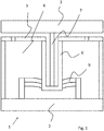
- a vibration isolator 1 can be seen in a sectional view.
- This comprises a base part 2 and a head part 3, which is mounted vibration-isolated from the base part 2.
- the head part 3 may be part of an assembly that forms the vibration isolator 1, which is then incorporated into a vibration isolation system.
- the head part 3 can be fastened, for example, to a table which serves for the vibration-isolated mounting of a lithography device.
- the headboard 3 is an integral part of the table.
- the vibration isolator 1 further comprises a working space 4 in which a fluid pressure is present and over which a piston 5 is supported.
- the working space 4 is closed by means of a membrane (not shown), which makes the piston 5 movable relative to the rest of the housing of the vibration isolator.
- the piston 5 comprises a vertically extending extension 6.
- the extension 6 is screwed in this embodiment with the rest of the piston.
- a one-piece design is also conceivable.
- a bending rod 7 is fixed, which is connected to the head part 3.
- the piston 5, in this embodiment, the extension 6 of the piston 5 is connected via a leaf spring package 9 with the base part 2.
- the rigidity of the insulator is predominantly determined by the leaf spring assembly 9, while the pneumatic spring, which is formed by the working space 4 and the piston 5, primarily serves to level balance.
- Fig. 2 shows a sectional view of an embodiment of a vibration isolator.
- This comprises the base part 2 as well as the vibration-insulated head part 3 coupled thereto.
- the working space 4 is closed by means of a membrane 8 arranged below the head part 3.
- the membrane 8 is connected by means of a clamping ring 13 with the housing 14 of the working space 4.
- the bending rod 7 is connected at the bottom by means of the screw 15 with the extension 6.
- the extension 6 comprises a lower part 20.
- the bending rod can be removed and replaced to vote for the insulator.
- the screw 15 is accessible after removing the screw 17, which closes the working space 4.
- the housing 14 of the working space 4 is connected to the base part 2 by means of the screws 16.
- the at least one fluid line via which the working space 4 is supplied with fluid.
- Fig. 3 shows a detailed view of a portion of a vibration isolator according to the invention, namely the extension 6, which is connected to the leaf spring package 9.
- leaf spring assembly 9 is connected by screws 18 to the base part 2 and screws 19 with the extension 6.
- the leaf spring package 9 can be removed consisting of leaf springs and spacers.
- lower leaf spring packet 21 Spaced apart from the leaf spring package 9 is a lower leaf spring packet 21.
- the lower leaf spring packet 21 and the lower part are held by screws, which are not visible in this sectional view.
- Fig. 4 shows a perspective partially broken view of an assembly with a vibration isolator according to the invention.
- Fig. 5 shows a view of an exemplary leaf spring 10.
- the leaf spring shown in this embodiment comprises an inner ring 26, which has holes 27 to the extension of the piston (6 in Fig. 3 ) to be attached.
- An outer ring 23 includes holes 24 for attachment to the base.
- a spring action in the vertical direction in this embodiment three spring segments 25 sure which outer ring 23 and inner ring 26 connect to each other and which are connected in parallel.
- Fig. 6 shows a schematic view of a vibration isolation system 30th
- This comprises a table 31, which is mounted on at least three vibration isolators 1.
- control device 28 Based on the signal from the sensors 29, the control device 28 controls the pressure in the vibration isolators 1 and thus provides a level compensation.
- the vibration isolation system can also comprise further sensors and / or actuators, in particular non-contact force actuators.
- the vibration isolators 1 can be set at the respective position in a very simple manner to a same natural frequency.
Description
- Die Erfindung betrifft einen Schwingungsisolator mit einer pneumatischen Feder. Insbesondere betrifft die Erfindung einen Schwingungsisolator, der in einem stationären Schwingungsisolationssystem zur Lagerung von Geräten der Halbleiterindustrie verwendet wird, also beispielsweise von Lithographiegeräten, optischen Inspektionsgeräten und Waver-Handling-Einrichtungen.
- Derartige Schwingungsisolationssysteme sind bekannt. So zeigt beispielsweise die Patentschrift
DE 698 177 50 T2 ein Schwingungsisolationssystem, welches zur schwingungsisolierten Lagerung eines Lithographiegeräts verwendet wird. In der DruckschriftUS6926263B1 sind weitere Ausführungsformen von solchen Vorrichtungen gezeigt. - Pneumatische Federn können dabei über ein Servoventil angesteuert werden und in die Regelschleife eines aktiven Schwingungsisolationssystems integriert werden.
- Eine zu isolierende Masse ist dabei auf drei oder mehr Schwingungsisolatoren gelagert. Durch Isolatoren mit einer pneumatischen Feder wird eine Schwingungsisolation vom Untergrund bereits oberhalb der Eigenfrequenz des Federmassesystems erreicht.
- Neben einer aktiven Schwingungsisolation über die pneumatischen Federn selbst gibt es auch berührungslos arbeitende Aktoren, wie beispielsweise Magnetaktoren, mit denen eine aktive Schwingungsisolation möglich ist. Diese tragen insbesondere zu einer Schwingungsisolation im höherfrequenten Bereich bei.
- Weiter dienen pneumatische Federn dann einer Niveauregulierung des Systems. Eine Änderung des auf dem Schwingungsisolationssystem ruhenden Gewichts führt daher zu einer Änderung des nötigen Luftdrucks, was nur in Grenzen möglich ist und was in vielen Fällen zu einer unverwünschten Änderung der Eigenfrequenz führt.
- Problematisch ist es, bei einer pneumatischen Feder ein Schwingungsisolationssystem bereitzustellen, mit dem zum einen ein Niveauausgleich möglich ist und bei dem gleichzeitig die vertikale und horizontale Steifigkeit derart hoch ist, dass auch eine Eigenfrequenz von über 5 Hz realisiert werden kann, um so kurze Ausregelzeiten zu erreichen. Dies ist bei bekannten Systemen nicht oder nur mit hohem Aufwand möglich.
- Der Erfindung liegt demgegenüber die Aufgabe zugrunde, die genannten Nachteile eines pneumatischen Schwingungsisolators zu reduzieren.
- Insbesondere soll ein einfach aufgebauter Schwingungsisolator bereitgestellt werden, bei dem über eine pneumatische Feder ein Niveauausgleich möglich ist und bei welchem gleichzeitig eine verhältnismäßig hohe Eigenfrequenz, insbesondere eine Eigenfrequenz von über 5 Hz sowohl in horizontaler als auch in vertikaler Richtung erreicht werden kann.
- Der Schutzbereich wird durch die Patentansprüche definiert.
- Die Aufgabe der Erfindung wird bereits durch einen Schwingungsisolator nach dem unabhängigen Anspruch gelöst. Bevorzugte Ausführungsformen und Weiterbildungen der Erfindung sind den abhängigen Ansprüchen zu entnehmen.
- Die Erfindung betrifft einen Schwingungsisolator, welcher insbesondere zur Verwendung in einem stationär angeordneten Schwingungsisolationssystem vorgesehen ist. Dieses dient insbesondere der schwingungsisolierten Lagerung von Geräten der Halbleiterindustrie.
- Der Schwingungsisolator umfasst eine pneumatische Feder. Diese umfasst in der Regel einen in einem Arbeitsraum mittels Fluiddruck abgestützten Kolben. Die Erfindung betrifft insbesondere eine als geschlossenes System ausgebildete pneumatische Feder, bei welcher der Arbeitsraum mittels einer Membran ausgebildet ist.
- Die pneumatische Feder ist über einen Biegestab oder ein Knickpendel mit einem Kopfteil verbunden.
- Insbesondere ist der Kolben der Feder mit einem Oberteil des Isolators verbunden. Denkbar ist aber auch, die Anordnung umzudrehen.
- Durch den Biegestab oder das Knickpendel wird im Wesentlichen die horizontale Steifigkeit des Systems bestimmt, also die Steifigkeit in horizontaler Richtung im eingebauten Zustand.
- Dies kann im einfachsten Fall ein Biegestab mit sich nicht veränderndem Durchmesser sein, welcher sich bei horizontaler Belastung zur Seite biegt.
- Denkbar ist aber auch die Verwendung von Knickpendeln oder Kombinationen hieraus.
- Es ist insbesondere denkbar, den Biegestab abschnittsweise mit Schwächungszonen zu versehen, welche man als Scharnier ansehen kann, so dass in diesem Fall eine Kombination von Biegestab und Knickpendel vorhanden wäre.
- Der Biegestab oder das Knickpendel ist wiederum über zumindest eine in einer vertikalen Richtung wirksame Blattfeder mit dem Basisteil gekoppelt.
- Über die zumindest eine Blattfeder wird die Steifigkeit des Isolators in vertikaler Richtung bestimmt.
- Die Verwendung von Blattfeder und Knickpendel ermöglicht eine besonders einfache Anpassung des Isolators, etwa durch Austausch von Biegestab oder Blattfeder.
- Weiter kann die horizontale Steifigkeit unabhängig von der vertikalen Steifigkeit eingestellt werden.
- Die Verwendung von Blattfedern bringt zudem den Vorteil, dass Blattfedern präzise gefertigt werden können und die berechnete Steifigkeit im hohen Maße mit der tatsächlichen Steifigkeit korreliert.
- Bei einer Weiterbildung der Erfindung umfasst die pneumatische Feder einen Kolben mit einer Verlängerung. Der Biegestab oder das Knickpendel ist zumindest abschnittsweise in der Verlängerung angeordnet.
- Die Verlängerung ist insbesondere als mittige Vertiefung des Kolbens ausgebildet, welche in den Arbeitsraum des Kolbens ragt.
- Der Arbeitsraum des Kolbens dient nunmehr der Aufnahme des Biegestabs oder des Knickpendels. Dies wirkt sich günstig auf die Eigenfrequenz aus, reduziert die Prolongation von Schwingungen und sorgt für eine kompaktere Bauweise.
- Insbesondere ragt die Verlängerung um zumindest die halbe Höhe des Arbeitsraums in den Arbeitsraum hinein.
- Bei einer bevorzugten Ausführungsform der Erfindung ist die Blattfeder Teil eines Blattfederpakets.
- So lässt sich durch Austauschen oder Weglassen von einzelnen Blattfedern eine sehr einfache Anpassung des
- Schwingungsisolators erreichen. Die Blattfedern sind vorzugsweise über Distanzringe voneinander beabstandet.
- Als Blattfeder wird bei einer bevorzugten Ausführungsform, insbesondere für das Blattfederpaket, eine Blattfeder verwendet, welche mehrere parallel geschaltete Federsegmente umfasst.
- Es ist insbesondere vorgesehen, eine Blattfeder zu verwenden, welche ein Außenteil und ein Innenteil umfasst, die über mehrere, vorzugsweise zumindest drei, Arme verbunden sind, die die eigentlichen Blattfedern bilden.
- Die Blattfeder kann insbesondere einen mit dem Kolben bzw. der Verlängerung des Kolbens verbundenen Innenring sowie einen Außenring aufweisen, welcher mit dem Basisteil verbunden ist.
- Es versteht sich, dass Innenring und/oder Außenring nicht kreissegmentförmig, sondern auch polygonal ausgebildet sein können.
- Durch die Erfindung kann ein Schwingungsisolator bereitgestellt werden, der im eingebauten Zustand in vertikaler und/oder horizontaler Richtung eine Eigenfrequenz von mehr als 5 Hertz aufweist.
- Zur Einstellung der Steifigkeit sind Biegestab und/oder Blattfeder vorzugsweise austauschbar ausgebildet.
- Es ist insbesondere vorgesehen, ein von einer Richtung her zugängliches Blattfederpaket bereitzustellen, bei welchem die einzelnen Blattfedern herausgenommen werden und gegen andere Federn oder Distanzringe ersetzt werden können.
- Die Erfindung bezieht sich insbesondere auf einen Schwingungsisolator, welcher im Zusammenhang mit einem Schwingungsisolationssystem verwendet wird, welches eine aktive Regelung aufweist.
- Dabei ist zumindest ein Sensor vorgesehen, der Schwingungen oder die Position der zu isolierenden Last oder des Bodens, auf dem das Schwingungsisolationssystem ruht, erfasst.
- Der Fluiddruck in der pneumatischen Feder des Schwingungsisolators wird über ein Servoventil und eine Regeleinrichtung, welche mit dem zumindest einen Sensor verbunden ist, gesteuert.
- So kann über den Schwingungsisolator ein Niveauausgleich bereitgestellt werden, indem die vertikale Position der zu isolierenden Last erfasst wird und basierend auf einem Vergleich der Ist- mit einer Soll-Position der Fluiddruck in der pneumatischen Feder gesteuert wird.
- Denkbar ist auch, zusätzliche berührungslos arbeitende Kraftaktoren in dem Schwingungsisolationssystem, insbesondere in dem Schwingungsisolator selbst, einzubauen, welche insbesondere einer Isolation von höherfrequenten Schwingungen dienen.
- Der Gegenstand der Erfindung soll im Folgenden Bezug nehmend auf die
Fig. 1 bis Fig. 6 näher erläutert werden. -
Fig. 1 zeigt eine schematische Prinzipskizze eines Schwingungsisolators. -
Fig. 2 zeigt eine Schnittansicht eines Ausführungsbeispiels eines Schwingungsisolators. -
Fig. 3 zeigt eine weitere Schnittansicht eines Teilbereichs eines Schwingungsisolators. -
Fig. 4 zeigt eine Baugruppe, welche einen Schwingungsisolator umfasst in teilweise aufgebrochener perspektivischer Ansicht. -
Fig. 5 zeigt eine Blattfeder, wie sie für einen erfindungsgemäßen Schwingungsisolator verwendet werden kann in der Draufsicht. -
Fig. 6 ist eine schematische Darstellung eines Schwingungsisolationssystems. - Bezug nehmend auf die schematische Ansicht gemäß
Fig. 1 soll das Grundprinzip der Erfindung erläutert werden. - Zu sehen ist in einer Schnittansicht ein Schwingungsisolator 1.
- Dieser umfasst ein Basisteil 2 sowie ein Kopfteil 3, welches schwingungsisoliert gegenüber dem Basisteil 2 gelagert ist.
- Das Kopfteil 3 kann Teil einer Baugruppe sein, die den Schwingungsisolator 1 bildet, welcher sodann in ein Schwingungsisolationssystem eingebaut wird. Hierbei kann das Kopfteil 3 beispielsweise an einem Tisch, der der schwingungsisolierten Lagerung eines Lithographiegeräts dient, befestigt werden.
- Denkbar ist aber auch, dass das Kopfteil 3 integraler Bestandteil des Tisches ist.
- Der Schwingungsisolator 1 umfasst des Weiteren einen Arbeitsraum 4, in welchem ein Fluiddruck vorhanden ist und über welchen ein Kolben 5 abgestützt wird. Der Arbeitsraum 4 ist mittels einer Membran (nicht dargestellt) verschlossen, welche den Kolben 5 gegenüber dem restlichen Gehäuse des Schwingungsisolators beweglich macht.
- Der Kolben 5 umfasst eine sich in vertikaler Richtung erstreckende Verlängerung 6. Die Verlängerung 6 ist in diesem Ausführungsbeispiel mit dem restlichen Kolben verschraubt. Eine einstückige Ausgestaltung ist aber ebenfalls denkbar.
- Unten in dieser Verlängerung ist ein Biegestab 7 befestigt, welcher mit dem Kopfteil 3 verbunden ist.
- Hierüber wird eine horizontale Federwirkung durch Verbiegen des Biegestabs 7 bereitgestellt.
- Der Kolben 5, in diesem Ausführungsbeispiel die Verlängerung 6 des Kolbens 5, ist über ein Blattfederpaket 9 mit dem Basisteil 2 verbunden.
- Über das Blattfederpaket 9 wird eine Schwingungsisolation in vertikaler Richtung bereitgestellt.
Die Steifigkeit des Isolators wird überwiegend über das Blattfederpaket 9 bestimmt, während die pneumatische Feder, die durch den Arbeitsraum 4 und den Kolben 5 gebildet wird, in erster Linie einem Niveauausgleich dient. -
Fig. 2 zeigt eine Schnittansicht eines Ausführungsbeispiels eines Schwingungsisolators. - Dieser umfasst das Basisteil 2 sowie das schwingungsisoliert damit gekoppelte Kopfteil 3.
- Zu erkennen ist auch hier, dass der Arbeitsraum 4 mittels einer unterhalb des Kopfteils 3 angeordneten Membran 8 verschlossen ist.
- Die Membran 8 ist mittels eines Spannrings 13 mit dem Gehäuse 14 des Arbeitsraums 4 verbunden.
- Weiter zu erkennen ist der Biegestab 7, der mit der Schraube 12 mit dem Kopfteil 3 verbunden ist.
- Der Biegestab 7 ist unten mittels der Schraube 15 mit der Verlängerung 6 verbunden. Hierzu umfasst die Verlängerung 6 ein Unterteil 20.
- Durch Lösen der leicht zugänglichen Schrauben 12 und 15 kann der Biegestab entnommen und zur Abstimmung des Isolators ausgetauscht werden. Die Schraube 15 ist nach Entfernen der Schraube 17 zugänglich, welche den Arbeitsraum 4 verschließt.
- Das Gehäuse 14 des Arbeitsraums 4 ist mittels der Schrauben 16 mit dem Basisteil 2 verbunden.
- Weiter zu erkennen sind die einzelnen Federn 10 und Distanzringe 11 des Blattfederpaketes.
- Nicht in dieser Ansicht zu sehen ist die zumindest eine Fluidleitung, über die der Arbeitsraum 4 mit Fluid versorgt wird.
-
Fig. 3 zeigt eine Detailansicht eines Teils eines erfindungsgemäßen Schwingungsisolators, und zwar der Verlängerung 6, welche mit dem Blattfederpaket 9 verbunden ist. - Zu erkennen ist, dass zumindest ein Teil des Blattfederpakets 9 über Schrauben 18 mit dem Basisteil 2 und über Schrauben 19 mit der Verlängerung 6 verbunden ist.
- Nach dem Lösen der Schrauben kann das Blattfederpaket 9 bestehend aus Blattfedern und Distanzstücken entnommen werden.
- Beabstandet von dem Blattfederpaket 9 ist ein unteres Blattfederpaket 21. Das untere Blattfederpaket 21 sowie das Unterteil werden durch Schrauben gehalten, die in dieser Schnittansicht nicht zu sehen sind.
-
Fig. 4 zeigt eine perspektivische teils aufgebrochene Ansicht einer Baugruppe mit einem erfindungsgemäßen Schwingungsisolator. - Zu erkennen sind Basisteil 2 und Kopfteil 3 sowie der dazwischen liegende Arbeitsraum 4 des Schwingungsisolators, durch welchen der in einer Verlängerung des Kolbens angeordnete Biegestab 7 verläuft. Weiter zu erkennen ist das Federpaket 9, welches in vertikaler Richtung wirksam ist, wohingegen der Biegestab 7 in horizontaler Richtung wirksam ist.
-
Fig. 5 zeigt eine Ansicht einer beispielhaften Blattfeder 10. Die in diesem Ausführungsbeispiel gezeigte Blattfeder umfasst einen Innenring 26, welcher Löcher 27 aufweist, um an der Verlängerung des Kolbens (6 inFig. 3 ) befestigt zu werden. - Ein Außenring 23 umfasst Löcher 24, um am Basisteil befestigt zu werden.
- Eine Federwirkung in vertikaler Richtung stellen in diesem Ausführungsbeispiel drei Federsegmente 25 sicher, welche Außenring 23 und Innenring 26 miteinander verbinden und welche parallel geschaltet sind.
- Durch Austauschen oder Weglassen derartiger Blattfedern 10 im Federpaket kann die Charakteristik des Schwingungsisolators auf einfache Weise angepasst werden.
-
Fig. 6 zeigt eine schematische Ansicht eines Schwingungsisolationssystems 30. - Dieses umfasst einen Tisch 31, welcher auf zumindest drei Schwingungsisolatoren 1 gelagert ist.
- Über Sensoren 29 wird das Niveau des Tisches an der Position des jeweiligen Schwingungsisolators 1 erfasst.
- Basierend auf dem Signal der Sensoren 29 steuert die Regeleinrichtung 28 den Druck in den Schwingungsisolatoren 1 und stellt so einen Niveauausgleich bereit.
- Es versteht sich, dass das Schwingungsisolationssystem noch weitere Sensoren und/oder Aktoren, insbesondere berührungslos arbeitende Kraftaktoren, umfassen kann.
- Durch Austausch von Blattfedern im Federpaket und/oder vom Biegestab können die Schwingungsisolatoren 1 an der jeweiligen Position auf sehr einfache Weise auf eine gleiche Eigenfrequenz eingestellt werden.
-
- 1
- Schwingungsisolator
- 2
- Basisteil
- 3
- Kopfteil
- 4
- Arbeitsraum
- 5
- Kolben
- 6
- Verlängerung
- 7
- Biegestab
- 8
- Membran
- 9
- Blattfederpaket
- 10
- Blattfeder
- 11
- Distanzring
- 12
- Schraube
- 13
- Spannring
- 14
- Gehäuse
- 15
- Schraube
- 16
- Schraube
- 17
- Schraube
- 18
- Schraube
- 19
- Schraube
- 20
- Unterteil
- 21
- Blattfederpaket
- 22
- Distanzring
- 23
- Außenring
- 24
- Loch
- 25
- Federsegment
- 26
- Innenring
- 27
- Loch
- 28
- Regeleinrichtung
- 29
- Sensor
- 30
- Schwingungsisolationssystem
- 31
- Tisch
Claims (13)
- Schwingungsisolator (1), umfassend eine pneumatische Feder, welche einen in einem Arbeitsraum (4) mittels Fluiddruck abgestützten Kolben (5) umfasst, dadurch gekennzeichnet, dass der Kolben (5) der pneumatischen Feder über einen Biegestab (7) und/oder ein Knickpendel mit einem Kopfteil (3) verbunden ist, welches als Oberteil des Schwingungsisolators (1) ausgebildet ist,
wobei der Biegestab (7) und/oder das Knickpendel über zumindest eine in einer vertikalen Richtung wirksame Blattfeder (10) mit einem Basisteil (2) gekoppelt ist. - Schwingungsisolator (1) nach dem vorstehenden Anspruch, dadurch gekennzeichnet, dass die pneumatische Feder einen Kolben (5) mit einer Verlängerung (6) umfasst, wobei der Biegestab (7) und/oder das Knickpendel zumindest abschnittsweise in der Verlängerung (6) angeordnet ist.
- Schwingungsisolator (1) nach dem vorstehenden Anspruch, dadurch gekennzeichnet, dass die Verlängerung (6) in einen Arbeitsraum (4) des Kolbens (5) ragt.
- Schwingungsisolator (1) nach dem vorstehenden Anspruch, dadurch gekennzeichnet, dass der Biegestab (7) und/oder das Knickpendel um mindestens die halbe Höhe des Arbeitsraums (4) in den Arbeitsraum (4) hinein ragt.
- Schwingungsisolator (1) nach einem der vorstehenden Ansprüche, dadurch gekennzeichnet, dass die Blattfeder (10) Teil eines Blattfederpakets (9) ist.
- Schwingungsisolator (1) nach dem vorstehenden Anspruch, dadurch gekennzeichnet, dass Blattfedern (10) des Blattfederpakets (9) über Distanzringe (11) voneinander beabstandet sind.
- Schwingungsisolator (1) nach einem der vorstehenden Ansprüche, dadurch gekennzeichnet, dass die Blattfeder (10) mehrere parallel geschaltete Federsegmente umfasst.
- Schwingungsisolator (1) nach dem vorstehenden Anspruch, dadurch gekennzeichnet, dass die Blattfeder (10) einen mit dem Kolben (5) verbundenen Innenring (26) und einem mit dem Basisteil (2) verbundenen Außenring (23) umfasst.
- Schwingungsisolator (1) nach einem der vorstehenden Ansprüche, dadurch gekennzeichnet, dass der Schwingungsisolator in vertikaler und/oder horizontaler Richtung eine Eigenfrequenz von mehr als 5 Hz aufweist.
- Schwingungsisolator (1) nach einem der vorstehenden Ansprüche, dadurch gekennzeichnet, dass der Biegestab oder das Knickpendel und/oder die Blattfeder zur Einstellung der Steifigkeit austauschbar ausgebildet ist.
- Schwingungsisolationssystem (30) umfassend mehrere Schwingungsisolatoren (1) nach einem der vorstehenden Ansprüche.
- Schwingungsisolationssystem (30) nach dem vorstehenden Anspruch, dadurch gekennzeichnet, dass das Schwingungsisolationssystem zumindest einen Sensor (29) zur Erfassung von Schwingungen oder der Position einer zu isolierenden Last und/oder eines Bodes auf dem das Schwingungsisolationssystem angeordnet ist, aufweist,
sowie eine Regeleinrichtung (18) für eine Fluidzufuhr der pneumatischen Feder, welche mit dem Sensor verbunden ist. - Schwingungsisolationssystem (30) nach dem vorstehenden Anspruch, dadurch gekennzeichnet, dass über die pneumatische Feder das Niveau der zu isolierenden Last regelbar ist.
Priority Applications (3)
| Application Number | Priority Date | Filing Date | Title |
|---|---|---|---|
| EP14185342.4A EP2998611B1 (de) | 2014-09-18 | 2014-09-18 | Schwingungsisolator mit pneumatischer Feder |
| US14/829,880 US9869364B2 (en) | 2014-09-18 | 2015-08-19 | Vibration isolator with pneumatic spring |
| JP2015184568A JP6599187B2 (ja) | 2014-09-18 | 2015-09-18 | 空気ばねを備えた防振装置 |
Applications Claiming Priority (1)
| Application Number | Priority Date | Filing Date | Title |
|---|---|---|---|
| EP14185342.4A EP2998611B1 (de) | 2014-09-18 | 2014-09-18 | Schwingungsisolator mit pneumatischer Feder |
Publications (2)
| Publication Number | Publication Date |
|---|---|
| EP2998611A1 EP2998611A1 (de) | 2016-03-23 |
| EP2998611B1 true EP2998611B1 (de) | 2019-07-24 |
Family
ID=51584975
Family Applications (1)
| Application Number | Title | Priority Date | Filing Date |
|---|---|---|---|
| EP14185342.4A Active EP2998611B1 (de) | 2014-09-18 | 2014-09-18 | Schwingungsisolator mit pneumatischer Feder |
Country Status (3)
| Country | Link |
|---|---|
| US (1) | US9869364B2 (de) |
| EP (1) | EP2998611B1 (de) |
| JP (1) | JP6599187B2 (de) |
Families Citing this family (8)
| Publication number | Priority date | Publication date | Assignee | Title |
|---|---|---|---|---|
| EP3181944B1 (de) | 2015-12-16 | 2023-04-26 | Integrated Dynamics Engineering GmbH | Schwingungsisolator mit einer vertikal wirksamen pneumatischen feder |
| EP3260733B1 (de) * | 2016-06-23 | 2019-08-07 | Integrated Dynamics Engineering GmbH | Aktives stationäres schwingungsisolationssystem |
| EP3260732B1 (de) | 2016-06-23 | 2019-03-27 | Integrated Dynamics Engineering GmbH | Pneumatischer aktor sowie verfahren zum betrieb eines aktiven schwingungsisolationssystem |
| DE102016223707A1 (de) * | 2016-11-29 | 2018-05-30 | Audi Ag | Lageranordnung für ein Fahrzeug sowie Verfahren zur Steuerung einer solchen Lageranordnung |
| DE102017109026B4 (de) * | 2017-04-27 | 2019-11-28 | Rainer Holtmann | Dämpfungselement |
| CN107035803B (zh) * | 2017-06-05 | 2022-08-23 | 上海核工碟形弹簧制造有限公司 | 一种力值特性可调的碟形弹簧装置 |
| CN112074785A (zh) * | 2018-05-08 | 2020-12-11 | Asml荷兰有限公司 | 隔振系统和光刻设备 |
| EP3597959A1 (de) | 2018-07-17 | 2020-01-22 | Integrated Dynamics Engineering GmbH | Schwingungsisolationssystem sowie dämpfer für ein schwingungsisolationssystem |
Citations (1)
| Publication number | Priority date | Publication date | Assignee | Title |
|---|---|---|---|---|
| US4549470A (en) * | 1983-06-29 | 1985-10-29 | Aisin Seiki Kabushiki Kaisha | Pneumatic actuator |
Family Cites Families (9)
| Publication number | Priority date | Publication date | Assignee | Title |
|---|---|---|---|---|
| FR2730288B1 (fr) * | 1995-02-03 | 1997-04-18 | Mesure Et Inf Mei | Dispositifs de reduction de vibrations a commande active constitues de masses mobiles excitees par des electro aimants selon 2 ou 3 axes |
| NL1000810C1 (nl) * | 1995-07-14 | 1997-01-15 | Centa Nederland B V | Trillingsdemper. |
| US5779010A (en) * | 1996-07-12 | 1998-07-14 | Technical Manufacturing Corporation | Suspended low-frequency horizontal pendulum isolator for vibration isolation systems |
| EP0927380B1 (de) | 1997-07-22 | 2003-09-03 | ASML Netherlands B.V. | Stützvorrichtung mit gaslager |
| US6926263B1 (en) * | 2001-04-17 | 2005-08-09 | Technical Manufacturing Corporation | High center of gravity stable pneumatic isolator |
| JP3797891B2 (ja) * | 2001-06-13 | 2006-07-19 | 倉敷化工株式会社 | 気体ばね式除振装置 |
| GB2404716B (en) * | 2003-08-08 | 2007-07-25 | Ultra Electronics Ltd | A vibration isolation mount and method |
| JP4463573B2 (ja) * | 2004-01-22 | 2010-05-19 | 藤倉ゴム工業株式会社 | 除振装置 |
| JP3845421B2 (ja) * | 2004-03-23 | 2006-11-15 | 株式会社ケーヒン | 電磁式アクチュエータ |
-
2014
- 2014-09-18 EP EP14185342.4A patent/EP2998611B1/de active Active
-
2015
- 2015-08-19 US US14/829,880 patent/US9869364B2/en active Active
- 2015-09-18 JP JP2015184568A patent/JP6599187B2/ja active Active
Patent Citations (1)
| Publication number | Priority date | Publication date | Assignee | Title |
|---|---|---|---|---|
| US4549470A (en) * | 1983-06-29 | 1985-10-29 | Aisin Seiki Kabushiki Kaisha | Pneumatic actuator |
Also Published As
| Publication number | Publication date |
|---|---|
| JP2016061443A (ja) | 2016-04-25 |
| US20160084339A1 (en) | 2016-03-24 |
| EP2998611A1 (de) | 2016-03-23 |
| JP6599187B2 (ja) | 2019-10-30 |
| US9869364B2 (en) | 2018-01-16 |
Similar Documents
| Publication | Publication Date | Title |
|---|---|---|
| EP2998611B1 (de) | Schwingungsisolator mit pneumatischer Feder | |
| EP2759736B1 (de) | Eine Schraubenfeder umfassender Schwingungsisolator | |
| EP3181944B1 (de) | Schwingungsisolator mit einer vertikal wirksamen pneumatischen feder | |
| EP1959149B1 (de) | Luftlager mit Berücksichtigung hochfrequenter Resonanzen | |
| EP3260732B1 (de) | Pneumatischer aktor sowie verfahren zum betrieb eines aktiven schwingungsisolationssystem | |
| EP1845281B1 (de) | Aktives Schwingungsisolationssystem | |
| EP1865220A1 (de) | Aktives Schwingungsisolationssystem mit verbesserter Wirkung gegen seismische Schwingungen | |
| EP1857878B1 (de) | Aktives Schwingungsisolationssystem mit einem kombinierten Positionsaktor | |
| EP3034905B1 (de) | Federsystem zur schwingungsisolierenden Lagerung | |
| CH668106A5 (de) | Vorrichtung zur schwingungsisolierung an webmaschinen. | |
| DE102016122771A1 (de) | Automatisierte Federungseinstellvorrichtung | |
| AT518871B1 (de) | Vorrichtung zur schwingungsisolierten aufhängung einer last | |
| EP3260733B1 (de) | Aktives stationäres schwingungsisolationssystem | |
| DE102015002140A1 (de) | Ausgleichseinrichtung und mit solcher Ausgleichseinrichtung ausgestattete Aufspanneinrichtung für Werkstücke | |
| EP3698067B1 (de) | Schwingungstilger, insbesondere für einen schaltschrank | |
| EP3597959A1 (de) | Schwingungsisolationssystem sowie dämpfer für ein schwingungsisolationssystem | |
| EP3342688A1 (de) | Kabinenhubgestell für ein materialumschlaggerät | |
| WO2014165883A1 (de) | Verfahren zum steuern eines regalbediengeräts | |
| EP1895189A1 (de) | Aktives Schwingungsisolationssystem mittels hysteresefreier pneumatischer Lagerung | |
| EP1541459A2 (de) | Lagerungseinheit zur Anbringung von mehreren Ausfahrgeräten an einem Unterseeboot | |
| DE102004011896B4 (de) | Schwingungsisolator | |
| DE202012100494U1 (de) | Handhabungsgerät | |
| DE10249647B4 (de) | Pneumatischer Schwingungsisolator | |
| DE102022101722A1 (de) | Schwingungsisolator | |
| DE102008053227A1 (de) | Befestigung einer Kolben-/Zylindereinheit zur Gewichtskraftkompensation |
Legal Events
| Date | Code | Title | Description |
|---|---|---|---|
| PUAI | Public reference made under article 153(3) epc to a published international application that has entered the european phase |
Free format text: ORIGINAL CODE: 0009012 |
|
| 17P | Request for examination filed |
Effective date: 20150606 |
|
| AK | Designated contracting states |
Kind code of ref document: A1 Designated state(s): AL AT BE BG CH CY CZ DE DK EE ES FI FR GB GR HR HU IE IS IT LI LT LU LV MC MK MT NL NO PL PT RO RS SE SI SK SM TR |
|
| AX | Request for extension of the european patent |
Extension state: BA ME |
|
| STAA | Information on the status of an ep patent application or granted ep patent |
Free format text: STATUS: EXAMINATION IS IN PROGRESS |
|
| 17Q | First examination report despatched |
Effective date: 20161219 |
|
| GRAP | Despatch of communication of intention to grant a patent |
Free format text: ORIGINAL CODE: EPIDOSNIGR1 |
|
| STAA | Information on the status of an ep patent application or granted ep patent |
Free format text: STATUS: GRANT OF PATENT IS INTENDED |
|
| INTG | Intention to grant announced |
Effective date: 20190208 |
|
| GRAS | Grant fee paid |
Free format text: ORIGINAL CODE: EPIDOSNIGR3 |
|
| GRAA | (expected) grant |
Free format text: ORIGINAL CODE: 0009210 |
|
| STAA | Information on the status of an ep patent application or granted ep patent |
Free format text: STATUS: THE PATENT HAS BEEN GRANTED |
|
| AK | Designated contracting states |
Kind code of ref document: B1 Designated state(s): AL AT BE BG CH CY CZ DE DK EE ES FI FR GB GR HR HU IE IS IT LI LT LU LV MC MK MT NL NO PL PT RO RS SE SI SK SM TR |
|
| REG | Reference to a national code |
Ref country code: GB Ref legal event code: FG4D Free format text: NOT ENGLISH |
|
| REG | Reference to a national code |
Ref country code: CH Ref legal event code: EP |
|
| REG | Reference to a national code |
Ref country code: DE Ref legal event code: R096 Ref document number: 502014012265 Country of ref document: DE |
|
| REG | Reference to a national code |
Ref country code: AT Ref legal event code: REF Ref document number: 1158562 Country of ref document: AT Kind code of ref document: T Effective date: 20190815 |
|
| REG | Reference to a national code |
Ref country code: IE Ref legal event code: FG4D Free format text: LANGUAGE OF EP DOCUMENT: GERMAN |
|
| REG | Reference to a national code |
Ref country code: CH Ref legal event code: NV Representative=s name: BOVARD AG PATENT- UND MARKENANWAELTE, CH |
|
| REG | Reference to a national code |
Ref country code: NL Ref legal event code: FP |
|
| REG | Reference to a national code |
Ref country code: LT Ref legal event code: MG4D |
|
| PG25 | Lapsed in a contracting state [announced via postgrant information from national office to epo] |
Ref country code: HR Free format text: LAPSE BECAUSE OF FAILURE TO SUBMIT A TRANSLATION OF THE DESCRIPTION OR TO PAY THE FEE WITHIN THE PRESCRIBED TIME-LIMIT Effective date: 20190724 Ref country code: SE Free format text: LAPSE BECAUSE OF FAILURE TO SUBMIT A TRANSLATION OF THE DESCRIPTION OR TO PAY THE FEE WITHIN THE PRESCRIBED TIME-LIMIT Effective date: 20190724 Ref country code: FI Free format text: LAPSE BECAUSE OF FAILURE TO SUBMIT A TRANSLATION OF THE DESCRIPTION OR TO PAY THE FEE WITHIN THE PRESCRIBED TIME-LIMIT Effective date: 20190724 Ref country code: NO Free format text: LAPSE BECAUSE OF FAILURE TO SUBMIT A TRANSLATION OF THE DESCRIPTION OR TO PAY THE FEE WITHIN THE PRESCRIBED TIME-LIMIT Effective date: 20191024 Ref country code: BG Free format text: LAPSE BECAUSE OF FAILURE TO SUBMIT A TRANSLATION OF THE DESCRIPTION OR TO PAY THE FEE WITHIN THE PRESCRIBED TIME-LIMIT Effective date: 20191024 Ref country code: LT Free format text: LAPSE BECAUSE OF FAILURE TO SUBMIT A TRANSLATION OF THE DESCRIPTION OR TO PAY THE FEE WITHIN THE PRESCRIBED TIME-LIMIT Effective date: 20190724 Ref country code: PT Free format text: LAPSE BECAUSE OF FAILURE TO SUBMIT A TRANSLATION OF THE DESCRIPTION OR TO PAY THE FEE WITHIN THE PRESCRIBED TIME-LIMIT Effective date: 20191125 |
|
| PG25 | Lapsed in a contracting state [announced via postgrant information from national office to epo] |
Ref country code: RS Free format text: LAPSE BECAUSE OF FAILURE TO SUBMIT A TRANSLATION OF THE DESCRIPTION OR TO PAY THE FEE WITHIN THE PRESCRIBED TIME-LIMIT Effective date: 20190724 Ref country code: LV Free format text: LAPSE BECAUSE OF FAILURE TO SUBMIT A TRANSLATION OF THE DESCRIPTION OR TO PAY THE FEE WITHIN THE PRESCRIBED TIME-LIMIT Effective date: 20190724 Ref country code: AL Free format text: LAPSE BECAUSE OF FAILURE TO SUBMIT A TRANSLATION OF THE DESCRIPTION OR TO PAY THE FEE WITHIN THE PRESCRIBED TIME-LIMIT Effective date: 20190724 Ref country code: GR Free format text: LAPSE BECAUSE OF FAILURE TO SUBMIT A TRANSLATION OF THE DESCRIPTION OR TO PAY THE FEE WITHIN THE PRESCRIBED TIME-LIMIT Effective date: 20191025 Ref country code: ES Free format text: LAPSE BECAUSE OF FAILURE TO SUBMIT A TRANSLATION OF THE DESCRIPTION OR TO PAY THE FEE WITHIN THE PRESCRIBED TIME-LIMIT Effective date: 20190724 Ref country code: IS Free format text: LAPSE BECAUSE OF FAILURE TO SUBMIT A TRANSLATION OF THE DESCRIPTION OR TO PAY THE FEE WITHIN THE PRESCRIBED TIME-LIMIT Effective date: 20191124 |
|
| PG25 | Lapsed in a contracting state [announced via postgrant information from national office to epo] |
Ref country code: TR Free format text: LAPSE BECAUSE OF FAILURE TO SUBMIT A TRANSLATION OF THE DESCRIPTION OR TO PAY THE FEE WITHIN THE PRESCRIBED TIME-LIMIT Effective date: 20190724 |
|
| PG25 | Lapsed in a contracting state [announced via postgrant information from national office to epo] |
Ref country code: EE Free format text: LAPSE BECAUSE OF FAILURE TO SUBMIT A TRANSLATION OF THE DESCRIPTION OR TO PAY THE FEE WITHIN THE PRESCRIBED TIME-LIMIT Effective date: 20190724 Ref country code: PL Free format text: LAPSE BECAUSE OF FAILURE TO SUBMIT A TRANSLATION OF THE DESCRIPTION OR TO PAY THE FEE WITHIN THE PRESCRIBED TIME-LIMIT Effective date: 20190724 Ref country code: RO Free format text: LAPSE BECAUSE OF FAILURE TO SUBMIT A TRANSLATION OF THE DESCRIPTION OR TO PAY THE FEE WITHIN THE PRESCRIBED TIME-LIMIT Effective date: 20190724 Ref country code: DK Free format text: LAPSE BECAUSE OF FAILURE TO SUBMIT A TRANSLATION OF THE DESCRIPTION OR TO PAY THE FEE WITHIN THE PRESCRIBED TIME-LIMIT Effective date: 20190724 Ref country code: IT Free format text: LAPSE BECAUSE OF FAILURE TO SUBMIT A TRANSLATION OF THE DESCRIPTION OR TO PAY THE FEE WITHIN THE PRESCRIBED TIME-LIMIT Effective date: 20190724 |
|
| PG25 | Lapsed in a contracting state [announced via postgrant information from national office to epo] |
Ref country code: SM Free format text: LAPSE BECAUSE OF FAILURE TO SUBMIT A TRANSLATION OF THE DESCRIPTION OR TO PAY THE FEE WITHIN THE PRESCRIBED TIME-LIMIT Effective date: 20190724 Ref country code: CZ Free format text: LAPSE BECAUSE OF FAILURE TO SUBMIT A TRANSLATION OF THE DESCRIPTION OR TO PAY THE FEE WITHIN THE PRESCRIBED TIME-LIMIT Effective date: 20190724 Ref country code: IS Free format text: LAPSE BECAUSE OF FAILURE TO SUBMIT A TRANSLATION OF THE DESCRIPTION OR TO PAY THE FEE WITHIN THE PRESCRIBED TIME-LIMIT Effective date: 20200224 Ref country code: SK Free format text: LAPSE BECAUSE OF FAILURE TO SUBMIT A TRANSLATION OF THE DESCRIPTION OR TO PAY THE FEE WITHIN THE PRESCRIBED TIME-LIMIT Effective date: 20190724 Ref country code: MC Free format text: LAPSE BECAUSE OF FAILURE TO SUBMIT A TRANSLATION OF THE DESCRIPTION OR TO PAY THE FEE WITHIN THE PRESCRIBED TIME-LIMIT Effective date: 20190724 |
|
| REG | Reference to a national code |
Ref country code: DE Ref legal event code: R097 Ref document number: 502014012265 Country of ref document: DE |
|
| PLBE | No opposition filed within time limit |
Free format text: ORIGINAL CODE: 0009261 |
|
| STAA | Information on the status of an ep patent application or granted ep patent |
Free format text: STATUS: NO OPPOSITION FILED WITHIN TIME LIMIT |
|
| PG2D | Information on lapse in contracting state deleted |
Ref country code: IS |
|
| PG25 | Lapsed in a contracting state [announced via postgrant information from national office to epo] |
Ref country code: LU Free format text: LAPSE BECAUSE OF NON-PAYMENT OF DUE FEES Effective date: 20190918 Ref country code: IE Free format text: LAPSE BECAUSE OF NON-PAYMENT OF DUE FEES Effective date: 20190918 |
|
| 26N | No opposition filed |
Effective date: 20200603 |
|
| REG | Reference to a national code |
Ref country code: BE Ref legal event code: MM Effective date: 20190930 |
|
| PG25 | Lapsed in a contracting state [announced via postgrant information from national office to epo] |
Ref country code: SI Free format text: LAPSE BECAUSE OF FAILURE TO SUBMIT A TRANSLATION OF THE DESCRIPTION OR TO PAY THE FEE WITHIN THE PRESCRIBED TIME-LIMIT Effective date: 20190724 Ref country code: BE Free format text: LAPSE BECAUSE OF NON-PAYMENT OF DUE FEES Effective date: 20190930 |
|
| REG | Reference to a national code |
Ref country code: AT Ref legal event code: MM01 Ref document number: 1158562 Country of ref document: AT Kind code of ref document: T Effective date: 20190918 |
|
| PG25 | Lapsed in a contracting state [announced via postgrant information from national office to epo] |
Ref country code: AT Free format text: LAPSE BECAUSE OF NON-PAYMENT OF DUE FEES Effective date: 20190918 |
|
| PG25 | Lapsed in a contracting state [announced via postgrant information from national office to epo] |
Ref country code: CY Free format text: LAPSE BECAUSE OF FAILURE TO SUBMIT A TRANSLATION OF THE DESCRIPTION OR TO PAY THE FEE WITHIN THE PRESCRIBED TIME-LIMIT Effective date: 20190724 |
|
| PG25 | Lapsed in a contracting state [announced via postgrant information from national office to epo] |
Ref country code: MT Free format text: LAPSE BECAUSE OF FAILURE TO SUBMIT A TRANSLATION OF THE DESCRIPTION OR TO PAY THE FEE WITHIN THE PRESCRIBED TIME-LIMIT Effective date: 20190724 Ref country code: HU Free format text: LAPSE BECAUSE OF FAILURE TO SUBMIT A TRANSLATION OF THE DESCRIPTION OR TO PAY THE FEE WITHIN THE PRESCRIBED TIME-LIMIT; INVALID AB INITIO Effective date: 20140918 |
|
| PG25 | Lapsed in a contracting state [announced via postgrant information from national office to epo] |
Ref country code: MK Free format text: LAPSE BECAUSE OF FAILURE TO SUBMIT A TRANSLATION OF THE DESCRIPTION OR TO PAY THE FEE WITHIN THE PRESCRIBED TIME-LIMIT Effective date: 20190724 |
|
| PGFP | Annual fee paid to national office [announced via postgrant information from national office to epo] |
Ref country code: NL Payment date: 20230920 Year of fee payment: 10 Ref country code: GB Payment date: 20230921 Year of fee payment: 10 |
|
| PGFP | Annual fee paid to national office [announced via postgrant information from national office to epo] |
Ref country code: FR Payment date: 20230919 Year of fee payment: 10 Ref country code: DE Payment date: 20230928 Year of fee payment: 10 |
|
| PGFP | Annual fee paid to national office [announced via postgrant information from national office to epo] |
Ref country code: CH Payment date: 20231001 Year of fee payment: 10 |