EP2998154A1 - Système et procédé de commande de moteur pour réduire les vibrations d'un véhicule électrique - Google Patents
Système et procédé de commande de moteur pour réduire les vibrations d'un véhicule électrique Download PDFInfo
- Publication number
- EP2998154A1 EP2998154A1 EP14194115.3A EP14194115A EP2998154A1 EP 2998154 A1 EP2998154 A1 EP 2998154A1 EP 14194115 A EP14194115 A EP 14194115A EP 2998154 A1 EP2998154 A1 EP 2998154A1
- Authority
- EP
- European Patent Office
- Prior art keywords
- accelerator pedal
- position value
- vibration reduction
- torque
- controller
- Prior art date
- Legal status (The legal status is an assumption and is not a legal conclusion. Google has not performed a legal analysis and makes no representation as to the accuracy of the status listed.)
- Granted
Links
- 238000000034 method Methods 0.000 title claims abstract description 19
- 230000009467 reduction Effects 0.000 claims abstract description 47
- 230000005540 biological transmission Effects 0.000 description 3
- 230000005611 electricity Effects 0.000 description 3
- 239000000446 fuel Substances 0.000 description 3
- 230000008569 process Effects 0.000 description 3
- 230000001133 acceleration Effects 0.000 description 2
- 230000008859 change Effects 0.000 description 2
- 238000013016 damping Methods 0.000 description 2
- 238000010586 diagram Methods 0.000 description 2
- 238000002485 combustion reaction Methods 0.000 description 1
- 239000000470 constituent Substances 0.000 description 1
- 230000036461 convulsion Effects 0.000 description 1
- 238000013500 data storage Methods 0.000 description 1
- 230000003247 decreasing effect Effects 0.000 description 1
- 230000006866 deterioration Effects 0.000 description 1
- 238000007726 management method Methods 0.000 description 1
- 238000012986 modification Methods 0.000 description 1
- 230000004048 modification Effects 0.000 description 1
- 238000012544 monitoring process Methods 0.000 description 1
- 230000003287 optical effect Effects 0.000 description 1
- 239000003208 petroleum Substances 0.000 description 1
- 230000001172 regenerating effect Effects 0.000 description 1
- 230000004044 response Effects 0.000 description 1
- 230000035939 shock Effects 0.000 description 1
Images


Classifications
-
- B—PERFORMING OPERATIONS; TRANSPORTING
- B60—VEHICLES IN GENERAL
- B60L—PROPULSION OF ELECTRICALLY-PROPELLED VEHICLES; SUPPLYING ELECTRIC POWER FOR AUXILIARY EQUIPMENT OF ELECTRICALLY-PROPELLED VEHICLES; ELECTRODYNAMIC BRAKE SYSTEMS FOR VEHICLES IN GENERAL; MAGNETIC SUSPENSION OR LEVITATION FOR VEHICLES; MONITORING OPERATING VARIABLES OF ELECTRICALLY-PROPELLED VEHICLES; ELECTRIC SAFETY DEVICES FOR ELECTRICALLY-PROPELLED VEHICLES
- B60L15/00—Methods, circuits, or devices for controlling the traction-motor speed of electrically-propelled vehicles
- B60L15/20—Methods, circuits, or devices for controlling the traction-motor speed of electrically-propelled vehicles for control of the vehicle or its driving motor to achieve a desired performance, e.g. speed, torque, programmed variation of speed
-
- B—PERFORMING OPERATIONS; TRANSPORTING
- B60—VEHICLES IN GENERAL
- B60K—ARRANGEMENT OR MOUNTING OF PROPULSION UNITS OR OF TRANSMISSIONS IN VEHICLES; ARRANGEMENT OR MOUNTING OF PLURAL DIVERSE PRIME-MOVERS IN VEHICLES; AUXILIARY DRIVES FOR VEHICLES; INSTRUMENTATION OR DASHBOARDS FOR VEHICLES; ARRANGEMENTS IN CONNECTION WITH COOLING, AIR INTAKE, GAS EXHAUST OR FUEL SUPPLY OF PROPULSION UNITS IN VEHICLES
- B60K1/00—Arrangement or mounting of electrical propulsion units
-
- B—PERFORMING OPERATIONS; TRANSPORTING
- B60—VEHICLES IN GENERAL
- B60K—ARRANGEMENT OR MOUNTING OF PROPULSION UNITS OR OF TRANSMISSIONS IN VEHICLES; ARRANGEMENT OR MOUNTING OF PLURAL DIVERSE PRIME-MOVERS IN VEHICLES; AUXILIARY DRIVES FOR VEHICLES; INSTRUMENTATION OR DASHBOARDS FOR VEHICLES; ARRANGEMENTS IN CONNECTION WITH COOLING, AIR INTAKE, GAS EXHAUST OR FUEL SUPPLY OF PROPULSION UNITS IN VEHICLES
- B60K26/00—Arrangements or mounting of propulsion unit control devices in vehicles
- B60K26/02—Arrangements or mounting of propulsion unit control devices in vehicles of initiating means or elements
- B60K26/021—Arrangements or mounting of propulsion unit control devices in vehicles of initiating means or elements with means for providing feel, e.g. by changing pedal force characteristics
-
- B—PERFORMING OPERATIONS; TRANSPORTING
- B60—VEHICLES IN GENERAL
- B60L—PROPULSION OF ELECTRICALLY-PROPELLED VEHICLES; SUPPLYING ELECTRIC POWER FOR AUXILIARY EQUIPMENT OF ELECTRICALLY-PROPELLED VEHICLES; ELECTRODYNAMIC BRAKE SYSTEMS FOR VEHICLES IN GENERAL; MAGNETIC SUSPENSION OR LEVITATION FOR VEHICLES; MONITORING OPERATING VARIABLES OF ELECTRICALLY-PROPELLED VEHICLES; ELECTRIC SAFETY DEVICES FOR ELECTRICALLY-PROPELLED VEHICLES
- B60L15/00—Methods, circuits, or devices for controlling the traction-motor speed of electrically-propelled vehicles
- B60L15/20—Methods, circuits, or devices for controlling the traction-motor speed of electrically-propelled vehicles for control of the vehicle or its driving motor to achieve a desired performance, e.g. speed, torque, programmed variation of speed
- B60L15/2045—Methods, circuits, or devices for controlling the traction-motor speed of electrically-propelled vehicles for control of the vehicle or its driving motor to achieve a desired performance, e.g. speed, torque, programmed variation of speed for optimising the use of energy
-
- B—PERFORMING OPERATIONS; TRANSPORTING
- B60—VEHICLES IN GENERAL
- B60L—PROPULSION OF ELECTRICALLY-PROPELLED VEHICLES; SUPPLYING ELECTRIC POWER FOR AUXILIARY EQUIPMENT OF ELECTRICALLY-PROPELLED VEHICLES; ELECTRODYNAMIC BRAKE SYSTEMS FOR VEHICLES IN GENERAL; MAGNETIC SUSPENSION OR LEVITATION FOR VEHICLES; MONITORING OPERATING VARIABLES OF ELECTRICALLY-PROPELLED VEHICLES; ELECTRIC SAFETY DEVICES FOR ELECTRICALLY-PROPELLED VEHICLES
- B60L3/00—Electric devices on electrically-propelled vehicles for safety purposes; Monitoring operating variables, e.g. speed, deceleration or energy consumption
- B60L3/0023—Detecting, eliminating, remedying or compensating for drive train abnormalities, e.g. failures within the drive train
- B60L3/0061—Detecting, eliminating, remedying or compensating for drive train abnormalities, e.g. failures within the drive train relating to electrical machines
-
- B—PERFORMING OPERATIONS; TRANSPORTING
- B60—VEHICLES IN GENERAL
- B60W—CONJOINT CONTROL OF VEHICLE SUB-UNITS OF DIFFERENT TYPE OR DIFFERENT FUNCTION; CONTROL SYSTEMS SPECIALLY ADAPTED FOR HYBRID VEHICLES; ROAD VEHICLE DRIVE CONTROL SYSTEMS FOR PURPOSES NOT RELATED TO THE CONTROL OF A PARTICULAR SUB-UNIT
- B60W20/00—Control systems specially adapted for hybrid vehicles
- B60W20/10—Controlling the power contribution of each of the prime movers to meet required power demand
- B60W20/15—Control strategies specially adapted for achieving a particular effect
-
- B—PERFORMING OPERATIONS; TRANSPORTING
- B60—VEHICLES IN GENERAL
- B60W—CONJOINT CONTROL OF VEHICLE SUB-UNITS OF DIFFERENT TYPE OR DIFFERENT FUNCTION; CONTROL SYSTEMS SPECIALLY ADAPTED FOR HYBRID VEHICLES; ROAD VEHICLE DRIVE CONTROL SYSTEMS FOR PURPOSES NOT RELATED TO THE CONTROL OF A PARTICULAR SUB-UNIT
- B60W30/00—Purposes of road vehicle drive control systems not related to the control of a particular sub-unit, e.g. of systems using conjoint control of vehicle sub-units, or advanced driver assistance systems for ensuring comfort, stability and safety or drive control systems for propelling or retarding the vehicle
- B60W30/18—Propelling the vehicle
- B60W30/20—Reducing vibrations in the driveline
-
- H—ELECTRICITY
- H02—GENERATION; CONVERSION OR DISTRIBUTION OF ELECTRIC POWER
- H02P—CONTROL OR REGULATION OF ELECTRIC MOTORS, ELECTRIC GENERATORS OR DYNAMO-ELECTRIC CONVERTERS; CONTROLLING TRANSFORMERS, REACTORS OR CHOKE COILS
- H02P23/00—Arrangements or methods for the control of AC motors characterised by a control method other than vector control
- H02P23/04—Arrangements or methods for the control of AC motors characterised by a control method other than vector control specially adapted for damping motor oscillations, e.g. for reducing hunting
-
- H—ELECTRICITY
- H02—GENERATION; CONVERSION OR DISTRIBUTION OF ELECTRIC POWER
- H02P—CONTROL OR REGULATION OF ELECTRIC MOTORS, ELECTRIC GENERATORS OR DYNAMO-ELECTRIC CONVERTERS; CONTROLLING TRANSFORMERS, REACTORS OR CHOKE COILS
- H02P6/00—Arrangements for controlling synchronous motors or other dynamo-electric motors using electronic commutation dependent on the rotor position; Electronic commutators therefor
- H02P6/04—Arrangements for controlling or regulating the speed or torque of more than one motor
-
- B—PERFORMING OPERATIONS; TRANSPORTING
- B60—VEHICLES IN GENERAL
- B60K—ARRANGEMENT OR MOUNTING OF PROPULSION UNITS OR OF TRANSMISSIONS IN VEHICLES; ARRANGEMENT OR MOUNTING OF PLURAL DIVERSE PRIME-MOVERS IN VEHICLES; AUXILIARY DRIVES FOR VEHICLES; INSTRUMENTATION OR DASHBOARDS FOR VEHICLES; ARRANGEMENTS IN CONNECTION WITH COOLING, AIR INTAKE, GAS EXHAUST OR FUEL SUPPLY OF PROPULSION UNITS IN VEHICLES
- B60K6/00—Arrangement or mounting of plural diverse prime-movers for mutual or common propulsion, e.g. hybrid propulsion systems comprising electric motors and internal combustion engines ; Control systems therefor, i.e. systems controlling two or more prime movers, or controlling one of these prime movers and any of the transmission, drive or drive units Informative references: mechanical gearings with secondary electric drive F16H3/72; arrangements for handling mechanical energy structurally associated with the dynamo-electric machine H02K7/00; machines comprising structurally interrelated motor and generator parts H02K51/00; dynamo-electric machines not otherwise provided for in H02K see H02K99/00
- B60K6/20—Arrangement or mounting of plural diverse prime-movers for mutual or common propulsion, e.g. hybrid propulsion systems comprising electric motors and internal combustion engines ; Control systems therefor, i.e. systems controlling two or more prime movers, or controlling one of these prime movers and any of the transmission, drive or drive units Informative references: mechanical gearings with secondary electric drive F16H3/72; arrangements for handling mechanical energy structurally associated with the dynamo-electric machine H02K7/00; machines comprising structurally interrelated motor and generator parts H02K51/00; dynamo-electric machines not otherwise provided for in H02K see H02K99/00 the prime-movers consisting of electric motors and internal combustion engines, e.g. HEVs
- B60K6/42—Arrangement or mounting of plural diverse prime-movers for mutual or common propulsion, e.g. hybrid propulsion systems comprising electric motors and internal combustion engines ; Control systems therefor, i.e. systems controlling two or more prime movers, or controlling one of these prime movers and any of the transmission, drive or drive units Informative references: mechanical gearings with secondary electric drive F16H3/72; arrangements for handling mechanical energy structurally associated with the dynamo-electric machine H02K7/00; machines comprising structurally interrelated motor and generator parts H02K51/00; dynamo-electric machines not otherwise provided for in H02K see H02K99/00 the prime-movers consisting of electric motors and internal combustion engines, e.g. HEVs characterised by the architecture of the hybrid electric vehicle
- B60K6/48—Parallel type
- B60K2006/4825—Electric machine connected or connectable to gearbox input shaft
-
- B—PERFORMING OPERATIONS; TRANSPORTING
- B60—VEHICLES IN GENERAL
- B60L—PROPULSION OF ELECTRICALLY-PROPELLED VEHICLES; SUPPLYING ELECTRIC POWER FOR AUXILIARY EQUIPMENT OF ELECTRICALLY-PROPELLED VEHICLES; ELECTRODYNAMIC BRAKE SYSTEMS FOR VEHICLES IN GENERAL; MAGNETIC SUSPENSION OR LEVITATION FOR VEHICLES; MONITORING OPERATING VARIABLES OF ELECTRICALLY-PROPELLED VEHICLES; ELECTRIC SAFETY DEVICES FOR ELECTRICALLY-PROPELLED VEHICLES
- B60L2240/00—Control parameters of input or output; Target parameters
- B60L2240/40—Drive Train control parameters
- B60L2240/42—Drive Train control parameters related to electric machines
- B60L2240/423—Torque
-
- B—PERFORMING OPERATIONS; TRANSPORTING
- B60—VEHICLES IN GENERAL
- B60L—PROPULSION OF ELECTRICALLY-PROPELLED VEHICLES; SUPPLYING ELECTRIC POWER FOR AUXILIARY EQUIPMENT OF ELECTRICALLY-PROPELLED VEHICLES; ELECTRODYNAMIC BRAKE SYSTEMS FOR VEHICLES IN GENERAL; MAGNETIC SUSPENSION OR LEVITATION FOR VEHICLES; MONITORING OPERATING VARIABLES OF ELECTRICALLY-PROPELLED VEHICLES; ELECTRIC SAFETY DEVICES FOR ELECTRICALLY-PROPELLED VEHICLES
- B60L2270/00—Problem solutions or means not otherwise provided for
- B60L2270/10—Emission reduction
- B60L2270/14—Emission reduction of noise
- B60L2270/145—Structure borne vibrations
-
- B—PERFORMING OPERATIONS; TRANSPORTING
- B60—VEHICLES IN GENERAL
- B60W—CONJOINT CONTROL OF VEHICLE SUB-UNITS OF DIFFERENT TYPE OR DIFFERENT FUNCTION; CONTROL SYSTEMS SPECIALLY ADAPTED FOR HYBRID VEHICLES; ROAD VEHICLE DRIVE CONTROL SYSTEMS FOR PURPOSES NOT RELATED TO THE CONTROL OF A PARTICULAR SUB-UNIT
- B60W50/00—Details of control systems for road vehicle drive control not related to the control of a particular sub-unit, e.g. process diagnostic or vehicle driver interfaces
- B60W2050/0001—Details of the control system
- B60W2050/0019—Control system elements or transfer functions
- B60W2050/0022—Gains, weighting coefficients or weighting functions
- B60W2050/0024—Variable gains
-
- B—PERFORMING OPERATIONS; TRANSPORTING
- B60—VEHICLES IN GENERAL
- B60W—CONJOINT CONTROL OF VEHICLE SUB-UNITS OF DIFFERENT TYPE OR DIFFERENT FUNCTION; CONTROL SYSTEMS SPECIALLY ADAPTED FOR HYBRID VEHICLES; ROAD VEHICLE DRIVE CONTROL SYSTEMS FOR PURPOSES NOT RELATED TO THE CONTROL OF A PARTICULAR SUB-UNIT
- B60W50/00—Details of control systems for road vehicle drive control not related to the control of a particular sub-unit, e.g. process diagnostic or vehicle driver interfaces
- B60W2050/0001—Details of the control system
- B60W2050/0043—Signal treatments, identification of variables or parameters, parameter estimation or state estimation
- B60W2050/0052—Filtering, filters
- B60W2050/0054—Cut-off filters, retarders, delaying means, dead zones, threshold values or cut-off frequency
- B60W2050/0055—High-pass filters
-
- B—PERFORMING OPERATIONS; TRANSPORTING
- B60—VEHICLES IN GENERAL
- B60W—CONJOINT CONTROL OF VEHICLE SUB-UNITS OF DIFFERENT TYPE OR DIFFERENT FUNCTION; CONTROL SYSTEMS SPECIALLY ADAPTED FOR HYBRID VEHICLES; ROAD VEHICLE DRIVE CONTROL SYSTEMS FOR PURPOSES NOT RELATED TO THE CONTROL OF A PARTICULAR SUB-UNIT
- B60W50/00—Details of control systems for road vehicle drive control not related to the control of a particular sub-unit, e.g. process diagnostic or vehicle driver interfaces
- B60W2050/0001—Details of the control system
- B60W2050/0043—Signal treatments, identification of variables or parameters, parameter estimation or state estimation
- B60W2050/0052—Filtering, filters
- B60W2050/0054—Cut-off filters, retarders, delaying means, dead zones, threshold values or cut-off frequency
- B60W2050/0056—Low-pass filters
-
- B—PERFORMING OPERATIONS; TRANSPORTING
- B60—VEHICLES IN GENERAL
- B60W—CONJOINT CONTROL OF VEHICLE SUB-UNITS OF DIFFERENT TYPE OR DIFFERENT FUNCTION; CONTROL SYSTEMS SPECIALLY ADAPTED FOR HYBRID VEHICLES; ROAD VEHICLE DRIVE CONTROL SYSTEMS FOR PURPOSES NOT RELATED TO THE CONTROL OF A PARTICULAR SUB-UNIT
- B60W2540/00—Input parameters relating to occupants
- B60W2540/10—Accelerator pedal position
-
- B—PERFORMING OPERATIONS; TRANSPORTING
- B60—VEHICLES IN GENERAL
- B60W—CONJOINT CONTROL OF VEHICLE SUB-UNITS OF DIFFERENT TYPE OR DIFFERENT FUNCTION; CONTROL SYSTEMS SPECIALLY ADAPTED FOR HYBRID VEHICLES; ROAD VEHICLE DRIVE CONTROL SYSTEMS FOR PURPOSES NOT RELATED TO THE CONTROL OF A PARTICULAR SUB-UNIT
- B60W2710/00—Output or target parameters relating to a particular sub-units
- B60W2710/08—Electric propulsion units
- B60W2710/083—Torque
-
- B—PERFORMING OPERATIONS; TRANSPORTING
- B60—VEHICLES IN GENERAL
- B60Y—INDEXING SCHEME RELATING TO ASPECTS CROSS-CUTTING VEHICLE TECHNOLOGY
- B60Y2200/00—Type of vehicle
- B60Y2200/90—Vehicles comprising electric prime movers
- B60Y2200/91—Electric vehicles
-
- B—PERFORMING OPERATIONS; TRANSPORTING
- B60—VEHICLES IN GENERAL
- B60Y—INDEXING SCHEME RELATING TO ASPECTS CROSS-CUTTING VEHICLE TECHNOLOGY
- B60Y2400/00—Special features of vehicle units
- B60Y2400/30—Sensors
- B60Y2400/301—Sensors for position or displacement
-
- F—MECHANICAL ENGINEERING; LIGHTING; HEATING; WEAPONS; BLASTING
- F02—COMBUSTION ENGINES; HOT-GAS OR COMBUSTION-PRODUCT ENGINE PLANTS
- F02D—CONTROLLING COMBUSTION ENGINES
- F02D29/00—Controlling engines, such controlling being peculiar to the devices driven thereby, the devices being other than parts or accessories essential to engine operation, e.g. controlling of engines by signals external thereto
- F02D29/02—Controlling engines, such controlling being peculiar to the devices driven thereby, the devices being other than parts or accessories essential to engine operation, e.g. controlling of engines by signals external thereto peculiar to engines driving vehicles; peculiar to engines driving variable pitch propellers
-
- G—PHYSICS
- G05—CONTROLLING; REGULATING
- G05B—CONTROL OR REGULATING SYSTEMS IN GENERAL; FUNCTIONAL ELEMENTS OF SUCH SYSTEMS; MONITORING OR TESTING ARRANGEMENTS FOR SUCH SYSTEMS OR ELEMENTS
- G05B13/00—Adaptive control systems, i.e. systems automatically adjusting themselves to have a performance which is optimum according to some preassigned criterion
- G05B13/02—Adaptive control systems, i.e. systems automatically adjusting themselves to have a performance which is optimum according to some preassigned criterion electric
-
- Y—GENERAL TAGGING OF NEW TECHNOLOGICAL DEVELOPMENTS; GENERAL TAGGING OF CROSS-SECTIONAL TECHNOLOGIES SPANNING OVER SEVERAL SECTIONS OF THE IPC; TECHNICAL SUBJECTS COVERED BY FORMER USPC CROSS-REFERENCE ART COLLECTIONS [XRACs] AND DIGESTS
- Y02—TECHNOLOGIES OR APPLICATIONS FOR MITIGATION OR ADAPTATION AGAINST CLIMATE CHANGE
- Y02T—CLIMATE CHANGE MITIGATION TECHNOLOGIES RELATED TO TRANSPORTATION
- Y02T10/00—Road transport of goods or passengers
- Y02T10/60—Other road transportation technologies with climate change mitigation effect
- Y02T10/62—Hybrid vehicles
-
- Y—GENERAL TAGGING OF NEW TECHNOLOGICAL DEVELOPMENTS; GENERAL TAGGING OF CROSS-SECTIONAL TECHNOLOGIES SPANNING OVER SEVERAL SECTIONS OF THE IPC; TECHNICAL SUBJECTS COVERED BY FORMER USPC CROSS-REFERENCE ART COLLECTIONS [XRACs] AND DIGESTS
- Y02—TECHNOLOGIES OR APPLICATIONS FOR MITIGATION OR ADAPTATION AGAINST CLIMATE CHANGE
- Y02T—CLIMATE CHANGE MITIGATION TECHNOLOGIES RELATED TO TRANSPORTATION
- Y02T10/00—Road transport of goods or passengers
- Y02T10/60—Other road transportation technologies with climate change mitigation effect
- Y02T10/64—Electric machine technologies in electromobility
-
- Y—GENERAL TAGGING OF NEW TECHNOLOGICAL DEVELOPMENTS; GENERAL TAGGING OF CROSS-SECTIONAL TECHNOLOGIES SPANNING OVER SEVERAL SECTIONS OF THE IPC; TECHNICAL SUBJECTS COVERED BY FORMER USPC CROSS-REFERENCE ART COLLECTIONS [XRACs] AND DIGESTS
- Y02—TECHNOLOGIES OR APPLICATIONS FOR MITIGATION OR ADAPTATION AGAINST CLIMATE CHANGE
- Y02T—CLIMATE CHANGE MITIGATION TECHNOLOGIES RELATED TO TRANSPORTATION
- Y02T10/00—Road transport of goods or passengers
- Y02T10/60—Other road transportation technologies with climate change mitigation effect
- Y02T10/72—Electric energy management in electromobility
-
- Y—GENERAL TAGGING OF NEW TECHNOLOGICAL DEVELOPMENTS; GENERAL TAGGING OF CROSS-SECTIONAL TECHNOLOGIES SPANNING OVER SEVERAL SECTIONS OF THE IPC; TECHNICAL SUBJECTS COVERED BY FORMER USPC CROSS-REFERENCE ART COLLECTIONS [XRACs] AND DIGESTS
- Y10—TECHNICAL SUBJECTS COVERED BY FORMER USPC
- Y10S—TECHNICAL SUBJECTS COVERED BY FORMER USPC CROSS-REFERENCE ART COLLECTIONS [XRACs] AND DIGESTS
- Y10S903/00—Hybrid electric vehicles, HEVS
- Y10S903/902—Prime movers comprising electrical and internal combustion motors
- Y10S903/903—Prime movers comprising electrical and internal combustion motors having energy storing means, e.g. battery, capacitor
- Y10S903/904—Component specially adapted for hev
- Y10S903/906—Motor or generator
Definitions
- the present invention relates to a system and a method of controlling a motor for reducing vibration of an electric vehicle. More particularly, the present invention relates to a system and a method of controlling a motor for reducing vibration of an electric vehicle that maximizes an output torque of the motor by applying a vibration reduction torque gain based on a position value of the accelerator pedal.
- environmentally-friendly vehicles such as an electric vehicle, a fuel cell vehicle, and a hybrid electric vehicle are operated by a driving motor which generates torque using electrical energy.
- the electric vehicle uses power of the driving motor operated by power of a battery.
- the hybrid electric vehicle uses power of an internal combustion engine and power of the driving motor.
- the electric vehicles using the driving motor do not have a damping element between the motor and a driving shaft, thus causing vibration to be generated by the torque of the motor.
- vibration such as shock and jerk as well as vibration of a driving shaft occur during shifting and tip-in/out (e.g., operation of pressing or separating accelerator pedal, that is, engaging and disengaging the accelerator pedal) occur which results in deterioration of ride comfort and drivability.
- the electric vehicle including the driving motor may use a vibration reduction (anti-jerk) logic to reduce vibration of the vehicle.
- the vibration reduction logic recognizes a deviation (difference) between model speed and actual speed of the motor as vibration, and multiples the deviation between the two speeds by a predetermined value to obtain a result, and feedbacks the result to suppress the vibration.
- vibration is reduced by applying a positive torque or a negative torque based on a currently generated torque according to vibration of the motor.
- an output torque of the motor adding the negative torque is less than the maximum torque of the motor.
- power performance of the vehicle may be deteriorated.
- the present invention provides a system and a method of controlling a motor for reducing vibration of an electric vehicle having advantages of maximizing an output torque of the motor by applying a vibration reduction torque gain based on a position value of the accelerator pedal.
- An exemplary embodiment of the present invention provides a system of controlling a motor for reducing vibration of an electric vehicle that may include a driving motor that operates as a power source; a accelerator pedal position sensor configured to detect a position value of an accelerator pedal; and a controller configured to calculate a virtual position value of the accelerator pedal limited to an increasing slope or a descending slope based on the position value of the accelerator pedal, and output a final torque of the driving motor by applying a vibration reduction torque gain based on the virtual position value of the accelerator pedal.
- the controller may further be configured to output the final torque based on a maximum output torque of the driving motor and a vibration reduction torque to which applied the vibration reduction torque gain.
- the controller may be configured to calculate the virtual position value of the accelerator pedal using a high pass filter or a low pass filter.
- the controller may also be configured to set the vibration reduction torque gain to a maximum value when the position value of the accelerator pedal is about 0%.
- the controller may be configured to set the vibration reduction torque gain to a minimum value when the position value of the accelerator pedal is about 100%.
- Another exemplary embodiment of the present invention provides a method of controlling a motor for reducing vibration of an electric vehicle that may include detecting, by a controller, a position value of an accelerator pedal using a position sensor; calculating, by the controller, a virtual position value of the accelerator pedal limited to an increasing slope or a descending slope based on the position value of the accelerator pedal; applying, by the controller, a vibration reduction torque gain based on the virtual position value of the accelerator pedal; and outputting, by the controller, a final torque of a driving motor.
- the final torque of the driving motor may be calculated based on a maximum output torque of the driving motor and a vibration reduction torque to which applied the vibration reduction torque gain.
- the virtual position value of the accelerator pedal may be calculated using a high pass filter or a low pass filter.
- the vibration reduction torque gain may be set to a maximum value when the position value of the accelerator pedal is about 0%. In addition, the vibration reduction torque gain may be set to a minimum value when the position value of the accelerator pedal is about 100%.
- a shortage phenomenon of output of the driving motor may be prevented by reducing vibration of the motor even when the driver requests a maximum output torque of the driving motor.
- drivability and ride comfort of the electric vehicle during accelerating may be improved by maintaining power performance of the driving motor.
- vehicle or “vehicular” or other similar term as used herein is inclusive of motor vehicles in general such as passenger automobiles including sports utility vehicles (SUV), buses, trucks, various commercial vehicles, watercraft including a variety of boats and ships, aircraft, and the like, and includes hybrid vehicles, electric vehicles, plug-in hybrid electric vehicles, hydrogen-powered vehicles and other alternative fuel vehicles (e.g. fuels derived from resources other than petroleum).
- a hybrid vehicle is a vehicle that has two or more sources of power, for example both gasoline-powered and electric-powered vehicles.
- controller/control unit refers to a hardware device that includes a memory and a processor.
- the memory is configured to store the modules and the processor is specifically configured to execute said modules to perform one or more processes which are described further below.
- control logic of the present invention may be embodied as non-transitory computer readable media on a computer readable medium containing executable program instructions executed by a processor, controller/control unit or the like.
- the computer readable mediums include, but are not limited to, ROM, RAM, compact disc (CD)-ROMs, magnetic tapes, floppy disks, flash drives, smart cards and optical data storage devices.
- the computer readable recording medium can also be distributed in network coupled computer systems so that the computer readable media is stored and executed in a distributed fashion, e.g., by a telematics server or a Controller Area Network (CAN).
- a telematics server or a Controller Area Network (CAN).
- CAN Controller Area Network
- an electric vehicle includes vehicles using electricity as a power source, such as a plug in hybrid electric vehicle (PHEV) or hybrid electric vehicle (HEV) using electricity as a part of a power source, as well as an electric vehicle (EV) using electricity as the entirety of a power source.
- PHEV plug in hybrid electric vehicle
- HEV hybrid electric vehicle
- EV electric vehicle
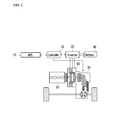
- FIG. 1 is an exemplary block diagram of a system of controlling a motor for reducing vibration of an electric vehicle according to an exemplary embodiment of the present invention.
- a system of controlling a motor for reducing vibration of an electric vehicle an exemplary embodiment of the present invention may include an accelerator pedal position sensor 10, a controller 20, an inverter 30, a battery 40, an engine 50, a driving motor 60 and a transmission 70.
- the accelerator pedal position sensor (APS) 10 may be configured to continuously detect a position value of an accelerator pedal and transmit a monitoring signal to the controller 20.
- the position value of the accelerator pedal may be about 100% when the accelerator pedal is pressed fully (e.g., fully engaged), and the position value of the accelerator pedal may be about 0 % when the accelerator pedal is disengaged.
- the controller 20 may be configured to determine that the driver intends to accelerate, and calculate a demand torque of the driver. Additionally, when the position value of the accelerator pedal is about 0%, the controller 20 may be configured to determine that a minimum demand torque of the driver is a creep torque which is a minimum torque based on creep driving of the vehicle.
- a throttle valve position sensor (TPS) mounted on an intake pipe may be used instead of the accelerator pedal position sensor 10. Therefore, in this specification and the scope of the appended claims, the accelerator pedal position sensor 10 may include the throttle valve position sensor, and the position value of the accelerator pedal should be understood to be an opening value of the throttle valve.
- the inverter 30 may be configured to drive or operate the driving motor 60 by converting a direct-current (DC) voltage supplied from the battery 40 into a three-phase alternating voltage in response to a control signal from the controller 20.
- the inverter 30 may be composed of a plurality of power switching elements and the power switching elements of the inverter 30 may each be implemented by any one of an IGBT (insulated gate bipolar transistor), a MOSFET, a transistor, and a relay.
- IGBT insulated gate bipolar transistor
- the battery 40 may be formed with a plurality of unit cells, and a high voltage for providing a driving voltage to the driving motor 60 may be stored in the battery 40.
- the battery 40 may be operated by a battery management system (not shown) according to a charging state, and may be prevented from overcharging under a critical voltage or over a critical voltage.
- the engine 50 mounted within a hybrid electric vehicle may be configured to output power as a power source while turning on based on a control signal from the controller 20.
- the driving motor 60 may be operated by a three-phase alternating current (AC) voltage applied from the inverter 30 to generate torque, and may operate as a power generator and supply regenerative energy to the battery 40 during coasting.
- AC alternating current
- the transmission 70 may be configured to adjust a shift ratio by operating engagement elements and disengagement elements, using hydraulic pressure according to a control signal from the controller 20.
- the engine clutch (not shown) may be disposed between the engine 50 and the driving motor 60 to provide an EV mode and an HEV mode.
- the controller 20 may be configured to calculate a virtual position value of the accelerator pedal limited to an increasing slope or a descending slope based on the position value of the accelerator pedal detected by the accelerator pedal position sensor 10.
- the controller 20 may use a high pass filter or a low pass filter to calculate the virtual position value of the accelerator pedal.
- the controller 20 may be configured to calculate a vibration reduction torque gain based on the virtual position value of the accelerator pedal, and output a final torque of the driving motor 60 to which applied the vibration reduction torque gain.
- the controller 20 may be configured to calculate the final torque of the driving motor 60 based on a maximum output torque of the driving motor 60 and a vibration reduction torque to which applied the vibration reduction torque gain.
- the vibration reduction torque gain may be set to a maximum value when the position value of the accelerator pedal is about 0%, and may be set to a minimum value when the position value of the accelerator pedal is about 100%.
- the controller 20 may be implemented as at least one processor operated by a predetermined program, and the predetermined program may be programmed to perform each step of a method for controlling a motor for reducing vibration of an electric vehicle according to an exemplary embodiment of the present invention.
- FIG. 2 is an exemplary flowchart showing a method of controlling a motor for reducing vibration of an electric vehicle according to an exemplary embodiment of the present invention.
- a method of controlling a motor for reducing vibration of an electric vehicle according to an exemplary embodiment of the present invention may begin with detecting a position value of an accelerator pedal at step S100.
- the controller 20 may be configured to determine that the driver intends to accelerate (e.g., an acceleration intention). Additionally, when the position value of the accelerator pedal is about 0%, the controller may be configured to determine that the driver does not intend to accelerate (e.g., a non-acceleration intention), thus requiring the creep torque which is a minimum torque based on a vehicle speed. Therefore, the driving motor 60 may be preventing from outputting a demand torque of the driving motor and the controller 20 may be configured to reduce vibration substantially by using the vibration reduction torque. Accordingly, when the position value of the accelerator pedal is about 0%, the vibration reduction torque gain may be set to a maximum value (e.g., 1).
- the driving motor 60 may be configured to output the motor torque.
- a maximum output torque of the driving motor may be demanded.
- the vibration reduction torque may be omitted.
- the vibration reduction torque gain may be set to a minimum value (e.g., 0).
- the controller 20 may be configured to calculate a virtual position value of the accelerator pedal limited to an increasing slope or a descending slope based on the position value of the accelerator pedal at step S110.
- the increasing slope or the descending slope of the position value of the accelerator pedal may be rapidly changed when the driver tips in/out on the accelerator pedal (e.g., when the pressure on the accelerator changes). Accordingly, the vibration reduction torque gain may change due to the change of the increasing slope or the descending slope, and thus the controller 20 may be configured to limit the increasing slope or the descending slope to calculate the virtual position value of the accelerator pedal.
- the controller 20 may be configured to apply a vibration reduction torque gain based on the virtual position value of the accelerator pedal at step S120.
- the vibration reduction torque gain may be set as a value from about 0 to 1.
- the controller 20 may be configured to output a final torque of the driving motor 60 to which applied the vibration reduction torque gain at step S130.
- the final torque of the driving motor 60 may be calculated based on a maximum output torque of the driving motor 60 and a vibration reduction torque to which applied the vibration reduction torque gain.
- FIG. 3 is an exemplary graph showing a comparison result between an output torque of a motor according to a related art and an output torque of a motor according to an exemplary embodiment of the present invention.
- a motor torque may be decreased from a maximum value as a motor output increases when the driver requests a maximum output torque of the motor.
- the output torque of the motor according to an exemplary embodiment of the present invention may be greater than the output torque of the motor according to a related art.
- a shortage phenomenon of output of the driving motor may be prevented by reducing vibration of the motor even when the driver requests a maximum output torque of the driving motor.
Landscapes
- Engineering & Computer Science (AREA)
- Transportation (AREA)
- Mechanical Engineering (AREA)
- Power Engineering (AREA)
- Automation & Control Theory (AREA)
- Chemical & Material Sciences (AREA)
- Combustion & Propulsion (AREA)
- Life Sciences & Earth Sciences (AREA)
- Sustainable Development (AREA)
- Sustainable Energy (AREA)
- Electric Propulsion And Braking For Vehicles (AREA)
Applications Claiming Priority (1)
| Application Number | Priority Date | Filing Date | Title |
|---|---|---|---|
| KR1020140126193A KR20160034773A (ko) | 2014-09-22 | 2014-09-22 | 전기 자동차의 모터 진동 저감 제어 장치 및 방법 |
Publications (2)
| Publication Number | Publication Date |
|---|---|
| EP2998154A1 true EP2998154A1 (fr) | 2016-03-23 |
| EP2998154B1 EP2998154B1 (fr) | 2017-05-17 |
Family
ID=52002687
Family Applications (1)
| Application Number | Title | Priority Date | Filing Date |
|---|---|---|---|
| EP14194115.3A Active EP2998154B1 (fr) | 2014-09-22 | 2014-11-20 | Système et procédé de commande de moteur pour réduire les vibrations d'un véhicule électrique |
Country Status (4)
| Country | Link |
|---|---|
| US (1) | US9327614B2 (fr) |
| EP (1) | EP2998154B1 (fr) |
| KR (1) | KR20160034773A (fr) |
| CN (1) | CN105691235B (fr) |
Cited By (6)
| Publication number | Priority date | Publication date | Assignee | Title |
|---|---|---|---|---|
| CN109062035A (zh) * | 2017-10-16 | 2018-12-21 | 华晨汽车集团控股有限公司 | 一种电动汽车动力总成震荡辨识与抑制方法 |
| CN110366512A (zh) * | 2017-02-23 | 2019-10-22 | 马自达汽车株式会社 | 混合动力车辆的动力控制方法及动力控制装置 |
| US11235749B2 (en) | 2017-02-23 | 2022-02-01 | Mazda Motor Corporation | Driving force control method and device for hybrid vehicle |
| US11312355B2 (en) | 2017-02-23 | 2022-04-26 | Mazda Motor Corporation | Driving force control method and device for hybrid vehicle |
| CN114537154A (zh) * | 2020-11-26 | 2022-05-27 | 无锡蓝海华腾技术有限公司 | 电动车辆扭矩控制方法、装置、电动车辆及可读存储介质 |
| US11351982B2 (en) | 2017-02-23 | 2022-06-07 | Mazda Motor Corporation | Driving force control method and device for hybrid vehicle |
Families Citing this family (8)
| Publication number | Priority date | Publication date | Assignee | Title |
|---|---|---|---|---|
| KR102383236B1 (ko) * | 2016-12-13 | 2022-04-05 | 현대자동차 주식회사 | 하이브리드 차량의 진동 제어 장치 및 방법 |
| KR102485380B1 (ko) * | 2017-11-30 | 2023-01-05 | 현대자동차주식회사 | 차량용 알터네이터 제어 장치 및 그 방법 |
| KR102506763B1 (ko) * | 2018-03-09 | 2023-03-07 | 현대자동차주식회사 | 구동 모터를 구비한 차량 및 그 제어 장치 |
| KR102463487B1 (ko) * | 2018-06-04 | 2022-11-03 | 현대자동차주식회사 | 친환경자동차의 구동 토크 지령 생성 장치 및 방법 |
| KR102529518B1 (ko) * | 2018-06-22 | 2023-05-04 | 현대자동차주식회사 | 친환경자동차의 구동 토크 지령 생성 장치 및 방법 |
| CN110154775B (zh) * | 2019-05-07 | 2022-06-10 | 东风柳州汽车有限公司 | 电动汽车的再生制动能量回收控制方法 |
| CN111409450B (zh) * | 2020-03-31 | 2022-03-15 | 东风航盛(武汉)汽车控制系统有限公司 | 一种车辆的单踏板模式控制方法 |
| CN112198864B (zh) * | 2020-09-28 | 2021-08-31 | 中国汽车工程研究院股份有限公司 | 用于试验车的加速踏板和制动踏板信号控制装置 |
Citations (4)
| Publication number | Priority date | Publication date | Assignee | Title |
|---|---|---|---|---|
| US6232733B1 (en) * | 1998-07-28 | 2001-05-15 | Denso Corporation | Engine-motor hybrid vehicle control apparatus and method having power transmission device operation compensation function |
| US20010020789A1 (en) * | 2000-03-07 | 2001-09-13 | Jatco Transtechnology Ltd. | Parallel hybrid vehicle employing parallel hybrid system, using both internal combustion engine and electric motor generator for propulsion |
| JP2009106099A (ja) * | 2007-10-24 | 2009-05-14 | Nissan Motor Co Ltd | 電動機の制御装置およびその制御方法 |
| JP2011219008A (ja) * | 2010-04-12 | 2011-11-04 | Toyota Motor Corp | 自動車およびその制御方法 |
Family Cites Families (11)
| Publication number | Priority date | Publication date | Assignee | Title |
|---|---|---|---|---|
| JPS60164629A (ja) * | 1984-02-07 | 1985-08-27 | Nissan Motor Co Ltd | スロツトル制御装置 |
| JP3690978B2 (ja) | 2000-11-10 | 2005-08-31 | ダイハツ工業株式会社 | ハイブリッド車両の走行駆動制御装置 |
| KR20040002090A (ko) | 2002-06-29 | 2004-01-07 | 현대자동차주식회사 | 하이브리드 전기자동차의 모터 제어장치 및 방법 |
| CN101200170B (zh) * | 2006-12-11 | 2010-06-16 | 比亚迪股份有限公司 | 电动汽车油门加速装置及方法 |
| JP2009106021A (ja) * | 2007-10-22 | 2009-05-14 | Toyota Motor Corp | 回転電機制御装置 |
| JP2009247157A (ja) | 2008-03-31 | 2009-10-22 | Toyota Motor Corp | 車両の駆動力制御装置 |
| KR101117970B1 (ko) * | 2009-11-06 | 2012-02-15 | 기아자동차주식회사 | 하이브리드 차량의 안티 저크 제어 장치 및 방법 |
| JP5573456B2 (ja) * | 2010-07-23 | 2014-08-20 | 日産自動車株式会社 | 電動車両の制振制御装置および電動車両の制振制御方法 |
| JP2012214179A (ja) | 2011-04-01 | 2012-11-08 | Toyota Motor Corp | ハイブリッド車 |
| JP5817487B2 (ja) * | 2011-12-09 | 2015-11-18 | スズキ株式会社 | 車両用エンジンの吸気装置 |
| KR101449112B1 (ko) * | 2012-08-10 | 2014-10-08 | 현대자동차주식회사 | 전기 자동차의 모터 토크 제어를 이용한 노면 요철 통과 시 발생하는 파워 트레인의 진동 저감 |
-
2014
- 2014-09-22 KR KR1020140126193A patent/KR20160034773A/ko active Search and Examination
- 2014-11-20 EP EP14194115.3A patent/EP2998154B1/fr active Active
- 2014-11-21 US US14/549,588 patent/US9327614B2/en active Active
- 2014-11-28 CN CN201410713203.5A patent/CN105691235B/zh active Active
Patent Citations (4)
| Publication number | Priority date | Publication date | Assignee | Title |
|---|---|---|---|---|
| US6232733B1 (en) * | 1998-07-28 | 2001-05-15 | Denso Corporation | Engine-motor hybrid vehicle control apparatus and method having power transmission device operation compensation function |
| US20010020789A1 (en) * | 2000-03-07 | 2001-09-13 | Jatco Transtechnology Ltd. | Parallel hybrid vehicle employing parallel hybrid system, using both internal combustion engine and electric motor generator for propulsion |
| JP2009106099A (ja) * | 2007-10-24 | 2009-05-14 | Nissan Motor Co Ltd | 電動機の制御装置およびその制御方法 |
| JP2011219008A (ja) * | 2010-04-12 | 2011-11-04 | Toyota Motor Corp | 自動車およびその制御方法 |
Cited By (9)
| Publication number | Priority date | Publication date | Assignee | Title |
|---|---|---|---|---|
| CN110366512A (zh) * | 2017-02-23 | 2019-10-22 | 马自达汽车株式会社 | 混合动力车辆的动力控制方法及动力控制装置 |
| EP3575168A4 (fr) * | 2017-02-23 | 2020-06-24 | Mazda Motor Corporation | Procédé et dispositif de commande d'entraînement pour véhicule hybride |
| US11235749B2 (en) | 2017-02-23 | 2022-02-01 | Mazda Motor Corporation | Driving force control method and device for hybrid vehicle |
| US11260846B2 (en) | 2017-02-23 | 2022-03-01 | Mazda Motor Corporation | Driving force control method and device for hybrid vehicle |
| US11312355B2 (en) | 2017-02-23 | 2022-04-26 | Mazda Motor Corporation | Driving force control method and device for hybrid vehicle |
| US11351982B2 (en) | 2017-02-23 | 2022-06-07 | Mazda Motor Corporation | Driving force control method and device for hybrid vehicle |
| CN109062035A (zh) * | 2017-10-16 | 2018-12-21 | 华晨汽车集团控股有限公司 | 一种电动汽车动力总成震荡辨识与抑制方法 |
| CN114537154A (zh) * | 2020-11-26 | 2022-05-27 | 无锡蓝海华腾技术有限公司 | 电动车辆扭矩控制方法、装置、电动车辆及可读存储介质 |
| CN114537154B (zh) * | 2020-11-26 | 2023-07-07 | 无锡蓝海华腾技术有限公司 | 电动车辆扭矩控制方法、装置、电动车辆及可读存储介质 |
Also Published As
| Publication number | Publication date |
|---|---|
| EP2998154B1 (fr) | 2017-05-17 |
| US9327614B2 (en) | 2016-05-03 |
| US20160082862A1 (en) | 2016-03-24 |
| CN105691235A (zh) | 2016-06-22 |
| KR20160034773A (ko) | 2016-03-30 |
| CN105691235B (zh) | 2019-05-03 |
Similar Documents
| Publication | Publication Date | Title |
|---|---|---|
| EP2998154B1 (fr) | Système et procédé de commande de moteur pour réduire les vibrations d'un véhicule électrique | |
| US10059326B2 (en) | Method of controlling change of travelling mode of hybrid vehicle and control apparatus thereof | |
| US20210276528A1 (en) | System and method for controlling hybrid electric vehicle using driving tendency of driver | |
| US10272908B2 (en) | Method and device for controlling engine clutch of hybrid vehicle | |
| CN106256637B (zh) | 用于混合动力车辆的驾驶模式控制的系统和方法 | |
| CN106256627B (zh) | 用于在混合动力车辆中控制发动机启动时间的方法和装置 | |
| US20130325230A1 (en) | Apparatus and method of controlling motor torque for environment friendly vehicle | |
| US10207702B2 (en) | System and method of controlling shift for hybrid electric vehicle | |
| US9321453B2 (en) | Engine clutch control system for hybrid vehicle and method of controlling engine clutch | |
| US9475489B2 (en) | Method and system for controlling running mode change for hybrid vehicle | |
| CN106515505B (zh) | 控制电动机以减少电动车的振动的装置和方法 | |
| US9371069B2 (en) | Apparatus and method for controlling engine clutch of hybrid electric vehicle | |
| US20170008529A1 (en) | Method and apparatus of controlling vehicle including driving motor | |
| US20160025160A1 (en) | Apparatus and method for determining engine clutch transfer torque of environmentally-friendly vehicle | |
| US9827973B2 (en) | Method and device for learning engine clutch delivery torque of hybrid vehicle | |
| US9592824B1 (en) | Method and device for learning engine clutch kiss point of hybrid vehicle | |
| US20150183418A1 (en) | Apparatus and method for controlling full load mode of hybrid electric vehicle | |
| US9376105B2 (en) | Apparatus and method for controlling engine clutch of hybrid electric vehicle | |
| US9789866B2 (en) | Apparatus and method for controlling mode change of hybrid electric vehicle | |
| US10106147B2 (en) | Method and device for controlling torque intervention of hybrid vehicle | |
| US9738270B1 (en) | Apparatus and method for controlling engine clutch of hybrid vehicle | |
| US9469295B2 (en) | Apparatus and method for controlling mode change of hybrid electric vehicle | |
| US9610953B2 (en) | System and method for controlling regenerative braking |
Legal Events
| Date | Code | Title | Description |
|---|---|---|---|
| PUAI | Public reference made under article 153(3) epc to a published international application that has entered the european phase |
Free format text: ORIGINAL CODE: 0009012 |
|
| AK | Designated contracting states |
Kind code of ref document: A1 Designated state(s): AL AT BE BG CH CY CZ DE DK EE ES FI FR GB GR HR HU IE IS IT LI LT LU LV MC MK MT NL NO PL PT RO RS SE SI SK SM TR |
|
| AX | Request for extension of the european patent |
Extension state: BA ME |
|
| 17P | Request for examination filed |
Effective date: 20160923 |
|
| RBV | Designated contracting states (corrected) |
Designated state(s): AL AT BE BG CH CY CZ DE DK EE ES FI FR GB GR HR HU IE IS IT LI LT LU LV MC MK MT NL NO PL PT RO RS SE SI SK SM TR |
|
| RIC1 | Information provided on ipc code assigned before grant |
Ipc: B60W 10/08 20060101ALI20161031BHEP Ipc: B60L 15/20 20060101AFI20161031BHEP Ipc: B60L 3/00 20060101ALI20161031BHEP |
|
| GRAP | Despatch of communication of intention to grant a patent |
Free format text: ORIGINAL CODE: EPIDOSNIGR1 |
|
| STAA | Information on the status of an ep patent application or granted ep patent |
Free format text: STATUS: GRANT OF PATENT IS INTENDED |
|
| RIN1 | Information on inventor provided before grant (corrected) |
Inventor name: SHIN, DEOK KEUN Inventor name: SHIN, JINCHEOL Inventor name: CHO, WOOCHEOL |
|
| INTG | Intention to grant announced |
Effective date: 20170103 |
|
| GRAS | Grant fee paid |
Free format text: ORIGINAL CODE: EPIDOSNIGR3 |
|
| GRAA | (expected) grant |
Free format text: ORIGINAL CODE: 0009210 |
|
| STAA | Information on the status of an ep patent application or granted ep patent |
Free format text: STATUS: THE PATENT HAS BEEN GRANTED |
|
| AK | Designated contracting states |
Kind code of ref document: B1 Designated state(s): AL AT BE BG CH CY CZ DE DK EE ES FI FR GB GR HR HU IE IS IT LI LT LU LV MC MK MT NL NO PL PT RO RS SE SI SK SM TR |
|
| REG | Reference to a national code |
Ref country code: GB Ref legal event code: FG4D |
|
| REG | Reference to a national code |
Ref country code: CH Ref legal event code: EP |
|
| REG | Reference to a national code |
Ref country code: IE Ref legal event code: FG4D |
|
| REG | Reference to a national code |
Ref country code: AT Ref legal event code: REF Ref document number: 894138 Country of ref document: AT Kind code of ref document: T Effective date: 20170615 |
|
| REG | Reference to a national code |
Ref country code: DE Ref legal event code: R096 Ref document number: 602014009877 Country of ref document: DE |
|
| REG | Reference to a national code |
Ref country code: NL Ref legal event code: MP Effective date: 20170517 |
|
| REG | Reference to a national code |
Ref country code: LT Ref legal event code: MG4D |
|
| REG | Reference to a national code |
Ref country code: AT Ref legal event code: MK05 Ref document number: 894138 Country of ref document: AT Kind code of ref document: T Effective date: 20170517 |
|
| REG | Reference to a national code |
Ref country code: FR Ref legal event code: PLFP Year of fee payment: 4 |
|
| PG25 | Lapsed in a contracting state [announced via postgrant information from national office to epo] |
Ref country code: ES Free format text: LAPSE BECAUSE OF FAILURE TO SUBMIT A TRANSLATION OF THE DESCRIPTION OR TO PAY THE FEE WITHIN THE PRESCRIBED TIME-LIMIT Effective date: 20170517 Ref country code: NO Free format text: LAPSE BECAUSE OF FAILURE TO SUBMIT A TRANSLATION OF THE DESCRIPTION OR TO PAY THE FEE WITHIN THE PRESCRIBED TIME-LIMIT Effective date: 20170817 Ref country code: FI Free format text: LAPSE BECAUSE OF FAILURE TO SUBMIT A TRANSLATION OF THE DESCRIPTION OR TO PAY THE FEE WITHIN THE PRESCRIBED TIME-LIMIT Effective date: 20170517 Ref country code: LT Free format text: LAPSE BECAUSE OF FAILURE TO SUBMIT A TRANSLATION OF THE DESCRIPTION OR TO PAY THE FEE WITHIN THE PRESCRIBED TIME-LIMIT Effective date: 20170517 Ref country code: AT Free format text: LAPSE BECAUSE OF FAILURE TO SUBMIT A TRANSLATION OF THE DESCRIPTION OR TO PAY THE FEE WITHIN THE PRESCRIBED TIME-LIMIT Effective date: 20170517 Ref country code: HR Free format text: LAPSE BECAUSE OF FAILURE TO SUBMIT A TRANSLATION OF THE DESCRIPTION OR TO PAY THE FEE WITHIN THE PRESCRIBED TIME-LIMIT Effective date: 20170517 Ref country code: GR Free format text: LAPSE BECAUSE OF FAILURE TO SUBMIT A TRANSLATION OF THE DESCRIPTION OR TO PAY THE FEE WITHIN THE PRESCRIBED TIME-LIMIT Effective date: 20170818 |
|
| PG25 | Lapsed in a contracting state [announced via postgrant information from national office to epo] |
Ref country code: RS Free format text: LAPSE BECAUSE OF FAILURE TO SUBMIT A TRANSLATION OF THE DESCRIPTION OR TO PAY THE FEE WITHIN THE PRESCRIBED TIME-LIMIT Effective date: 20170517 Ref country code: PL Free format text: LAPSE BECAUSE OF FAILURE TO SUBMIT A TRANSLATION OF THE DESCRIPTION OR TO PAY THE FEE WITHIN THE PRESCRIBED TIME-LIMIT Effective date: 20170517 Ref country code: LV Free format text: LAPSE BECAUSE OF FAILURE TO SUBMIT A TRANSLATION OF THE DESCRIPTION OR TO PAY THE FEE WITHIN THE PRESCRIBED TIME-LIMIT Effective date: 20170517 Ref country code: BG Free format text: LAPSE BECAUSE OF FAILURE TO SUBMIT A TRANSLATION OF THE DESCRIPTION OR TO PAY THE FEE WITHIN THE PRESCRIBED TIME-LIMIT Effective date: 20170817 Ref country code: IS Free format text: LAPSE BECAUSE OF FAILURE TO SUBMIT A TRANSLATION OF THE DESCRIPTION OR TO PAY THE FEE WITHIN THE PRESCRIBED TIME-LIMIT Effective date: 20170917 Ref country code: NL Free format text: LAPSE BECAUSE OF FAILURE TO SUBMIT A TRANSLATION OF THE DESCRIPTION OR TO PAY THE FEE WITHIN THE PRESCRIBED TIME-LIMIT Effective date: 20170517 Ref country code: SE Free format text: LAPSE BECAUSE OF FAILURE TO SUBMIT A TRANSLATION OF THE DESCRIPTION OR TO PAY THE FEE WITHIN THE PRESCRIBED TIME-LIMIT Effective date: 20170517 |
|
| PG25 | Lapsed in a contracting state [announced via postgrant information from national office to epo] |
Ref country code: DK Free format text: LAPSE BECAUSE OF FAILURE TO SUBMIT A TRANSLATION OF THE DESCRIPTION OR TO PAY THE FEE WITHIN THE PRESCRIBED TIME-LIMIT Effective date: 20170517 Ref country code: SK Free format text: LAPSE BECAUSE OF FAILURE TO SUBMIT A TRANSLATION OF THE DESCRIPTION OR TO PAY THE FEE WITHIN THE PRESCRIBED TIME-LIMIT Effective date: 20170517 Ref country code: RO Free format text: LAPSE BECAUSE OF FAILURE TO SUBMIT A TRANSLATION OF THE DESCRIPTION OR TO PAY THE FEE WITHIN THE PRESCRIBED TIME-LIMIT Effective date: 20170517 Ref country code: EE Free format text: LAPSE BECAUSE OF FAILURE TO SUBMIT A TRANSLATION OF THE DESCRIPTION OR TO PAY THE FEE WITHIN THE PRESCRIBED TIME-LIMIT Effective date: 20170517 Ref country code: CZ Free format text: LAPSE BECAUSE OF FAILURE TO SUBMIT A TRANSLATION OF THE DESCRIPTION OR TO PAY THE FEE WITHIN THE PRESCRIBED TIME-LIMIT Effective date: 20170517 |
|
| REG | Reference to a national code |
Ref country code: DE Ref legal event code: R097 Ref document number: 602014009877 Country of ref document: DE |
|
| PG25 | Lapsed in a contracting state [announced via postgrant information from national office to epo] |
Ref country code: SM Free format text: LAPSE BECAUSE OF FAILURE TO SUBMIT A TRANSLATION OF THE DESCRIPTION OR TO PAY THE FEE WITHIN THE PRESCRIBED TIME-LIMIT Effective date: 20170517 Ref country code: IT Free format text: LAPSE BECAUSE OF FAILURE TO SUBMIT A TRANSLATION OF THE DESCRIPTION OR TO PAY THE FEE WITHIN THE PRESCRIBED TIME-LIMIT Effective date: 20170517 |
|
| PLBE | No opposition filed within time limit |
Free format text: ORIGINAL CODE: 0009261 |
|
| STAA | Information on the status of an ep patent application or granted ep patent |
Free format text: STATUS: NO OPPOSITION FILED WITHIN TIME LIMIT |
|
| 26N | No opposition filed |
Effective date: 20180220 |
|
| PG25 | Lapsed in a contracting state [announced via postgrant information from national office to epo] |
Ref country code: SI Free format text: LAPSE BECAUSE OF FAILURE TO SUBMIT A TRANSLATION OF THE DESCRIPTION OR TO PAY THE FEE WITHIN THE PRESCRIBED TIME-LIMIT Effective date: 20170517 |
|
| PG25 | Lapsed in a contracting state [announced via postgrant information from national office to epo] |
Ref country code: MC Free format text: LAPSE BECAUSE OF FAILURE TO SUBMIT A TRANSLATION OF THE DESCRIPTION OR TO PAY THE FEE WITHIN THE PRESCRIBED TIME-LIMIT Effective date: 20170517 |
|
| PG25 | Lapsed in a contracting state [announced via postgrant information from national office to epo] |
Ref country code: CH Free format text: LAPSE BECAUSE OF NON-PAYMENT OF DUE FEES Effective date: 20171130 Ref country code: LI Free format text: LAPSE BECAUSE OF NON-PAYMENT OF DUE FEES Effective date: 20171130 |
|
| PG25 | Lapsed in a contracting state [announced via postgrant information from national office to epo] |
Ref country code: LU Free format text: LAPSE BECAUSE OF NON-PAYMENT OF DUE FEES Effective date: 20171120 |
|
| REG | Reference to a national code |
Ref country code: BE Ref legal event code: MM Effective date: 20171130 |
|
| REG | Reference to a national code |
Ref country code: IE Ref legal event code: MM4A |
|
| PG25 | Lapsed in a contracting state [announced via postgrant information from national office to epo] |
Ref country code: MT Free format text: LAPSE BECAUSE OF NON-PAYMENT OF DUE FEES Effective date: 20171120 |
|
| REG | Reference to a national code |
Ref country code: FR Ref legal event code: PLFP Year of fee payment: 5 |
|
| PG25 | Lapsed in a contracting state [announced via postgrant information from national office to epo] |
Ref country code: IE Free format text: LAPSE BECAUSE OF NON-PAYMENT OF DUE FEES Effective date: 20171120 |
|
| PG25 | Lapsed in a contracting state [announced via postgrant information from national office to epo] |
Ref country code: BE Free format text: LAPSE BECAUSE OF NON-PAYMENT OF DUE FEES Effective date: 20171130 |
|
| PG25 | Lapsed in a contracting state [announced via postgrant information from national office to epo] |
Ref country code: HU Free format text: LAPSE BECAUSE OF FAILURE TO SUBMIT A TRANSLATION OF THE DESCRIPTION OR TO PAY THE FEE WITHIN THE PRESCRIBED TIME-LIMIT; INVALID AB INITIO Effective date: 20141120 |
|
| PG25 | Lapsed in a contracting state [announced via postgrant information from national office to epo] |
Ref country code: CY Free format text: LAPSE BECAUSE OF FAILURE TO SUBMIT A TRANSLATION OF THE DESCRIPTION OR TO PAY THE FEE WITHIN THE PRESCRIBED TIME-LIMIT Effective date: 20170517 |
|
| PG25 | Lapsed in a contracting state [announced via postgrant information from national office to epo] |
Ref country code: MK Free format text: LAPSE BECAUSE OF FAILURE TO SUBMIT A TRANSLATION OF THE DESCRIPTION OR TO PAY THE FEE WITHIN THE PRESCRIBED TIME-LIMIT Effective date: 20170517 |
|
| PG25 | Lapsed in a contracting state [announced via postgrant information from national office to epo] |
Ref country code: TR Free format text: LAPSE BECAUSE OF FAILURE TO SUBMIT A TRANSLATION OF THE DESCRIPTION OR TO PAY THE FEE WITHIN THE PRESCRIBED TIME-LIMIT Effective date: 20170517 |
|
| PG25 | Lapsed in a contracting state [announced via postgrant information from national office to epo] |
Ref country code: PT Free format text: LAPSE BECAUSE OF FAILURE TO SUBMIT A TRANSLATION OF THE DESCRIPTION OR TO PAY THE FEE WITHIN THE PRESCRIBED TIME-LIMIT Effective date: 20170517 |
|
| PG25 | Lapsed in a contracting state [announced via postgrant information from national office to epo] |
Ref country code: AL Free format text: LAPSE BECAUSE OF FAILURE TO SUBMIT A TRANSLATION OF THE DESCRIPTION OR TO PAY THE FEE WITHIN THE PRESCRIBED TIME-LIMIT Effective date: 20170517 |
|
| P01 | Opt-out of the competence of the unified patent court (upc) registered |
Effective date: 20230526 |
|
| PGFP | Annual fee paid to national office [announced via postgrant information from national office to epo] |
Ref country code: GB Payment date: 20231023 Year of fee payment: 10 |
|
| PGFP | Annual fee paid to national office [announced via postgrant information from national office to epo] |
Ref country code: FR Payment date: 20231024 Year of fee payment: 10 Ref country code: DE Payment date: 20231023 Year of fee payment: 10 |