EP2997927A2 - Système de détermination et de suivi de mouvement au cours d'une procédure médicale - Google Patents
Système de détermination et de suivi de mouvement au cours d'une procédure médicale Download PDFInfo
- Publication number
- EP2997927A2 EP2997927A2 EP15185062.5A EP15185062A EP2997927A2 EP 2997927 A2 EP2997927 A2 EP 2997927A2 EP 15185062 A EP15185062 A EP 15185062A EP 2997927 A2 EP2997927 A2 EP 2997927A2
- Authority
- EP
- European Patent Office
- Prior art keywords
- tracking
- pattern
- patterns
- fixture
- optically visible
- Prior art date
- Legal status (The legal status is an assumption and is not a legal conclusion. Google has not performed a legal analysis and makes no representation as to the accuracy of the status listed.)
- Granted
Links
- 238000000034 method Methods 0.000 title claims abstract description 26
- 230000033001 locomotion Effects 0.000 title description 15
- 238000001356 surgical procedure Methods 0.000 claims abstract description 21
- 238000012545 processing Methods 0.000 claims abstract description 20
- 230000008569 process Effects 0.000 claims abstract description 13
- 210000003484 anatomy Anatomy 0.000 claims abstract description 5
- 238000007373 indentation Methods 0.000 claims description 10
- 230000000712 assembly Effects 0.000 claims description 2
- 238000000429 assembly Methods 0.000 claims description 2
- 239000000463 material Substances 0.000 description 27
- 210000000214 mouth Anatomy 0.000 description 22
- 238000002591 computed tomography Methods 0.000 description 10
- PXFBZOLANLWPMH-UHFFFAOYSA-N 16-Epiaffinine Natural products C1C(C2=CC=CC=C2N2)=C2C(=O)CC2C(=CC)CN(C)C1C2CO PXFBZOLANLWPMH-UHFFFAOYSA-N 0.000 description 9
- 238000001514 detection method Methods 0.000 description 8
- 238000002675 image-guided surgery Methods 0.000 description 8
- 230000003287 optical effect Effects 0.000 description 8
- 239000003086 colorant Substances 0.000 description 7
- 239000011159 matrix material Substances 0.000 description 7
- 230000008901 benefit Effects 0.000 description 5
- 230000007246 mechanism Effects 0.000 description 5
- 230000009466 transformation Effects 0.000 description 5
- 230000008859 change Effects 0.000 description 4
- 230000006870 function Effects 0.000 description 4
- 239000013598 vector Substances 0.000 description 4
- 230000018109 developmental process Effects 0.000 description 3
- 238000003384 imaging method Methods 0.000 description 3
- 230000000007 visual effect Effects 0.000 description 3
- 238000004458 analytical method Methods 0.000 description 2
- 210000000988 bone and bone Anatomy 0.000 description 2
- 238000007796 conventional method Methods 0.000 description 2
- 238000012937 correction Methods 0.000 description 2
- 238000011161 development Methods 0.000 description 2
- 238000005553 drilling Methods 0.000 description 2
- 210000003128 head Anatomy 0.000 description 2
- 238000005286 illumination Methods 0.000 description 2
- 238000012986 modification Methods 0.000 description 2
- 230000004048 modification Effects 0.000 description 2
- 238000003860 storage Methods 0.000 description 2
- 239000012815 thermoplastic material Substances 0.000 description 2
- 229920000491 Polyphenylsulfone Polymers 0.000 description 1
- -1 Polyvinylsiloxane Polymers 0.000 description 1
- 238000002679 ablation Methods 0.000 description 1
- DHKHKXVYLBGOIT-UHFFFAOYSA-N acetaldehyde Diethyl Acetal Natural products CCOC(C)OCC DHKHKXVYLBGOIT-UHFFFAOYSA-N 0.000 description 1
- 230000006978 adaptation Effects 0.000 description 1
- 230000009286 beneficial effect Effects 0.000 description 1
- 230000037182 bone density Effects 0.000 description 1
- 238000004364 calculation method Methods 0.000 description 1
- 230000015556 catabolic process Effects 0.000 description 1
- 239000000919 ceramic Substances 0.000 description 1
- 238000004040 coloring Methods 0.000 description 1
- 238000004891 communication Methods 0.000 description 1
- 229920001577 copolymer Polymers 0.000 description 1
- 230000007812 deficiency Effects 0.000 description 1
- 238000006731 degradation reaction Methods 0.000 description 1
- 239000004053 dental implant Substances 0.000 description 1
- 239000005457 ice water Substances 0.000 description 1
- 238000003973 irrigation Methods 0.000 description 1
- 230000002262 irrigation Effects 0.000 description 1
- 238000004519 manufacturing process Methods 0.000 description 1
- 239000003550 marker Substances 0.000 description 1
- 230000013011 mating Effects 0.000 description 1
- 238000000465 moulding Methods 0.000 description 1
- 210000005036 nerve Anatomy 0.000 description 1
- 239000004033 plastic Substances 0.000 description 1
- 229920003023 plastic Polymers 0.000 description 1
- 229920001610 polycaprolactone Polymers 0.000 description 1
- 239000004632 polycaprolactone Substances 0.000 description 1
- 230000001737 promoting effect Effects 0.000 description 1
- 238000013138 pruning Methods 0.000 description 1
- 230000003252 repetitive effect Effects 0.000 description 1
- 230000010076 replication Effects 0.000 description 1
- 239000007787 solid Substances 0.000 description 1
- 238000012360 testing method Methods 0.000 description 1
- 229920001187 thermosetting polymer Polymers 0.000 description 1
- 210000004357 third molar Anatomy 0.000 description 1
- 210000001519 tissue Anatomy 0.000 description 1
- 238000013519 translation Methods 0.000 description 1
- 230000000472 traumatic effect Effects 0.000 description 1
- 210000001835 viscera Anatomy 0.000 description 1
- XLYOFNOQVPJJNP-UHFFFAOYSA-N water Substances O XLYOFNOQVPJJNP-UHFFFAOYSA-N 0.000 description 1
Images


Classifications
-
- A—HUMAN NECESSITIES
- A61—MEDICAL OR VETERINARY SCIENCE; HYGIENE
- A61B—DIAGNOSIS; SURGERY; IDENTIFICATION
- A61B90/00—Instruments, implements or accessories specially adapted for surgery or diagnosis and not covered by any of the groups A61B1/00 - A61B50/00, e.g. for luxation treatment or for protecting wound edges
- A61B90/39—Markers, e.g. radio-opaque or breast lesions markers
-
- A—HUMAN NECESSITIES
- A61—MEDICAL OR VETERINARY SCIENCE; HYGIENE
- A61B—DIAGNOSIS; SURGERY; IDENTIFICATION
- A61B34/00—Computer-aided surgery; Manipulators or robots specially adapted for use in surgery
- A61B34/20—Surgical navigation systems; Devices for tracking or guiding surgical instruments, e.g. for frameless stereotaxis
-
- A—HUMAN NECESSITIES
- A61—MEDICAL OR VETERINARY SCIENCE; HYGIENE
- A61B—DIAGNOSIS; SURGERY; IDENTIFICATION
- A61B5/00—Measuring for diagnostic purposes; Identification of persons
- A61B5/0059—Measuring for diagnostic purposes; Identification of persons using light, e.g. diagnosis by transillumination, diascopy, fluorescence
- A61B5/0077—Devices for viewing the surface of the body, e.g. camera, magnifying lens
-
- A—HUMAN NECESSITIES
- A61—MEDICAL OR VETERINARY SCIENCE; HYGIENE
- A61B—DIAGNOSIS; SURGERY; IDENTIFICATION
- A61B6/00—Apparatus or devices for radiation diagnosis; Apparatus or devices for radiation diagnosis combined with radiation therapy equipment
- A61B6/50—Apparatus or devices for radiation diagnosis; Apparatus or devices for radiation diagnosis combined with radiation therapy equipment specially adapted for specific body parts; specially adapted for specific clinical applications
- A61B6/51—Apparatus or devices for radiation diagnosis; Apparatus or devices for radiation diagnosis combined with radiation therapy equipment specially adapted for specific body parts; specially adapted for specific clinical applications for dentistry
-
- A—HUMAN NECESSITIES
- A61—MEDICAL OR VETERINARY SCIENCE; HYGIENE
- A61C—DENTISTRY; APPARATUS OR METHODS FOR ORAL OR DENTAL HYGIENE
- A61C1/00—Dental machines for boring or cutting ; General features of dental machines or apparatus, e.g. hand-piece design
- A61C1/08—Machine parts specially adapted for dentistry
- A61C1/082—Positioning or guiding, e.g. of drills
-
- A—HUMAN NECESSITIES
- A61—MEDICAL OR VETERINARY SCIENCE; HYGIENE
- A61C—DENTISTRY; APPARATUS OR METHODS FOR ORAL OR DENTAL HYGIENE
- A61C9/00—Impression cups, i.e. impression trays; Impression methods
- A61C9/004—Means or methods for taking digitized impressions
- A61C9/0046—Data acquisition means or methods
-
- A—HUMAN NECESSITIES
- A61—MEDICAL OR VETERINARY SCIENCE; HYGIENE
- A61B—DIAGNOSIS; SURGERY; IDENTIFICATION
- A61B34/00—Computer-aided surgery; Manipulators or robots specially adapted for use in surgery
- A61B34/20—Surgical navigation systems; Devices for tracking or guiding surgical instruments, e.g. for frameless stereotaxis
- A61B2034/2046—Tracking techniques
- A61B2034/2055—Optical tracking systems
-
- A—HUMAN NECESSITIES
- A61—MEDICAL OR VETERINARY SCIENCE; HYGIENE
- A61B—DIAGNOSIS; SURGERY; IDENTIFICATION
- A61B34/00—Computer-aided surgery; Manipulators or robots specially adapted for use in surgery
- A61B34/20—Surgical navigation systems; Devices for tracking or guiding surgical instruments, e.g. for frameless stereotaxis
- A61B2034/2046—Tracking techniques
- A61B2034/2065—Tracking using image or pattern recognition
-
- A—HUMAN NECESSITIES
- A61—MEDICAL OR VETERINARY SCIENCE; HYGIENE
- A61B—DIAGNOSIS; SURGERY; IDENTIFICATION
- A61B90/00—Instruments, implements or accessories specially adapted for surgery or diagnosis and not covered by any of the groups A61B1/00 - A61B50/00, e.g. for luxation treatment or for protecting wound edges
- A61B90/36—Image-producing devices or illumination devices not otherwise provided for
- A61B2090/363—Use of fiducial points
-
- A—HUMAN NECESSITIES
- A61—MEDICAL OR VETERINARY SCIENCE; HYGIENE
- A61B—DIAGNOSIS; SURGERY; IDENTIFICATION
- A61B90/00—Instruments, implements or accessories specially adapted for surgery or diagnosis and not covered by any of the groups A61B1/00 - A61B50/00, e.g. for luxation treatment or for protecting wound edges
- A61B90/39—Markers, e.g. radio-opaque or breast lesions markers
- A61B2090/3937—Visible markers
-
- A—HUMAN NECESSITIES
- A61—MEDICAL OR VETERINARY SCIENCE; HYGIENE
- A61B—DIAGNOSIS; SURGERY; IDENTIFICATION
- A61B90/00—Instruments, implements or accessories specially adapted for surgery or diagnosis and not covered by any of the groups A61B1/00 - A61B50/00, e.g. for luxation treatment or for protecting wound edges
- A61B90/39—Markers, e.g. radio-opaque or breast lesions markers
- A61B2090/3966—Radiopaque markers visible in an X-ray image
-
- A—HUMAN NECESSITIES
- A61—MEDICAL OR VETERINARY SCIENCE; HYGIENE
- A61B—DIAGNOSIS; SURGERY; IDENTIFICATION
- A61B90/00—Instruments, implements or accessories specially adapted for surgery or diagnosis and not covered by any of the groups A61B1/00 - A61B50/00, e.g. for luxation treatment or for protecting wound edges
- A61B90/39—Markers, e.g. radio-opaque or breast lesions markers
- A61B2090/3983—Reference marker arrangements for use with image guided surgery
Definitions
- the present invention relates to a system for image guided surgery and, more particularly, to an system for determining and tracking movement during a medical procedure using an externally visible reference point.
- Image guided surgery has had extensive developments over the years and is now a very important tool in surgical procedures. Most of the developments have centered around imaging locations in the body where there is very little access, such as internal organs.
- Oral surgery which is defined herein as any surgery occurring within the oral cavity, can be just as difficult to conduct visually.
- the oral cavity is relatively small and difficult for a patient to maintain open for prolonged periods of time. Even if a surgical site is visible, once the drill penetrates, it becomes difficult to determine where the tip is at any given time.
- Image guided surgery involves the use of a computed or computerized axial tomography scan, commonly referred to as CT or CAT scans, to create a digital image of the surgical site (typically in three dimensions). The surgeon then creates a plan for the surgery using the image. During surgery, the image generated from the prior CT scan is used in conjunction with a special instrument, to visually depict where the tip of the instrument is inside the patient.
- CT or CAT scans computed or computerized axial tomography scan
- the digital image from the scan must be accurately registered to the surgical site of the patient such that movement of the patient causes adjustment of the digital image.
- the exact location of the instrument tip relative to the patient must also be known.
- CT scans of the patient's teeth are used by the doctors to accurately determine bone density, width and height, as well as understand relationships of other teeth and anatomical structures in order to plan a surgical event to provide the restorative solution that would likely be the most successful and least traumatic.
- Active image guided surgery solves many of the problems of passively guided systems, i.e., limited maximal mouth opening, the need to prefabricate a passive guide and the inability to change the plan during surgery can be overcome by actively guided systems.
- the position of the patient's mouth specifically the bone and teeth, must be accurately tracked and registered to the scanned image and the surgical tool.
- most conventional systems require the creation of a registration device that is attached to the patient's head or inserted into the mouth which includes fiducial markers and a sensor.
- Some registration devices are attached to the outside of the head, for example, a head mounted fixture.
- Others involve a fixture that is attached to the jawbone with the sensors located outside the mouth in order to limit the interference with the surgical zone and to permit optical sensors to track the movement of the fixture and surgical tool.
- an impression is taken, typically of both the upper and lower sets of teeth weeks in advance of the operation.
- the impression is then sent to a lab where a cast is made substantially duplicating the teeth.
- a cast is made substantially duplicating the teeth.
- an oral fixture is made that either seats on the teeth or is designed to be drilled into the jawbone.
- the fixture includes at least the fiducial markers and also, if not fitted with a sensor, includes mounting locations for the optical sensors.
- the lab creates the fixture it is sent back to the dental surgeon.
- the patient is brought in, fitted with the fixture and a CT scan is taken.
- the patient is once again sent home.
- a digital image of the patient's oral cavity is created from the scan and the surgeon develops the surgical plan.
- the patient is then brought in for the operation.
- the fixture is attached to the patient.
- Optical transmitters are located about the patient and emit signals that are detected by the sensor(s).
- the sensor(s) send a signal to the software as the patient's mouth moves and an adjustment is made to the digital image of the patient's oral cavity.
- the software also tracks the position of the instrument and depicts an image of the instrument in the proper location relative to the digital image of the teeth.
- All present dental active image-guided surgery systems involve the use of optical tracking which requires that the fixture that is placed in the patient's mouth extends outside the mouth in order to be detected by the optical transmitter or receivers.
- An image guidance system for tracking a surgical instrument during oral surgery.
- the system includes a fixture configured to be removably attached to a patient's anatomy in a location near a surgical area.
- a first tracking assembly including a bracket assembly, is removably attached to the fixture.
- the first tracking assembly includes a first tracking pattern surface including a first optically visible pattern.
- the bracket assembly positions the first tracking pattern at a location spaced apart from the surgical area.
- the system includes a tool for use in the surgical procedure.
- a second tracking assembly is attached to the tool and includes a second tracking pattern surface.
- the second tracking pattern surface includes a second optically visible pattern.
- a plurality of cameras are mounted away from the surgical area at a position that permits the cameras, when activated, to capture images of the optically visible patterns on the first and second tracking pattern surfaces.
- a processing system is connected to the cameras and processes the captured images.
- the processor is configured to recognize the optically visible patterns and triangulate the locations and orientations of the first and second tracking assemblies.
- the processing system determines the location and orientation of the tracked tool based on a reference dataset that includes the location and orientation of the fixture with respect to a scan such as a CT scan of the surgical area.
- the processing system analyzing relative transforms between each camera of the optically visible patterns on the first and second tracking pattern surfaces.
- the fixture is preferably configured to removably attach to one or more teeth in a patient's mouth.
- the bracket assembly includes a bracket mount that removably attaches to a flange on the fixture.
- the bracket assembly also includes a tracking mount that attaches to the first tracking pattern surface, and a support arm that attaches the bracket mount to the tracking mount.
- the bracket mount preferably includes two spaced apart mounting posts that engage with the flange. The attachment of the tracking mount to the first tracking pattern surface is preferably adjustable.
- the tracking mount includes a base with a series of indentations and protrusions.
- the first tracking assembly includes a frame with an attachment to the tracking mount, the attachment being configured to permit the frame to be adjustable oriented with respect to the bracket assembly.
- the frame may include a series of indentations and protrusions that are configured to mate with the indentations and protrusions on the tracking mount so as to permit rotational orientation of the tracking frame relative to the base to be adjustable.
- the optically visible patterns each preferably contain a plurality of 2D contrasting shapes, the contrasting shapes arranged so as to uniquely differentiate each optically visible pattern from the other optically visible pattern.
- Each camera is located so as to capture at least a portion of the optically visible pattern on each of the first and second tracking pattern surfaces such that an image of each optically visible pattern captured by the camera is at a different viewing angle than the image of the same optically visible pattern captured by the other camera(s).
- the cameras are configured to send data representative of the 2D images of the optically visible patterns captured by the cameras.
- the processor includes a dataset of patterns including location data for contrasting shapes on each of the patterns in the dataset.
- the processor is configured to analyze the dataset of patterns to determine which of the patterns in the dataset corresponds to each of the optically visible patterns in the 2D images received from the cameras.
- the contrasting shapes include adjacent boxes of distinct color, each set of adjacent boxes being separated from one another by a line.
- a defined point is formed by a center point of two intersecting lines, and the processor determines the location of defined points in the dataset of patterns. he optically visible patterns for determining whether a given pattern from the dataset of patterns corresponds to the optically visible patterns.
- the fixture is configured to removably snap onto one or more teeth of the patient.
- the flange extends outward away from wherein the patient's tooth would be located.
- a method for providing image guidance in an oral surgical procedure using the image guidance system described above.
- the present invention addresses the prior art deficiencies by providing an image guidance system for efficiently tracking a patient's movement during surgery.
- the present invention will be described as it related to oral surgery and the tracking of the movement of a patient's mouth, but the invention is not necessarily limited to that embodiment.
- the image guidance system includes a plurality of cameras located outside the oral cavity to provide images of optically visible patterns attached to the patient through an oral fixture and that are located external to the area being operated on. The images are used to detect and tracking movement of the patient's mouth, and/or a surgical instrument or tool.
- a processing system receives and processes the images to recognize patterns and triangulate the locations and orientations relative to each camera.
- the processing system uses a reference dataset which defines a reference coordinate system based on alignment to a portion of the oral anatomy.
- the processing system determines the location and orientation of the tracked surgical instrument and the oral fixture based on the reference dataset.
- the inventive features are not limited to oral surgical procedures and have applicability to other surgical procedures.
- the system 10 includes an oral dental appliance or fixture 12 that is designed to attach to one or more teeth of the patient.
- an oral dental appliance or fixture 12 that is designed to attach to one or more teeth of the patient.
- One suitable fixture is described in co-pending Application Serial No. 14/209,500 , the disclosure of which is incorporated herein by reference in its entirety. Details of the fixture 12 as referenced herein can be found in that application.
- the fixture 12 is preferably removably attachable to the patient's teeth and includes a support 14 that is made from a suitably strong material, preferably a thermoset plastic material, that is sufficiently rigid so as not to deform when subjected to the elevated temperatures discussed below.
- the plastic material is polyphenylsulphone or acetal copolymer.
- the support 14 includes a base 16 that is, preferably, generally planar, with an inner wall 18 and an outer wall 20.
- the inner wall 18 and outer wall 20 are attached to and extend outward from the base 16.
- the walls 18, 20 extend outward from the base 16 at substantially or generally right angles from the base 16. However as will be appreciated the walls could be at other desired angles from the base 16.
- the walls and base are preferably formed as an integral component.
- the spacing of the inner and outer walls 18, 20 is larger than the width of the teeth to which the oral fixture 12 is intended to be attached. It should be readily apparent that the spacing of the walls 18, 20 can be different between fixtures designed for adults and children.
- the walls 18, 20 preferably have a height from the base which extends below the top of the patient's teeth when installed. Preferably the height is sufficient to extend about 10 mm to about 13.5 mm down from occlusal surface when installed on a patient's tooth with the overlying material.
- the oral fixture 12 also includes a moldable thermoplastic material located on an inner surface of the support 14, preferably on the base 16.
- the moldable material is designed to form an impression of a portion of a patient's teeth. More specifically, when the moldable material is in its uncured (unset) state, the material is "activated” by placing the oral fixture 12 (support 14 with moldable material on it) into a bowl of warm or hot water that is at a temperature above which the material begins to become moldable.
- the chosen material has a characteristic that provides the user with a visual indication that the material is ready to be molded, such as changing color (e.g., from white to clear or translucent).
- the oral fixture 12 is placed on a patient's teeth and slight downward pressure is applied causing the moldable material to deform around the top and at least some of the sides of the teeth between the support walls 18, 20. After a prescribed period of time, generally about 30 seconds to one minute, the moldable material sets to form an impression of the outside shape and contours of the teeth that were covered by the material. The oral fixture 12 can then be removed from the patient's mouth. Further curing can be achieved by placing the oral fixture 12 with the mold material into a bowl of cold or ice water to complete the setting process.
- the material selected must remain solid (cured) at temperatures typically existing in a person's mouth (generally, around 100 degrees F), and moldable at a temperature above that (e.g., above 130 degrees F), at least until it is initially set.
- the material should be sufficiently rigid in its cured state so as to maintain the shape of the impression without distorting.
- Suitable thermoplastic materials for use in the inention includes Polycaprolactone or Polyvinylsiloxane (PVS).
- PVS Polycaprolactone or Polyvinylsiloxane
- any type of moldable material that can set and retain an impression can be used in the present invention.
- the moldable material may be flavored to please the patient during the molding process. The amount of material used will vary depending on the number and size of teeth that are to be molded.
- the oral fixture 12 also includes a plurality of fiducial markers 80 mounted on the support 14 in order for the system to determine where the oral fixture 12 (and thus the camera) is relative to the patient's teeth.
- the markers 80 are at certain locations on the fixture 12 and are part of a registration system for properly locating the fixture 12 in space.
- the fiducial markers are detected during a CT scan of the patient's mouth and their location is registered in the scan.
- the fiducial markers may be located on the base 16 and/or the walls 18, 20.
- the fiducial markers 80 may be spherical in shape and/or colored so as to be easily detected by a technician or doctor, as well as the software being used. More specifically, in order for the fiducial markers 80 to be detected in a scanned image, the fiducial markers 80 must have a different radiodensity (i.e., the density that is detected by the CT scan) than the fixture, moldable material and teeth. In one embodiment, the fiducial markers 80 are ceramic ball bearings. However, other materials, shapes and sizes may be used. Preferably the fiducial markers 80 each have their own radiodensity or are of different sizes or shapes so that a software program can be used to automatically detect the different fiducial markers 80 in the scanned image.
- the software may also apply a color in the scanned image that corresponds to the markers color or shape to assist in registration of the oral fixture 12 as will be discussed further below.
- the fiducials can include passive optical attributes, such as specular or diffuse surfaces, or active optical attributes, such as light emitting materials, for use in visually locating the fiducials relative to a camera or other location.
- fiducial markers are distinguished from the teeth and oral fixture 12 by their radiodensity, it is also contemplated that other distinguishing features can be used other than density.
- the markers can be pre-fixed transmitters or other position location devices.
- the oral fixture 12 also includes at least one mount 26 attached to or formed integral with the support 14.
- the mount 26 extends outward from the outer wall 20.
- the mount 26 is configured to have a tracking assembly 200 attached to it for use in tracking motion (position changes) of the fixture 12.
- the mount 26 includes at least one flange 28 and more preferably two spaced apart flanges 28, 30 that extend out of the side of the fixture 12.
- Each flange 28, 30 may include notches or indentations 32 formed in the opposite lateral sides of the flange 28, 30.
- a bracket assembly 100 is removably attachable to the mount 26 of the oral fixture 12 and is configured to hold the tracking assembly 200.
- the bracket assembly includes a bracket mount 102 that removably attaches to the flanges 28, 30 on the fixture, a support arm 104, and a tracking mount 106.
- the bracket mount 102 includes two spaced apart mounting posts 108 A , 108 B .
- Each mounting post 108 preferably includes a protrusion 110 that is configured to engage with and sit in the notch 32 such that the mounting posts 108 A , 108 B are positioned on either side of and against the flanges 28, 30.
- the support arm 104 includes a main portion 112 and a fixture portion 114 that extends between the posts 108 A , 108 B .
- the support arm 104 is rigidly, preferably fixedly, attached to one of the posts 108 A .
- the other post 108 B (the one furthest from the main portion 112) is preferably slidably disposed on the fixture portion 114 so that the spacing between the posts 108 A , 108 B is adjustable.
- a distal end of the fixture portion 114 extends through the post 108 B . Threads (not shown) are preferably formed on the distal end of the fixture portion 114.
- a knob 116 is threaded onto the distal end of the fixture portion. As shown in Fig.
- tracker arm pins 113 are used to attach the posts 108 captive on the support arm 112. This allows the posts 108 to rotate freely about the support arm 112.
- post 108 A is positioned against the flanges 28, 30 so that the protruding portion 110 seats in the notch 32.
- the other post 108 B is slid on the distal end of the fixture portion of the support arm 104 until its protruding portion 110 seats within the other notch 32.
- the knob 116 is tightened, thereby securing the arm 104 to the oral fixture 12.
- the posts 108 could, instead, include notched portions and the flanges 28, 30 could have protruding portions, or the posts and flanges might simply have flush mounting surfaces.
- the opposite end of the arm 104 includes a tracking mount 106 for attaching a fixture tracking assembly 200.
- the tracking mount 106 includes a threaded stub 118 and a base 120.
- the base 120 preferably has a series of teeth or indentations and protrusions 122.
- the base 120 and threaded stub 118 are preferably integral with the main portion 112 of the arm 104.
- the fixture tracking assembly 200 is attached to the tracking mount 106 so that it is preferably adjustable. More particular, the fixture tracking assembly 200 includes a frame 202 which attaches to the tracking mount 106 of the bracket assembly 100. The attachment is preferably configured to permit the frame to adjustably oriented with respect to the bracket assembly 100 as will be discussed in more detail.
- the frame 202 includes a hole 203 (shown in Fig. 4 ) with threads that threadingly engage with the threads on the stub 118 of the arm 104.
- the inclusion of the mating teeth 122/204 permits accurate and repeatable adjustability of the position of the frame 202 relative to the support arm 104.
- the mounting of the fixture tracking assembly 200 to the bracket assembly 100 permits the tracking assembly to be lockably positioned at different positions of rotation about axis 206.
- the tracking assembly includes a pattern display surface 208 that is attached to or formed on the frame 202.
- a pattern display surface 208 that is attached to or formed on the frame 202.
- the pattern display surface can have any suitable shape.
- the pattern display surface 208 of the tracking assembly is substantially cylindrical having an axis that is preferably collinear with the axis 206.
- the pattern display surface 208 of the tracking assembly is substantially flat or planar. It should be readily apparent that any other shape could be used with the present invention.
- a tracking pattern 210 is disposed or formed on the pattern display surface 208.
- the tracking pattern 210 is an optically visible pattern that is configured to provide visual reference points for externally mounted cameras to detect for use by a computer system to track the position and movement of the tracking assembly, and, thus, the oral fixture 12.
- the tracking pattern may include a series of non-repetitive Quick Reference or QR Codes spaced apart on the surface of the tracking assembly 200.
- Application Serial No. 14/209,500 describes some suitable tracking patterns that can be used in the present invention.
- Fig. 10 illustrates a 2D tracking pattern that may be used in the present invention.
- the pattern preferably uses contrasting colors, such as black (shown in dense cross-hatching) and white, to facilitate detection and recognition by the system.
- the arrangement of the checkerboard squares are arranged so as to be easily and quickly identified. It is also contemplated that other mechanisms can be used to provide the reference data needed, including LEDs, a data matrix, data glyphs, or raised or lowered features similar to braille.
- the tracking pattern 208 may be formed on a layer of material that is adhered to the frame of the tracking assembly. Alternatively, the tracking pattern may be molded or etched onto or disposed directly on the frame.
- the fixture tracking assembly 200 may be configured to provide backlighting or other mechanism to increase the contrast of the tracking pattern 210 in order to facilitate detection. If the tracking assembly is backlit, the tracking pattern 210 is preferably made of at least partially transparent or translucent material so as to enhance the contrast. It is also contemplated that a fluorescent material can be used to facilitate detection.
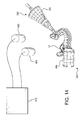
- a surgical tool tracking assembly 300 is shown mounted to or part of a surgical dental tool 302, such as a drill.
- the tool tracking assembly 300 includes a tool mount 304 that is designed to secure a tool pattern surface 306 to the tool 302.
- the tool mount 304 includes an opening 308 that fits around the body 310 of the tool 302 in a secure manner so that the tracking assembly moves in combination with the surgical tool.
- the attachment could be through any of a number of different mechanisms well known in the art.
- the tool tracking assembly is attached, for example, with a collet or similar well known mechanism which may be removably screwed on or clamped down on the tool body so as to secure the tool tracking assembly to the tool.
- a hole may be included to permit irrigation tubes and tool camera wires.
- the tool tracking pattern 308 is an optically visible pattern that is configured to provide visual reference points for externally mounted cameras to detect for use by a computer system to track the position and movement of the tool tracking assembly 300.
- the pattern shown in Fig. 10 could be used as the tool tracking pattern.
- the tracking tile 400 includes a portion of the tracking pattern 210. More specifically, in the illustrated embodiment, when four tracking tiles are arranged as shown in Fig. 11 , the intersection of the four tiles defines the tracking pattern 210 as indicated by the dashed lines.
- the lightly cross-hatched boxes can be either black or white within the scope of the invention. The choices of coloring of the lightly cross-hatched boxes, in combination with other boxes on the tile 400 permit the tile to be uniquely defined so that the pattern on the individual tile 400 is recognized by the system.
- each tile includes, on average, approximately 50% intensity (i.e., 50% light and 50% dark). This facilitates the ability of a computer system detecting, through a camera, the boxes in the tile by permitting the computer system to adjust the gain and exposure of the cameras in order to maximize detection performance. Also, when four tiles 400 are arranged as shown in Fig. 11 , each tracking tile 400 includes a minimum of thirteen defined points 402, which in the preferred embodiment are x-corners, the center point of two intersecting lines between adjacent boxes of opposed color (i.e., black (dense cross-hatching) and white).
- x-corners as the defined points, is that location of the center point can be located to sub-pixel accuracy, and the location is stable under typical image degradations, in particular over-illumination and under-illumination and sensor noise, however it is contemplated that other types of defined points and combinations of different types of defined points can be used, for instance the centroids of circles or other shapes, and corner points on shapes with angled contrast regions. More particularly and with reference to Fig. 11A , which is an enlarged view of four adjacent boxes of opposed color, adjacent boxes of opposed colors (404 white, 406 black (dense cross-hatching)) are separated from one another by a line 408.
- the system is programmed to detect two distinct colors, in this case, black and white, and locate a line between adjacent boxes of those two colors. For example, when the system detects two adjacent distinct colors it seeks a series of two or more adjacent points A, B between those distinct color boxes and defines a line 408 between the series of points A, B and, thus, between the two adjacent blocks 404, 406.
- the system analyses the pattern in order to detect four adjacent boxes of alternately distinct colors that form a square as shown in Fig. 11A .
- the intersection of the lines 408 between the boxes cross at a defined point 402.
- An alternate method for detecting an x-corner in an image is through analysis of the image structure tensor as in the Harris corner detector, well-known to those skilled in the art.
- each tile is any uniquely-identifiable (unambiguous) subset of a pattern. Also it is contemplated that tiles can overlap with other tiles, and do not need to be shaped as a series of squares, but can be oddly-shaped.
- an alternate detection algorithm sensitive to the particular type of defined point can be used.
- the defined points include centroids of circular features, algorithms such as Laplacian of Gaussians, Difference of Gaussians, or Determinant of Hessians can be used.
- each tracking tile 400 includes a minimum of thirteen defined points 402.
- the system includes a lookup table or stored data on a plurality of patterns, including size and arrangement (e.g., location) of boxes and defined points in the various patterns.
- the system also includes a transform (transformation matrix) for converting the pattern data to a target coordinate system.
- the transform is a rigid body transform or a 3D affine transformation which includes 3D rotation, translation, scaling, and skew. It is contemplated that the transform can include nonlinear deformations to conform the arrangement to a non-planar surface.
- each tile has the following characteristics: (i) it contains a square grid of two (or more) distinct colors (preferably black and white), (ii) the defined points appear only at the grid locations (intersections), and (iii) are printed on a planar surface, which means that under perspective imaging (i.e., when observed in an arbitrary orientation by a camera recording an image), the tile appears deformed by a locally-affine transformation (meaning that the printed square tile will appear stretched and skewed into a rhombus shape in the image).
- each defined point is analyzed by the system as follows:
- the tiles are not formed planar but, instead, are defined or formed on a non-planar surface, e.g., the patterns are formed on a cylinder ( Fig. 1 ) or a drill cone ( Fig. 7 ), the above process of assuming the entire tile's grid is deformed by an affine transformation is no longer applicable. Instead, the system assumes that the tile is only locally-affine within a small sub-region of the tile, and varies from there in a smooth manner.
- the above steps (b)-(d) are modified to only predict nearby grid locations, i.e., grid locations that are close to a grid location where a grouping of x-corners has already been positively located.
- the nearby grid is within two grid units (using L-infinity distance) of a located x-corner.
- the system assumes the pattern is smoothly-varying enough that the affine assumption is valid when traversing the grid with only small corrections to the affine basis along the way.
- the system can process the planar tiles the same way as tiles that have curvature, by traversing the grid and correcting the affine basis along the way. On planar tiles, the corrections will effectively be zero.
- the basis vectors are computed about each subset of detected defined points in order to correct deviations from a purely affine assumption.
- each descriptor is compared to a library of descriptors that are stored in the system and associated with a specific tile.
- the matrix may include for each element -1 for left-oriented x-corner, 0 for no x-corner, 1 for right-oriented x-corner.
- a score is calculated between each detected descriptor and each library descriptor, and the highest-scoring library matches are stored for each detected descriptor.
- the top scores can be processed further to determine the tile by using additional relevant information, e.g., where certain points should be located.
- the system includes or has access to a database of models of tracking patterns formed from one or more tiles.
- the present invention contemplates that the models can fall into two distinct arrangements of models. In the first arrangement, all the stored models have a unique subset of tiles where no tiles are repeated between models. In this case, knowing a single tile determines which model you're using. Each model is unique such that there is no replication of the arrangement of tiles between models. As such, the identification of the tile postulates a model pose. That is, each model in the model library contains a set of tiles that are members of the model.
- the database For each tile in a model, the database includes the 3D model locations for each point on the grid where defined points should appear.
- the identification of the tile or tiles in the image permits the system to select the model that applies to the image being observed, and allows a correspondence to be determined between at least the four tile corners in the image coordinates and the four 3D model locations of the tile corners.
- the system estimates a rigid-body transform that defines the spatial relationship of the model in a camera-centric coordinate system from these at least four correspondences.
- the system then preferably applies the remaining tiles in the selected model onto the image using the estimated rigid-body transform. These additional tiles are tested against the tile identification hypotheses, and a count of the number of hypotheses consistent with a given combination of model and rigid-body transform is aggregated. Only a model with a number of positively-identified tiles that exceed some threshold, for example, three correctly identified tiles, would be considered the proper model.
- the system is able to uniquely identify the model based on the defined points 402 on the tracking patterns 210, 308.
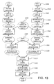
- the stereo reconstruction is performed by triangulating the corresponding pair of image defined points using known techniques. This is shown in steps 1100, 1110, 1120 in Fig. 13 . However, only image correspondences that are known to be good are passed in as input, and the association between reconstructed 3D points (in stereo tracker coordinates) and 3D model points is passed through this step.
- the output of lookup matching (step 1110) provides a 1:1 association between a set of pixel locations in the left image and a set of pixels in the right image.
- each left/right pair of pixel locations are triangulated to generate an estimate of the 3D location of that feature in the scene.
- Each of these 3D coordinates are determined in a coordinate system fixed to the stereo tracking system (e.g., the left camera or right camera location, or the center between the cameras, can be used to define the origin and axes of the coordinate system).
- the 3D model points are defined in a model-centric coordinate system (e.g., the cone axis is the z axis, the center of the small end is (0,0,0).)
- Absolute orientation determines the transform between these two coordinate systems (tracker-centric and model-centric).
- step 1130 Once at least three correspondences between specific 3D tracker points (i.e., points in the tracker-centric coordinate system) and specific 3D model points (i.e., points in the model-centric coordinate system) are known (step 1130), conventional absolute orientation processes (step 1140) are used to determine the rigid-body transformation relating the tracker coordinate system to the model coordinate system, thereby determining the spatial location and orientation of the model in tracker coordinates (step 1150). As such, the pose of the tile 400 and the tracking patterns 210, 308 are tied to the model. The data is then used by the system to depict the actual movement of the oral fixture and tool fixture as movement of the associated models relative to scanned representation of the area of interest (e.g. the prior scanned image of the oral cavity).
- the processes for forming the oral fixture 12, for scanning the location of fiducials on the fixture 12, and for registering the prior scanned image to actual video image are described in detail in US Patent Application No. 14/209,500 .
- the bracket assembly 100 is attached to the flanges 28, 30 on the oral fixture 12 and to the fixture tracking assembly 200.
- the oral fixture 12 is attached to the appropriate teeth of the patient.
- the present invention uses two external cameras 800 mounted in a location to view the fixture tracking pattern 210 and tool tracking pattern 308 and detect the defined points as described above.
- the data from the cameras 800 is transmitted to a processor 810 which conducts some or all of the processing described above and illustrated into Fig. 13 . From that the system determines the position (pose) of the tracking patterns and their movement within a predetermined coordinate system.
- the system uses the location of the fiducial markers on the oral fixture 12 from the scanned image and their relationship to the fixture tracking assembly 200 for determining movement of the patient and the location of the tool fixture assembly 300 relative to the oral fixture 12, and then to calculate the location of the tool bit tip relative to the operation site.
- the present invention provides significant advantages over the prior existing stereo tracking systems.
- the present invention preferably implements a significant number of computationally-expensive steps on each camera independently of the other cameras and the main processing system. This allows for easier scaling of the system, especially as the number of cameras in the system grows beyond two.
- the requirement of feature correspondence would grow as a function of O(Nc 2 ) where Nc is the number of cameras used in a standard stereo tracking system.
- processing could be carried out in a processor in the camera and the programming and data could be embedded in memory associated with the processor.
- tile as a uniquely-identifiable unit, which can be arranged to form an optical pattern
- the term is not restricted to the conventional notion of "tiling" of such units as abutting and nonoverlapping.
- Co-pending Application Serial No. 14/209,500 details an interleaved encoding scheme where multiple tiles overlap and occupy the same portion of a pattern in order to enhance two-scale detection. It is contemplated that even in a conventionally-tiled pattern, the arrangement of the unique tiles can be chosen such that each junction of 4 tiles forms another unique tile from the combination of portions of the tiles that are nearest the junction, in such a way that every patch on the pattern is a member of 2 or more tiles.
- tile boundaries with 90-degree corners it is further contemplated that the tile boundaries can contain arbitrary polyline or rounded segments.
- the two-scale encoding scheme in co-pending Application Serial No. 14/209,500 includes a combination of square tiles and complex tiles that have holes.
- surgical instrument or “surgical tool” is intended to cover other tools used during intraoral procedures, such as ablation tools for ablating tissue, including third molars in children.
- the system or systems described herein may be implemented on any form of computer or computers and the components may be implemented as dedicated applications or in client-server architectures, including a web-based architecture, and can include functional programs, codes, and code segments.
- the system of the present invention may include a software program be stored on a computer and/or storage device (e.g., mediums), and/or may be executed through a network.
- the method may be implemented through program code or program modules stored on a storage medium.
- the embodiments herein may be described in terms of various processing steps. Such processing steps may be realized by any number of hardware and/or software components that perform the specified functions.
- the described embodiments may employ various integrated circuit components, e.g., memory elements, processing elements, logic elements, look-up tables, and the like, which may carry out a variety of functions under the control of one or more microprocessors or other control devices.
- the elements of the described embodiments are implemented using software programming or software elements the invention may be implemented with any programming or scripting language such as C, C++, Java, assembler, or the like, with the various algorithms being implemented with any combination of data structures, objects, processes, routines or other programming elements.
- Functional aspects may be implemented in algorithms that execute on one or more processors.
- the embodiments of the invention could employ any number of conventional techniques for electronics configuration, signal processing and/or control, data processing and the like.
- the words “mechanism” and “element” are used broadly and are not limited to mechanical or physical embodiments, but can include software routines in conjunction with processors, etc.
Landscapes
- Health & Medical Sciences (AREA)
- Life Sciences & Earth Sciences (AREA)
- Surgery (AREA)
- Animal Behavior & Ethology (AREA)
- Veterinary Medicine (AREA)
- Public Health (AREA)
- General Health & Medical Sciences (AREA)
- Engineering & Computer Science (AREA)
- Oral & Maxillofacial Surgery (AREA)
- Medical Informatics (AREA)
- Biomedical Technology (AREA)
- Heart & Thoracic Surgery (AREA)
- Molecular Biology (AREA)
- Nuclear Medicine, Radiotherapy & Molecular Imaging (AREA)
- Dentistry (AREA)
- Pathology (AREA)
- Epidemiology (AREA)
- Robotics (AREA)
- Physics & Mathematics (AREA)
- Biophysics (AREA)
- High Energy & Nuclear Physics (AREA)
- Optics & Photonics (AREA)
- Radiology & Medical Imaging (AREA)
- Dental Tools And Instruments Or Auxiliary Dental Instruments (AREA)
- Image Processing (AREA)
Applications Claiming Priority (1)
| Application Number | Priority Date | Filing Date | Title |
|---|---|---|---|
| US14/487,987 US9402691B2 (en) | 2014-09-16 | 2014-09-16 | System for determining and tracking movement during a medical procedure |
Publications (3)
| Publication Number | Publication Date |
|---|---|
| EP2997927A2 true EP2997927A2 (fr) | 2016-03-23 |
| EP2997927A3 EP2997927A3 (fr) | 2016-08-31 |
| EP2997927B1 EP2997927B1 (fr) | 2018-11-07 |
Family
ID=54196771
Family Applications (1)
| Application Number | Title | Priority Date | Filing Date |
|---|---|---|---|
| EP15185062.5A Active EP2997927B1 (fr) | 2014-09-16 | 2015-09-14 | Système de détermination et de suivi de mouvement au cours d'une procédure médicale |
Country Status (6)
| Country | Link |
|---|---|
| US (1) | US9402691B2 (fr) |
| EP (1) | EP2997927B1 (fr) |
| KR (1) | KR101776062B1 (fr) |
| CN (1) | CN105411678B (fr) |
| DK (1) | DK2997927T3 (fr) |
| ES (1) | ES2708555T3 (fr) |
Cited By (1)
| Publication number | Priority date | Publication date | Assignee | Title |
|---|---|---|---|---|
| EP4119087A4 (fr) * | 2020-04-13 | 2023-11-15 | Jedicare Medical Co., Ltd. | Marqueur optique pour positionner un instrument médical, et ensemble instrument médical |
Families Citing this family (31)
| Publication number | Priority date | Publication date | Assignee | Title |
|---|---|---|---|---|
| EP2429444B1 (fr) | 2009-05-11 | 2024-02-28 | TriAgenics, Inc. | Ablation thérapeutique de bourgeon dentaire |
| WO2014143014A1 (fr) | 2013-03-15 | 2014-09-18 | Triagenics, Llc | Ablation thérapeutique de bourgeon dentaire |
| US10022202B2 (en) | 2013-03-15 | 2018-07-17 | Triagenics, Llc | Therapeutic tooth bud ablation |
| USD776813S1 (en) * | 2014-09-16 | 2017-01-17 | X-Nav Technologies, LLC | Tracking pattern holder |
| USD779062S1 (en) * | 2015-09-14 | 2017-02-14 | X-Nav Technologies, LLC | Tracking pattern holder for a surgical tool |
| US11278355B2 (en) * | 2015-10-14 | 2022-03-22 | Ecential Robotics | Modular fluoro-navigation instrument |
| WO2017117369A1 (fr) | 2015-12-31 | 2017-07-06 | Stryker Corporation | Système et procédés pour réaliser une intervention chirurgicale sur un patient au niveau d'un site cible défini par un objet virtuel |
| MX2018011794A (es) | 2016-03-31 | 2019-02-13 | A Lee Ernesto | Método, dispositivos y artículos para la conducción de aumento de injerto estético de hueso de mandibula mínimamente invasivo subperióstico. |
| EP3439558B1 (fr) * | 2016-04-06 | 2021-06-02 | X-Nav Technologies, LLC | Système pour permettre une poursuite sans repère de trace de sonde |
| WO2017205351A1 (fr) | 2016-05-23 | 2017-11-30 | Mako Surgical Corp. | Systèmes et procédés d'identification et de suivi d'objets physiques pendant une intervention chirurgicale robotisée |
| US10016242B2 (en) * | 2016-06-06 | 2018-07-10 | Neocis Inc. | Splint device for forming a fiducial marker for a surgical robot guidance system, and associated method |
| KR101820682B1 (ko) * | 2016-08-09 | 2018-01-23 | 주식회사 고영테크놀러지 | 옵티컬 트래킹용 마커, 옵티컬 트래킹 시스템 및 옵티컬 트래킹 방법 |
| US11259894B2 (en) * | 2016-09-19 | 2022-03-01 | Neocis, Inc. | Tracking and guidance arrangement for a surgical robot system and related method |
| ES2683085B2 (es) * | 2017-02-24 | 2019-04-25 | Dmr Dental S L | Procedimiento de escaneo de un rostro humano para una alineacion entre el rostro y los dientes de una persona y conjunto de marcadores para su ejecucion |
| TWI783995B (zh) * | 2017-04-28 | 2022-11-21 | 美商尼奧西斯股份有限公司 | 進行導引口腔顎面程序方法及相關系統 |
| WO2019014759A1 (fr) | 2017-07-18 | 2019-01-24 | Claronav Inc. | Alignement sur la base de la surface d'une mâchoire |
| US10736714B1 (en) | 2017-11-06 | 2020-08-11 | Charles Maupin | Computer-guided endodontic procedure |
| WO2019140533A1 (fr) | 2018-01-22 | 2019-07-25 | Claronav Inc. | Instrument chirurgical robotisé |
| US11523753B2 (en) | 2018-02-07 | 2022-12-13 | Claronav Inc. | Head tracking frame for dental navigation |
| US11771537B2 (en) * | 2018-09-27 | 2023-10-03 | X-Nav Technologies, LLC | MElHOD for dynamically guiding a dental oral and maxillofacial prosthesis |
| EP3897482A1 (fr) * | 2018-12-20 | 2021-10-27 | Coloplast A/S | Classification d'affections de stomies avec transformation de données d'image, dispositifs et procédés associés |
| FR3094627B1 (fr) * | 2019-04-04 | 2022-09-02 | Quantum Surgical | Dispositif de guidage d’une aiguille médicale |
| EP3979938A4 (fr) | 2019-06-06 | 2023-06-28 | TriAgenics, Inc. | Systèmes de sonde d'ablation |
| WO2021016476A1 (fr) * | 2019-07-24 | 2021-01-28 | Radtec Medical Devices, Inc. | Procédés et appareils pour l'alignement de repères de dispositifs de positionnement intrabuccal pour la radiothérapie de cancer de la tête et du cou |
| US20210153959A1 (en) * | 2019-11-26 | 2021-05-27 | Intuitive Surgical Operations, Inc. | Physical medical element affixation systems, methods, and materials |
| US11369455B2 (en) | 2020-01-13 | 2022-06-28 | Image Navigation Ltd. | Stable affixation system for guided dental implantation |
| US10966799B1 (en) | 2020-01-13 | 2021-04-06 | Image Navigation Ltd. | Stable affixation system for guided dental implantation |
| US11559373B2 (en) | 2020-01-13 | 2023-01-24 | Image Navigation Ltd. | Stable winged affixation system for guided dental implantation |
| CN111388087A (zh) * | 2020-04-26 | 2020-07-10 | 深圳市鑫君特智能医疗器械有限公司 | 手术导航系统及执行手术导航方法的计算机与存储介质 |
| US10949986B1 (en) * | 2020-05-12 | 2021-03-16 | Proprio, Inc. | Methods and systems for imaging a scene, such as a medical scene, and tracking objects within the scene |
| US20220104885A1 (en) * | 2020-10-06 | 2022-04-07 | Michael J. Hartman | Patient specific dynamic navigation tracker arm mount apparatus and method |
Family Cites Families (51)
| Publication number | Priority date | Publication date | Assignee | Title |
|---|---|---|---|---|
| US3878610A (en) | 1973-11-19 | 1975-04-22 | William Alfred Coscina | Low profile dental impression tray and set of such trays |
| CA2260688A1 (fr) | 1989-11-21 | 1991-05-21 | I.S.G. Technologies, Inc. | Visionnement d'une image anatomique correle par sonde |
| GB9015594D0 (en) | 1990-07-16 | 1991-04-24 | Plessey Roke Manor Res | Tracking arrangements and systems |
| US5823958A (en) | 1990-11-26 | 1998-10-20 | Truppe; Michael | System and method for displaying a structural data image in real-time correlation with moveable body |
| US6096048A (en) | 1994-04-20 | 2000-08-01 | Howard, Iii; Matthew A. | Noninvasive, reattachable skull fiducial marker system |
| US5588430A (en) | 1995-02-14 | 1996-12-31 | University Of Florida Research Foundation, Inc. | Repeat fixation for frameless stereotactic procedure |
| US5772432A (en) | 1996-10-18 | 1998-06-30 | Minnesota Mining & Manufacturing Co. | Dental impression tray with improved adhesion to impression material |
| JP3512992B2 (ja) | 1997-01-07 | 2004-03-31 | 株式会社東芝 | 画像処理装置および画像処理方法 |
| JP2927350B2 (ja) | 1997-03-27 | 1999-07-28 | 株式会社モノリス | 多重解像度フィルタ処理方法およびその方法を利用することのできる画像マッチング方法 |
| DE19715202B4 (de) | 1997-04-11 | 2006-02-02 | Brainlab Ag | Referenzierungsvorrichtung mit einem Mundstück |
| JP4612194B2 (ja) | 1998-12-23 | 2011-01-12 | イメージ・ガイディッド・テクノロジーズ・インコーポレイテッド | 複数センサーによって追跡されるハイブリッド3dプローブ |
| DE19902273A1 (de) | 1999-01-21 | 2000-08-03 | Dieter Edinger | Vorrichtung zur Bestimmung einer Plazierung von Dental-Implantaten im Kieferknochen |
| US6206891B1 (en) | 1999-09-14 | 2001-03-27 | Medeye Medical Technology Ltd. | Device and method for calibration of a stereotactic localization system |
| US6368285B1 (en) | 1999-09-21 | 2002-04-09 | Biosense, Inc. | Method and apparatus for mapping a chamber of a heart |
| EP1219260B1 (fr) | 2000-12-19 | 2003-06-25 | BrainLAB AG | Procédé et dispositif de traitement dentaire assisté par un système de navigation |
| EP1401323A4 (fr) | 2001-05-31 | 2009-06-03 | Image Navigation Ltd | Procedes d'implantologie guidee par imagerie |
| US20030156681A1 (en) | 2002-02-15 | 2003-08-21 | Egidio Cianciosi | Dental imaging system and apparatus using IEEE 1394 protocol |
| US6978167B2 (en) | 2002-07-01 | 2005-12-20 | Claron Technology Inc. | Video pose tracking system and method |
| CN2565417Y (zh) * | 2002-08-15 | 2003-08-13 | 北京大学 | 用于手术导航的红外无线指示跟踪装置 |
| US7166114B2 (en) | 2002-09-18 | 2007-01-23 | Stryker Leibinger Gmbh & Co Kg | Method and system for calibrating a surgical tool and adapter thereof |
| CN1193714C (zh) * | 2002-09-23 | 2005-03-23 | 陈慧军 | 人体靶向微创定位导航床架及利用其实现体外定位的方法 |
| US20040068263A1 (en) | 2002-10-04 | 2004-04-08 | Benoit Chouinard | CAS bone reference with articulated support |
| US7835778B2 (en) | 2003-10-16 | 2010-11-16 | Medtronic Navigation, Inc. | Method and apparatus for surgical navigation of a multiple piece construct for implantation |
| US7330577B2 (en) | 2004-01-27 | 2008-02-12 | Densys Ltd. | Three-dimensional modeling of the oral cavity by projecting a two-dimensional array of random patterns |
| KR101235320B1 (ko) | 2004-09-14 | 2013-02-21 | 오라티오 비.브이. | 미적인 임플란트 어버트먼트를 가지는 세라믹 치아임플란트의 제조방법 및 설치방법 |
| US8376738B2 (en) | 2004-10-20 | 2013-02-19 | Big Jaw Bone, Llc | Universal impression trays and method of use |
| US7894878B2 (en) | 2004-12-30 | 2011-02-22 | Board Of Regents, The University Of Texas System | Anatomically-referenced fiducial marker for registration of data |
| WO2006094156A2 (fr) | 2005-03-02 | 2006-09-08 | Calypso Medical Technologies, Inc. | Systemes et procedes de traitement d'un patient par intervention chirurgicale ou radiotherapie guidee |
| US8172573B2 (en) | 2005-04-18 | 2012-05-08 | Image Navigation Ltd | Methods and apparatus for dental implantation |
| US8215957B2 (en) | 2005-05-12 | 2012-07-10 | Robert Shelton | Dental implant placement locator and method of use |
| US7889905B2 (en) | 2005-05-23 | 2011-02-15 | The Penn State Research Foundation | Fast 3D-2D image registration method with application to continuously guided endoscopy |
| US9498647B2 (en) | 2005-09-23 | 2016-11-22 | Allen B. Kantrowitz | Fiducial marker system for subject movement compensation during medical treatment |
| US7599538B2 (en) | 2006-07-24 | 2009-10-06 | Apteryx, Inc. | Method and system for automatic intra-oral sensor locating for image acquisition |
| US8565853B2 (en) | 2006-08-11 | 2013-10-22 | DePuy Synthes Products, LLC | Simulated bone or tissue manipulation |
| WO2008051129A1 (fr) | 2006-10-27 | 2008-05-02 | Nobel Biocare Services Ag | Porte-empreinte dentaire permettant d'obtenir une empreinte d'une structure dentaire |
| US10206757B2 (en) | 2007-01-10 | 2019-02-19 | Nobel Biocare Services Ag | Method and system for dental planning and production |
| US8218905B2 (en) | 2007-10-12 | 2012-07-10 | Claron Technology Inc. | Method, system and software product for providing efficient registration of 3D image data |
| WO2009055379A1 (fr) | 2007-10-22 | 2009-04-30 | The Methodist Hospital System | Systèmes, procédés et appareils d'enregistrement de l'orientation et de la position du corps |
| US20090306499A1 (en) | 2008-06-09 | 2009-12-10 | Mako Surgical Corp. | Self-detecting kinematic clamp assembly |
| TWI535424B (zh) | 2009-03-13 | 2016-06-01 | 神農資訊股份有限公司 | 植牙手術模板製造系統及方法 |
| US9226801B2 (en) | 2010-03-08 | 2016-01-05 | Ibur, Llc | Custom linkable imaging and multifunctional tray |
| US8435033B2 (en) * | 2010-07-19 | 2013-05-07 | Rainbow Medical Ltd. | Dental navigation techniques |
| US20120316486A1 (en) | 2010-08-20 | 2012-12-13 | Andrew Cheung | Surgical Component Navigation Systems And Methods |
| US20120046536A1 (en) | 2010-08-20 | 2012-02-23 | Manhattan Technologies, Llc | Surgical Instrument Navigation Systems and Methods |
| WO2012068679A1 (fr) | 2010-11-23 | 2012-05-31 | Claron Technology Inc. | Procédé et appareil pour enregistrement automatisé et suivi des poses |
| US8750590B2 (en) | 2011-02-03 | 2014-06-10 | Greenberg Surgical Technologies, Llc | Removable handle scan body for impression trays and radiographic templates for integrated optical and CT scanning |
| AU2012319093A1 (en) * | 2011-06-27 | 2014-01-16 | Board Of Regents Of The University Of Nebraska | On-board tool tracking system and methods of computer assisted surgery |
| US8938282B2 (en) | 2011-10-28 | 2015-01-20 | Navigate Surgical Technologies, Inc. | Surgical location monitoring system and method with automatic registration |
| TWI504383B (zh) | 2012-11-27 | 2015-10-21 | Nat Univ Chung Cheng | Computer - aided positioning guidance system for dental implants |
| CA2893786C (fr) * | 2012-12-07 | 2021-01-05 | University Of Houston | Systemes et procedes de gestion d'une procedure chirurgicale |
| US10743940B2 (en) | 2013-10-02 | 2020-08-18 | Mininavident Ag | Navigation system and method for dental and cranio-maxillofacial surgery, positioning tool and method of positioning a marker member |
-
2014
- 2014-09-16 US US14/487,987 patent/US9402691B2/en active Active
-
2015
- 2015-09-14 DK DK15185062.5T patent/DK2997927T3/en active
- 2015-09-14 ES ES15185062T patent/ES2708555T3/es active Active
- 2015-09-14 EP EP15185062.5A patent/EP2997927B1/fr active Active
- 2015-09-16 KR KR1020150130809A patent/KR101776062B1/ko active IP Right Grant
- 2015-09-16 CN CN201510591924.8A patent/CN105411678B/zh active Active
Non-Patent Citations (1)
| Title |
|---|
| None |
Cited By (1)
| Publication number | Priority date | Publication date | Assignee | Title |
|---|---|---|---|---|
| EP4119087A4 (fr) * | 2020-04-13 | 2023-11-15 | Jedicare Medical Co., Ltd. | Marqueur optique pour positionner un instrument médical, et ensemble instrument médical |
Also Published As
| Publication number | Publication date |
|---|---|
| CN105411678B (zh) | 2018-02-02 |
| US20160074129A1 (en) | 2016-03-17 |
| US9402691B2 (en) | 2016-08-02 |
| EP2997927A3 (fr) | 2016-08-31 |
| CN105411678A (zh) | 2016-03-23 |
| EP2997927B1 (fr) | 2018-11-07 |
| KR20160032694A (ko) | 2016-03-24 |
| DK2997927T3 (en) | 2019-02-18 |
| ES2708555T3 (es) | 2019-04-10 |
| KR101776062B1 (ko) | 2017-09-07 |
Similar Documents
| Publication | Publication Date | Title |
|---|---|---|
| EP2997927B1 (fr) | Système de détermination et de suivi de mouvement au cours d'une procédure médicale | |
| EP2998931B1 (fr) | Système de guidage par image pour détecter et suivre une pose d'image | |
| US9844324B2 (en) | Image guided navigation system | |
| US9125624B2 (en) | Method and apparatus for automated registration and pose tracking | |
| EP3439558B1 (fr) | Système pour permettre une poursuite sans repère de trace de sonde | |
| US20110098553A1 (en) | Automatic registration of images for image guided surgery | |
| WO2018152742A1 (fr) | Surfaces multiples pour alignement physique-à-image/image-à-physique et vérification d'image | |
| US20230355367A1 (en) | Method for dynamically guiding a dental oral and maxillofacial prosthesis using a 3d dataset | |
| US20210205022A1 (en) | Reference device for real-time tracking of bone and/or surgical objects in computer-assisted surgery | |
| TWI381825B (zh) | 影像之區域分析方法 | |
| WO2020084616A1 (fr) | Procédé et appareil de vérification de guide chirurgical dentaire | |
| US20240122654A1 (en) | Device for use in computer-aided surgery | |
| KR20240063296A (ko) | 임플란트 시술을 위한 모션 추적 시스템 | |
| CN113470168A (zh) | 基于增强现实的多维度颌骨虚实配准误差检测装置及方法 |
Legal Events
| Date | Code | Title | Description |
|---|---|---|---|
| PUAI | Public reference made under article 153(3) epc to a published international application that has entered the european phase |
Free format text: ORIGINAL CODE: 0009012 |
|
| AK | Designated contracting states |
Kind code of ref document: A2 Designated state(s): AL AT BE BG CH CY CZ DE DK EE ES FI FR GB GR HR HU IE IS IT LI LT LU LV MC MK MT NL NO PL PT RO RS SE SI SK SM TR |
|
| AX | Request for extension of the european patent |
Extension state: BA ME |
|
| RIC1 | Information provided on ipc code assigned before grant |
Ipc: A61B 90/00 20160101ALI20160226BHEP Ipc: A61B 34/20 20160101ALI20160226BHEP Ipc: A61B 90/57 20160101AFI20160226BHEP |
|
| PUAL | Search report despatched |
Free format text: ORIGINAL CODE: 0009013 |
|
| AK | Designated contracting states |
Kind code of ref document: A3 Designated state(s): AL AT BE BG CH CY CZ DE DK EE ES FI FR GB GR HR HU IE IS IT LI LT LU LV MC MK MT NL NO PL PT RO RS SE SI SK SM TR |
|
| AX | Request for extension of the european patent |
Extension state: BA ME |
|
| RIC1 | Information provided on ipc code assigned before grant |
Ipc: A61B 90/57 20160101AFI20160727BHEP Ipc: A61B 90/00 20160101ALI20160727BHEP Ipc: A61B 34/20 20160101ALI20160727BHEP |
|
| STAA | Information on the status of an ep patent application or granted ep patent |
Free format text: STATUS: REQUEST FOR EXAMINATION WAS MADE |
|
| 17P | Request for examination filed |
Effective date: 20170227 |
|
| RBV | Designated contracting states (corrected) |
Designated state(s): AL AT BE BG CH CY CZ DE DK EE ES FI FR GB GR HR HU IE IS IT LI LT LU LV MC MK MT NL NO PL PT RO RS SE SI SK SM TR |
|
| GRAP | Despatch of communication of intention to grant a patent |
Free format text: ORIGINAL CODE: EPIDOSNIGR1 |
|
| STAA | Information on the status of an ep patent application or granted ep patent |
Free format text: STATUS: GRANT OF PATENT IS INTENDED |
|
| INTG | Intention to grant announced |
Effective date: 20171107 |
|
| RIN1 | Information on inventor provided before grant (corrected) |
Inventor name: MERITT, SCOTT A. Inventor name: EMERY, ROBERT W. Inventor name: SCHARFF, CHRISTOPHER W. Inventor name: MARANDOLA, EDWARD J |
|
| GRAJ | Information related to disapproval of communication of intention to grant by the applicant or resumption of examination proceedings by the epo deleted |
Free format text: ORIGINAL CODE: EPIDOSDIGR1 |
|
| STAA | Information on the status of an ep patent application or granted ep patent |
Free format text: STATUS: REQUEST FOR EXAMINATION WAS MADE |
|
| INTC | Intention to grant announced (deleted) | ||
| GRAP | Despatch of communication of intention to grant a patent |
Free format text: ORIGINAL CODE: EPIDOSNIGR1 |
|
| STAA | Information on the status of an ep patent application or granted ep patent |
Free format text: STATUS: GRANT OF PATENT IS INTENDED |
|
| INTG | Intention to grant announced |
Effective date: 20180503 |
|
| GRAS | Grant fee paid |
Free format text: ORIGINAL CODE: EPIDOSNIGR3 |
|
| GRAA | (expected) grant |
Free format text: ORIGINAL CODE: 0009210 |
|
| STAA | Information on the status of an ep patent application or granted ep patent |
Free format text: STATUS: THE PATENT HAS BEEN GRANTED |
|
| AK | Designated contracting states |
Kind code of ref document: B1 Designated state(s): AL AT BE BG CH CY CZ DE DK EE ES FI FR GB GR HR HU IE IS IT LI LT LU LV MC MK MT NL NO PL PT RO RS SE SI SK SM TR |
|
| REG | Reference to a national code |
Ref country code: GB Ref legal event code: FG4D |
|
| REG | Reference to a national code |
Ref country code: CH Ref legal event code: EP Ref country code: AT Ref legal event code: REF Ref document number: 1061181 Country of ref document: AT Kind code of ref document: T Effective date: 20181115 |
|
| REG | Reference to a national code |
Ref country code: DE Ref legal event code: R096 Ref document number: 602015019405 Country of ref document: DE |
|
| REG | Reference to a national code |
Ref country code: IE Ref legal event code: FG4D |
|
| REG | Reference to a national code |
Ref country code: CH Ref legal event code: NV Representative=s name: MURGITROYD AND COMPANY, CH |
|
| REG | Reference to a national code |
Ref country code: DK Ref legal event code: T3 Effective date: 20190211 |
|
| REG | Reference to a national code |
Ref country code: NL Ref legal event code: FP |
|
| REG | Reference to a national code |
Ref country code: LT Ref legal event code: MG4D |
|
| REG | Reference to a national code |
Ref country code: ES Ref legal event code: FG2A Ref document number: 2708555 Country of ref document: ES Kind code of ref document: T3 Effective date: 20190410 |
|
| REG | Reference to a national code |
Ref country code: AT Ref legal event code: MK05 Ref document number: 1061181 Country of ref document: AT Kind code of ref document: T Effective date: 20181107 |
|
| PG25 | Lapsed in a contracting state [announced via postgrant information from national office to epo] |
Ref country code: BG Free format text: LAPSE BECAUSE OF FAILURE TO SUBMIT A TRANSLATION OF THE DESCRIPTION OR TO PAY THE FEE WITHIN THE PRESCRIBED TIME-LIMIT Effective date: 20190207 Ref country code: HR Free format text: LAPSE BECAUSE OF FAILURE TO SUBMIT A TRANSLATION OF THE DESCRIPTION OR TO PAY THE FEE WITHIN THE PRESCRIBED TIME-LIMIT Effective date: 20181107 Ref country code: LT Free format text: LAPSE BECAUSE OF FAILURE TO SUBMIT A TRANSLATION OF THE DESCRIPTION OR TO PAY THE FEE WITHIN THE PRESCRIBED TIME-LIMIT Effective date: 20181107 Ref country code: LV Free format text: LAPSE BECAUSE OF FAILURE TO SUBMIT A TRANSLATION OF THE DESCRIPTION OR TO PAY THE FEE WITHIN THE PRESCRIBED TIME-LIMIT Effective date: 20181107 Ref country code: NO Free format text: LAPSE BECAUSE OF FAILURE TO SUBMIT A TRANSLATION OF THE DESCRIPTION OR TO PAY THE FEE WITHIN THE PRESCRIBED TIME-LIMIT Effective date: 20190207 Ref country code: IS Free format text: LAPSE BECAUSE OF FAILURE TO SUBMIT A TRANSLATION OF THE DESCRIPTION OR TO PAY THE FEE WITHIN THE PRESCRIBED TIME-LIMIT Effective date: 20190307 Ref country code: FI Free format text: LAPSE BECAUSE OF FAILURE TO SUBMIT A TRANSLATION OF THE DESCRIPTION OR TO PAY THE FEE WITHIN THE PRESCRIBED TIME-LIMIT Effective date: 20181107 Ref country code: AT Free format text: LAPSE BECAUSE OF FAILURE TO SUBMIT A TRANSLATION OF THE DESCRIPTION OR TO PAY THE FEE WITHIN THE PRESCRIBED TIME-LIMIT Effective date: 20181107 |
|
| PG25 | Lapsed in a contracting state [announced via postgrant information from national office to epo] |
Ref country code: AL Free format text: LAPSE BECAUSE OF FAILURE TO SUBMIT A TRANSLATION OF THE DESCRIPTION OR TO PAY THE FEE WITHIN THE PRESCRIBED TIME-LIMIT Effective date: 20181107 Ref country code: PT Free format text: LAPSE BECAUSE OF FAILURE TO SUBMIT A TRANSLATION OF THE DESCRIPTION OR TO PAY THE FEE WITHIN THE PRESCRIBED TIME-LIMIT Effective date: 20190307 Ref country code: SE Free format text: LAPSE BECAUSE OF FAILURE TO SUBMIT A TRANSLATION OF THE DESCRIPTION OR TO PAY THE FEE WITHIN THE PRESCRIBED TIME-LIMIT Effective date: 20181107 Ref country code: RS Free format text: LAPSE BECAUSE OF FAILURE TO SUBMIT A TRANSLATION OF THE DESCRIPTION OR TO PAY THE FEE WITHIN THE PRESCRIBED TIME-LIMIT Effective date: 20181107 Ref country code: GR Free format text: LAPSE BECAUSE OF FAILURE TO SUBMIT A TRANSLATION OF THE DESCRIPTION OR TO PAY THE FEE WITHIN THE PRESCRIBED TIME-LIMIT Effective date: 20190208 |
|
| PG25 | Lapsed in a contracting state [announced via postgrant information from national office to epo] |
Ref country code: CZ Free format text: LAPSE BECAUSE OF FAILURE TO SUBMIT A TRANSLATION OF THE DESCRIPTION OR TO PAY THE FEE WITHIN THE PRESCRIBED TIME-LIMIT Effective date: 20181107 Ref country code: PL Free format text: LAPSE BECAUSE OF FAILURE TO SUBMIT A TRANSLATION OF THE DESCRIPTION OR TO PAY THE FEE WITHIN THE PRESCRIBED TIME-LIMIT Effective date: 20181107 |
|
| REG | Reference to a national code |
Ref country code: DE Ref legal event code: R097 Ref document number: 602015019405 Country of ref document: DE |
|
| PG25 | Lapsed in a contracting state [announced via postgrant information from national office to epo] |
Ref country code: SK Free format text: LAPSE BECAUSE OF FAILURE TO SUBMIT A TRANSLATION OF THE DESCRIPTION OR TO PAY THE FEE WITHIN THE PRESCRIBED TIME-LIMIT Effective date: 20181107 Ref country code: RO Free format text: LAPSE BECAUSE OF FAILURE TO SUBMIT A TRANSLATION OF THE DESCRIPTION OR TO PAY THE FEE WITHIN THE PRESCRIBED TIME-LIMIT Effective date: 20181107 Ref country code: EE Free format text: LAPSE BECAUSE OF FAILURE TO SUBMIT A TRANSLATION OF THE DESCRIPTION OR TO PAY THE FEE WITHIN THE PRESCRIBED TIME-LIMIT Effective date: 20181107 Ref country code: SM Free format text: LAPSE BECAUSE OF FAILURE TO SUBMIT A TRANSLATION OF THE DESCRIPTION OR TO PAY THE FEE WITHIN THE PRESCRIBED TIME-LIMIT Effective date: 20181107 |
|
| PLBE | No opposition filed within time limit |
Free format text: ORIGINAL CODE: 0009261 |
|
| STAA | Information on the status of an ep patent application or granted ep patent |
Free format text: STATUS: NO OPPOSITION FILED WITHIN TIME LIMIT |
|
| 26N | No opposition filed |
Effective date: 20190808 |
|
| PG25 | Lapsed in a contracting state [announced via postgrant information from national office to epo] |
Ref country code: SI Free format text: LAPSE BECAUSE OF FAILURE TO SUBMIT A TRANSLATION OF THE DESCRIPTION OR TO PAY THE FEE WITHIN THE PRESCRIBED TIME-LIMIT Effective date: 20181107 |
|
| PG25 | Lapsed in a contracting state [announced via postgrant information from national office to epo] |
Ref country code: TR Free format text: LAPSE BECAUSE OF FAILURE TO SUBMIT A TRANSLATION OF THE DESCRIPTION OR TO PAY THE FEE WITHIN THE PRESCRIBED TIME-LIMIT Effective date: 20181107 |
|
| PG25 | Lapsed in a contracting state [announced via postgrant information from national office to epo] |
Ref country code: MC Free format text: LAPSE BECAUSE OF FAILURE TO SUBMIT A TRANSLATION OF THE DESCRIPTION OR TO PAY THE FEE WITHIN THE PRESCRIBED TIME-LIMIT Effective date: 20181107 |
|
| PG25 | Lapsed in a contracting state [announced via postgrant information from national office to epo] |
Ref country code: IE Free format text: LAPSE BECAUSE OF NON-PAYMENT OF DUE FEES Effective date: 20190914 Ref country code: LU Free format text: LAPSE BECAUSE OF NON-PAYMENT OF DUE FEES Effective date: 20190914 |
|
| PG25 | Lapsed in a contracting state [announced via postgrant information from national office to epo] |
Ref country code: CY Free format text: LAPSE BECAUSE OF FAILURE TO SUBMIT A TRANSLATION OF THE DESCRIPTION OR TO PAY THE FEE WITHIN THE PRESCRIBED TIME-LIMIT Effective date: 20181107 |
|
| PG25 | Lapsed in a contracting state [announced via postgrant information from national office to epo] |
Ref country code: MT Free format text: LAPSE BECAUSE OF FAILURE TO SUBMIT A TRANSLATION OF THE DESCRIPTION OR TO PAY THE FEE WITHIN THE PRESCRIBED TIME-LIMIT Effective date: 20181107 Ref country code: HU Free format text: LAPSE BECAUSE OF FAILURE TO SUBMIT A TRANSLATION OF THE DESCRIPTION OR TO PAY THE FEE WITHIN THE PRESCRIBED TIME-LIMIT; INVALID AB INITIO Effective date: 20150914 |
|
| PG25 | Lapsed in a contracting state [announced via postgrant information from national office to epo] |
Ref country code: MK Free format text: LAPSE BECAUSE OF FAILURE TO SUBMIT A TRANSLATION OF THE DESCRIPTION OR TO PAY THE FEE WITHIN THE PRESCRIBED TIME-LIMIT Effective date: 20181107 |
|
| PGFP | Annual fee paid to national office [announced via postgrant information from national office to epo] |
Ref country code: DK Payment date: 20230627 Year of fee payment: 9 |
|
| PGFP | Annual fee paid to national office [announced via postgrant information from national office to epo] |
Ref country code: NL Payment date: 20230719 Year of fee payment: 9 |
|
| PGFP | Annual fee paid to national office [announced via postgrant information from national office to epo] |
Ref country code: IT Payment date: 20230810 Year of fee payment: 9 Ref country code: GB Payment date: 20230727 Year of fee payment: 9 |
|
| PGFP | Annual fee paid to national office [announced via postgrant information from national office to epo] |
Ref country code: FR Payment date: 20230710 Year of fee payment: 9 Ref country code: DE Payment date: 20230718 Year of fee payment: 9 Ref country code: BE Payment date: 20230818 Year of fee payment: 9 |
|
| PGFP | Annual fee paid to national office [announced via postgrant information from national office to epo] |
Ref country code: ES Payment date: 20231002 Year of fee payment: 9 |
|
| PGFP | Annual fee paid to national office [announced via postgrant information from national office to epo] |
Ref country code: CH Payment date: 20231001 Year of fee payment: 9 |