EP2997237B1 - Grundplatte zur montage und halterung rotierender maschinen und system mit dieser grundplatte - Google Patents
Grundplatte zur montage und halterung rotierender maschinen und system mit dieser grundplatte Download PDFInfo
- Publication number
- EP2997237B1 EP2997237B1 EP14725406.4A EP14725406A EP2997237B1 EP 2997237 B1 EP2997237 B1 EP 2997237B1 EP 14725406 A EP14725406 A EP 14725406A EP 2997237 B1 EP2997237 B1 EP 2997237B1
- Authority
- EP
- European Patent Office
- Prior art keywords
- baseplate
- load
- resisting member
- bending resisting
- gas turbine
- Prior art date
- Legal status (The legal status is an assumption and is not a legal conclusion. Google has not performed a legal analysis and makes no representation as to the accuracy of the status listed.)
- Active
Links
Images


Classifications
-
- F—MECHANICAL ENGINEERING; LIGHTING; HEATING; WEAPONS; BLASTING
- F01—MACHINES OR ENGINES IN GENERAL; ENGINE PLANTS IN GENERAL; STEAM ENGINES
- F01D—NON-POSITIVE DISPLACEMENT MACHINES OR ENGINES, e.g. STEAM TURBINES
- F01D25/00—Component parts, details, or accessories, not provided for in, or of interest apart from, other groups
- F01D25/28—Supporting or mounting arrangements, e.g. for turbine casing
-
- F—MECHANICAL ENGINEERING; LIGHTING; HEATING; WEAPONS; BLASTING
- F01—MACHINES OR ENGINES IN GENERAL; ENGINE PLANTS IN GENERAL; STEAM ENGINES
- F01D—NON-POSITIVE DISPLACEMENT MACHINES OR ENGINES, e.g. STEAM TURBINES
- F01D15/00—Adaptations of machines or engines for special use; Combinations of engines with devices driven thereby
- F01D15/08—Adaptations for driving, or combinations with, pumps
-
- F—MECHANICAL ENGINEERING; LIGHTING; HEATING; WEAPONS; BLASTING
- F01—MACHINES OR ENGINES IN GENERAL; ENGINE PLANTS IN GENERAL; STEAM ENGINES
- F01D—NON-POSITIVE DISPLACEMENT MACHINES OR ENGINES, e.g. STEAM TURBINES
- F01D15/00—Adaptations of machines or engines for special use; Combinations of engines with devices driven thereby
- F01D15/10—Adaptations for driving, or combinations with, electric generators
-
- F—MECHANICAL ENGINEERING; LIGHTING; HEATING; WEAPONS; BLASTING
- F16—ENGINEERING ELEMENTS AND UNITS; GENERAL MEASURES FOR PRODUCING AND MAINTAINING EFFECTIVE FUNCTIONING OF MACHINES OR INSTALLATIONS; THERMAL INSULATION IN GENERAL
- F16M—FRAMES, CASINGS OR BEDS OF ENGINES, MACHINES OR APPARATUS, NOT SPECIFIC TO ENGINES, MACHINES OR APPARATUS PROVIDED FOR ELSEWHERE; STANDS; SUPPORTS
- F16M1/00—Frames or casings of engines, machines or apparatus; Frames serving as machinery beds
- F16M1/04—Frames or casings of engines, machines or apparatus; Frames serving as machinery beds for rotary engines or similar machines
-
- F—MECHANICAL ENGINEERING; LIGHTING; HEATING; WEAPONS; BLASTING
- F16—ENGINEERING ELEMENTS AND UNITS; GENERAL MEASURES FOR PRODUCING AND MAINTAINING EFFECTIVE FUNCTIONING OF MACHINES OR INSTALLATIONS; THERMAL INSULATION IN GENERAL
- F16M—FRAMES, CASINGS OR BEDS OF ENGINES, MACHINES OR APPARATUS, NOT SPECIFIC TO ENGINES, MACHINES OR APPARATUS PROVIDED FOR ELSEWHERE; STANDS; SUPPORTS
- F16M5/00—Engine beds, i.e. means for supporting engines or machines on foundations
-
- F—MECHANICAL ENGINEERING; LIGHTING; HEATING; WEAPONS; BLASTING
- F16—ENGINEERING ELEMENTS AND UNITS; GENERAL MEASURES FOR PRODUCING AND MAINTAINING EFFECTIVE FUNCTIONING OF MACHINES OR INSTALLATIONS; THERMAL INSULATION IN GENERAL
- F16M—FRAMES, CASINGS OR BEDS OF ENGINES, MACHINES OR APPARATUS, NOT SPECIFIC TO ENGINES, MACHINES OR APPARATUS PROVIDED FOR ELSEWHERE; STANDS; SUPPORTS
- F16M9/00—Special layout of foundations with respect to machinery to be supported
-
- H—ELECTRICITY
- H02—GENERATION; CONVERSION OR DISTRIBUTION OF ELECTRIC POWER
- H02K—DYNAMO-ELECTRIC MACHINES
- H02K7/00—Arrangements for handling mechanical energy structurally associated with dynamo-electric machines, e.g. structural association with mechanical driving motors or auxiliary dynamo-electric machines
- H02K7/18—Structural association of electric generators with mechanical driving motors, e.g. with turbines
- H02K7/1807—Rotary generators
- H02K7/1823—Rotary generators structurally associated with turbines or similar engines
Definitions
- the subject matter disclosed herein relates to improvements to baseplates for supporting rotating machinery. More specifically, the disclosure refers to baseplates for mounting and supporting systems comprising a turbine, e.g. a gas turbine, and a load, e.g. a centrifugal compressor, a pump or an electric generator with or without a speed reducer or multiplier load gear.
- a turbine e.g. a gas turbine
- a load e.g. a centrifugal compressor, a pump or an electric generator with or without a speed reducer or multiplier load gear.
- EP 1 764 542 A1 discloses a kit for building air compressors made up of modules, each mounted on its own frame.
- Documents US 2010/162726 A1 and WO 98/50727 A1 disclose baseplates for gas turbine engines.
- Typical rotating machinery which requires support on a baseplate or skid includes, but is not limited to gas turbines, electric generators, turbo compressors, such as centrifugal turbo compressors and the like.
- Oil rigs and offshore platforms are often equipped with one or more gas turbines driving a load, such as an electric generator which provides electric power for the facilities of the rig.
- a load such as an electric generator which provides electric power for the facilities of the rig.
- the rotating machinery mentioned above is mounted on a baseplate, or skid, which is secured to a deck of the platform after being leveled by suitable shims or packagings.
- the baseplate is dimensioned so as to withstand the static and dynamic loads generated by the machinery supported by the baseplate.
- the rotating machinery arranged on the baseplate is provided with a plurality of auxiliary facilities, devices and skids including for example a fuel skid, a starter, lubricating oil circuit and relevant apparatus and devices, such as oil pumps, oil tanks and oil filters. Electric control panels are also provided, where the electronics required for controlling the rotating machines are arranged.
- the equipment mentioned above is by way of example of a wide range of possible auxiliaries and facilities which are required for the correct operation of the rotating machinery mounted on the baseplate.
- the rotating machines as well as the auxiliaries thereof are usually arranged on a machine support platform, which is provided with a torsional resisting member and connected therewith in a torque transmitting relationship.
- the rotating machinery and the auxiliaries, or at least part thereof, are usually contained in a turbine package.
- the footprint of the baseplate must be sufficiently large to accommodate the above mentioned apparatus and this contributes to increasing the overall dimension of the baseplate. Access to the auxiliaries of the rotating machines is in some circumstances critical since it requires accessing the machine support platform.
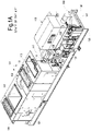
- Figs. 1A and 1B illustrate different isometric views of a turbogenerator skid including baseplate and relevant rotating machinery and auxiliaries arranged thereon according to the current art.
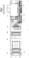
- Fig. 2 illustrates a top view of the turbogenerator skid of Figs. 1A , IB.
- a gas turbine 101 is supported on a baseplate 103, and drives into rotation an electric generator 105.
- the gas turbine 101 is usually arranged within a turbine acoustic enclosure 102, which is removed in Figs. 1A , IB and shown only in Fig.2 .
- the gas turbine 101 comprises an inlet plenum 107, a gas generator 109, a power turbine 111 and an exhaust gas collector 113.
- the power turbine 111 is connected through a shaft 115 and a gear box 117 to the load 105.
- electric control panels 119 are arranged on the opposite end of the gas turbine 101 .
- the starter 121 usually comprises an oil pump (visible in the drawing) which delivers oil under pressure to a hydraulic starter motor (not shown) which drives the gas turbine shaft into rotation before ignition of the fuel mixture.
- the rotating machinery comprised of the gas turbine 101 and the electric generator 105 is arranged on the baseplate 103, the length L whereof is determined by the axial length of the rotating machines arranged thereon with all auxiliary systems.
- the width W of the baseplate 103 is determined by the transverse dimensions of the rotating machines as well as by the dimensions of the auxiliary devices and components, which must be mounted on and supported by the baseplate 103. Among those auxiliary devices, in Figs.
- the starter 121 as mentioned above; a fuel skid 125, arranged adjacent the gas turbine 101 inside the gas turbine acoustic enclosure 102; lubrication oil electric pumps 127; vapor separator for the oil tank 129; heat exchangers 131 for cooling the lubrication oil; lubrication oil filters 133; a lubrication oil tank arranged under the gear box 117 and the oil pumps 127.
- the baseplate or skid 103 is comprised of a base frame formed by longitudinal beams 135 and cross beams 137 welded together to form a structure capable of supporting the static and dynamic loads generated by the rotating machines arranged on the baseplate 103.
- the subject matter disclosed herein concerns an improved type of baseplate for supporting rotating machinery (a gas turbine that drives a load, such as a centrifugal compressor, an electric generator, or a pump, with or without a speed reducer or multiplier load gear).
- a gas turbine that drives a load, such as a centrifugal compressor, an electric generator, or a pump, with or without a speed reducer or multiplier load gear.
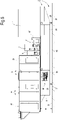
- a baseplate or skid indicated generally at 1 for mounting and supporting rotating machinery.
- the rotating machinery arranged on and supported by the baseplate 1 comprises a gas turbine 3 and a load 5 driven by the gas turbine 3.
- the load 5 can be comprised of a compressor, e.g. a centrifugal compressor.
- the load 5 can be comprised of an electric generator.
- a speed reducer or multiplier device 7 can be provided, for example a parallel axes gearbox, with vertically or horizontally oriented axes, or an epicyclical gearbox:
- the speed reducer or multiplier device 7 is provided when the rotation speed of the load 5 is different from the rotation speed of the gas turbine 3.
- An inlet shaft 9 connects the gas turbine 3 to the inlet of the speed manipulating device 7.
- a driven shaft 11 connects the output of the speed manipulating 7 to the load 5.
- the axis of the gas turbine 3 and the axis of the load 5 can be aligned along a vertical plane, thus reducing the width of the baseplate 1, i.e. the overall footprint thereof.
- the gas turbine 3 can comprise an inlet plenum 13, a gas generator 15, a combustor 17, a power turbine 19 and an exhaust gas collector 21, wherefrom the combustion gas generated by the gas turbine 3 is delivered to a stack and therefrom discharged in the atmosphere or used in a combined cycle, where the heat in the exhaust gas is used as a thermal source for a second thermodynamic cycle, or used in a co-generation system.
- the baseplate 1 comprises a central elongate torsion and bending resisting member 23, which is arranged under the load 5 the gas turbine 3 and extends there along.
- the elongate torsion and bending resisting member 23 is box-shaped, for example with a rectangular cross section.
- the elongate torsion and bending resisting member 23 has an elongate cross-section, with a longer side extending vertically and a shorter side extending horizontally.
- the width (horizontal dimension) of the cross section is preferably about half the height (vertical dimension) of the cross section of said elongate torsion and bending resisting member 23.
- the baseplate 1 further comprises cross members extending transversely to the central elongate torsion and bending resisting member 23.
- a load bearing cross member 25 is arranged crosswise under the load 5, approximately in a central position.
- the baseplate 1 is preferably provided with three support members 27, 29 and 31.
- the three support members 27, 29 and 31 are advantageously arranged at the vertices of an isosceles triangle.
- the two support members 27, 29 are arranged on the bottom side of the load bearing cross member 25 substantially symmetrically with respect to a center line of the baseplate 1.
- the third support member 31 is preferably arranged on the bottom side of the elongate torsion and bending resisting member 23, preferably under the gas turbine 3.
- the baseplate 1 can further comprise additional cross-members 33, 37 extending transversely to the elongate torsion and bending resisting member 23 and substantially parallel to the load bearing cross member 25.
- the two additional cross-members 33, 37 are advantageously located in different locations along the longitudinal extension of baseplate 1.
- two additional cross-members 33, 37 are located under the gas turbine 3. Additional cross-members can be provided between the load 5 and the gas turbine 3, according to needs.
- the additional cross-members 33, 37 do not require to provide a load-bearing function, but have rather the function of providing additional space for the arrangement of auxiliary devices or facilities.
- the elongate torsion and bending resisting member 23 comprises vertically extending, preferably planar side walls, for the purpose which will be described in greater detail here below.
- one, some or all of the load bearing cross members 27 and additional cross members 33, 37 can comprise planar, vertically extending side walls.
- said cross-members can also have, similarly to the elongate torsion and bending resisting member 23, a rectangular cross section elongated in the vertical direction.
- the gas turbine 3, including the inlet plenum 13 and the exhaust gas collector 21 can be mounted on and supported by a support platform 39.
- the support platform 39 can be formed by longitudinal and transversal beams 41, 43, forming a load bearing structure which can be acoustically insulated if required.
- the support platform 39 is connected to the elongate torsion and bending resisting member 23 in a rigid manner, and advantageously in a torque transmitting relationship.
- the support platform 39 further supports a gas turbine acoustic enclosure 45, which has been omitted in Fig. 3, 4 and 5 and is shown in Figs. 6 , 7 and 9 .
- the support platform 39 extends beyond the longitudinal end of the elongate torsion and bending resisting member 23 in an overhanging or cantilever fashion, as shown in particular in Fig. 3 .
- a free space 47 ( Fig. 3 ) is thus formed between a deck D, on which the baseplate 1 is mounted, and the support platform 39.
- the load 5 can be supported by a separate support platform 49, rigidly connected to the elongate torsion and bending resisting member 23, advantageously in a torque transmitting relationship.
- both rotating machines gas turbine 3 and load 5 could be supported by one and the same support platform extending lengthwise along the elongate torsion and bending resisting member 23 and placed on top thereof.
- the total vertical extension H of the elongate torsion and bending resisting member 23 and the support members 27, 29 and 31 is advantageously such that a person can access the space underneath the support platforms 49 and 39 in an erected position gaining access to apparatus, devices and auxiliary members of the gas turbine 3 and load 5, which can be located under the level of the support platforms 39 and 49.
- a fuel skid for example a gas skid 51
- a fuel skid 51 can be arranged under the support platform 39.
- the fuel skid 51 becomes thus entirely accessible by the personnel in charge of operation and maintenance of the rotating machinery directly and without the need of stepping on the baseplate 1.
- the sidewalls of the elongate torsion and bending resisting member 23 and of the cross-members 25, 33, 37 are sufficient to mount thereon or house therebetween a plurality of additional auxiliary devices, which thus become accessible from below the support platforms 49, 39.
- the additional cross-members 33, 37 are indeed provided for the purpose of increasing the vertical developing surface available for the installation of auxiliary devices and components, should the surface available on the elongate torsion and bending resisting member 23 and the load bearing cross-members 25 not be sufficient to receive all of the auxiliary devices and facilities which can be placed under the support platforms 39, 49.
- these additional cross-members 33, 37 do not have any specific load bearing function as far as the baseplate 1 is concerned.
- Lifting lugs can be arranged at the cross members 33 and 37 or in a different location on the baseplate, for complete skid or baseplate handling. Additional walls, provided with access maintenance doors, can be added to close the space available for auxiliary installation underneath platforms 39 and 49.
- a gas turbine starter 53 can also be arranged along the vertical surface available on the elongate torsion and bending resisting member 23 or in the area between the deck D and the lower surface of the support platforms 39, 49, as shown for example in Fig. 3 .
- the electric control panels of the gas turbine 3 and of the load 5 can also be placed on or against the vertical side surfaces of the elongate torsion and bending resisting member 23 and/or of the cross-members 25, 33, 37. Two such electric panels are schematically shown at 55 ( Fig. 3 ).
- auxiliary devices of the lubrication circuit are also arranged in the space made available under the level of the support platforms 39, 49 within the footprint thereof.
- oil-cooling heat exchangers 57 as well as oil filters 59 can be located under the support platforms 39 and 49, between the load bearing cross-member 25 and the additional cross-member 33 (see in particular Fig. 6 ).
- a bottom frame 61 can be arranged between those cross-members 25, 33, forming a mounting surface for the heat exchangers 57 and filters 59.
- On the opposite side of the elongate torsion and bending resisting member 23 see Fig.
- a lubrication oil tank 63 can be positioned in the space available between the load bearing cross-member 25 and the additional cross-member 33.
- oil pumps 65 and other auxiliary devices, for example an oil-vapor separator 67 can be arranged.
- the height H can range for example between approximately 1.80 and approximately 3.00 meters, preferably between 2.00 and 2.50 meters.
- a minimum height of 2.20 meters is particularly suitable for allowing easy access to personnel; a larger dimension can be adopted should this be required for example in order to house a larger number of auxiliary devices under the support platforms 39, 49 and/or if this is required to increase the torsional strength of the elongate torsion and bending resisting member 23 or for other reasons.
- auxiliary devices Moving several of the auxiliary devices from the interior of the gas turbine package 45 and/or more generally from the upper surface of the support platforms 39, 49, has additional important advantages. Temperature sensitive devices are moved away from hot areas of the gas turbine, reducing the risk of malfunctioning. Removing auxiliary devices from the top of the baseplate 1 and in particular from the gas turbine package allows a reduction of the cross-dimension W of the baseplate and therefore a reduction of the overall footprint, which is particularly advantageous in offshore applications.
- the space available under the support platform 39 between the cross-members 33 and 37 can also be used to house turbomachinery components (e.g. gas generator 15 or power turbine 19 of the gas turbine 3) or the entire gas turbine, requiring maintenance or replacement.
- the support platform 39 can be provided with a through aperture allowing removal of the turbomachinery requiring maintenance or replacement and move said machinery in the empty space available under the support platform 39. If the cross-member 37 is omitted or is provided only on one side of the elongate torsion and bending resisting member 23, the turbomachinery moved under the support platform 39 can also be transported away passing underneath the support platform 39 along the passageway formed by the space 47. This is particularly useful in case of two or more baseplates arranged side-by-side, since no intermediate space is required between adjacent baseplates 1 for the purpose of maintenance and turbine removal operations.
Landscapes
- Engineering & Computer Science (AREA)
- General Engineering & Computer Science (AREA)
- Mechanical Engineering (AREA)
- Power Engineering (AREA)
- Structures Of Non-Positive Displacement Pumps (AREA)
- Hydraulic Turbines (AREA)
- Motor Or Generator Frames (AREA)
- Centrifugal Separators (AREA)
- Superconductive Dynamoelectric Machines (AREA)
Claims (13)
- Grundplatte (1) zur Montage und Halterung rotierender Maschinen, einschließlich mindestens einer Gasturbine (3) und einer Last (5), die durch die Gasturbine (3) in Rotation versetzt wird, wobei die Grundplatte (1) umfasst:ein zentrales längliches Torsions- und Biegewiderstandselement (23); mindestens ein erstes lasttragendes Querelement (25), das sich quer zu dem länglichen Torsions- und Biegewiderstandselement (23) erstreckt; mindestens eine rotierende Maschinenhalterungsplattform (39), die starr mit dem länglichen Torsions- und Biegewiderstandselement (23) und mit dem ersten lasttragenden Querelement (25) verbunden ist; wobei das längliche Torsions- und Biegewiderstandselement (23) sich vertikal erstreckende Längsseitenwände zum Halten von Hilfsmitteln der rotierenden Maschine umfasst;und wobei die Maschinenhalterungsplattform (39) seitwärts über die Längsseitenwände des länglichen Torsions- und Biegewiderstandselements (23) hinausragt;dadurch gekennzeichnet, dass die Maschinenhalterungsplattform (39) in einer überhängenden Weise von einem Längsende des länglichen Torsions- und Biegewiderstandselements (23) hinausragt, um einen Freiraum (47) zwischen einem Deck, auf dem die Grundplatte (1) montiert werden soll, und der Halterungsplattform (39) verfügbar zu machen, um einen Durchgang auszubilden.
- Grundplatte nach Anspruch 1, wobei die Seitenwände eben sind.
- Grundplatte nach Anspruch 1 oder 2, wobei das längliche Torsions- und Biegewiderstandselement (23) eine vertikale Verlängerung aufweist, die ausreicht, damit ein Bediener auf die Hilfsmittel zugreifen kann, wobei er eine aufgerichtete und ergonomische Position beibehält und auf einen Raum unterhalb der Maschinenhalterungsplattform (39) zugreift.
- Grundplatte nach einem oder mehreren der vorstehenden Ansprüche, wobei das mindestens eine lasttragende Querelement (25) sich vertikal erstreckende Seitenwände zum Aufnehmen von Hilfsmitteln der rotierenden Maschine aufweist.
- Grundplatte nach einem oder mehreren der vorstehenden Ansprüche, ferner umfassend mindestens ein zusätzliches Querelement (33, 37), das sich parallel zu dem ersten lasttragenden Querelement (25) erstreckt und von diesem entlang der Längsverlängerung des länglichen Torsions- und Biegewiderstandselements (23) beabstandet ist.
- Grundplatte nach einem oder mehreren der vorstehenden Ansprüche, wobei das längliche Torsions- und Biegewiderstandselement (23) eine kastenförmige Struktur aufweist.
- Grundplatte nach einem oder mehreren der vorstehenden Ansprüche, ferner umfassend nur drei beabstandete Halterungselemente (27, 29, 31), wobei eines der Halterungselemente (31) mit einer unteren Fläche des länglichen Torsions- und Biegewiderstandselements (23) verbunden ist und zwei der drei Halterungselemente (27, 29) mit einer unteren Fläche des ersten lasttragenden Querelements (25) in jeweiligen Positionen verbunden sind, die im Allgemeinen symmetrisch in Bezug auf das längliche Torsions- und Biegewiderstandselement sind.
- Grundplatte nach einem oder mehreren der vorstehenden Ansprüche, wobei die Hilfsmittel eines oder mehrere von Folgendem einschließen: einen Kraftstoffzuführer (125); einen Turbinenstarter (53); einen Schmierölbehälter; Schmierölfilter (133); Schmierölpumpen (127); Dampfabscheider für den Öltank (129); Schmierölwärmetauscher (131); elektrische Steuerfelder (119).
- Turbomaschinensystem, umfassend:• eine rotierende Maschine, einschließlich mindestens einer Gasturbine (3) und einer Last (5), die durch die Gasturbine (3) in Rotation versetzt wird; und• eine Grundplatte nach einem oder mehreren der vorstehenden Ansprüche.
- System nach Anspruch 9, wobei die Turbine (3) in einem akustischen Turbinengehäuse untergebracht ist, das in einer überhängenden Weise über ein longitudinales Ende des länglichen Torsions- und Biegewiderstandselements (23) hinausragt.
- System nach Anspruch 9 oder 10, wobei die Last einen Zentrifugalkompressor, eine Pumpe oder einen elektrischen Generator umfasst.
- System nach einem oder mehreren der Ansprüche 9 bis 11, wobei die rotierende Maschine einen Drehzahlminderer oder ein Multiplikatorlastgetriebe umfasst, das zwischen der Gasturbine (3) und der Last (5) angeordnet ist, wobei die Drehzahlmanipulationsvorrichtung eine Einlasswelle einschließt, die antreibend mit der Gasturbine (3) verbunden ist, und eine Ausgangswelle, die antreibend mit der Last (5) verbunden ist.
- System nach Anspruch 12, wobei die Einlasswelle und die Auslasswelle des Drehzahlminderers oder des Multiplikatorlastgetriebes vertikal übereinander angeordnet sind, wobei sie eine Querabmessung der Maschinenhalterungsplattform (39) minimieren.
Applications Claiming Priority (2)
| Application Number | Priority Date | Filing Date | Title |
|---|---|---|---|
| IT000110A ITFI20130110A1 (it) | 2013-05-14 | 2013-05-14 | Baseplate for mounting and supporting rotating machinery and system comprising said baseplate |
| PCT/EP2014/059659 WO2014184141A1 (en) | 2013-05-14 | 2014-05-12 | Baseplate for mounting and supporting rotating machinery and system comprising said baseplate |
Publications (2)
| Publication Number | Publication Date |
|---|---|
| EP2997237A1 EP2997237A1 (de) | 2016-03-23 |
| EP2997237B1 true EP2997237B1 (de) | 2022-08-10 |
Family
ID=48917602
Family Applications (1)
| Application Number | Title | Priority Date | Filing Date |
|---|---|---|---|
| EP14725406.4A Active EP2997237B1 (de) | 2013-05-14 | 2014-05-12 | Grundplatte zur montage und halterung rotierender maschinen und system mit dieser grundplatte |
Country Status (8)
| Country | Link |
|---|---|
| US (1) | US10060293B2 (de) |
| EP (1) | EP2997237B1 (de) |
| JP (1) | JP6506740B2 (de) |
| CN (1) | CN105556066B (de) |
| CA (1) | CA2911959C (de) |
| IT (1) | ITFI20130110A1 (de) |
| RU (1) | RU2674821C2 (de) |
| WO (1) | WO2014184141A1 (de) |
Families Citing this family (62)
| Publication number | Priority date | Publication date | Assignee | Title |
|---|---|---|---|---|
| US10151422B2 (en) * | 2015-03-13 | 2018-12-11 | Sew-Eurodrive Gmbh & Co. Kg | Drivetrain package |
| US10030579B2 (en) * | 2016-09-21 | 2018-07-24 | General Electric Company | Systems and methods for a mobile power plant with improved mobility and reduced trailer count |
| JP6719597B2 (ja) | 2017-02-06 | 2020-07-08 | 三菱重工コンプレッサ株式会社 | 駆動機モジュール |
| US11624326B2 (en) | 2017-05-21 | 2023-04-11 | Bj Energy Solutions, Llc | Methods and systems for supplying fuel to gas turbine engines |
| US10927704B2 (en) * | 2018-05-17 | 2021-02-23 | Hamilton Sundstrand Corporation | Cooling configuration for a cold gas turbine generator assembly |
| CN108775264B (zh) * | 2018-07-18 | 2023-12-08 | 中国船舶重工集团公司第七0三研究所 | 一种低参数背压汽轮机双向挠性支承结构 |
| US11560845B2 (en) | 2019-05-15 | 2023-01-24 | Bj Energy Solutions, Llc | Mobile gas turbine inlet air conditioning system and associated methods |
| CN110374745A (zh) * | 2019-08-20 | 2019-10-25 | 烟台杰瑞石油装备技术有限公司 | 一种移动电力系统 |
| WO2021051399A1 (zh) | 2019-09-20 | 2021-03-25 | 烟台杰瑞石油装备技术有限公司 | 一种利用涡轮发动机驱动柱塞泵的水力压裂系统 |
| US12540575B2 (en) | 2019-09-06 | 2026-02-03 | Yantai Jereh Petroleum Equipment & Technologies Co., Ltd. | Hydraulic fracturing system for driving a plunger pump with a turbine engine and noise reduction thereof |
| CA3092863C (en) | 2019-09-13 | 2023-07-18 | Bj Energy Solutions, Llc | Fuel, communications, and power connection systems and related methods |
| US11015594B2 (en) | 2019-09-13 | 2021-05-25 | Bj Energy Solutions, Llc | Systems and method for use of single mass flywheel alongside torsional vibration damper assembly for single acting reciprocating pump |
| CA3092865C (en) | 2019-09-13 | 2023-07-04 | Bj Energy Solutions, Llc | Power sources and transmission networks for auxiliary equipment onboard hydraulic fracturing units and associated methods |
| CA3092829C (en) | 2019-09-13 | 2023-08-15 | Bj Energy Solutions, Llc | Methods and systems for supplying fuel to gas turbine engines |
| US11015536B2 (en) | 2019-09-13 | 2021-05-25 | Bj Energy Solutions, Llc | Methods and systems for supplying fuel to gas turbine engines |
| US10989180B2 (en) * | 2019-09-13 | 2021-04-27 | Bj Energy Solutions, Llc | Power sources and transmission networks for auxiliary equipment onboard hydraulic fracturing units and associated methods |
| CA3197583A1 (en) | 2019-09-13 | 2021-03-13 | Bj Energy Solutions, Llc | Fuel, communications, and power connection systems and related methods |
| US12338772B2 (en) | 2019-09-13 | 2025-06-24 | Bj Energy Solutions, Llc | Systems, assemblies, and methods to enhance intake air flow to a gas turbine engine of a hydraulic fracturing unit |
| US11002189B2 (en) | 2019-09-13 | 2021-05-11 | Bj Energy Solutions, Llc | Mobile gas turbine inlet air conditioning system and associated methods |
| US12065968B2 (en) | 2019-09-13 | 2024-08-20 | BJ Energy Solutions, Inc. | Systems and methods for hydraulic fracturing |
| CA3092868A1 (en) | 2019-09-13 | 2021-03-13 | Bj Energy Solutions, Llc | Turbine engine exhaust duct system and methods for noise dampening and attenuation |
| US10815764B1 (en) | 2019-09-13 | 2020-10-27 | Bj Energy Solutions, Llc | Methods and systems for operating a fleet of pumps |
| US11604113B2 (en) | 2019-09-13 | 2023-03-14 | Bj Energy Solutions, Llc | Fuel, communications, and power connection systems and related methods |
| US10895202B1 (en) | 2019-09-13 | 2021-01-19 | Bj Energy Solutions, Llc | Direct drive unit removal system and associated methods |
| CN110500255A (zh) * | 2019-09-20 | 2019-11-26 | 烟台杰瑞石油装备技术有限公司 | 一种压裂泵动力驱动系统 |
| US11702919B2 (en) | 2019-09-20 | 2023-07-18 | Yantai Jereh Petroleum Equipment & Technologies Co., Ltd. | Adaptive mobile power generation system |
| US12234712B2 (en) | 2019-09-20 | 2025-02-25 | Yantai Jereh Petroleum Equipment & Technologies Co., Ltd. | Adaptive mobile power generation system |
| CN110485982A (zh) | 2019-09-20 | 2019-11-22 | 烟台杰瑞石油装备技术有限公司 | 一种涡轮压裂设备 |
| CN112901292B (zh) | 2021-03-30 | 2025-12-09 | 烟台杰瑞石油装备技术有限公司 | 排气装置及其安装方法、涡轮压裂设备 |
| US11519395B2 (en) | 2019-09-20 | 2022-12-06 | Yantai Jereh Petroleum Equipment & Technologies Co., Ltd. | Turbine-driven fracturing system on semi-trailer |
| US12065916B2 (en) | 2019-09-20 | 2024-08-20 | Yantai Jereh Petroleum Equipment & Technologies Co., Ltd. | Hydraulic fracturing system for driving a plunger pump with a turbine engine |
| US12264568B2 (en) | 2019-09-20 | 2025-04-01 | Yantai Jereh Petroleum Equipment & Technologies Co., Ltd. | Fracturing devices |
| US12163514B2 (en) | 2019-09-20 | 2024-12-10 | Yantai Jereh Petroleum Equipment & Technologies Co., Ltd. | Connecting structure, plunger pump device and generator device |
| CN113047916A (zh) | 2021-01-11 | 2021-06-29 | 烟台杰瑞石油装备技术有限公司 | 可切换设备、井场及其控制方法、设备以及存储介质 |
| US12410695B2 (en) | 2019-09-20 | 2025-09-09 | Yantai Jereh Petroleum Equipment & Technologies Co., Ltd. | Turbine fracturing equipment |
| RU198343U1 (ru) * | 2020-04-16 | 2020-07-02 | Открытое акционерное общество "Пензенский завод компрессорного машиностроения" (ОАО "Пензкомпрессормаш") | Модульная компрессорная станция |
| US11708829B2 (en) | 2020-05-12 | 2023-07-25 | Bj Energy Solutions, Llc | Cover for fluid systems and related methods |
| US10968837B1 (en) | 2020-05-14 | 2021-04-06 | Bj Energy Solutions, Llc | Systems and methods utilizing turbine compressor discharge for hydrostatic manifold purge |
| US11428165B2 (en) | 2020-05-15 | 2022-08-30 | Bj Energy Solutions, Llc | Onboard heater of auxiliary systems using exhaust gases and associated methods |
| US11208880B2 (en) | 2020-05-28 | 2021-12-28 | Bj Energy Solutions, Llc | Bi-fuel reciprocating engine to power direct drive turbine fracturing pumps onboard auxiliary systems and related methods |
| US10961908B1 (en) | 2020-06-05 | 2021-03-30 | Bj Energy Solutions, Llc | Systems and methods to enhance intake air flow to a gas turbine engine of a hydraulic fracturing unit |
| US11208953B1 (en) | 2020-06-05 | 2021-12-28 | Bj Energy Solutions, Llc | Systems and methods to enhance intake air flow to a gas turbine engine of a hydraulic fracturing unit |
| US11109508B1 (en) | 2020-06-05 | 2021-08-31 | Bj Energy Solutions, Llc | Enclosure assembly for enhanced cooling of direct drive unit and related methods |
| US11111768B1 (en) | 2020-06-09 | 2021-09-07 | Bj Energy Solutions, Llc | Drive equipment and methods for mobile fracturing transportation platforms |
| US11022526B1 (en) | 2020-06-09 | 2021-06-01 | Bj Energy Solutions, Llc | Systems and methods for monitoring a condition of a fracturing component section of a hydraulic fracturing unit |
| US10954770B1 (en) | 2020-06-09 | 2021-03-23 | Bj Energy Solutions, Llc | Systems and methods for exchanging fracturing components of a hydraulic fracturing unit |
| US11066915B1 (en) | 2020-06-09 | 2021-07-20 | Bj Energy Solutions, Llc | Methods for detection and mitigation of well screen out |
| US11028677B1 (en) | 2020-06-22 | 2021-06-08 | Bj Energy Solutions, Llc | Stage profiles for operations of hydraulic systems and associated methods |
| US11939853B2 (en) | 2020-06-22 | 2024-03-26 | Bj Energy Solutions, Llc | Systems and methods providing a configurable staged rate increase function to operate hydraulic fracturing units |
| US11933153B2 (en) | 2020-06-22 | 2024-03-19 | Bj Energy Solutions, Llc | Systems and methods to operate hydraulic fracturing units using automatic flow rate and/or pressure control |
| US11125066B1 (en) | 2020-06-22 | 2021-09-21 | Bj Energy Solutions, Llc | Systems and methods to operate a dual-shaft gas turbine engine for hydraulic fracturing |
| US11473413B2 (en) | 2020-06-23 | 2022-10-18 | Bj Energy Solutions, Llc | Systems and methods to autonomously operate hydraulic fracturing units |
| US11466680B2 (en) | 2020-06-23 | 2022-10-11 | Bj Energy Solutions, Llc | Systems and methods of utilization of a hydraulic fracturing unit profile to operate hydraulic fracturing units |
| US11149533B1 (en) | 2020-06-24 | 2021-10-19 | Bj Energy Solutions, Llc | Systems to monitor, detect, and/or intervene relative to cavitation and pulsation events during a hydraulic fracturing operation |
| US11220895B1 (en) | 2020-06-24 | 2022-01-11 | Bj Energy Solutions, Llc | Automated diagnostics of electronic instrumentation in a system for fracturing a well and associated methods |
| US11193361B1 (en) | 2020-07-17 | 2021-12-07 | Bj Energy Solutions, Llc | Methods, systems, and devices to enhance fracturing fluid delivery to subsurface formations during high-pressure fracturing operations |
| DE102020131351A1 (de) * | 2020-11-26 | 2022-06-02 | Viessmann Climate Solutions Se | Verdichter |
| IT202100003356A1 (it) * | 2021-02-15 | 2022-08-15 | Nuovo Pignone Tecnologie Srl | Turbomachinery installation for an offshore platform |
| IT202100003647A1 (it) * | 2021-02-17 | 2022-08-17 | Nuovo Pignone Tecnologie Srl | Serbatoio di contenimento di allagamento |
| US11639654B2 (en) | 2021-05-24 | 2023-05-02 | Bj Energy Solutions, Llc | Hydraulic fracturing pumps to enhance flow of fracturing fluid into wellheads and related methods |
| CA3180024A1 (en) | 2021-10-25 | 2023-04-25 | Bj Energy Solutions, Llc | Systems and methods to reduce acoustic resonance or disrupt standing wave formation in a fluid manifold of a high-pressure fracturing system |
| CN116241758B (zh) * | 2022-12-15 | 2024-05-03 | 宜昌东阳建设工程有限公司 | 一种工地用红外智能监控报警装置 |
Citations (2)
| Publication number | Priority date | Publication date | Assignee | Title |
|---|---|---|---|---|
| WO1998050727A1 (en) * | 1997-05-06 | 1998-11-12 | Kvaerner Energy A.S | Base frame for a gas turbine |
| US20100162726A1 (en) * | 2008-12-29 | 2010-07-01 | Solar Turbines Incorporated | Mobile platform system for a gas turbine engine |
Family Cites Families (16)
| Publication number | Priority date | Publication date | Assignee | Title |
|---|---|---|---|---|
| CH612743A5 (de) | 1976-11-16 | 1979-08-15 | Sulzer Ag | |
| GB2101704B (en) * | 1981-05-14 | 1985-06-19 | Ingersoll Rand Co | Baseframes or skids for rotating machinery |
| US4694190A (en) | 1985-12-23 | 1987-09-15 | General Electric Company | Integral generator housing and base for a turbine generator |
| DE19837413A1 (de) * | 1997-08-25 | 1999-03-04 | Mitsubishi Heavy Ind Ltd | Gasturbinengeneratoranlage |
| JP4363799B2 (ja) * | 2001-06-08 | 2009-11-11 | 株式会社東芝 | タービン組立輸送架台および同架台を用いたタービン組立方法、輸送方法 |
| US7082896B2 (en) | 2004-03-31 | 2006-08-01 | Kohler Co. | Mounting system allowing for thermal expansion of an engine of a generator set |
| US7418802B2 (en) | 2005-09-09 | 2008-09-02 | Gichner Systems Group, Inc. | Expandable shelter system |
| EP1764542A1 (de) * | 2005-09-19 | 2007-03-21 | Siemens Aktiengesellschaft | Bausatz zur Erstellung einer Industrieanlage |
| WO2007060158A1 (de) * | 2005-11-24 | 2007-05-31 | Alstom Technology Ltd | Einhausung für die silobrennkammer einer gasturbine |
| US7552903B2 (en) | 2005-12-13 | 2009-06-30 | Solar Turbines Incorporated | Machine mounting system |
| FR2928601B1 (fr) | 2008-03-11 | 2011-09-09 | Alstom Transport Sa | Voiture de vehicule ferroviaire facilitant l'acces aux voyageurs a mobilite reduite |
| US9032620B2 (en) * | 2008-12-12 | 2015-05-19 | Nuovo Pignone S.P.A. | Method for moving and aligning heavy device |
| US7946554B2 (en) * | 2008-12-30 | 2011-05-24 | General Electric Company | Self-aligning support assembly and method for rotatable cylindrical components |
| RU87882U1 (ru) * | 2009-08-05 | 2009-10-27 | Семен Александрович Рихтман | Тренажер для интеллектуальных видов спорта |
| JP4897018B2 (ja) * | 2009-08-19 | 2012-03-14 | 三菱重工コンプレッサ株式会社 | 機械ユニットの配置システム |
| CN102926873A (zh) * | 2012-11-28 | 2013-02-13 | 北京华清燃气轮机与煤气化联合循环工程技术有限公司 | 一种燃气轮机支撑系统 |
-
2013
- 2013-05-14 IT IT000110A patent/ITFI20130110A1/it unknown
-
2014
- 2014-05-12 WO PCT/EP2014/059659 patent/WO2014184141A1/en not_active Ceased
- 2014-05-12 RU RU2015147197A patent/RU2674821C2/ru active
- 2014-05-12 EP EP14725406.4A patent/EP2997237B1/de active Active
- 2014-05-12 US US14/890,950 patent/US10060293B2/en active Active
- 2014-05-12 CA CA2911959A patent/CA2911959C/en active Active
- 2014-05-12 JP JP2016513320A patent/JP6506740B2/ja not_active Expired - Fee Related
- 2014-05-12 CN CN201480028134.2A patent/CN105556066B/zh active Active
Patent Citations (2)
| Publication number | Priority date | Publication date | Assignee | Title |
|---|---|---|---|---|
| WO1998050727A1 (en) * | 1997-05-06 | 1998-11-12 | Kvaerner Energy A.S | Base frame for a gas turbine |
| US20100162726A1 (en) * | 2008-12-29 | 2010-07-01 | Solar Turbines Incorporated | Mobile platform system for a gas turbine engine |
Also Published As
| Publication number | Publication date |
|---|---|
| ITFI20130110A1 (it) | 2014-11-15 |
| JP2016520753A (ja) | 2016-07-14 |
| JP6506740B2 (ja) | 2019-04-24 |
| CN105556066B (zh) | 2019-04-16 |
| RU2015147197A (ru) | 2017-06-19 |
| WO2014184141A1 (en) | 2014-11-20 |
| EP2997237A1 (de) | 2016-03-23 |
| RU2015147197A3 (de) | 2018-03-29 |
| RU2674821C2 (ru) | 2018-12-13 |
| US20160102581A1 (en) | 2016-04-14 |
| CA2911959A1 (en) | 2014-11-20 |
| CN105556066A (zh) | 2016-05-04 |
| US10060293B2 (en) | 2018-08-28 |
| CA2911959C (en) | 2021-04-13 |
Similar Documents
| Publication | Publication Date | Title |
|---|---|---|
| EP2997237B1 (de) | Grundplatte zur montage und halterung rotierender maschinen und system mit dieser grundplatte | |
| RU2635756C2 (ru) | Транспортабельный газотурбинный модуль, наземная газотурбинная установка с транспортабельным газотурбинным модулем и способ сборки такой газотурбинной установки | |
| EP2910711B1 (de) | Anordnung mit einem Motor | |
| KR102256891B1 (ko) | 해안 lng 플랜트용 가스 터빈 및 압축기 모듈 | |
| CN107859563A (zh) | 用于具有改进机动性和减小拖车数的移动发电厂的系统和方法 | |
| US10794287B2 (en) | Modular gas turbine system | |
| US10920669B2 (en) | Full turbomachinery module for LNG plants or the like | |
| CA2963854A1 (en) | Multi-point mounting system for rotating machinery | |
| EP3423692B1 (de) | Montagerahmen für generator mit verringertem abstand | |
| JP7724867B2 (ja) | 洋上プラットフォーム用のターボ機械設備 | |
| WO1985001987A1 (en) | Transportable power unit |
Legal Events
| Date | Code | Title | Description |
|---|---|---|---|
| PUAI | Public reference made under article 153(3) epc to a published international application that has entered the european phase |
Free format text: ORIGINAL CODE: 0009012 |
|
| 17P | Request for examination filed |
Effective date: 20151214 |
|
| AK | Designated contracting states |
Kind code of ref document: A1 Designated state(s): AL AT BE BG CH CY CZ DE DK EE ES FI FR GB GR HR HU IE IS IT LI LT LU LV MC MK MT NL NO PL PT RO RS SE SI SK SM TR |
|
| AX | Request for extension of the european patent |
Extension state: BA ME |
|
| DAX | Request for extension of the european patent (deleted) | ||
| STAA | Information on the status of an ep patent application or granted ep patent |
Free format text: STATUS: EXAMINATION IS IN PROGRESS |
|
| 17Q | First examination report despatched |
Effective date: 20200130 |
|
| RAP1 | Party data changed (applicant data changed or rights of an application transferred) |
Owner name: NUOVO PIGNONE TECNOLOGIE - S.R.L. |
|
| GRAP | Despatch of communication of intention to grant a patent |
Free format text: ORIGINAL CODE: EPIDOSNIGR1 |
|
| STAA | Information on the status of an ep patent application or granted ep patent |
Free format text: STATUS: GRANT OF PATENT IS INTENDED |
|
| INTG | Intention to grant announced |
Effective date: 20220429 |
|
| RIN1 | Information on inventor provided before grant (corrected) |
Inventor name: DEL BONO, ALESSANDRO |
|
| GRAS | Grant fee paid |
Free format text: ORIGINAL CODE: EPIDOSNIGR3 |
|
| GRAA | (expected) grant |
Free format text: ORIGINAL CODE: 0009210 |
|
| STAA | Information on the status of an ep patent application or granted ep patent |
Free format text: STATUS: THE PATENT HAS BEEN GRANTED |
|
| AK | Designated contracting states |
Kind code of ref document: B1 Designated state(s): AL AT BE BG CH CY CZ DE DK EE ES FI FR GB GR HR HU IE IS IT LI LT LU LV MC MK MT NL NO PL PT RO RS SE SI SK SM TR |
|
| REG | Reference to a national code |
Ref country code: AT Ref legal event code: REF Ref document number: 1510697 Country of ref document: AT Kind code of ref document: T Effective date: 20220815 Ref country code: CH Ref legal event code: EP |
|
| REG | Reference to a national code |
Ref country code: DE Ref legal event code: R096 Ref document number: 602014084561 Country of ref document: DE |
|
| REG | Reference to a national code |
Ref country code: IE Ref legal event code: FG4D |
|
| REG | Reference to a national code |
Ref country code: SE Ref legal event code: TRGR |
|
| REG | Reference to a national code |
Ref country code: NO Ref legal event code: T2 Effective date: 20220810 |
|
| REG | Reference to a national code |
Ref country code: NL Ref legal event code: MP Effective date: 20220810 |
|
| REG | Reference to a national code |
Ref country code: LT Ref legal event code: MG9D |
|
| PG25 | Lapsed in a contracting state [announced via postgrant information from national office to epo] |
Ref country code: RS Free format text: LAPSE BECAUSE OF FAILURE TO SUBMIT A TRANSLATION OF THE DESCRIPTION OR TO PAY THE FEE WITHIN THE PRESCRIBED TIME-LIMIT Effective date: 20220810 Ref country code: PT Free format text: LAPSE BECAUSE OF FAILURE TO SUBMIT A TRANSLATION OF THE DESCRIPTION OR TO PAY THE FEE WITHIN THE PRESCRIBED TIME-LIMIT Effective date: 20221212 Ref country code: NL Free format text: LAPSE BECAUSE OF FAILURE TO SUBMIT A TRANSLATION OF THE DESCRIPTION OR TO PAY THE FEE WITHIN THE PRESCRIBED TIME-LIMIT Effective date: 20220810 Ref country code: LV Free format text: LAPSE BECAUSE OF FAILURE TO SUBMIT A TRANSLATION OF THE DESCRIPTION OR TO PAY THE FEE WITHIN THE PRESCRIBED TIME-LIMIT Effective date: 20220810 Ref country code: LT Free format text: LAPSE BECAUSE OF FAILURE TO SUBMIT A TRANSLATION OF THE DESCRIPTION OR TO PAY THE FEE WITHIN THE PRESCRIBED TIME-LIMIT Effective date: 20220810 Ref country code: FI Free format text: LAPSE BECAUSE OF FAILURE TO SUBMIT A TRANSLATION OF THE DESCRIPTION OR TO PAY THE FEE WITHIN THE PRESCRIBED TIME-LIMIT Effective date: 20220810 Ref country code: ES Free format text: LAPSE BECAUSE OF FAILURE TO SUBMIT A TRANSLATION OF THE DESCRIPTION OR TO PAY THE FEE WITHIN THE PRESCRIBED TIME-LIMIT Effective date: 20220810 |
|
| REG | Reference to a national code |
Ref country code: AT Ref legal event code: MK05 Ref document number: 1510697 Country of ref document: AT Kind code of ref document: T Effective date: 20220810 |
|
| PG25 | Lapsed in a contracting state [announced via postgrant information from national office to epo] |
Ref country code: PL Free format text: LAPSE BECAUSE OF FAILURE TO SUBMIT A TRANSLATION OF THE DESCRIPTION OR TO PAY THE FEE WITHIN THE PRESCRIBED TIME-LIMIT Effective date: 20220810 Ref country code: IS Free format text: LAPSE BECAUSE OF FAILURE TO SUBMIT A TRANSLATION OF THE DESCRIPTION OR TO PAY THE FEE WITHIN THE PRESCRIBED TIME-LIMIT Effective date: 20221210 Ref country code: HR Free format text: LAPSE BECAUSE OF FAILURE TO SUBMIT A TRANSLATION OF THE DESCRIPTION OR TO PAY THE FEE WITHIN THE PRESCRIBED TIME-LIMIT Effective date: 20220810 Ref country code: GR Free format text: LAPSE BECAUSE OF FAILURE TO SUBMIT A TRANSLATION OF THE DESCRIPTION OR TO PAY THE FEE WITHIN THE PRESCRIBED TIME-LIMIT Effective date: 20221111 |
|
| PG25 | Lapsed in a contracting state [announced via postgrant information from national office to epo] |
Ref country code: SM Free format text: LAPSE BECAUSE OF FAILURE TO SUBMIT A TRANSLATION OF THE DESCRIPTION OR TO PAY THE FEE WITHIN THE PRESCRIBED TIME-LIMIT Effective date: 20220810 Ref country code: RO Free format text: LAPSE BECAUSE OF FAILURE TO SUBMIT A TRANSLATION OF THE DESCRIPTION OR TO PAY THE FEE WITHIN THE PRESCRIBED TIME-LIMIT Effective date: 20220810 Ref country code: DK Free format text: LAPSE BECAUSE OF FAILURE TO SUBMIT A TRANSLATION OF THE DESCRIPTION OR TO PAY THE FEE WITHIN THE PRESCRIBED TIME-LIMIT Effective date: 20220810 Ref country code: CZ Free format text: LAPSE BECAUSE OF FAILURE TO SUBMIT A TRANSLATION OF THE DESCRIPTION OR TO PAY THE FEE WITHIN THE PRESCRIBED TIME-LIMIT Effective date: 20220810 Ref country code: AT Free format text: LAPSE BECAUSE OF FAILURE TO SUBMIT A TRANSLATION OF THE DESCRIPTION OR TO PAY THE FEE WITHIN THE PRESCRIBED TIME-LIMIT Effective date: 20220810 |
|
| REG | Reference to a national code |
Ref country code: DE Ref legal event code: R097 Ref document number: 602014084561 Country of ref document: DE |
|
| PG25 | Lapsed in a contracting state [announced via postgrant information from national office to epo] |
Ref country code: SK Free format text: LAPSE BECAUSE OF FAILURE TO SUBMIT A TRANSLATION OF THE DESCRIPTION OR TO PAY THE FEE WITHIN THE PRESCRIBED TIME-LIMIT Effective date: 20220810 Ref country code: EE Free format text: LAPSE BECAUSE OF FAILURE TO SUBMIT A TRANSLATION OF THE DESCRIPTION OR TO PAY THE FEE WITHIN THE PRESCRIBED TIME-LIMIT Effective date: 20220810 |
|
| PLBE | No opposition filed within time limit |
Free format text: ORIGINAL CODE: 0009261 |
|
| STAA | Information on the status of an ep patent application or granted ep patent |
Free format text: STATUS: NO OPPOSITION FILED WITHIN TIME LIMIT |
|
| PG25 | Lapsed in a contracting state [announced via postgrant information from national office to epo] |
Ref country code: AL Free format text: LAPSE BECAUSE OF FAILURE TO SUBMIT A TRANSLATION OF THE DESCRIPTION OR TO PAY THE FEE WITHIN THE PRESCRIBED TIME-LIMIT Effective date: 20220810 |
|
| P01 | Opt-out of the competence of the unified patent court (upc) registered |
Effective date: 20230526 |
|
| 26N | No opposition filed |
Effective date: 20230511 |
|
| PG25 | Lapsed in a contracting state [announced via postgrant information from national office to epo] |
Ref country code: SI Free format text: LAPSE BECAUSE OF FAILURE TO SUBMIT A TRANSLATION OF THE DESCRIPTION OR TO PAY THE FEE WITHIN THE PRESCRIBED TIME-LIMIT Effective date: 20220810 |
|
| PG25 | Lapsed in a contracting state [announced via postgrant information from national office to epo] |
Ref country code: MC Free format text: LAPSE BECAUSE OF FAILURE TO SUBMIT A TRANSLATION OF THE DESCRIPTION OR TO PAY THE FEE WITHIN THE PRESCRIBED TIME-LIMIT Effective date: 20220810 |
|
| GBPC | Gb: european patent ceased through non-payment of renewal fee |
Effective date: 20230512 |
|
| REG | Reference to a national code |
Ref country code: BE Ref legal event code: MM Effective date: 20230531 |
|
| PG25 | Lapsed in a contracting state [announced via postgrant information from national office to epo] |
Ref country code: MC Free format text: LAPSE BECAUSE OF FAILURE TO SUBMIT A TRANSLATION OF THE DESCRIPTION OR TO PAY THE FEE WITHIN THE PRESCRIBED TIME-LIMIT Effective date: 20220810 Ref country code: LU Free format text: LAPSE BECAUSE OF NON-PAYMENT OF DUE FEES Effective date: 20230512 |
|
| REG | Reference to a national code |
Ref country code: IE Ref legal event code: MM4A |
|
| PG25 | Lapsed in a contracting state [announced via postgrant information from national office to epo] |
Ref country code: IE Free format text: LAPSE BECAUSE OF NON-PAYMENT OF DUE FEES Effective date: 20230512 |
|
| PG25 | Lapsed in a contracting state [announced via postgrant information from national office to epo] |
Ref country code: IE Free format text: LAPSE BECAUSE OF NON-PAYMENT OF DUE FEES Effective date: 20230512 Ref country code: GB Free format text: LAPSE BECAUSE OF NON-PAYMENT OF DUE FEES Effective date: 20230512 |
|
| PG25 | Lapsed in a contracting state [announced via postgrant information from national office to epo] |
Ref country code: IT Free format text: LAPSE BECAUSE OF FAILURE TO SUBMIT A TRANSLATION OF THE DESCRIPTION OR TO PAY THE FEE WITHIN THE PRESCRIBED TIME-LIMIT Effective date: 20220810 Ref country code: FR Free format text: LAPSE BECAUSE OF NON-PAYMENT OF DUE FEES Effective date: 20230531 Ref country code: BE Free format text: LAPSE BECAUSE OF NON-PAYMENT OF DUE FEES Effective date: 20230531 |
|
| PG25 | Lapsed in a contracting state [announced via postgrant information from national office to epo] |
Ref country code: BG Free format text: LAPSE BECAUSE OF FAILURE TO SUBMIT A TRANSLATION OF THE DESCRIPTION OR TO PAY THE FEE WITHIN THE PRESCRIBED TIME-LIMIT Effective date: 20220810 |
|
| PG25 | Lapsed in a contracting state [announced via postgrant information from national office to epo] |
Ref country code: BG Free format text: LAPSE BECAUSE OF FAILURE TO SUBMIT A TRANSLATION OF THE DESCRIPTION OR TO PAY THE FEE WITHIN THE PRESCRIBED TIME-LIMIT Effective date: 20220810 |
|
| PGFP | Annual fee paid to national office [announced via postgrant information from national office to epo] |
Ref country code: DE Payment date: 20250423 Year of fee payment: 12 |
|
| PGFP | Annual fee paid to national office [announced via postgrant information from national office to epo] |
Ref country code: NO Payment date: 20250424 Year of fee payment: 12 |
|
| PGFP | Annual fee paid to national office [announced via postgrant information from national office to epo] |
Ref country code: CH Payment date: 20250601 Year of fee payment: 12 |
|
| PG25 | Lapsed in a contracting state [announced via postgrant information from national office to epo] |
Ref country code: CY Free format text: LAPSE BECAUSE OF FAILURE TO SUBMIT A TRANSLATION OF THE DESCRIPTION OR TO PAY THE FEE WITHIN THE PRESCRIBED TIME-LIMIT; INVALID AB INITIO Effective date: 20140512 |
|
| PGFP | Annual fee paid to national office [announced via postgrant information from national office to epo] |
Ref country code: SE Payment date: 20250423 Year of fee payment: 12 |
|
| PG25 | Lapsed in a contracting state [announced via postgrant information from national office to epo] |
Ref country code: HU Free format text: LAPSE BECAUSE OF FAILURE TO SUBMIT A TRANSLATION OF THE DESCRIPTION OR TO PAY THE FEE WITHIN THE PRESCRIBED TIME-LIMIT; INVALID AB INITIO Effective date: 20140512 |
|
| PG25 | Lapsed in a contracting state [announced via postgrant information from national office to epo] |
Ref country code: TR Free format text: LAPSE BECAUSE OF FAILURE TO SUBMIT A TRANSLATION OF THE DESCRIPTION OR TO PAY THE FEE WITHIN THE PRESCRIBED TIME-LIMIT Effective date: 20220810 |