EP2996532B1 - Staubabsaugvorrichtung für eine handwerkzeugmaschine - Google Patents
Staubabsaugvorrichtung für eine handwerkzeugmaschine Download PDFInfo
- Publication number
- EP2996532B1 EP2996532B1 EP14724079.0A EP14724079A EP2996532B1 EP 2996532 B1 EP2996532 B1 EP 2996532B1 EP 14724079 A EP14724079 A EP 14724079A EP 2996532 B1 EP2996532 B1 EP 2996532B1
- Authority
- EP
- European Patent Office
- Prior art keywords
- dust
- filter
- extraction device
- fins
- dust extraction
- Prior art date
- Legal status (The legal status is an assumption and is not a legal conclusion. Google has not performed a legal analysis and makes no representation as to the accuracy of the status listed.)
- Active
Links
Images



Classifications
-
- B—PERFORMING OPERATIONS; TRANSPORTING
- B23—MACHINE TOOLS; METAL-WORKING NOT OTHERWISE PROVIDED FOR
- B23Q—DETAILS, COMPONENTS, OR ACCESSORIES FOR MACHINE TOOLS, e.g. ARRANGEMENTS FOR COPYING OR CONTROLLING; MACHINE TOOLS IN GENERAL CHARACTERISED BY THE CONSTRUCTION OF PARTICULAR DETAILS OR COMPONENTS; COMBINATIONS OR ASSOCIATIONS OF METAL-WORKING MACHINES, NOT DIRECTED TO A PARTICULAR RESULT
- B23Q11/00—Accessories fitted to machine tools for keeping tools or parts of the machine in good working condition or for cooling work; Safety devices specially combined with or arranged in, or specially adapted for use in connection with, machine tools
- B23Q11/0042—Devices for removing chips
- B23Q11/0071—Devices for removing chips dust collectors for hand tools
-
- A—HUMAN NECESSITIES
- A47—FURNITURE; DOMESTIC ARTICLES OR APPLIANCES; COFFEE MILLS; SPICE MILLS; SUCTION CLEANERS IN GENERAL
- A47L—DOMESTIC WASHING OR CLEANING; SUCTION CLEANERS IN GENERAL
- A47L7/00—Suction cleaners adapted for additional purposes; Tables with suction openings for cleaning purposes; Containers for cleaning articles by suction; Suction cleaners adapted to cleaning of brushes; Suction cleaners adapted to taking-up liquids
- A47L7/0095—Suction cleaners or attachments adapted to collect dust or waste from power tools
-
- A—HUMAN NECESSITIES
- A47—FURNITURE; DOMESTIC ARTICLES OR APPLIANCES; COFFEE MILLS; SPICE MILLS; SUCTION CLEANERS IN GENERAL
- A47L—DOMESTIC WASHING OR CLEANING; SUCTION CLEANERS IN GENERAL
- A47L5/00—Structural features of suction cleaners
- A47L5/12—Structural features of suction cleaners with power-driven air-pumps or air-compressors, e.g. driven by motor vehicle engine vacuum
- A47L5/22—Structural features of suction cleaners with power-driven air-pumps or air-compressors, e.g. driven by motor vehicle engine vacuum with rotary fans
-
- A—HUMAN NECESSITIES
- A47—FURNITURE; DOMESTIC ARTICLES OR APPLIANCES; COFFEE MILLS; SPICE MILLS; SUCTION CLEANERS IN GENERAL
- A47L—DOMESTIC WASHING OR CLEANING; SUCTION CLEANERS IN GENERAL
- A47L9/00—Details or accessories of suction cleaners, e.g. mechanical means for controlling the suction or for effecting pulsating action; Storing devices specially adapted to suction cleaners or parts thereof; Carrying-vehicles specially adapted for suction cleaners
- A47L9/02—Nozzles
-
- A—HUMAN NECESSITIES
- A47—FURNITURE; DOMESTIC ARTICLES OR APPLIANCES; COFFEE MILLS; SPICE MILLS; SUCTION CLEANERS IN GENERAL
- A47L—DOMESTIC WASHING OR CLEANING; SUCTION CLEANERS IN GENERAL
- A47L9/00—Details or accessories of suction cleaners, e.g. mechanical means for controlling the suction or for effecting pulsating action; Storing devices specially adapted to suction cleaners or parts thereof; Carrying-vehicles specially adapted for suction cleaners
- A47L9/10—Filters; Dust separators; Dust removal; Automatic exchange of filters
- A47L9/102—Dust separators
-
- A—HUMAN NECESSITIES
- A47—FURNITURE; DOMESTIC ARTICLES OR APPLIANCES; COFFEE MILLS; SPICE MILLS; SUCTION CLEANERS IN GENERAL
- A47L—DOMESTIC WASHING OR CLEANING; SUCTION CLEANERS IN GENERAL
- A47L9/00—Details or accessories of suction cleaners, e.g. mechanical means for controlling the suction or for effecting pulsating action; Storing devices specially adapted to suction cleaners or parts thereof; Carrying-vehicles specially adapted for suction cleaners
- A47L9/10—Filters; Dust separators; Dust removal; Automatic exchange of filters
- A47L9/12—Dry filters
-
- A—HUMAN NECESSITIES
- A47—FURNITURE; DOMESTIC ARTICLES OR APPLIANCES; COFFEE MILLS; SPICE MILLS; SUCTION CLEANERS IN GENERAL
- A47L—DOMESTIC WASHING OR CLEANING; SUCTION CLEANERS IN GENERAL
- A47L9/00—Details or accessories of suction cleaners, e.g. mechanical means for controlling the suction or for effecting pulsating action; Storing devices specially adapted to suction cleaners or parts thereof; Carrying-vehicles specially adapted for suction cleaners
- A47L9/10—Filters; Dust separators; Dust removal; Automatic exchange of filters
- A47L9/12—Dry filters
- A47L9/122—Dry filters flat
Definitions
- the present invention relates to a dust extraction device according to the preamble of claim 1.
- Generic dust extraction devices are, for example, from US Pat DE 102010040094 A1 , US 2005/281627 , DE10 2009 038230 A1 , U.S. 6,101,666 A and the DE 10 2008 016956 known.
- the dust filter needs to be replaced regularly as it becomes stuck with dust.
- the dust extraction device has a fan for generating an air flow, an intake connection for sucking in dust-laden air from a tool, and a collecting container provided for collecting dust.
- the collecting container has an intake opening connected to the intake port and an exhaust opening connected to the fan.
- a filter is arranged to cover the exhaust opening for separating dust into the collecting container.
- the filter has a plurality of lamellae stacked next to one another in a direction (y) perpendicular to the direction (z) of the air flow. The slats are inclined towards each other. The inclination of the lamellas reduces the adhesion of dust to the lamellas.
- One embodiment provides that the outermost slats are inclined to one another by 3 degrees to 10 degrees.
- the adjacent slats should be inclined to each other. An incline of more than 10 minutes of arc appears sufficient. A greater inclination leads not only to a loss of performance but also to an increased space requirement.
- One embodiment provides that the slats are fastened in a frame which is bendable in one direction (z) of the air flow and the frame is placed on a base which is convexly raised opposite to the direction (z).
- a face of the filter against which the flow is flowing is less than 10% larger than a face of the filter facing away from it.
- the fan has to build up a pressure difference of several mbar to the intake manifold. Since only a small motor can be used for the hand-held devices, pressure losses must be avoided under all circumstances. A cuboid or almost cuboid structure is therefore essential.
- the base has a guide which is inclined in relation to the direction (z) of the air flow and on which one of the slats is placed.
- Fig. 1 shows a dust extraction device 1 which is applied to a hammer drill 2 .
- the hammer drill 2 generates 3 holes in rock, concrete, etc. by means of a chiseling drill.
- the dust extraction device 1 sucks the drillings, in particular the fine dust, from the borehole.
- the hammer drill 2 by way of example has a tool holder 4 in which the drill 3 can be inserted and locked.
- the tool holder 4 is coupled via a rotary drive 5 to a motor 6 which drives the tool holder 4 to rotate about a working axis 7 .
- a pneumatic hammer mechanism can apply blows to the drill 3 along the working axis 7 in the working direction 8 .
- the hammer mechanism is also driven by the motor 6 .
- the motor 6 drives an eccentric wheel 9 which forces an exciter piston 10 to periodically move back and forth.
- a striker 11 is coupled to the movement of the exciter piston 10 by an air spring 12 .
- the drive components are arranged in a machine housing 13 .
- a handle 14 for holding and guiding the hammer drill 2 during operation can be connected to the machine housing 13 in a rigid or damped manner. The user can put the motor 6 into operation by means of a main switch 15 .
- the dust extraction device 1 has a housing 16 with a holder 17.
- the user can fasten the dust extraction device 1 to the rotary hammer 2 by means of the holder 17 .
- the bracket 17 includes a movable pin, a pawl, a clamp, etc.
- the dust extraction device 1 has a fan 18 which generates an air flow 19 .
- the blower 18 shown in the example has a fan wheel 20 and an electric motor 21 driving the fan wheel 20.
- the fan wheel 20 sucks in the air in the radial direction and blows the air out in the axial direction through corresponding openings in the housing 16 .
- a suction nozzle 23 of the dust extraction device 1 is arranged in the immediate vicinity of the drill 3 .
- the suction nozzle 23 can for example have a sleeve 24 which surrounds the drill 3 .
- the exemplary sleeve 24 has a sealing ring 25 which comes to rest against the drill 3 .
- the drill dust is sucked in within the shank of the drill 3 .
- the suction nozzle 23 preferably also surrounds the drill and at the same time rests on the workpiece.
- the dust-laden air picked up by the suction nozzle 23 is transported by the air stream 19 into a collecting container 22 .
- the suction nozzle 23 is via a hose 26, a rigid pipe, a telescopic pipe or another tubular channel connected to a suction opening 27 of the collecting container 22 .
- the collecting container 22 has a flat blow-out opening 28 which is completely covered by a filter 29 .
- the fan 18 is arranged behind the filter 29 .
- the dust in the air stream 19 is separated on the filter 29 and remains in the collecting container 22 .
- the air stream 19 reaching the fan 18 is dust-free.
- the housing 30 of the collecting container 22 is designed airtight in such a way that the entire air flow 19 entering at the suction opening 27 only exits through the exhaust opening 28 .
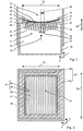
- Fig. 2 shows the exemplary built-in filter 29 in a cross section in the plane II-II.
- Fig. 3 shows a plan view of the face 31 of the filter 29 against which the flow occurs.
- the filter 29 has an essentially cuboid structure.
- the dimensions of the cuboid are referred to below as usual as length 32, width 33 and height 34 , the associated axes are referred to as x-axis, y-axis and z-axis.
- An end face 31 facing the flow on which the dust accumulates, and an end face 35 facing away from the flow , which remains essentially clean, are perpendicular to the z-axis and largely of the same size.
- the end faces 31, 35 are equal to the product of length 32 and width 33 of the filter 29.
- the deviation is less than 10%.
- the same dimensions avoid a pressure drop.
- the filter 29 has a membrane 36, the surface of which is flown through many times larger than the end faces 31, 35 .
- the membrane 36 is composed of a plurality of lamellae 37, preferably of the same shape.
- the lamellae 37 essentially consist of two opposite flat sides 38.
- the sides 38 are made of the permeable membrane 36, which has a pore size designed to hold back the dust.
- the sides 38 are separated from one another by a thin, flat channel 39 . Dust-laden air can penetrate the sides 38 , separating the dust, and flow off in the channel 39 between the sides 38 .
- the sides 38 are preferably the same size.
- the sides 38 are preferably parallel to one another or inclined to one another at a slight angle, less than 5 degrees.
- the sides 38 are connected to one another at a head line 40 .
- Adjacent slats 37 are each connected to one another by a base line 41 of the sides 38 .
- the lamellae 37 are aligned with one another parallel to the x-axis, ie the sides 38, top lines 40 and foot lines 41 are parallel to one another.
- the lamellae 37 follow one another in the y direction, preferably without partially overlapping in this direction.
- the lamellae 37 are inclined at a slight angle with respect to the z-axis, which will be discussed further below.
- the lamellas 37 point with their head lines 40 against the air flow 19.
- the lamellae 37 are aligned in a fanned manner.
- the lamellae 37 are inclined to one another.
- the inclination 42 between the lamellas 37 is determined between the gravity planes of their sides 38 or, equivalently, the inclination 42 is determined between the sides 38 pointing in the same direction.
- a distance 43 between adjacent slats 37 decreases in the direction of the air flow 19.
- the inclination 42 between all adjacent slats 37 is not equal to zero, preferably the same size.
- the two outermost lamellae 44 along the y-axis have a relative inclination 42 in the range between 3 degrees and 10 degrees. The flow therefore continues to essentially come from an axial direction.
- the membrane 36 is formed, for example, from a sheet of folded paper or a folded textile.
- the pores of the membrane 36 can expediently be smaller than 5 ⁇ m on average in order to hold back dust.
- the sheet is folded several times in alternately opposite folding directions along fold lines parallel to the x-axis.
- the first side surface 38 of the lamella results as a fold in the folding direction and the second side 45 as a subsequent fold in the opposite direction.
- the two sides 38, 45 are connected along a fold line which forms the top line 40
- the adjacent slats 37 are likewise connected along a fold line which forms the base line 41 .
- the distance between the sides 38 of a lamella 37 is less than the distance between two adjacent lamellae 37.
- the filter 29 has a frame 46.
- the frame 46 connects the foot lines 41 along the y-axis.
- the membrane 36 can no longer unfold.
- the height of the frame 46 is preferably significantly less than the height 34 of the folded membrane 36.
- the edges 40 facing the stream are not fixed in the frame 46 , but rather are movable.
- the preferred frame 46 is made of an elastic plastic, for example rubber.
- the exhaust opening 28 of the collecting container 22 is covered by the filter 29 .
- the blow-out opening 28 has a frame-shaped base 47 which surrounds the blow-out opening 28 .
- the frame 46 of the filter 29 lies in a form-fitting manner on the base 47 in order to avoid leakage.
- the frame-shaped base 47 has first areas 48, which run along the x-axis, that is, along the edges 40, 41 of the lamellae 44 , and second areas 49, which run along the y-axis, ie essentially perpendicular to the lamellae 44 first regions 48 are designed to be essentially straight and lying in one plane.
- the second areas 49 are concave along the y-axis.
- the second region 49 is closer to the interior of the collecting container 22 in the middle than at the edge. ( Fig. 4 ).
- the flexible frame 46 of the filter 29 pressed against the base 47 is correspondingly deformed.
- the edges 41 facing away from it are thus at different heights along the z-axis.
- the folded membrane 36 spreads in a fan shape; the slats 37 receive the relative inclination 42 to one another.
- the housing 16 of the dust extraction device 1 has a base 50 which lies opposite the base 47 of the collecting container 22 .
- the frame 46 of the filter 29 is clamped between the two bases 47, 50 .
- the base 50 of the housing 16 has a convex section along the y-axis, which is preferably complementary to the second region 49 of the base 47 of the collecting container 22 . In one embodiment, only the housing 16 is provided with a convexly curved base 50 .
- Fig. 5 shows a further embodiment.
- the housing 16 is provided with guide plates 54 .
- the guide plates 54 are inclined with respect to the z-axis, equal to the inclination 42 of the outermost or outer lamellae 44.
- the outer lamellae 44 are placed with the channel 39 on the guide plates 54 .
- the guide plates 54 cause or support the fan-like spreading of the membrane 36 out of the lamellae 37.
- a guide on the side facing away from it proves to be advantageous, since the guide 51 does not offer a seed point for the accumulation of dust.
- FIGS. 6 and 7 show a further embodiment.
- the lamellae 37 are provided with spacers 52 .
- the spacers 52 are arranged on the head line 40 .
- the spacers 52 have a dimension along the y-axis which is greater than the distance from the foot line 41 .
- the head lines 40 are further apart than the foot lines 41 in order to achieve the desired fan-like spreading.
- the spacers 52 can be placed onto the head lines 40 as an attachment.
- the spacers 52 are preferably embossed into the membrane 36 before the membrane 36 is folded into the lamellae 37 .
Landscapes
- Engineering & Computer Science (AREA)
- Mechanical Engineering (AREA)
- Percussive Tools And Related Accessories (AREA)
- Filtering Of Dispersed Particles In Gases (AREA)
Description
- Die vorliegende Erfindung betrifft eine Staubabsaugvorrichtung gemäß dem Oberbegriff von Anspruch 1. Gattungsgemässe Staubabsaugvorrichtungen sind beispielsweise aus der
DE 102010040094 A1 ,US 2005/281627 ,DE10 2009 038230 A1 ,US 6 101 666 A und derDE 10 2008 016956 bekannt. Der Staubfilter muss regelmäßig ersetzt werden, da er mit Staub verklebt. - Die erfindungsgemäße Staubabsaugvorrichtung hat ein Gebläse zum Erzeugen eines Luftstroms, einen Ansaugstutzen zum Ansaugen staubbeladener Luft von einem Werkzeug, und einen zum Sammeln von Staub vorgesehenen Sammelbehälter. Der Sammelbehälter hat eine mit dem Ansaugstutzen verbundene Ansaugöffnung und eine mit dem Gebläse verbundene Ausblasöffnung. Ein Filter ist zum Abscheiden von Staub in den Sammelbehälter die Ausblasöffnung abdeckend angeordnet. Der Filter hat mehrere in einer zu der Richtung (z) des Luftstroms senkrechten Richtung (y) nebeneinander geschichtete Lamellen. Die Lamellen sind zueinander geneigt. Die Neigung der Lamellen vermindert das Anhaften des Staubs an den Lamellen.
- Eine Ausgestaltung sieht vor, dass die äußersten Lamellen um 3 Grad bis 10 Grad zueinander geneigt sind. Die jeweils benachbarten Lamellen sollen zueinander geneigt sein. Eine Neigung von mehr als 10 Bogenminuten erscheint ausreichend. Eine größere Neigung führt neben Leistungsverlusten auch zu einem erhöhten Raumbedarf.
- Eine Ausgestaltung sieht vor, dass die Lamellen in einem Rahmen befestigt sind, der in eine Richtung (z) des Luftstroms biegbar ist und der Rahmen auf einen entgegen der Richtung (z) konvex erhaben Sockel aufgesetzt ist.
- Eine angeströmte Stirnfläche des Filters ist um weniger als 10 % größer als eine stromabgewandte Stirnfläche des Filters. Das Gebläse muss einen Druckunterschied von mehreren mBar zu dem Ansaugstutzen aufbauen. Da für die handgehaltenen Geräte nur ein kleiner Motor zum Einsatz kommen kann, sind Druckverluste unter allen Umständen zu vermeiden. Ein quaderförmiger oder nahezu quaderförmiger Aufbau ist daher zwingend.
- Eine Ausgestaltung sieht vor, dass der Sockel eine zu der Richtung (z) des Luftstroms geneigte Führung aufweist, auf welcher eine der Lamellen aufgesetzt ist.
- Die nachfolgende Beschreibung erläutert die Erfindung anhand von exemplarischen Ausführungsformen und Figuren. In den Figuren zeigen:
-
Fig. 1 einen Bohrhammer mit Staubabsaugvorrichtung -
Fig. 2 einen Schnitt durch eine bevorzugte Ausführungsform der vorgeschlagenen Staubabsaugvorrichtung in Ebene II-II -
Fig. 3 eine Draufsicht auf einen Filter -
Fig. 4 einen Schnitt durch eine bevorzugte Ausführungsform der vorgeschlagenen Staubabsaugvorrichtung in Ebene IV-IV -
Fig. 5 einen Schnitt durch eine bevorzugte Ausführungsform der vorgeschlagenen Staubabsaugvorrichtung in Ebene II-II -
Fig. 6 einen Schnitt durch eine weitere Staubabsaugvorrichtung in Ebene II-II -
Fig. 7 eine Draufsicht auf den Filter derFig. 6 . - Gleiche oder funktionsgleiche Elemente werden durch gleiche Bezugszeichen in den Figuren indiziert, soweit nicht anders angegeben.
-
Fig. 1 zeigt eine Staubabsaugvorrichtung 1, welche an einem Bohrhammer 2 angelegt ist. Der Bohrhammer 2 erzeugt mittels eines meißelnden Bohrers 3 Löcher in Gestein, Beton etc.. Die Staubabsaugvorrichtung 1 saugt das dabei anfallende Bohrgut, insbesondere den feinen Staub, von dem Bohrloch ab. - Der beispielhafte Bohrhammer 2 hat eine Werkzeugaufnahme 4, in der Bohrer 3 eingesetzt und verriegelt werden kann. Die Werkzeugaufnahme 4 ist über eine Drehantrieb 5 mit einem Motor 6 gekoppelt, welcher die Werkzeugaufnahme 4 um einer Arbeitsachse 7 drehend antreibt. Ein pneumatisches Schlagwerk kann auf den Bohrer 3 Schläge längs der Arbeitsachse 7 in Arbeitsrichtung 8 ausüben. Das Schlagwerk wird ebenfalls von dem Motor 6 angetrieben. Der Motor 6 treibt ein Exzenterrad 9 an, das einen Erregerkolben 10 zu einer periodischen Vor- und Zurückbewegung zwingt. Ein Schläger 11 ist an die Bewegung des Erregerkolbens 10 durch eine Luftfeder 12 angekoppelt. Die Antriebskomponenten sind in einem Maschinengehäuse 13 angeordnet. Ein Handgriff 14 zum Halten und Führen des Bohrhammers 2 während des Betriebs kann starr oder gedämpft an das Maschinengehäuse 13 angebunden sein. Der Anwender kann den Motor 6 mittels eines Hauptschalters 15 in Betrieb nehmen.
- Die Staubabsaugvorrichtung 1 hat ein Gehäuse 16 mit einer Halterung 17. Der Anwender kann die Staubabsaugvorrichtung 1 mittels der Halterung 17 an dem Bohrhammer 2 befestigen. Die Halterung 17 beinhaltet einen beweglichen Zapfen, eine Klinke, eine Schelle, etc.
- Die Staubabsaugvorrichtung 1 hat ein Gebläse 18, welches einen Luftstrom 19 erzeugt. Das bespielhafte Gebläse 18 hat ein Lüfterrad 20 und einen das Lüfterrad 20 antreibenden Elektromotor 21. Das Lüfterrad 20 saugt die Luft in radialer Richtung an und und bläst die Luft in axialer Richtung durch entsprechende Öffnungen in dem Gehäuse 16 aus.
- Eine Ansaugdüse 23 der Staubabsaugvorrichtung 1 ist in der unmittelbaren Nähe zu dem Bohrer 3 angeordnet. Die Ansaugdüse 23 kann beispielsweise eine Hülse 24 aufweisen, welche den Bohrer 3 umschließt. Die beispielhafte Hülse 24 hat einen Dichtring 25, welcher an dem Bohrer 3 zum Anliegen kommt. Bei dem speziellen dargestellten Bohrer 3 wird das Bohrmehl innerhalb des Schafts des Bohrers 3 angesaugt. Bei herkömmlichen Bohrern mit einer Transportwendel umschließt die Ansaugdüse 23 vorzugsweise ebenfalls den Bohrer und liegt zugleich an dem Werkstück an.
- Die von der Ansaugdüse 23 aufgenommene staubbeladene Luft wird von dem Luftstrom 19 in einen Sammelbehälter 22 transportiert. Die Ansaugdüse 23 ist über einen Schlauch 26, ein starres Rohr, ein teleskopierbares Rohr oder einen anderen rohrförmigen Kanal mit einer Ansaugöffnung 27 des Sammelbehälters 22 verbunden. Der Sammelbehälter 22 hat eine ebene Ausblasöffnung 28, welche vollständig von einem Filter 29 abdeckt ist. Hinter dem Filter 29 ist das Gebläse 18 angeordnet. Der Staub in dem Luftstrom 19 wird an dem Filter 29 abgeschieden und bleibt in dem Sammelbehälter 22 zurück. Der das Gebläse 18 erreichende Luftstrom 19 ist staubfrei. Das Gehäuse 30 des Sammelbehälters 22 ist der Weise luftdicht gestaltet, dass der gesamte an der Ansaugöffnung 27 eintretende Luftstrom 19 nur durch die Ausblasöffnung 28 austritt.
-
Fig. 2 zeigt den beispielhaften eingebauten Filter 29 in einem Querschnitt in der Ebene II-II.Fig. 3 zeigt eine Draufsicht auf die angeströmte Stirnfläche 31 des Filters 29. Der Filter 29 hat einen im wesentlichen quaderförmigen Aufbau. Die Abmessungen des Quaders werden nachfolgend wie üblich als Länge 32, Breite 33 und Höhe 34 bezeichnet, die zugehörigen Achsen werden als x-Achse, y-Achse und z-Achse bezeichnet. Eine angeströmte Stirnfläche 31, an welcher der Staub anfällt, und eine stromabgewandte Stirnfläche 35, welche im Wesentlichen sauber bleibt, sind senkrecht zu der z-Achse und weitgehend gleich groß. Die Stirnflächen 31, 35 sind gleich dem Produkt von Länge 32 und Breite 33 des Filters 29. Die Abweichung ist geringer als 10 %. Die gleichen Abmessungen vermeiden einen Druckabfall. - Der Filter 29 hat eine Membran 36, deren durchströmte Oberfläche um ein Vielfaches größer als die Stirnflächen 31, 35 ist. Die Membran 36 ist aus einer Vielzahl von Lamellen 37 vorzugsweise gleicher Gestalt zusammengesetzt. Die Lamellen 37 bestehen im Wesentlichen aus zwei gegenüberliegenden flächigen Seiten 38. Die Seiten 38 sind aus der permeablen Membran 36, welche eine zum Zurückhalten des Staubs ausgelegte Porengröße aufweist. Die Seiten 38 sind voneinander durch einen dünnen flächig ausgebildeten Kanal 39 separiert. Staubbeladene Luft kann die Seiten 38 unter Abscheiden des Staubs durchdringen und in dem Kanal 39 zwischen den Seiten 38 abfließen. Die Seiten 38 sind vorzugsweise gleichgroß. Die Seiten 38 sind vorzugsweise zueinander parallel oder unter einem geringen Winkel, kleiner 5 Grad zueinander geneigt. Die Seiten 38 sind an einer Kopflinie 40 miteinander verbunden. Benachbarte Lamellen 37 sind mit je einer Fußlinie 41 der Seiten 38 untereinander verbunden.
- Die Lamellen 37 sind zueinander parallel zu der x-Achse ausgerichtet, d.h. die Seiten 38, Kopflinien 40 und Fußlinien 41 sind zueinander parallel. Die Lamellen 37 folgen in y-Richtung aufeinander, vorzugsweise ohne in dieser Richtung partiell zu überlappen. Die Lamellen 37 sind gegenüber der z-Achse unter einem geringen Winkel geneigt, worauf nachfolgend weiter eingegangen wird. Die Lamellen 37 zeigen mit ihren Kopflinien 40 gegen den Luftstrom 19. Die Lamellen 37 sind gefächert ausgerichtet. Die Lamellen 37 sind zueinander geneigt. Die Neigung 42 zwischen den Lamellen 37 wird zwischen den Schwerebenen derer Seiten 38 bestimmt oder gleichwertig wird die Neigung 42 zwischen den jeweils in die gleiche Richtung weisenden Seiten 38 bestimmt. Ein Abstand 43 zwischen benachbarten Lamellen 37 verringert sich in Richtung des Luftstroms 19. Die Neigung 42 ist zwischen allen benachbarten Lamellen 37 ungleich Null, vorzugsweise gleich groß. Die beiden längs der y-Achse äußersten Lamellen 44 haben eine relative Neigung 42 im Bereich zwischen 3 Grad und 10 Grad. Die Anströmung erfolgt somit weiterhin im Wesentlichen aus einer axialen Richtung.
- Die Membran 36 ist beispielsweise aus einem Bogen aus gefalteten Papier oder einer gefalteten Textilie gebildet. Die Poren der Membran 36 können zweckmäßigerweise im Mittel kleiner als 5 µm zum Zurückhalten von Staub sein. Der Bogen ist mehrfach in abwechselnd gegenläufiger Falzrichtung längs zu der x-Achse paralleler Falzlinien gefaltet. Die erste Seitenfläche 38 der Lamelle ergibt sich als Faltung in die Falzrichtung und die zweite Seite 45 als darauffolgende Faltung in die entgegengesetzte Richtung. Die beiden Seiten 38, 45 sind entlang einer Falzlinie verbunden, welche die Kopflinie 40 bildet, ebenso sind die benachbarten Lamellen 37 entlang einer Falzlinie verbunden, welche die Fußlinie 41 bildet. Der Abstand der Seiten 38 einer Lamelle 37 ist geringer als der Abstand zweier benachbarter Lamellen 37.
- Der Filter 29 hat einen Rahmen 46. Der Rahmen 46 verbindet die Fußlinien 41 entlang der y-Achse. Die Membran 36 kann sich nicht mehr entfalten. Die Höhe des Rahmens 46 ist vorzugsweise deutlich geringer als die Höhe 34 der gefalteten Membran 36. Die stromzugewandten Kanten 40 sind nicht in dem Rahmen 46 fixiert, sondern beweglich. Der bevorzugte Rahmen 46 ist aus einem elastischen Kunststoff, z.B. Gummi.
- Die Ausblasöffnung 28 des Sammelbehälters 22 ist von dem Filter 29 abgedeckt. Die Ausblasöffnung 28 hat einen rahmenförmigen Sockel 47, der die Ausblasöffnung 28 umgibt. Der Rahmen 46 des Filters 29 liegt formschlüssig an dem Sockel 47, um eine Leckage zu vermeiden. Der rahmenförmige Sockel 47 hat erste Bereiche 48, welche längs der x-Achse also längs den Kanten 40, 41 der Lamellen 44 verlaufen, und zweite Bereiche 49, welche längs der y-Achse verlaufen, also im Wesentlichen senkrecht zu den Lamellen 44. Die ersten Bereiche 48 sind im Wesentlichen geradlinig und in einer Ebene liegend ausgebildet. Die zweiten Bereiche 49 sind längs der y-Achse konkav gewölbt. Der zweite Bereich 49 ist in der Mitte näher an dem Innenraum des Sammelbehälters 22 als am Rand. (
Fig. 4 ). Der an den Sockel 47 angedrückte, nachgiebige Rahmen 46 des Filters 29 wird entsprechend verformt. Die stromabgewandten Kanten 41 liegen somit in unterschiedlicher Höhe längs der z-Achse. Die gefaltete Membran 36 spreizt fächerförmig auf; die Lamellen 37 erhalten die relative Neigung 42 zueinander. - Das Gehäuse 16 der Staubabsaugvorrichtung 1 hat einen Sockel 50, der dem Sockel 47 des Sammelbehälters 22 gegenüberliegt. Der Rahmen 46 des Filters 29 ist zwischen den beiden Sockeln 47, 50 eingespannt. Der Sockel 50 des Gehäuses 16 weist einen konvexen Abschnitt längs der y-Achse auf, der vorzugsweise zu dem zweiten Bereich 49 des Sockels 47 des Sammelbehälters 22 komplementär ist. In einer Ausgestaltung ist nur das Gehäuse 16 mit einem konvex gewölbten Sockel 50 versehen.
-
Fig. 5 zeigt eine weitere Ausgestaltung. Das Gehäuse 16 ist mit Führungsplatten 54 versehen. Die Führungsplatten 54 sind gegenüber der z-Achse geneigt, gleich der Neigung 42 der äußersten oder äußeren Lamellen 44. Die äußeren Lamellen 44 sind mit dem Kanal 39 auf die Führungsplatten 54 aufgesetzt. Die Führungsplatten 54 bewirken oder unterstützten das fächerartige Aufspreizen der Membran 36 aus den Lamellen 37. Eine Führung an der stromabgewandten Seite erweist sich als vorteilhaft, da die Führung 51 keinen Keimpunkt für die Ansammlung von Staub bietet. -
Fig. 6 und Fig. 7 zeigen eine weitere Ausgestaltung. Die Lamellen 37 sind mit Abstandshaltern 52 versehen. Die Abstandshalter 52 sind an der Kopflinie 40 angeordnet. Die Abstandshalter 52 haben eine Abmessung längs der y-Achse, welche größer als der Abstand der Fußlinie 41 ist. Hierdurch stehen die Kopflinien 40 weiter auseinander als die Fußlinien 41, um die gewünschte fächerartige Spreizung zu erreichen. Die Abstandshalter 52 können als Aufsatz auf die Kopflinien 40 aufgesetzt werden. Vorzugsweise werden die Abstandshalter 52 in die Membran 36 geprägt, bevor die Membran 36 zu den Lamellen 37 gefaltet wird.
Claims (5)
- Staubabsaugvorrichtung (1) für eine Handwerkzeugmaschine (2), mit
einem Gebläse (18) zum Erzeugen eines Luftstroms (19),
einem Ansaugstutzen zum Ansaugen staubbeladener Luft von einem Werkzeug (4), einem zum Sammeln von Staub vorgesehenen Sammelbehälter (22), der eine mit dem Ansaugstutzen verbundene Ansaugöffnung (27) und eine mit dem Gebläse (18) verbundene Ausblasöffnung (28) aufweist,
einem Filter (29), der zum Abscheiden von Staub in den Sammelbehälter (22) die Ausblasöffnung (28) abdeckend angeordnet ist, wobei der Filter (29) mehrere in einer zu der Richtung (z) des Luftstroms (19) senkrechten Richtung (y) nebeneinander geschichtete Lamellen (37) aufweist, wobei die Lamellen (37) zueinander geneigt sind, dadurch gekennzeichnet, dass eine angeströmte Stirnfläche (31) des Filters (29) um weniger als 10 % größer als eine stromabgewandten Stirnfläche (35) des Filters (29) ist. - Staubabsaugvorrichtung (1) nach Anspruch 1, dadurch gekennzeichnet, dass der Filter (29) äußerste Lamellen (44) aufweist, wobei die äußersten Lamellen (44) um 3 Grad bis 10 Grad zueinander geneigt sind.
- Staubabsaugvorrichtung (1) nach Anspruch 1 oder 2, dadurch gekennzeichnet, dass die Lamellen (37) in einem Rahmen (46) befestigt sind, der in eine Richtung (z) des Luftstroms (19) biegbar ist und der Rahmen (46) auf einen entgegen der Richtung (z) konvex erhaben Sockel (50) aufgesetzt ist.
- Staubabsaugvorrichtung (1) nach einem der vorhergehenden Ansprüche, dadurch gekennzeichnet, dass der Sockel (50) mindestens eine Führungsplatte (54) aufweist, die zu der Richtung (z) des Luftstroms (19) geneigt ist, wobei eine der Lamellen (44) auf der mindestens einen Führungsplatte (54) aufgesetzt ist.
- Staubabsaugvorrichtung (1) nach einem der vorhergehenden Ansprüche, dadurch gekennzeichnet, dass zwischen benachbarten Lamellen (37) Abstandhalter (52) angeordnet sind, welche die Lamellen (37) aufspreizen.
Priority Applications (1)
| Application Number | Priority Date | Filing Date | Title |
|---|---|---|---|
| EP14724079.0A EP2996532B1 (de) | 2013-05-17 | 2014-05-14 | Staubabsaugvorrichtung für eine handwerkzeugmaschine |
Applications Claiming Priority (3)
| Application Number | Priority Date | Filing Date | Title |
|---|---|---|---|
| EP13168219.7A EP2803310A1 (de) | 2013-05-17 | 2013-05-17 | Staubabsaugvorrichtung für eine Handwerkzeugmaschine |
| PCT/EP2014/059825 WO2014184230A1 (de) | 2013-05-17 | 2014-05-14 | Staubabsaugvorrichtung für eine handwerkzeugmaschine |
| EP14724079.0A EP2996532B1 (de) | 2013-05-17 | 2014-05-14 | Staubabsaugvorrichtung für eine handwerkzeugmaschine |
Publications (2)
| Publication Number | Publication Date |
|---|---|
| EP2996532A1 EP2996532A1 (de) | 2016-03-23 |
| EP2996532B1 true EP2996532B1 (de) | 2020-12-30 |
Family
ID=48444210
Family Applications (2)
| Application Number | Title | Priority Date | Filing Date |
|---|---|---|---|
| EP13168219.7A Withdrawn EP2803310A1 (de) | 2013-05-17 | 2013-05-17 | Staubabsaugvorrichtung für eine Handwerkzeugmaschine |
| EP14724079.0A Active EP2996532B1 (de) | 2013-05-17 | 2014-05-14 | Staubabsaugvorrichtung für eine handwerkzeugmaschine |
Family Applications Before (1)
| Application Number | Title | Priority Date | Filing Date |
|---|---|---|---|
| EP13168219.7A Withdrawn EP2803310A1 (de) | 2013-05-17 | 2013-05-17 | Staubabsaugvorrichtung für eine Handwerkzeugmaschine |
Country Status (4)
| Country | Link |
|---|---|
| US (1) | US9656361B2 (de) |
| EP (2) | EP2803310A1 (de) |
| CN (1) | CN105263383B (de) |
| WO (1) | WO2014184230A1 (de) |
Families Citing this family (6)
| Publication number | Priority date | Publication date | Assignee | Title |
|---|---|---|---|---|
| EP2946860A1 (de) * | 2014-05-20 | 2015-11-25 | HILTI Aktiengesellschaft | Absaugvorrichtung |
| DE102014223043A1 (de) * | 2014-11-12 | 2016-05-12 | Robert Bosch Gmbh | Handwerkzeugmaschinenvorrichtung |
| JP7098318B2 (ja) * | 2017-12-21 | 2022-07-11 | 株式会社マキタ | 電動工具用集塵装置及び電動工具 |
| US11325084B2 (en) | 2019-01-10 | 2022-05-10 | Charles C. Cooner | Dust shield device |
| US11364476B2 (en) | 2019-01-10 | 2022-06-21 | Charles C. Cooner | Airborne dust abatement device |
| EP4126448B1 (de) | 2020-03-25 | 2025-11-26 | Milwaukee Electric Tool Corporation | Staubsammler |
Family Cites Families (13)
| Publication number | Priority date | Publication date | Assignee | Title |
|---|---|---|---|---|
| US5066319A (en) | 1989-02-08 | 1991-11-19 | Lippold Hans Joachim | Filter cartridge |
| US6101666A (en) * | 1999-04-23 | 2000-08-15 | Cheng; Meng-Chieh | Workbench with air filtration capability |
| DE19924547A1 (de) | 1999-05-28 | 2000-11-30 | Bosch Gmbh Robert | Handwerkzeugmaschine mit Staubabsaugung |
| GB9916759D0 (en) * | 1999-07-17 | 1999-09-15 | Black & Decker Inc | Improvements in vacuum cleaners |
| DE10005976A1 (de) | 2000-02-10 | 2001-08-16 | Bosch Gmbh Robert | Staubbehälter |
| DE102004029220B4 (de) * | 2004-06-16 | 2006-03-23 | Hilti Ag | Handwerkzeuggerät mit Staubabsaugmodul |
| DE102008016956A1 (de) * | 2008-04-01 | 2009-10-08 | Branofilter Gmbh | Staubsauger und Filterkörper für einen Staubsauger |
| DE102009038230A1 (de) * | 2009-08-20 | 2011-02-24 | Heinrich Essers Gmbh & Co. Kg | Feststofffilter, insbesondere für einen Staubsauger, und Staubsauger mit einem Feststofffilter |
| JP5602521B2 (ja) | 2010-07-02 | 2014-10-08 | ニッタ株式会社 | エアフィルタ挿入体 |
| JP5601076B2 (ja) | 2010-08-05 | 2014-10-08 | パナソニック株式会社 | 電気掃除機 |
| DE102010040094A1 (de) | 2010-09-01 | 2012-03-01 | Hilti Aktiengesellschaft | Handwerkzeugmaschine |
| CN102670130A (zh) | 2011-03-09 | 2012-09-19 | 乐金电子(天津)电器有限公司 | 吸尘器的气体排出过滤结构 |
| JP5729873B2 (ja) | 2011-08-05 | 2015-06-03 | 株式会社マキタ | 集塵装置 |
-
2013
- 2013-05-17 EP EP13168219.7A patent/EP2803310A1/de not_active Withdrawn
-
2014
- 2014-05-14 WO PCT/EP2014/059825 patent/WO2014184230A1/de not_active Ceased
- 2014-05-14 US US14/891,899 patent/US9656361B2/en active Active
- 2014-05-14 CN CN201480028696.7A patent/CN105263383B/zh active Active
- 2014-05-14 EP EP14724079.0A patent/EP2996532B1/de active Active
Non-Patent Citations (1)
| Title |
|---|
| None * |
Also Published As
| Publication number | Publication date |
|---|---|
| US20160114448A1 (en) | 2016-04-28 |
| CN105263383B (zh) | 2018-03-13 |
| EP2996532A1 (de) | 2016-03-23 |
| WO2014184230A1 (de) | 2014-11-20 |
| EP2803310A1 (de) | 2014-11-19 |
| US9656361B2 (en) | 2017-05-23 |
| CN105263383A (zh) | 2016-01-20 |
Similar Documents
| Publication | Publication Date | Title |
|---|---|---|
| WO2014184230A1 (de) | Staubabsaugvorrichtung für eine handwerkzeugmaschine | |
| DE2744463C2 (de) | Saugvorsatz, insbesondere zum Einsatz mit Bohrgeräten | |
| EP1854583B1 (de) | Absaugvorrichtung für ein Abbauwerkzeuggerät | |
| EP2349642B1 (de) | Deckenschleifmaschine | |
| DE102004029220B4 (de) | Handwerkzeuggerät mit Staubabsaugmodul | |
| EP2875765B1 (de) | Saugdüse für einen Staubsauger | |
| DE102006039969A1 (de) | Staubabsaugsystem | |
| DE10153939A1 (de) | Handwerkzeugmaschine mit Staubbehälter | |
| WO2007141079A1 (de) | Staubfiltervorrichtung | |
| EP3860821A1 (de) | Absaugvorrichtung für eine kernbohreinrichtung | |
| WO2005016600A1 (de) | Schleifteller für schleifmaschinen | |
| DE10041906A1 (de) | Schleifgerät mit Staubabsaugung | |
| WO2019086171A1 (de) | Absaugadapter | |
| DE102010010113B4 (de) | Staubsaugvorrichtung für eine Bohrmaschine | |
| WO2020043478A1 (de) | Staubabsaugvorrichtung | |
| EP2043815A1 (de) | Staubabsaugadaptervorrichtung | |
| EP2106327B1 (de) | Handgeführte werkzeugmaschine | |
| EP3296058A2 (de) | Bohrlochreinigungsvorrichtung | |
| EP3860820A1 (de) | Absaugvorrichtung für eine kernbohreinrichtung | |
| EP2193877A1 (de) | Bearbeitungsmaschine mit Absaugvorrichtung | |
| EP1714734B1 (de) | Staubabsaugeinrichtung zur lösbaren Anbringung an einem Werkzeuggerät, mit schiebenden Ansaugbereich | |
| EP3881745B1 (de) | Bodendüse für einen staubsauger | |
| DE102022004179A1 (de) | Absaugvorrichtung | |
| DE102019110589A1 (de) | Arbeitsunterlage für ein von Hand führbares Arbeitsgerät | |
| DE581172C (de) | Saugduese fuer Staubsauger |
Legal Events
| Date | Code | Title | Description |
|---|---|---|---|
| PUAI | Public reference made under article 153(3) epc to a published international application that has entered the european phase |
Free format text: ORIGINAL CODE: 0009012 |
|
| 17P | Request for examination filed |
Effective date: 20151217 |
|
| AK | Designated contracting states |
Kind code of ref document: A1 Designated state(s): AL AT BE BG CH CY CZ DE DK EE ES FI FR GB GR HR HU IE IS IT LI LT LU LV MC MK MT NL NO PL PT RO RS SE SI SK SM TR |
|
| AX | Request for extension of the european patent |
Extension state: BA ME |
|
| DAX | Request for extension of the european patent (deleted) | ||
| STAA | Information on the status of an ep patent application or granted ep patent |
Free format text: STATUS: EXAMINATION IS IN PROGRESS |
|
| 17Q | First examination report despatched |
Effective date: 20191127 |
|
| GRAP | Despatch of communication of intention to grant a patent |
Free format text: ORIGINAL CODE: EPIDOSNIGR1 |
|
| STAA | Information on the status of an ep patent application or granted ep patent |
Free format text: STATUS: GRANT OF PATENT IS INTENDED |
|
| INTG | Intention to grant announced |
Effective date: 20201008 |
|
| RAP1 | Party data changed (applicant data changed or rights of an application transferred) |
Owner name: HILTI AKTIENGESELLSCHAFT |
|
| GRAS | Grant fee paid |
Free format text: ORIGINAL CODE: EPIDOSNIGR3 |
|
| GRAA | (expected) grant |
Free format text: ORIGINAL CODE: 0009210 |
|
| STAA | Information on the status of an ep patent application or granted ep patent |
Free format text: STATUS: THE PATENT HAS BEEN GRANTED |
|
| AK | Designated contracting states |
Kind code of ref document: B1 Designated state(s): AL AT BE BG CH CY CZ DE DK EE ES FI FR GB GR HR HU IE IS IT LI LT LU LV MC MK MT NL NO PL PT RO RS SE SI SK SM TR |
|
| REG | Reference to a national code |
Ref country code: GB Ref legal event code: FG4D Free format text: NOT ENGLISH |
|
| REG | Reference to a national code |
Ref country code: DE Ref legal event code: R096 Ref document number: 502014015151 Country of ref document: DE |
|
| REG | Reference to a national code |
Ref country code: AT Ref legal event code: REF Ref document number: 1349088 Country of ref document: AT Kind code of ref document: T Effective date: 20210115 |
|
| REG | Reference to a national code |
Ref country code: IE Ref legal event code: FG4D Free format text: LANGUAGE OF EP DOCUMENT: GERMAN |
|
| REG | Reference to a national code |
Ref country code: SE Ref legal event code: TRGR |
|
| PG25 | Lapsed in a contracting state [announced via postgrant information from national office to epo] |
Ref country code: NO Free format text: LAPSE BECAUSE OF FAILURE TO SUBMIT A TRANSLATION OF THE DESCRIPTION OR TO PAY THE FEE WITHIN THE PRESCRIBED TIME-LIMIT Effective date: 20210330 Ref country code: RS Free format text: LAPSE BECAUSE OF FAILURE TO SUBMIT A TRANSLATION OF THE DESCRIPTION OR TO PAY THE FEE WITHIN THE PRESCRIBED TIME-LIMIT Effective date: 20201230 Ref country code: FI Free format text: LAPSE BECAUSE OF FAILURE TO SUBMIT A TRANSLATION OF THE DESCRIPTION OR TO PAY THE FEE WITHIN THE PRESCRIBED TIME-LIMIT Effective date: 20201230 Ref country code: GR Free format text: LAPSE BECAUSE OF FAILURE TO SUBMIT A TRANSLATION OF THE DESCRIPTION OR TO PAY THE FEE WITHIN THE PRESCRIBED TIME-LIMIT Effective date: 20210331 |
|
| PG25 | Lapsed in a contracting state [announced via postgrant information from national office to epo] |
Ref country code: LV Free format text: LAPSE BECAUSE OF FAILURE TO SUBMIT A TRANSLATION OF THE DESCRIPTION OR TO PAY THE FEE WITHIN THE PRESCRIBED TIME-LIMIT Effective date: 20201230 Ref country code: BG Free format text: LAPSE BECAUSE OF FAILURE TO SUBMIT A TRANSLATION OF THE DESCRIPTION OR TO PAY THE FEE WITHIN THE PRESCRIBED TIME-LIMIT Effective date: 20210330 |
|
| REG | Reference to a national code |
Ref country code: NL Ref legal event code: MP Effective date: 20201230 |
|
| PG25 | Lapsed in a contracting state [announced via postgrant information from national office to epo] |
Ref country code: HR Free format text: LAPSE BECAUSE OF FAILURE TO SUBMIT A TRANSLATION OF THE DESCRIPTION OR TO PAY THE FEE WITHIN THE PRESCRIBED TIME-LIMIT Effective date: 20201230 |
|
| REG | Reference to a national code |
Ref country code: LT Ref legal event code: MG9D |
|
| PG25 | Lapsed in a contracting state [announced via postgrant information from national office to epo] |
Ref country code: RO Free format text: LAPSE BECAUSE OF FAILURE TO SUBMIT A TRANSLATION OF THE DESCRIPTION OR TO PAY THE FEE WITHIN THE PRESCRIBED TIME-LIMIT Effective date: 20201230 Ref country code: PT Free format text: LAPSE BECAUSE OF FAILURE TO SUBMIT A TRANSLATION OF THE DESCRIPTION OR TO PAY THE FEE WITHIN THE PRESCRIBED TIME-LIMIT Effective date: 20210430 Ref country code: SK Free format text: LAPSE BECAUSE OF FAILURE TO SUBMIT A TRANSLATION OF THE DESCRIPTION OR TO PAY THE FEE WITHIN THE PRESCRIBED TIME-LIMIT Effective date: 20201230 Ref country code: LT Free format text: LAPSE BECAUSE OF FAILURE TO SUBMIT A TRANSLATION OF THE DESCRIPTION OR TO PAY THE FEE WITHIN THE PRESCRIBED TIME-LIMIT Effective date: 20201230 Ref country code: CZ Free format text: LAPSE BECAUSE OF FAILURE TO SUBMIT A TRANSLATION OF THE DESCRIPTION OR TO PAY THE FEE WITHIN THE PRESCRIBED TIME-LIMIT Effective date: 20201230 Ref country code: EE Free format text: LAPSE BECAUSE OF FAILURE TO SUBMIT A TRANSLATION OF THE DESCRIPTION OR TO PAY THE FEE WITHIN THE PRESCRIBED TIME-LIMIT Effective date: 20201230 Ref country code: NL Free format text: LAPSE BECAUSE OF FAILURE TO SUBMIT A TRANSLATION OF THE DESCRIPTION OR TO PAY THE FEE WITHIN THE PRESCRIBED TIME-LIMIT Effective date: 20201230 |
|
| PG25 | Lapsed in a contracting state [announced via postgrant information from national office to epo] |
Ref country code: PL Free format text: LAPSE BECAUSE OF FAILURE TO SUBMIT A TRANSLATION OF THE DESCRIPTION OR TO PAY THE FEE WITHIN THE PRESCRIBED TIME-LIMIT Effective date: 20201230 |
|
| PG25 | Lapsed in a contracting state [announced via postgrant information from national office to epo] |
Ref country code: IS Free format text: LAPSE BECAUSE OF FAILURE TO SUBMIT A TRANSLATION OF THE DESCRIPTION OR TO PAY THE FEE WITHIN THE PRESCRIBED TIME-LIMIT Effective date: 20210430 |
|
| REG | Reference to a national code |
Ref country code: DE Ref legal event code: R097 Ref document number: 502014015151 Country of ref document: DE |
|
| PG25 | Lapsed in a contracting state [announced via postgrant information from national office to epo] |
Ref country code: AL Free format text: LAPSE BECAUSE OF FAILURE TO SUBMIT A TRANSLATION OF THE DESCRIPTION OR TO PAY THE FEE WITHIN THE PRESCRIBED TIME-LIMIT Effective date: 20201230 Ref country code: IT Free format text: LAPSE BECAUSE OF FAILURE TO SUBMIT A TRANSLATION OF THE DESCRIPTION OR TO PAY THE FEE WITHIN THE PRESCRIBED TIME-LIMIT Effective date: 20201230 |
|
| PLBE | No opposition filed within time limit |
Free format text: ORIGINAL CODE: 0009261 |
|
| STAA | Information on the status of an ep patent application or granted ep patent |
Free format text: STATUS: NO OPPOSITION FILED WITHIN TIME LIMIT |
|
| PG25 | Lapsed in a contracting state [announced via postgrant information from national office to epo] |
Ref country code: ES Free format text: LAPSE BECAUSE OF FAILURE TO SUBMIT A TRANSLATION OF THE DESCRIPTION OR TO PAY THE FEE WITHIN THE PRESCRIBED TIME-LIMIT Effective date: 20201230 Ref country code: DK Free format text: LAPSE BECAUSE OF FAILURE TO SUBMIT A TRANSLATION OF THE DESCRIPTION OR TO PAY THE FEE WITHIN THE PRESCRIBED TIME-LIMIT Effective date: 20201230 |
|
| 26N | No opposition filed |
Effective date: 20211001 |
|
| REG | Reference to a national code |
Ref country code: CH Ref legal event code: PL |
|
| PG25 | Lapsed in a contracting state [announced via postgrant information from national office to epo] |
Ref country code: LI Free format text: LAPSE BECAUSE OF NON-PAYMENT OF DUE FEES Effective date: 20210531 Ref country code: LU Free format text: LAPSE BECAUSE OF NON-PAYMENT OF DUE FEES Effective date: 20210514 Ref country code: MC Free format text: LAPSE BECAUSE OF FAILURE TO SUBMIT A TRANSLATION OF THE DESCRIPTION OR TO PAY THE FEE WITHIN THE PRESCRIBED TIME-LIMIT Effective date: 20201230 Ref country code: CH Free format text: LAPSE BECAUSE OF NON-PAYMENT OF DUE FEES Effective date: 20210531 |
|
| REG | Reference to a national code |
Ref country code: BE Ref legal event code: MM Effective date: 20210531 |
|
| PG25 | Lapsed in a contracting state [announced via postgrant information from national office to epo] |
Ref country code: SI Free format text: LAPSE BECAUSE OF FAILURE TO SUBMIT A TRANSLATION OF THE DESCRIPTION OR TO PAY THE FEE WITHIN THE PRESCRIBED TIME-LIMIT Effective date: 20201230 |
|
| PG25 | Lapsed in a contracting state [announced via postgrant information from national office to epo] |
Ref country code: IE Free format text: LAPSE BECAUSE OF NON-PAYMENT OF DUE FEES Effective date: 20210514 |
|
| PG25 | Lapsed in a contracting state [announced via postgrant information from national office to epo] |
Ref country code: IS Free format text: LAPSE BECAUSE OF FAILURE TO SUBMIT A TRANSLATION OF THE DESCRIPTION OR TO PAY THE FEE WITHIN THE PRESCRIBED TIME-LIMIT Effective date: 20210430 |
|
| REG | Reference to a national code |
Ref country code: AT Ref legal event code: MM01 Ref document number: 1349088 Country of ref document: AT Kind code of ref document: T Effective date: 20210514 |
|
| PG25 | Lapsed in a contracting state [announced via postgrant information from national office to epo] |
Ref country code: BE Free format text: LAPSE BECAUSE OF NON-PAYMENT OF DUE FEES Effective date: 20210531 |
|
| PG25 | Lapsed in a contracting state [announced via postgrant information from national office to epo] |
Ref country code: AT Free format text: LAPSE BECAUSE OF NON-PAYMENT OF DUE FEES Effective date: 20210514 |
|
| PG25 | Lapsed in a contracting state [announced via postgrant information from national office to epo] |
Ref country code: HU Free format text: LAPSE BECAUSE OF FAILURE TO SUBMIT A TRANSLATION OF THE DESCRIPTION OR TO PAY THE FEE WITHIN THE PRESCRIBED TIME-LIMIT; INVALID AB INITIO Effective date: 20140514 |
|
| PG25 | Lapsed in a contracting state [announced via postgrant information from national office to epo] |
Ref country code: CY Free format text: LAPSE BECAUSE OF FAILURE TO SUBMIT A TRANSLATION OF THE DESCRIPTION OR TO PAY THE FEE WITHIN THE PRESCRIBED TIME-LIMIT Effective date: 20201230 |
|
| PG25 | Lapsed in a contracting state [announced via postgrant information from national office to epo] |
Ref country code: SM Free format text: LAPSE BECAUSE OF FAILURE TO SUBMIT A TRANSLATION OF THE DESCRIPTION OR TO PAY THE FEE WITHIN THE PRESCRIBED TIME-LIMIT Effective date: 20201230 |
|
| PG25 | Lapsed in a contracting state [announced via postgrant information from national office to epo] |
Ref country code: MK Free format text: LAPSE BECAUSE OF FAILURE TO SUBMIT A TRANSLATION OF THE DESCRIPTION OR TO PAY THE FEE WITHIN THE PRESCRIBED TIME-LIMIT Effective date: 20201230 |
|
| PG25 | Lapsed in a contracting state [announced via postgrant information from national office to epo] |
Ref country code: MT Free format text: LAPSE BECAUSE OF FAILURE TO SUBMIT A TRANSLATION OF THE DESCRIPTION OR TO PAY THE FEE WITHIN THE PRESCRIBED TIME-LIMIT Effective date: 20201230 |
|
| PGFP | Annual fee paid to national office [announced via postgrant information from national office to epo] |
Ref country code: DE Payment date: 20250521 Year of fee payment: 12 |
|
| PGFP | Annual fee paid to national office [announced via postgrant information from national office to epo] |
Ref country code: GB Payment date: 20250527 Year of fee payment: 12 |
|
| PGFP | Annual fee paid to national office [announced via postgrant information from national office to epo] |
Ref country code: FR Payment date: 20250528 Year of fee payment: 12 |
|
| PGFP | Annual fee paid to national office [announced via postgrant information from national office to epo] |
Ref country code: SE Payment date: 20250521 Year of fee payment: 12 |
|
| PG25 | Lapsed in a contracting state [announced via postgrant information from national office to epo] |
Ref country code: TR Free format text: LAPSE BECAUSE OF FAILURE TO SUBMIT A TRANSLATION OF THE DESCRIPTION OR TO PAY THE FEE WITHIN THE PRESCRIBED TIME-LIMIT Effective date: 20201230 |