EP2995503B1 - A roof box - Google Patents
A roof box Download PDFInfo
- Publication number
- EP2995503B1 EP2995503B1 EP15185049.2A EP15185049A EP2995503B1 EP 2995503 B1 EP2995503 B1 EP 2995503B1 EP 15185049 A EP15185049 A EP 15185049A EP 2995503 B1 EP2995503 B1 EP 2995503B1
- Authority
- EP
- European Patent Office
- Prior art keywords
- box
- conduit
- cover
- inlet
- internal volume
- Prior art date
- Legal status (The legal status is an assumption and is not a legal conclusion. Google has not performed a legal analysis and makes no representation as to the accuracy of the status listed.)
- Not-in-force
Links
Images


Classifications
-
- B—PERFORMING OPERATIONS; TRANSPORTING
- B60—VEHICLES IN GENERAL
- B60R—VEHICLES, VEHICLE FITTINGS, OR VEHICLE PARTS, NOT OTHERWISE PROVIDED FOR
- B60R9/00—Supplementary fittings on vehicle exterior for carrying loads, e.g. luggage, sports gear or the like
- B60R9/04—Carriers associated with vehicle roof
- B60R9/055—Enclosure-type carriers, e.g. containers, boxes
Definitions
- the invention has for an object a roof box (or "trunk"). Boxes are known for the carriage of luggage and items in general, which are intended to be mounted on the roof of a motor vehicle, in particular of a car, for example by means of typical roof bars.
- Boxes of this kind define an isolated loading space, wherein the baggage can be housed and protected from wind and weather, dust and staining substances in general.
- the luggage can be stowed on the vehicle in an easy and rapid manner, without the need to necessarily handle straps, cables or elastic nets, and the like.
- Roof boxes include a tub-shaped base body and a cover for closing the base body, wherein said isolated space is defined.
- roof boxes were realized which exhibit an aerodynamics conformation and different systems were devised for closing the cover on the base body.
- DE19524976 discloses a roof box for a vehicle having an upper opening, provided at the back of the box, and lower opening, provided at a lower portion of the box, in an advanced position with respect to the upper opening.
- Air recirculation inside the box is facilitate, exploiting the pressure difference produced between the two openings, during the run of the vehicle.
- the technical task at the base of the present invention is therefore to provide a roof box which overcomes the drawback exhibited by the prior art of unwanted opening of the cover.
- the box 1 herein provided finds application within the field described in the discussion on the prior art and can therefore be mounted on the roof of motor vehicles for the carriage of luggage and items in general, e.g. by means of bars of the known type.
- the box 1 which may exhibit an elongated shape, firstly comprises a bottom base body 11 and an upper cover 12 for closing the base body 11. Once the box 1 is closed, an isolated internal volume V, wherein the items can be housed, comes to be defined therein - i.e. therein contained and thus isolated from the outside of the box.
- this volume is "empty", which means that it is suitable for receiving the items to be carried.
- the base body 11 is generally tub-shaped and with an internal concave side, while the cover 12 exhibits a convex shape and is in turn provided with an internal concave side, which is substantially arch-shaped.
- the base body 11 and the cover 12 may for example be made of plastic or any other materials suitable for the purpose.
- the box 1 is disposed axially to the vehicle, i.e., with the length thereof being parallel to the axis of the vehicle.
- the box 1 exhibits a front part 10 intended to be facing towards the front travel direction of the vehicle whereon it is fitted, and a rear opposite part.
- the box 1 is subject to air resistance, starting from the front side 10 or "face" of the box 1.
- the box 1 includes at least one Venturi effect device 2 which is able to put the outside of the box in communication with said internal volume V, so as to produce a depression therein.
- the Venturi effect device 2 (hereinafter the "Venturi device"), causes a decrease in pressure within the internal volume V of the box 1.
- the box 1 herein provided can be identified as a roof box also of the known type, to which the Venturi device 2 of the invention is coupled.
- the Venturi device 2 is preferably mounted on the cover 12, for example relative to the axial plane of the box 1.
- the Venturi device 2 can be placed centrally to the cover 12; preferably, it is placed at the major height area of the box itself.
- the Venturi device 2 comprises at least a first conduit 20 with a variable section, arranged above the cover 12 and adapted to receive an air flow produced during the running of the vehicle.
- the conduit is thus arranged at the outer surface of the cover 12 and is preferably oriented axially thereto (i.e. it exhibits a longitudinal parallel axis), so as to intercept said air flow effectively.
- the Venturi device 2 may include an external elongated element 21, for example, a generally plate-like element, which is laterally provided with transversal sidewalls in contact with the external surface of the cover 12, so as to define therewith the first conduit 20 (see Figures 1 and 1a ).
- an external elongated element 21 for example, a generally plate-like element, which is laterally provided with transversal sidewalls in contact with the external surface of the cover 12, so as to define therewith the first conduit 20 (see Figures 1 and 1a ).
- the external element 21 may be tile-shaped, specifically it may appear at least partially arched in the transverse direction, thereby forming a convexity.
- the external element 21 can be realized in a single piece, for example in plastic material.
- the external element 21 may exhibit substantially C-shaped cross-sections due the presence of the longitudinal sidewalls protruding downwards and contacting the external surface of the cover 12 with the lower free edges thereof.
- the internal section can be C-shaped, while the shape of the external surface, and thus its cross section profile, can be of a different type.
- the aforementioned first conduit 20 (see Figure 1a ), is defined between the upper surface of the cover 12, covered by the external element 21, the ceiling of said element 21 and its sidewalls forming the sides thereof. It goes without saying that the shape of the lower edge of the sidewalls depends on the development of the external surface of the cover 12; the conduit is preferably open at its longitudinal ends 24, 25 and closed laterally by the sidewalls of the external element 21.
- the conduit has an inlet 24 for the air flow and an outlet 25 opposite the inlet.
- the external element 21 is preferably arranged with the length thereof disposed axially to the cover 12, so that the air flow may be effectively channeled into the first conduit 20.
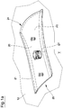
- the external element 21 has a shape tapered in width, at least along a portion of its longitudinal extension.
- the width of such portion of the external element 21 decreases in a rear direction, i.e. in the direction of the back side of the box 1 (see figure 3 ).
- the external element 21 preferably includes a first front end 22 (relative to the orientation of the box 1), wherein it exhibits the major width thereof, thereby defining a passage for the inlet of air flow.
- the width of the external element 21 becomes narrower at least along a longitudinal portion, substantially up to a median zone and it may possibly, but not necessarily, widen along a next portion which comprises the rear end 23.
- the reduced section portion ST of the first conduit 20 may be defined by the presence of an obstructive element 31, whose additional features are more fully described here below, which obstructive element 31 is placed internally the first conduit 20, thereby defining a reduced light portion.
- the above-mentioned first conduit 20 includes at least one longitudinal portion with reduced cross-section ST, thereby defining a narrowing for the passage of the channeled air flow.
- this reduced section portion ST may exhibit a variable and non-constant section, and that in other words, it is a longitudinal portion along which the amplitude of the light of the conduit decreases.
- the conduit Upstream of this reduced section portion ST (or second portion), the conduit includes a portion with a larger section PT (or first portion), with a funnel-like development preferably tapered inwardly.
- upstream is defined in relation to the air flow direction.
- reduced section portion ST By the term “reduced section portion ST” herein utilized, it is meant that the section of this portion is smaller than that of a different portion of the conduit and vice versa with reference to the portion with larger section PT.
- the second portion ST is narrower than the first portion PT arranged upstream.
- Such length portions of the first conduit 20 do not necessarily exhibit a different thickness, i.e., the vertical dimensions thereof may not differ significantly from one another.
- the second portion ST may be thinner.
- the first and second PT, ST portions can be positioned relative thereto, as shown schematically in Figure 3 .
- the Venturi device 2 of the invention includes a communication path P between the internal volume V of the box 1 and a suction portion of the first conduit 20 which includes (or corresponds) to the already mentioned reduced section portion ST.
- the path P starts from inside the box 1 (i.e. from the inner side of the cover 12), and then reaches the portion of the Venturi device 2 where pressure's decrease is generated.
- the air flows outside, through the rear inlet 25 of the first conduit 20 by passing through the rear end 23 of the external element 21.
- air suction from the inside of the box 1, may also help to decrease internal temperature.
- the Venturi device 2 includes an internal element 31, 32, comprising a second conduit 35, 36, 37, wherein said communication path P is defined, which extends between a first inlet 33 located within said internal volume V, and a second inlet 34 arranged in said suction portion (see Figure 5 ).
- This internal element 31, 32 is placed relative to a through hole 120 formed on the cover 12 of the box 1 (see figure 2 ).
- this internal element 31, 32 may comprise a first member 31, which is preferably a sleeve closed at the top and open at the bottom thereof, and realized, by way of example, in a single piece with the external element 21, which may identify aforementioned obstructive element that helps to decrease reduction in the amount of light of the main conduit (see Figures 2 and 3 ).
- the second inlet 34 of the second conduit may be defined by a through hole 37 formed transversely to the walls of the first member 31.
- such a through hole 37 is facing toward the rear of the Venturi device 2 (and therefore of the box 1), i.e., towards the outlet 25 of the first conduit 20 (as shown in Figures 4 and 5 ).
- the aforementioned second inlet 34 may be located in the reduced section portion ST of the first conduit 20, or also downstream thereof, where pressure is however lower than that in the larger section portion located upstream.
- a second member 32 can be associated to the first member 31, for example via a rotatable coupling, according to the configuration shown in Figure 5 .
- Such second member 32 is provided for allowing alternately opening and obstruction of the communication path P between the internal volume V and the first conduit 20, on user's command.
- the second member 32 may conform a shutter 320, shown in Figure 2 as a wall with cylindrical development, which is so dimensioned as to be able to completely close the through hole of the first member 31; the shutter 320 is further suitable for being moved, by way of example, along a cylindrical surface, so as to allow passage of air.
- the user may decide whether to operate the depression effect of the inventive device 2, if need be.
- prongs 38 being inferiorly formed in the second member 32 and easily accessible when the cover 12 is open.
- the second member 32 has preferably a through hole 35 which is coaxial, or otherwise in communication with the internal space 36 of the first member 31.
- first inlet 33 of the second conduit 35, 36, 37 is defined by the through hole of the second member 32.
- suitable sealing means may be provided, which are for example realized by means of a ring 41 provided with an annular seat so as to accommodate an O-ring 42, which is so positioned as to circumscribe the internal element 31, 32, preferably on the upper side of the cover 12.
- Removable fastening means such as screw means, may be provided for easy assembly (and disassembly) of the Venturi device 2 herein described.
- aforesaid external element 21 may conform inferiorly one or more tangs 51 being internally threaded and arranged coaxial to small through holes 52 formed within the cover 12, wherein fixing screws 53 can be inserted, as shown by way of example in Figure 2 .
Landscapes
- Engineering & Computer Science (AREA)
- Mechanical Engineering (AREA)
- Body Structure For Vehicles (AREA)
- Fittings On The Vehicle Exterior For Carrying Loads, And Devices For Holding Or Mounting Articles (AREA)
Priority Applications (1)
| Application Number | Priority Date | Filing Date | Title |
|---|---|---|---|
| PL15185049T PL2995503T3 (pl) | 2014-09-15 | 2015-09-14 | Box dachowy |
Applications Claiming Priority (1)
| Application Number | Priority Date | Filing Date | Title |
|---|---|---|---|
| ITMO20140258 | 2014-09-15 |
Publications (2)
| Publication Number | Publication Date |
|---|---|
| EP2995503A1 EP2995503A1 (en) | 2016-03-16 |
| EP2995503B1 true EP2995503B1 (en) | 2018-01-03 |
Family
ID=51799215
Family Applications (1)
| Application Number | Title | Priority Date | Filing Date |
|---|---|---|---|
| EP15185049.2A Not-in-force EP2995503B1 (en) | 2014-09-15 | 2015-09-14 | A roof box |
Country Status (2)
| Country | Link |
|---|---|
| EP (1) | EP2995503B1 (pl) |
| PL (1) | PL2995503T3 (pl) |
Families Citing this family (1)
| Publication number | Priority date | Publication date | Assignee | Title |
|---|---|---|---|---|
| EP3831658B1 (en) | 2019-12-04 | 2022-03-02 | Thule Sweden AB | Cargo carrier for a vehicle |
Family Cites Families (5)
| Publication number | Priority date | Publication date | Assignee | Title |
|---|---|---|---|---|
| US1665358A (en) * | 1927-03-30 | 1928-04-10 | American Car | Baggage rack for motor vehicles |
| DE19524976C1 (de) * | 1995-07-08 | 1997-01-09 | Jetbag Gmbh | Dachkoffer mit Belüftung |
| US20050194414A1 (en) * | 2004-03-05 | 2005-09-08 | Lynch Richard Q. | Cargo container |
| DE202013012349U1 (de) * | 2012-09-11 | 2016-06-06 | Thule Sweden Ab | Ladungsbehältnis mit aerodynamisch strukturierter Oberfläche |
| US9150158B2 (en) * | 2012-10-10 | 2015-10-06 | Braden A. Reiber | Ventilated vehicle roof rack carrier |
-
2015
- 2015-09-14 EP EP15185049.2A patent/EP2995503B1/en not_active Not-in-force
- 2015-09-14 PL PL15185049T patent/PL2995503T3/pl unknown
Non-Patent Citations (1)
| Title |
|---|
| None * |
Also Published As
| Publication number | Publication date |
|---|---|
| PL2995503T3 (pl) | 2018-06-29 |
| EP2995503A1 (en) | 2016-03-16 |
Similar Documents
| Publication | Publication Date | Title |
|---|---|---|
| EP3044077B1 (fr) | Becquet pour hayon de véhicule automobile | |
| US11247537B2 (en) | Positive pressure vent for a vehicle | |
| US6264354B1 (en) | Supplemental automotive lighting | |
| US8172314B2 (en) | Covering part | |
| JP2016144976A (ja) | 車両の排水構造 | |
| JP6428809B2 (ja) | 車体後部構造 | |
| EP2995503B1 (en) | A roof box | |
| FR3042259A1 (fr) | Conduit d'air de refroidissement pour projecteur de vehicule automobile | |
| CN105711654A (zh) | 用于车轮罩排风装置的导气装置 | |
| EP3144583B1 (fr) | Projecteur de véhicule à système d aération | |
| US10525818B2 (en) | Rear spoiler arrangement for a motor vehicle | |
| CA2489717A1 (fr) | Drain notamment pour mat support de reacteur | |
| KR100715898B1 (ko) | 길이 조절이 가능한 차량용 에어컨 필터 하우징 | |
| CN101111425B (zh) | 用于摩托车的行李容器 | |
| US10232693B1 (en) | Water management for a vehicle | |
| FR3092037A1 (fr) | Prise d’entrée d’air équipée d’un déflecteur pour un groupe climatiseur de véhicule automobile | |
| US8585126B1 (en) | Vehicle drain hole plug | |
| US20110169297A1 (en) | Vehicle door systems | |
| CN206914299U (zh) | 车窗清洁系统以及包括该车窗清洁系统的车辆 | |
| ES2834150A1 (es) | Vehiculo que comprende un sistema de reduccion de la resistencia aerodinamica mejorado | |
| EP2736749B1 (fr) | Cloison anti-recyclage d'un vehicule automobile. | |
| KR200202459Y1 (ko) | 자동차의 트렁크 리드 가니쉬 설치구조 | |
| JP5754629B2 (ja) | 車両の後部構造 | |
| JP2015104990A (ja) | 自動車の後部車体構造 | |
| US9976756B2 (en) | Radiator brackets for use in mounting a radiator underneath a window |
Legal Events
| Date | Code | Title | Description |
|---|---|---|---|
| PUAI | Public reference made under article 153(3) epc to a published international application that has entered the european phase |
Free format text: ORIGINAL CODE: 0009012 |
|
| AK | Designated contracting states |
Kind code of ref document: A1 Designated state(s): AL AT BE BG CH CY CZ DE DK EE ES FI FR GB GR HR HU IE IS IT LI LT LU LV MC MK MT NL NO PL PT RO RS SE SI SK SM TR |
|
| AX | Request for extension of the european patent |
Extension state: BA ME |
|
| 17P | Request for examination filed |
Effective date: 20160906 |
|
| RBV | Designated contracting states (corrected) |
Designated state(s): AL AT BE BG CH CY CZ DE DK EE ES FI FR GB GR HR HU IE IS IT LI LT LU LV MC MK MT NL NO PL PT RO RS SE SI SK SM TR |
|
| 17Q | First examination report despatched |
Effective date: 20170517 |
|
| GRAP | Despatch of communication of intention to grant a patent |
Free format text: ORIGINAL CODE: EPIDOSNIGR1 |
|
| INTG | Intention to grant announced |
Effective date: 20171012 |
|
| GRAS | Grant fee paid |
Free format text: ORIGINAL CODE: EPIDOSNIGR3 |
|
| GRAA | (expected) grant |
Free format text: ORIGINAL CODE: 0009210 |
|
| AK | Designated contracting states |
Kind code of ref document: B1 Designated state(s): AL AT BE BG CH CY CZ DE DK EE ES FI FR GB GR HR HU IE IS IT LI LT LU LV MC MK MT NL NO PL PT RO RS SE SI SK SM TR |
|
| REG | Reference to a national code |
Ref country code: GB Ref legal event code: FG4D |
|
| REG | Reference to a national code |
Ref country code: CH Ref legal event code: EP Ref country code: AT Ref legal event code: REF Ref document number: 959914 Country of ref document: AT Kind code of ref document: T Effective date: 20180115 |
|
| REG | Reference to a national code |
Ref country code: IE Ref legal event code: FG4D |
|
| REG | Reference to a national code |
Ref country code: DE Ref legal event code: R096 Ref document number: 602015007132 Country of ref document: DE |
|
| REG | Reference to a national code |
Ref country code: NL Ref legal event code: MP Effective date: 20180103 |
|
| REG | Reference to a national code |
Ref country code: LT Ref legal event code: MG4D |
|
| REG | Reference to a national code |
Ref country code: AT Ref legal event code: MK05 Ref document number: 959914 Country of ref document: AT Kind code of ref document: T Effective date: 20180103 |
|
| PG25 | Lapsed in a contracting state [announced via postgrant information from national office to epo] |
Ref country code: NL Free format text: LAPSE BECAUSE OF FAILURE TO SUBMIT A TRANSLATION OF THE DESCRIPTION OR TO PAY THE FEE WITHIN THE PRESCRIBED TIME-LIMIT Effective date: 20180103 |
|
| PG25 | Lapsed in a contracting state [announced via postgrant information from national office to epo] |
Ref country code: ES Free format text: LAPSE BECAUSE OF FAILURE TO SUBMIT A TRANSLATION OF THE DESCRIPTION OR TO PAY THE FEE WITHIN THE PRESCRIBED TIME-LIMIT Effective date: 20180103 Ref country code: CY Free format text: LAPSE BECAUSE OF FAILURE TO SUBMIT A TRANSLATION OF THE DESCRIPTION OR TO PAY THE FEE WITHIN THE PRESCRIBED TIME-LIMIT Effective date: 20180103 Ref country code: FI Free format text: LAPSE BECAUSE OF FAILURE TO SUBMIT A TRANSLATION OF THE DESCRIPTION OR TO PAY THE FEE WITHIN THE PRESCRIBED TIME-LIMIT Effective date: 20180103 Ref country code: LT Free format text: LAPSE BECAUSE OF FAILURE TO SUBMIT A TRANSLATION OF THE DESCRIPTION OR TO PAY THE FEE WITHIN THE PRESCRIBED TIME-LIMIT Effective date: 20180103 Ref country code: HR Free format text: LAPSE BECAUSE OF FAILURE TO SUBMIT A TRANSLATION OF THE DESCRIPTION OR TO PAY THE FEE WITHIN THE PRESCRIBED TIME-LIMIT Effective date: 20180103 Ref country code: NO Free format text: LAPSE BECAUSE OF FAILURE TO SUBMIT A TRANSLATION OF THE DESCRIPTION OR TO PAY THE FEE WITHIN THE PRESCRIBED TIME-LIMIT Effective date: 20180403 |
|
| PG25 | Lapsed in a contracting state [announced via postgrant information from national office to epo] |
Ref country code: AT Free format text: LAPSE BECAUSE OF FAILURE TO SUBMIT A TRANSLATION OF THE DESCRIPTION OR TO PAY THE FEE WITHIN THE PRESCRIBED TIME-LIMIT Effective date: 20180103 Ref country code: BG Free format text: LAPSE BECAUSE OF FAILURE TO SUBMIT A TRANSLATION OF THE DESCRIPTION OR TO PAY THE FEE WITHIN THE PRESCRIBED TIME-LIMIT Effective date: 20180403 Ref country code: RS Free format text: LAPSE BECAUSE OF FAILURE TO SUBMIT A TRANSLATION OF THE DESCRIPTION OR TO PAY THE FEE WITHIN THE PRESCRIBED TIME-LIMIT Effective date: 20180103 Ref country code: LV Free format text: LAPSE BECAUSE OF FAILURE TO SUBMIT A TRANSLATION OF THE DESCRIPTION OR TO PAY THE FEE WITHIN THE PRESCRIBED TIME-LIMIT Effective date: 20180103 Ref country code: SE Free format text: LAPSE BECAUSE OF FAILURE TO SUBMIT A TRANSLATION OF THE DESCRIPTION OR TO PAY THE FEE WITHIN THE PRESCRIBED TIME-LIMIT Effective date: 20180103 Ref country code: GR Free format text: LAPSE BECAUSE OF FAILURE TO SUBMIT A TRANSLATION OF THE DESCRIPTION OR TO PAY THE FEE WITHIN THE PRESCRIBED TIME-LIMIT Effective date: 20180404 Ref country code: IS Free format text: LAPSE BECAUSE OF FAILURE TO SUBMIT A TRANSLATION OF THE DESCRIPTION OR TO PAY THE FEE WITHIN THE PRESCRIBED TIME-LIMIT Effective date: 20180503 |
|
| REG | Reference to a national code |
Ref country code: FR Ref legal event code: PLFP Year of fee payment: 4 |
|
| REG | Reference to a national code |
Ref country code: DE Ref legal event code: R097 Ref document number: 602015007132 Country of ref document: DE |
|
| PG25 | Lapsed in a contracting state [announced via postgrant information from national office to epo] |
Ref country code: RO Free format text: LAPSE BECAUSE OF FAILURE TO SUBMIT A TRANSLATION OF THE DESCRIPTION OR TO PAY THE FEE WITHIN THE PRESCRIBED TIME-LIMIT Effective date: 20180103 Ref country code: AL Free format text: LAPSE BECAUSE OF FAILURE TO SUBMIT A TRANSLATION OF THE DESCRIPTION OR TO PAY THE FEE WITHIN THE PRESCRIBED TIME-LIMIT Effective date: 20180103 Ref country code: EE Free format text: LAPSE BECAUSE OF FAILURE TO SUBMIT A TRANSLATION OF THE DESCRIPTION OR TO PAY THE FEE WITHIN THE PRESCRIBED TIME-LIMIT Effective date: 20180103 |
|
| PLBE | No opposition filed within time limit |
Free format text: ORIGINAL CODE: 0009261 |
|
| STAA | Information on the status of an ep patent application or granted ep patent |
Free format text: STATUS: NO OPPOSITION FILED WITHIN TIME LIMIT |
|
| PG25 | Lapsed in a contracting state [announced via postgrant information from national office to epo] |
Ref country code: DK Free format text: LAPSE BECAUSE OF FAILURE TO SUBMIT A TRANSLATION OF THE DESCRIPTION OR TO PAY THE FEE WITHIN THE PRESCRIBED TIME-LIMIT Effective date: 20180103 Ref country code: SM Free format text: LAPSE BECAUSE OF FAILURE TO SUBMIT A TRANSLATION OF THE DESCRIPTION OR TO PAY THE FEE WITHIN THE PRESCRIBED TIME-LIMIT Effective date: 20180103 Ref country code: SK Free format text: LAPSE BECAUSE OF FAILURE TO SUBMIT A TRANSLATION OF THE DESCRIPTION OR TO PAY THE FEE WITHIN THE PRESCRIBED TIME-LIMIT Effective date: 20180103 |
|
| 26N | No opposition filed |
Effective date: 20181005 |
|
| PG25 | Lapsed in a contracting state [announced via postgrant information from national office to epo] |
Ref country code: SI Free format text: LAPSE BECAUSE OF FAILURE TO SUBMIT A TRANSLATION OF THE DESCRIPTION OR TO PAY THE FEE WITHIN THE PRESCRIBED TIME-LIMIT Effective date: 20180103 |
|
| PG25 | Lapsed in a contracting state [announced via postgrant information from national office to epo] |
Ref country code: MC Free format text: LAPSE BECAUSE OF FAILURE TO SUBMIT A TRANSLATION OF THE DESCRIPTION OR TO PAY THE FEE WITHIN THE PRESCRIBED TIME-LIMIT Effective date: 20180103 |
|
| REG | Reference to a national code |
Ref country code: CH Ref legal event code: PL |
|
| REG | Reference to a national code |
Ref country code: BE Ref legal event code: MM Effective date: 20180930 |
|
| REG | Reference to a national code |
Ref country code: IE Ref legal event code: MM4A |
|
| PG25 | Lapsed in a contracting state [announced via postgrant information from national office to epo] |
Ref country code: LU Free format text: LAPSE BECAUSE OF NON-PAYMENT OF DUE FEES Effective date: 20180914 |
|
| PG25 | Lapsed in a contracting state [announced via postgrant information from national office to epo] |
Ref country code: IE Free format text: LAPSE BECAUSE OF NON-PAYMENT OF DUE FEES Effective date: 20180914 |
|
| PG25 | Lapsed in a contracting state [announced via postgrant information from national office to epo] |
Ref country code: BE Free format text: LAPSE BECAUSE OF NON-PAYMENT OF DUE FEES Effective date: 20180930 Ref country code: LI Free format text: LAPSE BECAUSE OF NON-PAYMENT OF DUE FEES Effective date: 20180930 Ref country code: CH Free format text: LAPSE BECAUSE OF NON-PAYMENT OF DUE FEES Effective date: 20180930 |
|
| PGFP | Annual fee paid to national office [announced via postgrant information from national office to epo] |
Ref country code: CZ Payment date: 20190911 Year of fee payment: 5 |
|
| PGFP | Annual fee paid to national office [announced via postgrant information from national office to epo] |
Ref country code: PL Payment date: 20190904 Year of fee payment: 5 |
|
| PGFP | Annual fee paid to national office [announced via postgrant information from national office to epo] |
Ref country code: GB Payment date: 20190930 Year of fee payment: 5 |
|
| PG25 | Lapsed in a contracting state [announced via postgrant information from national office to epo] |
Ref country code: MT Free format text: LAPSE BECAUSE OF NON-PAYMENT OF DUE FEES Effective date: 20180914 |
|
| PG25 | Lapsed in a contracting state [announced via postgrant information from national office to epo] |
Ref country code: TR Free format text: LAPSE BECAUSE OF FAILURE TO SUBMIT A TRANSLATION OF THE DESCRIPTION OR TO PAY THE FEE WITHIN THE PRESCRIBED TIME-LIMIT Effective date: 20180103 |
|
| PG25 | Lapsed in a contracting state [announced via postgrant information from national office to epo] |
Ref country code: PT Free format text: LAPSE BECAUSE OF FAILURE TO SUBMIT A TRANSLATION OF THE DESCRIPTION OR TO PAY THE FEE WITHIN THE PRESCRIBED TIME-LIMIT Effective date: 20180103 |
|
| PG25 | Lapsed in a contracting state [announced via postgrant information from national office to epo] |
Ref country code: HU Free format text: LAPSE BECAUSE OF FAILURE TO SUBMIT A TRANSLATION OF THE DESCRIPTION OR TO PAY THE FEE WITHIN THE PRESCRIBED TIME-LIMIT; INVALID AB INITIO Effective date: 20150914 Ref country code: MK Free format text: LAPSE BECAUSE OF NON-PAYMENT OF DUE FEES Effective date: 20180103 |
|
| PG25 | Lapsed in a contracting state [announced via postgrant information from national office to epo] |
Ref country code: CZ Free format text: LAPSE BECAUSE OF NON-PAYMENT OF DUE FEES Effective date: 20200914 |
|
| GBPC | Gb: european patent ceased through non-payment of renewal fee |
Effective date: 20200914 |
|
| PG25 | Lapsed in a contracting state [announced via postgrant information from national office to epo] |
Ref country code: GB Free format text: LAPSE BECAUSE OF NON-PAYMENT OF DUE FEES Effective date: 20200914 |
|
| P01 | Opt-out of the competence of the unified patent court (upc) registered |
Effective date: 20230523 |
|
| PG25 | Lapsed in a contracting state [announced via postgrant information from national office to epo] |
Ref country code: PL Free format text: LAPSE BECAUSE OF NON-PAYMENT OF DUE FEES Effective date: 20200914 |
|
| PGFP | Annual fee paid to national office [announced via postgrant information from national office to epo] |
Ref country code: FR Payment date: 20230926 Year of fee payment: 9 Ref country code: DE Payment date: 20230928 Year of fee payment: 9 |
|
| PGFP | Annual fee paid to national office [announced via postgrant information from national office to epo] |
Ref country code: IT Payment date: 20230927 Year of fee payment: 9 |
|
| REG | Reference to a national code |
Ref country code: DE Ref legal event code: R119 Ref document number: 602015007132 Country of ref document: DE |
|
| PG25 | Lapsed in a contracting state [announced via postgrant information from national office to epo] |
Ref country code: DE Free format text: LAPSE BECAUSE OF NON-PAYMENT OF DUE FEES Effective date: 20250401 |
|
| PG25 | Lapsed in a contracting state [announced via postgrant information from national office to epo] |
Ref country code: IT Free format text: LAPSE BECAUSE OF NON-PAYMENT OF DUE FEES Effective date: 20240914 |
|
| PG25 | Lapsed in a contracting state [announced via postgrant information from national office to epo] |
Ref country code: FR Free format text: LAPSE BECAUSE OF NON-PAYMENT OF DUE FEES Effective date: 20240930 |