EP2995470A1 - Alésage de roulement de moyeu de roue - Google Patents
Alésage de roulement de moyeu de roue Download PDFInfo
- Publication number
- EP2995470A1 EP2995470A1 EP15177412.2A EP15177412A EP2995470A1 EP 2995470 A1 EP2995470 A1 EP 2995470A1 EP 15177412 A EP15177412 A EP 15177412A EP 2995470 A1 EP2995470 A1 EP 2995470A1
- Authority
- EP
- European Patent Office
- Prior art keywords
- hub
- bearing
- axle
- reaction force
- assembly
- Prior art date
- Legal status (The legal status is an assumption and is not a legal conclusion. Google has not performed a legal analysis and makes no representation as to the accuracy of the status listed.)
- Granted
Links
- 238000006243 chemical reaction Methods 0.000 claims abstract description 86
- 238000000034 method Methods 0.000 claims description 24
- 125000006850 spacer group Chemical group 0.000 claims description 22
- 150000001875 compounds Chemical class 0.000 claims description 15
- 238000005482 strain hardening Methods 0.000 claims description 10
- 239000000463 material Substances 0.000 claims description 8
- 238000005266 casting Methods 0.000 claims description 3
- 238000005520 cutting process Methods 0.000 claims description 3
- 238000009826 distribution Methods 0.000 claims description 3
- 238000009760 electrical discharge machining Methods 0.000 claims description 3
- 238000005242 forging Methods 0.000 claims description 3
- 238000000227 grinding Methods 0.000 claims description 3
- 238000003801 milling Methods 0.000 claims description 3
- 238000000465 moulding Methods 0.000 claims description 3
- 238000007514 turning Methods 0.000 claims description 3
- 230000000712 assembly Effects 0.000 description 12
- 238000000429 assembly Methods 0.000 description 12
- 230000008569 process Effects 0.000 description 5
- 229910052782 aluminium Inorganic materials 0.000 description 3
- XAGFODPZIPBFFR-UHFFFAOYSA-N aluminium Chemical compound [Al] XAGFODPZIPBFFR-UHFFFAOYSA-N 0.000 description 3
- 229910000838 Al alloy Inorganic materials 0.000 description 2
- 229910000831 Steel Inorganic materials 0.000 description 2
- 238000005452 bending Methods 0.000 description 2
- 230000008901 benefit Effects 0.000 description 2
- 230000003993 interaction Effects 0.000 description 2
- 239000010959 steel Substances 0.000 description 2
- -1 but not limited to Substances 0.000 description 1
- 238000012790 confirmation Methods 0.000 description 1
- 230000000694 effects Effects 0.000 description 1
- 210000003746 feather Anatomy 0.000 description 1
- 238000012423 maintenance Methods 0.000 description 1
- 238000004519 manufacturing process Methods 0.000 description 1
- 230000007246 mechanism Effects 0.000 description 1
- 229910052751 metal Inorganic materials 0.000 description 1
- 239000002184 metal Substances 0.000 description 1
- 230000008439 repair process Effects 0.000 description 1
- 230000000717 retained effect Effects 0.000 description 1
- 238000010008 shearing Methods 0.000 description 1
- 238000005480 shot peening Methods 0.000 description 1
- 239000011343 solid material Substances 0.000 description 1
- 230000007704 transition Effects 0.000 description 1
Images


Classifications
-
- B—PERFORMING OPERATIONS; TRANSPORTING
- B60—VEHICLES IN GENERAL
- B60B—VEHICLE WHEELS; CASTORS; AXLES FOR WHEELS OR CASTORS; INCREASING WHEEL ADHESION
- B60B27/00—Hubs
- B60B27/001—Hubs with roller-bearings
-
- B—PERFORMING OPERATIONS; TRANSPORTING
- B60—VEHICLES IN GENERAL
- B60B—VEHICLE WHEELS; CASTORS; AXLES FOR WHEELS OR CASTORS; INCREASING WHEEL ADHESION
- B60B27/00—Hubs
-
- B—PERFORMING OPERATIONS; TRANSPORTING
- B60—VEHICLES IN GENERAL
- B60B—VEHICLE WHEELS; CASTORS; AXLES FOR WHEELS OR CASTORS; INCREASING WHEEL ADHESION
- B60B27/00—Hubs
- B60B27/0078—Hubs characterised by the fixation of bearings
-
- B—PERFORMING OPERATIONS; TRANSPORTING
- B60—VEHICLES IN GENERAL
- B60B—VEHICLE WHEELS; CASTORS; AXLES FOR WHEELS OR CASTORS; INCREASING WHEEL ADHESION
- B60B27/00—Hubs
- B60B27/02—Hubs adapted to be rotatably arranged on axle
-
- B—PERFORMING OPERATIONS; TRANSPORTING
- B64—AIRCRAFT; AVIATION; COSMONAUTICS
- B64C—AEROPLANES; HELICOPTERS
- B64C25/00—Alighting gear
- B64C25/32—Alighting gear characterised by elements which contact the ground or similar surface
- B64C25/34—Alighting gear characterised by elements which contact the ground or similar surface wheeled type, e.g. multi-wheeled bogies
- B64C25/36—Arrangements or adaptations of wheels, tyres or axles in general
-
- F—MECHANICAL ENGINEERING; LIGHTING; HEATING; WEAPONS; BLASTING
- F16—ENGINEERING ELEMENTS AND UNITS; GENERAL MEASURES FOR PRODUCING AND MAINTAINING EFFECTIVE FUNCTIONING OF MACHINES OR INSTALLATIONS; THERMAL INSULATION IN GENERAL
- F16C—SHAFTS; FLEXIBLE SHAFTS; ELEMENTS OR CRANKSHAFT MECHANISMS; ROTARY BODIES OTHER THAN GEARING ELEMENTS; BEARINGS
- F16C35/00—Rigid support of bearing units; Housings, e.g. caps, covers
- F16C35/04—Rigid support of bearing units; Housings, e.g. caps, covers in the case of ball or roller bearings
- F16C35/06—Mounting or dismounting of ball or roller bearings; Fixing them onto shaft or in housing
- F16C35/067—Fixing them in a housing
-
- B—PERFORMING OPERATIONS; TRANSPORTING
- B60—VEHICLES IN GENERAL
- B60B—VEHICLE WHEELS; CASTORS; AXLES FOR WHEELS OR CASTORS; INCREASING WHEEL ADHESION
- B60B21/00—Rims
- B60B21/10—Rims characterised by the form of tyre-seat or flange, e.g. corrugated
- B60B21/104—Rims characterised by the form of tyre-seat or flange, e.g. corrugated the shape of flanges
-
- B—PERFORMING OPERATIONS; TRANSPORTING
- B60—VEHICLES IN GENERAL
- B60B—VEHICLE WHEELS; CASTORS; AXLES FOR WHEELS OR CASTORS; INCREASING WHEEL ADHESION
- B60B2310/00—Manufacturing methods
- B60B2310/20—Shaping
- B60B2310/202—Shaping by casting
-
- B—PERFORMING OPERATIONS; TRANSPORTING
- B60—VEHICLES IN GENERAL
- B60B—VEHICLE WHEELS; CASTORS; AXLES FOR WHEELS OR CASTORS; INCREASING WHEEL ADHESION
- B60B2310/00—Manufacturing methods
- B60B2310/20—Shaping
- B60B2310/208—Shaping by forging
-
- B—PERFORMING OPERATIONS; TRANSPORTING
- B60—VEHICLES IN GENERAL
- B60B—VEHICLE WHEELS; CASTORS; AXLES FOR WHEELS OR CASTORS; INCREASING WHEEL ADHESION
- B60B2310/00—Manufacturing methods
- B60B2310/20—Shaping
- B60B2310/226—Shaping by cutting
-
- B—PERFORMING OPERATIONS; TRANSPORTING
- B60—VEHICLES IN GENERAL
- B60B—VEHICLE WHEELS; CASTORS; AXLES FOR WHEELS OR CASTORS; INCREASING WHEEL ADHESION
- B60B2310/00—Manufacturing methods
- B60B2310/20—Shaping
- B60B2310/228—Shaping by machining
-
- B—PERFORMING OPERATIONS; TRANSPORTING
- B60—VEHICLES IN GENERAL
- B60B—VEHICLE WHEELS; CASTORS; AXLES FOR WHEELS OR CASTORS; INCREASING WHEEL ADHESION
- B60B2310/00—Manufacturing methods
- B60B2310/20—Shaping
- B60B2310/231—Shaping by turning
-
- B—PERFORMING OPERATIONS; TRANSPORTING
- B60—VEHICLES IN GENERAL
- B60B—VEHICLE WHEELS; CASTORS; AXLES FOR WHEELS OR CASTORS; INCREASING WHEEL ADHESION
- B60B2310/00—Manufacturing methods
- B60B2310/20—Shaping
- B60B2310/232—Shaping by milling
-
- B—PERFORMING OPERATIONS; TRANSPORTING
- B60—VEHICLES IN GENERAL
- B60B—VEHICLE WHEELS; CASTORS; AXLES FOR WHEELS OR CASTORS; INCREASING WHEEL ADHESION
- B60B2310/00—Manufacturing methods
- B60B2310/20—Shaping
- B60B2310/234—Shaping by grinding
-
- B—PERFORMING OPERATIONS; TRANSPORTING
- B60—VEHICLES IN GENERAL
- B60B—VEHICLE WHEELS; CASTORS; AXLES FOR WHEELS OR CASTORS; INCREASING WHEEL ADHESION
- B60B2360/00—Materials; Physical forms thereof
- B60B2360/10—Metallic materials
- B60B2360/102—Steel
-
- B—PERFORMING OPERATIONS; TRANSPORTING
- B60—VEHICLES IN GENERAL
- B60B—VEHICLE WHEELS; CASTORS; AXLES FOR WHEELS OR CASTORS; INCREASING WHEEL ADHESION
- B60B2360/00—Materials; Physical forms thereof
- B60B2360/10—Metallic materials
- B60B2360/104—Aluminum
-
- B—PERFORMING OPERATIONS; TRANSPORTING
- B60—VEHICLES IN GENERAL
- B60B—VEHICLE WHEELS; CASTORS; AXLES FOR WHEELS OR CASTORS; INCREASING WHEEL ADHESION
- B60B2380/00—Bearings
- B60B2380/10—Type
- B60B2380/14—Roller bearings
-
- B—PERFORMING OPERATIONS; TRANSPORTING
- B60—VEHICLES IN GENERAL
- B60B—VEHICLE WHEELS; CASTORS; AXLES FOR WHEELS OR CASTORS; INCREASING WHEEL ADHESION
- B60B2380/00—Bearings
- B60B2380/70—Arrangements
-
- B—PERFORMING OPERATIONS; TRANSPORTING
- B60—VEHICLES IN GENERAL
- B60B—VEHICLE WHEELS; CASTORS; AXLES FOR WHEELS OR CASTORS; INCREASING WHEEL ADHESION
- B60B2900/00—Purpose of invention
- B60B2900/20—Avoidance of
- B60B2900/212—Damage
-
- B—PERFORMING OPERATIONS; TRANSPORTING
- B60—VEHICLES IN GENERAL
- B60B—VEHICLE WHEELS; CASTORS; AXLES FOR WHEELS OR CASTORS; INCREASING WHEEL ADHESION
- B60B2900/00—Purpose of invention
- B60B2900/30—Increase in
- B60B2900/321—Lifetime
-
- B—PERFORMING OPERATIONS; TRANSPORTING
- B60—VEHICLES IN GENERAL
- B60B—VEHICLE WHEELS; CASTORS; AXLES FOR WHEELS OR CASTORS; INCREASING WHEEL ADHESION
- B60B2900/00—Purpose of invention
- B60B2900/70—Adaptation for
- B60B2900/711—High loads, e.g. by reinforcements
-
- B—PERFORMING OPERATIONS; TRANSPORTING
- B60—VEHICLES IN GENERAL
- B60Y—INDEXING SCHEME RELATING TO ASPECTS CROSS-CUTTING VEHICLE TECHNOLOGY
- B60Y2200/00—Type of vehicle
- B60Y2200/50—Aeroplanes, Helicopters
- B60Y2200/51—Aeroplanes
-
- F—MECHANICAL ENGINEERING; LIGHTING; HEATING; WEAPONS; BLASTING
- F16—ENGINEERING ELEMENTS AND UNITS; GENERAL MEASURES FOR PRODUCING AND MAINTAINING EFFECTIVE FUNCTIONING OF MACHINES OR INSTALLATIONS; THERMAL INSULATION IN GENERAL
- F16C—SHAFTS; FLEXIBLE SHAFTS; ELEMENTS OR CRANKSHAFT MECHANISMS; ROTARY BODIES OTHER THAN GEARING ELEMENTS; BEARINGS
- F16C19/00—Bearings with rolling contact, for exclusively rotary movement
- F16C19/22—Bearings with rolling contact, for exclusively rotary movement with bearing rollers essentially of the same size in one or more circular rows, e.g. needle bearings
- F16C19/34—Bearings with rolling contact, for exclusively rotary movement with bearing rollers essentially of the same size in one or more circular rows, e.g. needle bearings for both radial and axial load
- F16C19/36—Bearings with rolling contact, for exclusively rotary movement with bearing rollers essentially of the same size in one or more circular rows, e.g. needle bearings for both radial and axial load with a single row of rollers
- F16C19/364—Bearings with rolling contact, for exclusively rotary movement with bearing rollers essentially of the same size in one or more circular rows, e.g. needle bearings for both radial and axial load with a single row of rollers with tapered rollers, i.e. rollers having essentially the shape of a truncated cone
-
- F—MECHANICAL ENGINEERING; LIGHTING; HEATING; WEAPONS; BLASTING
- F16—ENGINEERING ELEMENTS AND UNITS; GENERAL MEASURES FOR PRODUCING AND MAINTAINING EFFECTIVE FUNCTIONING OF MACHINES OR INSTALLATIONS; THERMAL INSULATION IN GENERAL
- F16C—SHAFTS; FLEXIBLE SHAFTS; ELEMENTS OR CRANKSHAFT MECHANISMS; ROTARY BODIES OTHER THAN GEARING ELEMENTS; BEARINGS
- F16C19/00—Bearings with rolling contact, for exclusively rotary movement
- F16C19/54—Systems consisting of a plurality of bearings with rolling friction
- F16C19/546—Systems with spaced apart rolling bearings including at least one angular contact bearing
- F16C19/547—Systems with spaced apart rolling bearings including at least one angular contact bearing with two angular contact rolling bearings
- F16C19/548—Systems with spaced apart rolling bearings including at least one angular contact bearing with two angular contact rolling bearings in O-arrangement
-
- F—MECHANICAL ENGINEERING; LIGHTING; HEATING; WEAPONS; BLASTING
- F16—ENGINEERING ELEMENTS AND UNITS; GENERAL MEASURES FOR PRODUCING AND MAINTAINING EFFECTIVE FUNCTIONING OF MACHINES OR INSTALLATIONS; THERMAL INSULATION IN GENERAL
- F16C—SHAFTS; FLEXIBLE SHAFTS; ELEMENTS OR CRANKSHAFT MECHANISMS; ROTARY BODIES OTHER THAN GEARING ELEMENTS; BEARINGS
- F16C2326/00—Articles relating to transporting
- F16C2326/01—Parts of vehicles in general
- F16C2326/02—Wheel hubs or castors
-
- F—MECHANICAL ENGINEERING; LIGHTING; HEATING; WEAPONS; BLASTING
- F16—ENGINEERING ELEMENTS AND UNITS; GENERAL MEASURES FOR PRODUCING AND MAINTAINING EFFECTIVE FUNCTIONING OF MACHINES OR INSTALLATIONS; THERMAL INSULATION IN GENERAL
- F16C—SHAFTS; FLEXIBLE SHAFTS; ELEMENTS OR CRANKSHAFT MECHANISMS; ROTARY BODIES OTHER THAN GEARING ELEMENTS; BEARINGS
- F16C2326/00—Articles relating to transporting
- F16C2326/43—Aeroplanes; Helicopters
-
- F—MECHANICAL ENGINEERING; LIGHTING; HEATING; WEAPONS; BLASTING
- F16—ENGINEERING ELEMENTS AND UNITS; GENERAL MEASURES FOR PRODUCING AND MAINTAINING EFFECTIVE FUNCTIONING OF MACHINES OR INSTALLATIONS; THERMAL INSULATION IN GENERAL
- F16C—SHAFTS; FLEXIBLE SHAFTS; ELEMENTS OR CRANKSHAFT MECHANISMS; ROTARY BODIES OTHER THAN GEARING ELEMENTS; BEARINGS
- F16C25/00—Bearings for exclusively rotary movement adjustable for wear or play
- F16C25/06—Ball or roller bearings
-
- F—MECHANICAL ENGINEERING; LIGHTING; HEATING; WEAPONS; BLASTING
- F16—ENGINEERING ELEMENTS AND UNITS; GENERAL MEASURES FOR PRODUCING AND MAINTAINING EFFECTIVE FUNCTIONING OF MACHINES OR INSTALLATIONS; THERMAL INSULATION IN GENERAL
- F16C—SHAFTS; FLEXIBLE SHAFTS; ELEMENTS OR CRANKSHAFT MECHANISMS; ROTARY BODIES OTHER THAN GEARING ELEMENTS; BEARINGS
- F16C35/00—Rigid support of bearing units; Housings, e.g. caps, covers
- F16C35/04—Rigid support of bearing units; Housings, e.g. caps, covers in the case of ball or roller bearings
- F16C35/06—Mounting or dismounting of ball or roller bearings; Fixing them onto shaft or in housing
- F16C35/07—Fixing them on the shaft or housing with interposition of an element
- F16C35/073—Fixing them on the shaft or housing with interposition of an element between shaft and inner race ring
Definitions
- the disclosure relates to a wheel assembly, such as for an aircraft.
- Aircraft wheel assemblies are subject to a variety of forces during aircraft operation, including, e.g., during takeoff, landing, and braking operations.
- Various mechanisms have been employed to counteract such forces on the wheel assembly and to maintain the integrity and operational characteristics of the assembly under the influence of such forces.
- the disclosure describes an vehicle wheel assembly that includes an axle, a bearing assembly, and a hub defining a bearing bore, where the bearing bore is configured such that the dynamic radial and axial thrust bearing reactions between the axle and the hub results in a first reaction force F R applied to the hub, the first reaction force F R having a radial component, and a second reaction force F N applied to the hub, the second reaction force F N having both a radial component and an axial component.
- the wheel assembly may be, for example, a wheel assembly of an aircraft.
- the configuration of the hub may help improve the performance of the assembly, e.g., compared to a hub having a convention bearing bore configuration (e.g., shape and geometry).
- the confirmation of the hub may reduce wear, improve longevity, and generally improve the so-called fatigue life of the assembly.
- the bearing bore radius may be defined by the region of the hub adjacent to the radial contact of the bearing assembly and the axial contact of a bearing spacer (also referred to as a "bearing block") of the bearing assembly to the hub.
- the disclosure is also directed to a method of forming the hub and, in some examples, the wheel assembly.
- the disclosure describes a vehicle wheel assembly comprising an axle, a bearing assembly, and a hub configured to rotate relative to the axle and defining a bearing bore, wherein the bearing assembly is positioned between the axle and the hub, and wherein the bearing bore is configured such that a reaction between the axle and the hub results in a first reaction force F R applied to the hub, the first reaction force F R having a radial component, and a second reaction force F N applied to the hub, the second reaction force F N having both a radial and an axial component.
- the disclosure describes a method comprising forming a hub defining a bearing bore, wherein the bearing bore is configured such that when the hub is mounted on an axle of a vehicle via a bearing assembly, a reaction between the axle and the hub results in a first reaction force F R applied to the hub, the first reaction force F R having a radial component, and a second reaction force F N applied to the hub, the second reaction force F N having both a radial and an axial component.
- the method further comprises cold working the bearing bore.
- the disclosure describes a method comprising positioning a bearing assembly on an axle of a vehicle wheel assembly, and mounting a hub on the axle, wherein the bearing assembly is positioned between the axle and the hub, and the hub configured to rotate relative to the axle and defines a bearing bore, and wherein the bearing bore is configured such that a reaction between the axle and the hub results in a first reaction force F R applied to the hub, the first reaction force F R having a radial component, and a second reaction force F N applied to the hub, the second reaction force F N having both a radial and an axial component.
- a wheel assembly of a vehicle such as an aircraft, includes an axle, a wheel, a hub, and a bearing assembly, which is configured to enable the aircraft wheel to rotate relative to the axle, which may be fixed to the vehicle.
- the rotation of the aircraft wheel may be referred to herein as "wheel roll.”
- the hub may define at least one bearing bore configured to engage with the bearing assembly.
- the bearing bore may, for example, define a surface with which the bearing assembly engages with the hub.
- the bearing bore may define a radius (also referred to herein as a "bearing bore radius"), which may be defined by the region adjacent to the radial contact of the bearing assembly to the hub and the region adjacent to the axial contact of a bearing spacer of the bearing assembly to the hub.
- a radius also referred to herein as a "bearing bore radius”
- the fatigue life may generally refer to the amount of time that the aircraft wheel assembly can operate in an acceptable working condition.
- General wear and tear, the amount of localized stress, as well as external factors, such as weather or exposure to elements, may affect the fatigue life of the aircraft wheel assembly.
- the wheel assembly described herein may reduce susceptibility to one or more of these factors and may generally extend the fatigue life relative to other wheel assemblies. By extending the fatigue life, the wheel assembly may require less frequent maintenance, which may include repair or replacement of one or more components of the wheel assembly, such as the hub.
- the dynamic radial and axial thrust bearing reactions into the wheel hub during wheel roll may produce relatively significant stress levels in the hub that contribute to limiting the fatigue life of a wheel assembly.
- modifying the local geometry of the bearing bore and modifying compressive residual stresses through a cold working process of the hub such as shot peen or roll burnishing of the bearing bore of the hub, may be useful for increasing the fatigue life of the wheel assembly.
- the real estate to provide the necessary bearing bore geometry to facilitate the ease of cold working can be limited, due to the limited space between the hub and the bearing assembly.
- Cold working may also be referred to as work hardening or strain hardening, and may be used to strength a metal by plastic deformation.
- the hub described herein, as well as an aircraft wheel assembly comprising the hub, is configured such that the bearing bore radius defined by the hub is configured to distribute the stresses attributable to the dynamic radial and axial thrust bearing reactions into the wheel hub during wheel roll in a manner that helps increase the fatigue life of the aircraft.
- a conventional geometric configuration of a bearing bore results in a pure radial contact surface configured to take the radial reaction force applied to the hub from the bearing assembly during wheel roll, and a vertical thrust face configured to take the axial reaction forces applied to the hub during the wheel roll.
- the bearing reactions are divided into purely separate radial and axial components.
- the bearing bore configuration disclosed herein is configured such that, instead of a pure axial reaction force applied to the hub, a reaction force with both a radial component and an axial component is applied to the hub from the bearing assembly during wheel roll.
- a radial reaction force applied to the hub from the bearing assembly during wheel roll may help control the direction and position of the reaction load, through the geometry, to minimize stress in the hub by reducing the moment caused by the reaction.
- Finite Element bases fatigue analysis has demonstrated that this bearing bore configuration may improve fatigue life in the bearing bore by more than a factor of two.
- the geometry of the bearing bore described in this disclosure may also allow for a relatively large bearing bore radius, which may further reduce the stress concentration effect on the hub.
- the larger bearing bore radius may facilitate the ease of the cold working process on the hub, and may enable the use of a roll burnishing technique, which may be relatively effective, to produce higher compressive residuals that may prolong wheel fatigue life.
- An aircraft wheel assembly including the hub with the increased bearing bore radius disclosed herein may also include a larger bearing spacer (as compared to a conventional wheel assembly that has a bearing bore radius that results in bearing reactions with separate radial and axial components) configured to engage with the hub at the bearing bore surfaces.
- the geometry between the hub at the bearing bore and the bearing block of the bearing assembly is changed along the intersection of the bearing bore and bearing block (also referred to hearing as a bearing spacer), e.g., "feathered" away, to help minimize stress peaking at the edges of contact and help direct the reaction load through a thicker section of the wheel hub.
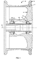
- FIG. 1 is a conceptual cross-sectional view of an example aircraft wheel assembly 10.
- Assembly 10 is a flange retained aircraft wheel assembly.
- the hub configuration described herein, however, may be applied to other types of wheel assemblies.
- wheel assembly 10 has a longitudinal axis 12 about which the assembly rotates during operation of the vehicle to which the wheel is attached.
- Wheel assembly 10 may be employed in a number of different types of vehicles, including, e.g., a number of different types of aircraft and automotive vehicles.
- Wheel assembly includes inboard annular wheel component 14 and outboard annular wheel component 16 which together support a tire (not shown) thereon.
- Outboard wheel component 16 can be axially secured to inboard wheel component 14 using any suitable technique, such as a lock ring 17.
- Inboard annular wheel component 14 includes hub 18.
- hub 18 is generally cylindrical. However, in other examples, hub 18 may assume a variety of shapes. Hub 18 may define a number of axially spaced (spaced along axis of rotation 12) annular recesses configured to receive bearing assemblies for supporting inboard wheel component 14, and thereby wheel assembly 10, for rotation on axle 20 having axis of rotation 12 as its center. The recesses may be referred to as bearing bores. Two bearing bores 22, 24, and respective bearing assemblies 26, 28 are shown in the example of FIG. 1 .
- Bearing bores 22, 24 defined by hub 18 include surfaces that interface with axle 20, e.g., via bearing assemblies 26, 28.
- bearing assemblies 26, 28 are positioned between axle 20 and the respective bearing bores 22, 24.
- the components of wheel assembly 10 may be fabricated using a number of solid material manufacturing techniques, including, e.g., forging, casting, molding, or one or more material removal processes, including, e.g., milling, turning, grinding, electrical discharge machining (EDM), or laser or torch cutting. In the latter process, the material may be removed from a starting piece of material.
- solid material manufacturing techniques including, e.g., forging, casting, molding, or one or more material removal processes, including, e.g., milling, turning, grinding, electrical discharge machining (EDM), or laser or torch cutting.
- EDM electrical discharge machining
- laser or torch cutting the material may be removed from a starting piece of material.
- Hub 18 may be subject to relatively high stresses at a region between bearing assemblies 26, 28 and hub 18. For example, during a ground operation of an aircraft including wheel assembly 10, the interaction between axle 20 and hub 18 via bearing assemblies 26, 28 may cause relatively high reaction forces to be applied to hub 18. These reaction forces may fatigue hub 18 over time. As described in further detail with respect to FIGS. 2 and 4A , bearing bores 22, 24 are configured to help minimize the fatigue of hub 18 by at least distributing the reaction forces applied to hub 18 from axle 20 (via bearing assemblies 26, 28) in a manner that helps reduce the moment caused by the forces.
- bearing bores 22, 24 are configured (e.g., the size and geometry may be selected) such that the reaction forces are distributed to relatively thick portions of hub 18 (e.g., the thickest portion of hub 18 or at least not through the thinnest portion of hub 18) in order to better direct the reaction forces to regions of hub 18 that may be better able to withstand the forces (e.g., due to the force being able to act through a relatively large distance), as compared to other, thinner regions of hub 18.
- the thickness of hub 18 may be measured, for example, from a surface of bearing bore 22 (or bearing bore 24) to an opposite surface of hub 18.
- bearing bores 22, 24 may be configured to help improve the fatigue life of hub 18, at least relative to a conventional bearing bore configuration.
- Hub 18 may be formed from any suitable material, such as, but not limited to an aluminum alloy (e.g., Aluminum 2014-T6, which is an aluminum alloy having a density of about 2.8 grams per cubic centimeter (g/cc)).
- bearing bore 22 and bearing assembly 26 for ease of description.
- FIG. 2 illustrates a zoomed-in view of a portion of aircraft wheel assembly 10 of FIG. 1 .
- Orthogonal x-y axes are shown in FIG. 2 to aid the description of the figure.
- Axis of rotation 12 extends along the x-axis.
- assembly 10 includes hub 18, axle 20, bearing bore 22, and bearing assembly 26, which engages with bearing bore 22.
- bearing assembly 26 includes axle sleeve 30, bearing cone 32, bearing roller 34, bearing cup 36, and bearing spacer 38.
- bearing assembly 26 can have another suitable configuration.
- the components of bearing assembly 26 may be formed from any suitable material, such as, but not limited to, steel or aluminum.
- axle sleeve 30, bearing cone 32, bearing roller 34, and bearing cup 36 may be formed from steel and bearing spacer 38 may be formed from aluminum.
- Axle sleeve 30 may be configured to engage with axle 20, e.g., may be in direct contact with axle 30.
- Bearing cone 32 is positioned between axle sleeve 30 and bearing roller 34 and is configured to support bearing roller 34 on axle 20.
- Bearing roller 34 is positioned between bearing cone 32 and bearing cup 36 and is configured to provide relative rotational movement between bearing cone 32 and bearing cup 36.
- Bearing spacer 38 is positioned between hub 18 and bearing cone 32, bearing roller 34, and bearing cup 36.
- axle sleeve 30, bearing cone 32, bearing roller 34, and bearing cup 36 are each axisymmetric (e.g., cylindrical).
- bearing assembly 26 can include other configurations that helps rotationally support hub 18 on axle 20, i.e., mechanically mounts hub 18 to axle 20 and allows hub 18 to rotate relative to axle 20.
- bearing assembly 26 can include a fewer or greater number of components than that shown in the example of FIG. 2 .
- bearing bore 22 defined by hub 18 may be configured such that the dynamic radial and axial thrust bearing reactions between axle 20 and hub 18 results in a first reaction force F R applied to hub 18, the first reaction force F R having a radial component, and a second reaction force F N applied to hub 18, the second reaction force F N having both a radial component and an axial component, as described in greater detail below.
- reaction force F N has both axial and radial components, which helps to direct the reaction forces to a thicker portion of hub 18 and reduces a moment arm of the force applied to hub 18.
- FIG. 3 is a conceptual cross-sectional view of a part of an example aircraft wheel assembly, and, in particular, illustrates hub 40 defining bearing bore 42 and bearing assembly 44 including bearing cup 46 and bearing spacer 48.
- bearing bore 42 has a geometry that causes the bearing reactions between hub 40 and bearing assembly 44 to be divided into a pure radial component F R at a radial contact between hub 40 and bearing cup 46, and a pure axial component F A , which is applied to a vertical thrust face 50 between bearing spacer 48 to hub 40.
- Vertical thrust face 50 may be oriented along the y-axis, and may be substantially perpendicular to an axis of rotation of hub 40. Due to these stresses, region 52 may be subject to high stresses that may lead to low fatigue life for hub 40 (e.g., may require hub 40 to be replaced relatively early). In addition, the application of the axial stress F A to a relatively thin (e.g., as shown as thickness T in FIG. 3 ) portion of hub 40 may cause shearing of hub 40.
- Vertical thrust face 50 may be a surface defined by hub 40 that extends substantially along the y-axis (e.g., along the y-axis or generally along the y-axis).
- hub 18 of assembly 10 defines bearing bore 22 having a geometry that helps distribute the stresses applied to hub 18 from axle 20 into reaction force F N ( FIG. 2 ) with both a radial component and an axial component.
- the configuration of bearing bore 22 also results in reaction force F R .
- Bearing bore 22 can be configured (e.g., by both geometry, such as a compound radius, and size) such that a centroid of reaction force F N is tailored to act at a smaller moment arm relative to a high stress location 60, as compared to bearing bore 42 shown in FIG. 3 , thus reducing a bending moment.
- bearing bore 22 may be configured such that load F N is acting at a shorter distance from region 60 than axial force F A ( FIG. 3 ), which may be subject to relatively high fatigue, to generate a smaller moment arm and generate smaller bending stresses in region 60.
- High stress location 60 e.g., a high stress point
- hub 18 of assembly 10 is configured such that the reaction forces applied to hub 18 from axle 20 do not act on any vertical faces of hub 18.
- bearing bore 22 is configured to include a curvilinear surface 39 (in cross-section), without a vertical face like vertical face 50 shown in FIG. 3 (the vertical direction being measured in the y-direction, where orthogonal x-y axes are shown in FIG. 2 for ease of description only). This may further help distribute the forces along hub 18 to improve the fatigue life of hub 18 relative to hub 40 shown in FIG. 3 .
- vertical face 50 may be planar; in contrast, in some examples, bearing bore 22 does not include any planar surfaces, but, rather, defines curve surfaces that engage with bearing assembly 26.
- bearing bore 22 of hub 18 is configured such that load having an axial component, load F N , may act through a relatively thick section of hub 18 (e.g., thicker than in the design shown in FIG. 3 and not through the thinnest section of hub 18, which may be region 19 shown in FIG. 2 ), thereby reducing the shear force applied to hub 18.
- the thickness of hub 18 may be measured in a direction from a surface of hub 18 defining bearing bore 22 to an outer surface or hub 18.
- Reducing the shear force applied to hub 18 may also help prevent shear out of hub 18 or increase the time required for shear out to occur, thereby improving fatigue life of hub 18.
- bearing spacer 38 is larger than bearing spacer 48 ( FIG. 3 ) in order to accommodate and help fill the larger bearing bore 22 that results from replacing vertical thrust face 50 with curvilinear face 39. Due to the larger bearing spacer 38, the surface area with which bearing assembly 26 contacts hub 18 (at both bearing spacer 38 and bearing cup 36) is larger than the surface area with which bearing assembly 44 contacts bearing bore 42 ( FIG. 3 ). This may help improve the fatigue life of hub 18, particularly when compared to hub 40. For example, the larger bearing spacer 38 may provide a larger surface area over which the forces may be distributed to hub 18.
- bearing bore 22 in accordance with the disclosure differs from a conventional bearing bore 42 in that the radius of bearing bore 22 is configured such that the reactions forces applied to hub 18 from axle 20 are recharacterized from a purely radial load F R and axial load F A to a radial load F R and combined normal load F N .
- bearing bore 22 does not include a constant radius of curvature in cross-section (where the cross-section is taken parallel axis of rotation 12), but, rather has a non-constant radius of curvature defined by a compound radius.
- the curvilinear cross-sectional gemoetry of bearing bore 22 may allow bearing bore 22 to have a larger compound radius compared to bearing bore of 42 of hub 40 ( FIG.
- the direction of the axial force F A previously acting on region 60 may be controlled to include both axial and radial components, as indicated by force F N , which may help direct the reaction forces to a portion of hub 18 that is relatively thick and, therefore, reduce the possibility of shear out of hub 18 due to the reaction forces.
- the fatigue life (at least in region 60) of hub 18 may increase, as compared to hub 40 defining a bearing bore 42 having a geometry that includes both pure radial load (F R ) and axial loads (F A ).
- the configuration of bearing bore 22 may reduce stress in region 60 by a factor of about three to about four.
- the effectiveness of improving fatigue life may vary with the particular aircraft wheel assembly.
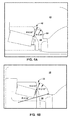
- FIGS. 4A and 4B illustrate an example of how the compound radii of bearing bore 22 may differ from the conventional bearing bore 40.
- FIG. 4A illustrates an example conventional bearing bore 40 in which radii of 0.50 inches (about 1.27 cm) and about 0.19 inches (about 0.48 cm) make up the compound radius of hub 40. Hub 40 contacts bearing spacer 48 at a vertical face 50.
- FIG. 4B illustrates an example configuration of bearing bore 22.
- Bearing bore 22 is defined by a compound radius of curvature that includes a first radius that is further from axle 20 and a second radius greater than the first radius, the second radius being closer to the axle 20 when hub 18 is mounted on axle 20.
- the centers of the first and second radii do not coincide.
- the second radius is about one-third (1/3) the first radius.
- each bearing bore 22 configuration may have a different ratio of first and second radii, which may be selected based on available real estate to work with.
- a second radius that is about 1/3 (e.g., 1/3 or nearly 1/3) of the first radius may be a starting point prior to optimizing the first and second radii using Finite Element Analysis or another force analysis technique.
- the radii of about 0.70 inches (about 1.78 centimeters (cm)) and about 2.34 inches (about 5.94 cm) make up the compound bore radius of bearing bore 22 of hub 18.
- the 0.70 inch first radius sweeps through most of the compound bore radius, with the 2.34 inch second radius at the very lower end, closer to axle 20, to define a gradual "feathering away" of the contact between hub 18 and bearing spacer 38, e.g., a gradual and smooth departure of the contact surfaces of hub 18 and bearing spacer 38.
- the radius of the compound radius of the spacer 38 is predominately 0.70 inches throughout contact with hub 18, but transitions to a 0.15 inch (0.38 cm) radius at the upper end to help "feather" the contact of the spacer 38 away from hub 18.
- radii of curvature may be used to define bearing bore 22.
- the radii of curvature may depend on the relative size of bearing bore 22, the available real estate to modify the radii of curvatures of bearing bore 22, and driving load conditions.
- bearing bore 22 may be defined and then cold worked (e.g., via shot peen or roll burnishing).
- Bearing bore 22 may be defined to have geometry such that when the hub is mounted on an axle of a vehicle via a bearing assembly, a reaction between the axle and the hub results in a first reaction force F R applied to the hub, the first reaction force F R having a radial component, and a second reaction force F N applied to the hub, the second reaction force F N having both a radial and an axial component.
- this geometry may be achieved by, for example, defining bearing bore 22 that has a curvilinear cross-sectional profile without any planar surfaces.
- the hub can be formed by, for example, at least one of forging, casting, or molding the hub from a suitable material. In other examples, forming the hub comprises at least one of milling, turning, grinding, electrical discharge machining (EDM), or laser or torch cutting the hub from a starting piece of material.
- EDM electrical discharge machining
- axle 20, bearing assembly 26, and hub 18 having the configuration described herein may be assembled together.
- the method may include positioning bearing assembly 26 on axle 20 of wheel assembly 10, and mounting hub 18 on axle 20, wherein bearing assembly 26 is positioned between axle 20 and hub 18.
- Bearing assembly 26 is configured to permit hub 18 to rotate relative to axle 20.
- mounting hub 18 on the axle comprises mounting inboard annular wheel component 14 ( FIG. 1 ) comprising hub 18 on axle 20, and the method may further comprise connecting outboard annular wheel component 16 ( FIG. 1 ) to inboard wheel component.
- Inboard annular wheel component 14 and outboard annular wheel component 16 may be configured to support a tire.
Applications Claiming Priority (2)
| Application Number | Priority Date | Filing Date | Title |
|---|---|---|---|
| US201462031052P | 2014-07-30 | 2014-07-30 | |
| US14/752,458 US10300740B2 (en) | 2014-07-30 | 2015-06-26 | Wheel hub bearing bore |
Publications (2)
| Publication Number | Publication Date |
|---|---|
| EP2995470A1 true EP2995470A1 (fr) | 2016-03-16 |
| EP2995470B1 EP2995470B1 (fr) | 2021-03-10 |
Family
ID=55179147
Family Applications (1)
| Application Number | Title | Priority Date | Filing Date |
|---|---|---|---|
| EP15177412.2A Active EP2995470B1 (fr) | 2014-07-30 | 2015-07-17 | Alésage de roulement de moyeu de roue |
Country Status (3)
| Country | Link |
|---|---|
| US (1) | US10300740B2 (fr) |
| EP (1) | EP2995470B1 (fr) |
| CN (1) | CN105317852B (fr) |
Families Citing this family (4)
| Publication number | Priority date | Publication date | Assignee | Title |
|---|---|---|---|---|
| FR3055379B1 (fr) | 2016-08-24 | 2018-08-10 | Safran Landing Systems | Roue d'aeronef a boitier a roulements separable |
| FR3056671B1 (fr) * | 2016-09-26 | 2018-10-12 | Safran Landing Systems | Procede pour equiper un tube fin d'une butee d'extremite reglable par vissage |
| CA3116483C (fr) * | 2016-12-05 | 2024-04-09 | Hendrickson Usa, L.L.C. | Moyeu pour vehicule utilitaire lourd |
| US20220111680A1 (en) * | 2020-10-09 | 2022-04-14 | Volvo Truck Corporation | Wheel end assembly for a vehicle |
Citations (5)
| Publication number | Priority date | Publication date | Assignee | Title |
|---|---|---|---|---|
| EP1122094A2 (fr) * | 2000-01-31 | 2001-08-08 | Shimano Inc. | Moyeu de bicyclette |
| US20090108667A1 (en) * | 2007-10-26 | 2009-04-30 | Textron Inc. | Molded Wheel with Integral Hub |
| EP2392478A2 (fr) * | 2010-06-01 | 2011-12-07 | Consolidated Metco, Inc. | Ensemble formant moyeu de roue |
| US20130230265A1 (en) * | 2012-03-01 | 2013-09-05 | Amsted Rail Company, Inc. | Roller bearing backing ring assembly |
| EP2749431A2 (fr) * | 2012-12-31 | 2014-07-02 | Goodrich Corporation | Ensemble de roue à double anneau de verrouillage |
Family Cites Families (37)
| Publication number | Priority date | Publication date | Assignee | Title |
|---|---|---|---|---|
| US543301A (en) * | 1895-07-23 | grant | ||
| US691922A (en) * | 1899-11-11 | 1902-01-28 | William N Whitely | Roller-bearing. |
| US992949A (en) * | 1908-08-05 | 1911-05-23 | Standard Roller Bearing Company | Annular roller-bearing. |
| US1383758A (en) * | 1919-05-26 | 1921-07-05 | Chapman Double Ball Bearing Co | Roller-bearing |
| US2052524A (en) * | 1931-01-20 | 1936-08-25 | Budd Wheel Co | Full floating axle assembly |
| US1950592A (en) * | 1932-03-10 | 1934-03-13 | Yellow Truck & Coach Mfg Co | Outer wheel bearing retention |
| US3237288A (en) * | 1964-03-18 | 1966-03-01 | Budd Co | Method and means for cold-forming wheel hubs |
| SE340577B (fr) | 1970-04-01 | 1971-11-22 | Volvo Ab | |
| US4244631A (en) * | 1979-10-09 | 1981-01-13 | Rockwell International Corporation | Hub and bearing assembly |
| SE463911B (sv) | 1989-06-12 | 1991-02-11 | Volvo Ab | Anordning foer lagring av ett hjulnav |
| JP2589926Y2 (ja) * | 1993-03-11 | 1999-02-03 | 光洋精工株式会社 | ハブユニット |
| US5862890A (en) * | 1996-01-16 | 1999-01-26 | Mcdonnell Douglas Corporation | Restrained aircraft brake apparatus |
| DE69819217T2 (de) | 1997-01-17 | 2004-08-19 | Nsk Ltd. | Wälzlagereinheit für ein Fahrzeugrad |
| US6146022A (en) | 1997-12-25 | 2000-11-14 | Ntn Corporation | Hub unit bearing for wheel |
| US6149244A (en) | 1998-05-29 | 2000-11-21 | Consolidated Metco Inc. | Wheel hub assembly and method of installing a hub on an axle |
| US6241322B1 (en) * | 1998-06-05 | 2001-06-05 | Cal M. Phillips | Quick-release bicycle axle fastener nut |
| US6244751B1 (en) | 1999-02-26 | 2001-06-12 | Temper Corporation | Adjustable spacer having a generally axially curved bearing interface portion |
| US6857786B2 (en) | 2000-02-01 | 2005-02-22 | Frank Victor Csik | Constant velocity joint integrated to wheel bearing and to axially adjustable hub |
| US6550510B2 (en) | 2001-03-16 | 2003-04-22 | Honeywell International Inc. | Optimized demountable flange and retaining ring geometry for aircraft wheels |
| US20030063827A1 (en) | 2001-10-02 | 2003-04-03 | The Timken Company | Compact hub assembly for automotive vehicles |
| US6659650B2 (en) | 2002-01-28 | 2003-12-09 | The Timken Company | Wheel bearing with improved cage |
| DE10219018B8 (de) | 2002-04-27 | 2004-10-28 | Gkn Driveline International Gmbh | Radnabeneinheit |
| US7506940B2 (en) | 2005-09-02 | 2009-03-24 | Hendrickson Usa, L.L.C. | Axle spindle and wheel end assembly |
| WO2007037477A1 (fr) | 2005-09-30 | 2007-04-05 | Ntn Corporation | Dispositif a palier pour roue |
| WO2007078616A2 (fr) | 2005-12-22 | 2007-07-12 | Timken Us Corporation | Roulement à rouleaux coniques et procédé de fabrication |
| US7369966B1 (en) | 2007-02-12 | 2008-05-06 | Honeywell International Inc. | Methods and apparatus to design a wheel of a multiple-axle vehicle |
| US7670059B2 (en) | 2007-04-16 | 2010-03-02 | The Timken Company | Vehicle corner module |
| DE102007034501A1 (de) | 2007-07-25 | 2009-01-29 | Schaeffler Kg | Wälzlager-Drehverbindung |
| DE102007059587A1 (de) * | 2007-12-11 | 2009-06-18 | Schaeffler Kg | Radlagerung eines Flugzeugfahrwerks |
| CN201380719Y (zh) * | 2009-05-04 | 2010-01-13 | 天津泰美自行车有限公司 | 电动车铝合金轮毂车轴转动结构 |
| DE102009023042A1 (de) | 2009-05-28 | 2010-07-01 | Schaeffler Technologies Gmbh & Co. Kg | Verfahren zur Ausprägung einer Strinverzahnung |
| US20110097027A1 (en) | 2009-10-26 | 2011-04-28 | Jong Soon Im | Outer ring for wheel bearing |
| DE102010038067B4 (de) | 2010-10-08 | 2014-07-17 | Wolfgang Weiss | Formschlussverbindung mit Ausgleich von Lagefehlern |
| WO2012122993A1 (fr) | 2011-03-11 | 2012-09-20 | Skf B.V. | Moyeu léger à rebord |
| DE102011078713B4 (de) * | 2011-07-06 | 2014-10-30 | Saf-Holland Gmbh | Radlageranordnung |
| WO2013029638A1 (fr) | 2011-08-29 | 2013-03-07 | Aktiebolaget Skf | Structure de roulement à billes et à rouleaux cylindriques intégrée dans un moyeu d'une roue de véhicule |
| DE102012211261B4 (de) | 2012-06-29 | 2022-09-08 | Aktiebolaget Skf | Lageranordnung |
-
2015
- 2015-06-26 US US14/752,458 patent/US10300740B2/en active Active
- 2015-07-17 EP EP15177412.2A patent/EP2995470B1/fr active Active
- 2015-07-29 CN CN201510453474.6A patent/CN105317852B/zh active Active
Patent Citations (5)
| Publication number | Priority date | Publication date | Assignee | Title |
|---|---|---|---|---|
| EP1122094A2 (fr) * | 2000-01-31 | 2001-08-08 | Shimano Inc. | Moyeu de bicyclette |
| US20090108667A1 (en) * | 2007-10-26 | 2009-04-30 | Textron Inc. | Molded Wheel with Integral Hub |
| EP2392478A2 (fr) * | 2010-06-01 | 2011-12-07 | Consolidated Metco, Inc. | Ensemble formant moyeu de roue |
| US20130230265A1 (en) * | 2012-03-01 | 2013-09-05 | Amsted Rail Company, Inc. | Roller bearing backing ring assembly |
| EP2749431A2 (fr) * | 2012-12-31 | 2014-07-02 | Goodrich Corporation | Ensemble de roue à double anneau de verrouillage |
Also Published As
| Publication number | Publication date |
|---|---|
| EP2995470B1 (fr) | 2021-03-10 |
| US20160031259A1 (en) | 2016-02-04 |
| US10300740B2 (en) | 2019-05-28 |
| CN105317852A (zh) | 2016-02-10 |
| CN105317852B (zh) | 2019-11-19 |
Similar Documents
| Publication | Publication Date | Title |
|---|---|---|
| EP2995470B1 (fr) | Alésage de roulement de moyeu de roue | |
| US8459876B2 (en) | Rolling bearing and method for the production thereof | |
| CN103143885B (zh) | 一种对开式薄壁零件的加工方法 | |
| CN101743133B (zh) | 车轮用轴承装置 | |
| US20160159392A1 (en) | Lightweight Steering Knuckle Assembly and Method of Manufacturing the Same | |
| CN101636282B (zh) | 车轮用轴承装置及其制造方法 | |
| EP3252326B1 (fr) | Roulement à rouleaux coniques | |
| JP2008173661A (ja) | ハブ輪製造用金型装置及びハブ輪製造方法 | |
| US20170157736A1 (en) | Deep rolling tool for blade fatigue life enhancement | |
| EP2052877B1 (fr) | Système de réduction de contrainte de moyeu de roue | |
| US10105799B2 (en) | Hub unit manufacturing apparatus | |
| JP2017044268A (ja) | 旋回軸受 | |
| JPS63267160A (ja) | ホイ−ルのボルト穴のナツト座加工方法 | |
| CN101954565B (zh) | 翻边轴承的更换工艺 | |
| JP5750998B2 (ja) | 段付円柱状部材の製造方法 | |
| CN110977365A (zh) | 一种超高强度不锈钢大齿圈内齿轮精密加工方法 | |
| CN210461384U (zh) | 一种带调整垫圈的特大型双列圆锥滚子回转支承 | |
| EP4022192B1 (fr) | Palier-feuille | |
| CN109365548B (zh) | 一种加固辊道剪后工件退出结构 | |
| CN104760711B (zh) | 一种卫星太阳电池阵模拟驱动装置 | |
| EP3321381B1 (fr) | Article conique traitée et procédé de traitement d'un article conique | |
| CN207195036U (zh) | 同轴度可调的发动机机匣 | |
| JP4284951B2 (ja) | 玉軸受用軌道輪の製造方法 | |
| US20220412407A1 (en) | Method for increasing the load-bearing capacity, and rolling device for hard rolling a surface-hardened rolling-bearing raceway | |
| US9902482B2 (en) | Deep rolling forming |
Legal Events
| Date | Code | Title | Description |
|---|---|---|---|
| PUAI | Public reference made under article 153(3) epc to a published international application that has entered the european phase |
Free format text: ORIGINAL CODE: 0009012 |
|
| 17P | Request for examination filed |
Effective date: 20150717 |
|
| AK | Designated contracting states |
Kind code of ref document: A1 Designated state(s): AL AT BE BG CH CY CZ DE DK EE ES FI FR GB GR HR HU IE IS IT LI LT LU LV MC MK MT NL NO PL PT RO RS SE SI SK SM TR |
|
| AX | Request for extension of the european patent |
Extension state: BA ME |
|
| STAA | Information on the status of an ep patent application or granted ep patent |
Free format text: STATUS: EXAMINATION IS IN PROGRESS |
|
| 17Q | First examination report despatched |
Effective date: 20200221 |
|
| GRAP | Despatch of communication of intention to grant a patent |
Free format text: ORIGINAL CODE: EPIDOSNIGR1 |
|
| STAA | Information on the status of an ep patent application or granted ep patent |
Free format text: STATUS: GRANT OF PATENT IS INTENDED |
|
| RIC1 | Information provided on ipc code assigned before grant |
Ipc: F16C 19/36 20060101ALI20201001BHEP Ipc: F16C 31/00 20060101ALI20201001BHEP Ipc: F16C 35/063 20060101ALI20201001BHEP Ipc: F16C 35/067 20060101ALI20201001BHEP Ipc: F16C 35/077 20060101ALI20201001BHEP Ipc: B60B 27/00 20060101AFI20201001BHEP Ipc: B60B 27/02 20060101ALI20201001BHEP Ipc: F16C 19/34 20060101ALI20201001BHEP Ipc: B60B 21/10 20060101ALN20201001BHEP Ipc: F16C 35/04 20060101ALI20201001BHEP |
|
| RIC1 | Information provided on ipc code assigned before grant |
Ipc: F16C 31/00 20060101ALI20201022BHEP Ipc: F16C 35/077 20060101ALI20201022BHEP Ipc: B60B 27/00 20060101AFI20201022BHEP Ipc: B60B 27/02 20060101ALI20201022BHEP Ipc: F16C 35/04 20060101ALI20201022BHEP Ipc: F16C 35/063 20060101ALI20201022BHEP Ipc: F16C 19/36 20060101ALI20201022BHEP Ipc: F16C 35/067 20060101ALI20201022BHEP Ipc: B60B 21/10 20060101ALN20201022BHEP Ipc: F16C 19/34 20060101ALI20201022BHEP |
|
| INTG | Intention to grant announced |
Effective date: 20201104 |
|
| GRAS | Grant fee paid |
Free format text: ORIGINAL CODE: EPIDOSNIGR3 |
|
| STAA | Information on the status of an ep patent application or granted ep patent |
Free format text: STATUS: GRANT OF PATENT IS INTENDED |
|
| GRAA | (expected) grant |
Free format text: ORIGINAL CODE: 0009210 |
|
| STAA | Information on the status of an ep patent application or granted ep patent |
Free format text: STATUS: THE PATENT HAS BEEN GRANTED |
|
| AK | Designated contracting states |
Kind code of ref document: B1 Designated state(s): AL AT BE BG CH CY CZ DE DK EE ES FI FR GB GR HR HU IE IS IT LI LT LU LV MC MK MT NL NO PL PT RO RS SE SI SK SM TR |
|
| REG | Reference to a national code |
Ref country code: GB Ref legal event code: FG4D |
|
| REG | Reference to a national code |
Ref country code: AT Ref legal event code: REF Ref document number: 1369395 Country of ref document: AT Kind code of ref document: T Effective date: 20210315 Ref country code: CH Ref legal event code: EP |
|
| REG | Reference to a national code |
Ref country code: IE Ref legal event code: FG4D |
|
| REG | Reference to a national code |
Ref country code: DE Ref legal event code: R096 Ref document number: 602015066581 Country of ref document: DE |
|
| REG | Reference to a national code |
Ref country code: LT Ref legal event code: MG9D |
|
| PG25 | Lapsed in a contracting state [announced via postgrant information from national office to epo] |
Ref country code: LT Free format text: LAPSE BECAUSE OF FAILURE TO SUBMIT A TRANSLATION OF THE DESCRIPTION OR TO PAY THE FEE WITHIN THE PRESCRIBED TIME-LIMIT Effective date: 20210310 Ref country code: HR Free format text: LAPSE BECAUSE OF FAILURE TO SUBMIT A TRANSLATION OF THE DESCRIPTION OR TO PAY THE FEE WITHIN THE PRESCRIBED TIME-LIMIT Effective date: 20210310 Ref country code: GR Free format text: LAPSE BECAUSE OF FAILURE TO SUBMIT A TRANSLATION OF THE DESCRIPTION OR TO PAY THE FEE WITHIN THE PRESCRIBED TIME-LIMIT Effective date: 20210611 Ref country code: FI Free format text: LAPSE BECAUSE OF FAILURE TO SUBMIT A TRANSLATION OF THE DESCRIPTION OR TO PAY THE FEE WITHIN THE PRESCRIBED TIME-LIMIT Effective date: 20210310 Ref country code: BG Free format text: LAPSE BECAUSE OF FAILURE TO SUBMIT A TRANSLATION OF THE DESCRIPTION OR TO PAY THE FEE WITHIN THE PRESCRIBED TIME-LIMIT Effective date: 20210610 Ref country code: NO Free format text: LAPSE BECAUSE OF FAILURE TO SUBMIT A TRANSLATION OF THE DESCRIPTION OR TO PAY THE FEE WITHIN THE PRESCRIBED TIME-LIMIT Effective date: 20210610 |
|
| REG | Reference to a national code |
Ref country code: AT Ref legal event code: MK05 Ref document number: 1369395 Country of ref document: AT Kind code of ref document: T Effective date: 20210310 |
|
| REG | Reference to a national code |
Ref country code: NL Ref legal event code: MP Effective date: 20210310 |
|
| PG25 | Lapsed in a contracting state [announced via postgrant information from national office to epo] |
Ref country code: RS Free format text: LAPSE BECAUSE OF FAILURE TO SUBMIT A TRANSLATION OF THE DESCRIPTION OR TO PAY THE FEE WITHIN THE PRESCRIBED TIME-LIMIT Effective date: 20210310 Ref country code: LV Free format text: LAPSE BECAUSE OF FAILURE TO SUBMIT A TRANSLATION OF THE DESCRIPTION OR TO PAY THE FEE WITHIN THE PRESCRIBED TIME-LIMIT Effective date: 20210310 Ref country code: SE Free format text: LAPSE BECAUSE OF FAILURE TO SUBMIT A TRANSLATION OF THE DESCRIPTION OR TO PAY THE FEE WITHIN THE PRESCRIBED TIME-LIMIT Effective date: 20210310 |
|
| PG25 | Lapsed in a contracting state [announced via postgrant information from national office to epo] |
Ref country code: NL Free format text: LAPSE BECAUSE OF FAILURE TO SUBMIT A TRANSLATION OF THE DESCRIPTION OR TO PAY THE FEE WITHIN THE PRESCRIBED TIME-LIMIT Effective date: 20210310 |
|
| PG25 | Lapsed in a contracting state [announced via postgrant information from national office to epo] |
Ref country code: SM Free format text: LAPSE BECAUSE OF FAILURE TO SUBMIT A TRANSLATION OF THE DESCRIPTION OR TO PAY THE FEE WITHIN THE PRESCRIBED TIME-LIMIT Effective date: 20210310 Ref country code: CZ Free format text: LAPSE BECAUSE OF FAILURE TO SUBMIT A TRANSLATION OF THE DESCRIPTION OR TO PAY THE FEE WITHIN THE PRESCRIBED TIME-LIMIT Effective date: 20210310 Ref country code: EE Free format text: LAPSE BECAUSE OF FAILURE TO SUBMIT A TRANSLATION OF THE DESCRIPTION OR TO PAY THE FEE WITHIN THE PRESCRIBED TIME-LIMIT Effective date: 20210310 Ref country code: AT Free format text: LAPSE BECAUSE OF FAILURE TO SUBMIT A TRANSLATION OF THE DESCRIPTION OR TO PAY THE FEE WITHIN THE PRESCRIBED TIME-LIMIT Effective date: 20210310 |
|
| PG25 | Lapsed in a contracting state [announced via postgrant information from national office to epo] |
Ref country code: PL Free format text: LAPSE BECAUSE OF FAILURE TO SUBMIT A TRANSLATION OF THE DESCRIPTION OR TO PAY THE FEE WITHIN THE PRESCRIBED TIME-LIMIT Effective date: 20210310 Ref country code: PT Free format text: LAPSE BECAUSE OF FAILURE TO SUBMIT A TRANSLATION OF THE DESCRIPTION OR TO PAY THE FEE WITHIN THE PRESCRIBED TIME-LIMIT Effective date: 20210712 Ref country code: ES Free format text: LAPSE BECAUSE OF FAILURE TO SUBMIT A TRANSLATION OF THE DESCRIPTION OR TO PAY THE FEE WITHIN THE PRESCRIBED TIME-LIMIT Effective date: 20210310 Ref country code: RO Free format text: LAPSE BECAUSE OF FAILURE TO SUBMIT A TRANSLATION OF THE DESCRIPTION OR TO PAY THE FEE WITHIN THE PRESCRIBED TIME-LIMIT Effective date: 20210310 Ref country code: SK Free format text: LAPSE BECAUSE OF FAILURE TO SUBMIT A TRANSLATION OF THE DESCRIPTION OR TO PAY THE FEE WITHIN THE PRESCRIBED TIME-LIMIT Effective date: 20210310 Ref country code: IS Free format text: LAPSE BECAUSE OF FAILURE TO SUBMIT A TRANSLATION OF THE DESCRIPTION OR TO PAY THE FEE WITHIN THE PRESCRIBED TIME-LIMIT Effective date: 20210710 |
|
| REG | Reference to a national code |
Ref country code: DE Ref legal event code: R097 Ref document number: 602015066581 Country of ref document: DE |
|
| PLBE | No opposition filed within time limit |
Free format text: ORIGINAL CODE: 0009261 |
|
| STAA | Information on the status of an ep patent application or granted ep patent |
Free format text: STATUS: NO OPPOSITION FILED WITHIN TIME LIMIT |
|
| PG25 | Lapsed in a contracting state [announced via postgrant information from national office to epo] |
Ref country code: AL Free format text: LAPSE BECAUSE OF FAILURE TO SUBMIT A TRANSLATION OF THE DESCRIPTION OR TO PAY THE FEE WITHIN THE PRESCRIBED TIME-LIMIT Effective date: 20210310 Ref country code: DK Free format text: LAPSE BECAUSE OF FAILURE TO SUBMIT A TRANSLATION OF THE DESCRIPTION OR TO PAY THE FEE WITHIN THE PRESCRIBED TIME-LIMIT Effective date: 20210310 |
|
| 26N | No opposition filed |
Effective date: 20211213 |
|
| PG25 | Lapsed in a contracting state [announced via postgrant information from national office to epo] |
Ref country code: SI Free format text: LAPSE BECAUSE OF FAILURE TO SUBMIT A TRANSLATION OF THE DESCRIPTION OR TO PAY THE FEE WITHIN THE PRESCRIBED TIME-LIMIT Effective date: 20210310 |
|
| REG | Reference to a national code |
Ref country code: CH Ref legal event code: PL |
|
| PG25 | Lapsed in a contracting state [announced via postgrant information from national office to epo] |
Ref country code: MC Free format text: LAPSE BECAUSE OF FAILURE TO SUBMIT A TRANSLATION OF THE DESCRIPTION OR TO PAY THE FEE WITHIN THE PRESCRIBED TIME-LIMIT Effective date: 20210310 |
|
| REG | Reference to a national code |
Ref country code: BE Ref legal event code: MM Effective date: 20210731 |
|
| PG25 | Lapsed in a contracting state [announced via postgrant information from national office to epo] |
Ref country code: LI Free format text: LAPSE BECAUSE OF NON-PAYMENT OF DUE FEES Effective date: 20210731 Ref country code: IT Free format text: LAPSE BECAUSE OF FAILURE TO SUBMIT A TRANSLATION OF THE DESCRIPTION OR TO PAY THE FEE WITHIN THE PRESCRIBED TIME-LIMIT Effective date: 20210310 Ref country code: CH Free format text: LAPSE BECAUSE OF NON-PAYMENT OF DUE FEES Effective date: 20210731 |
|
| PG25 | Lapsed in a contracting state [announced via postgrant information from national office to epo] |
Ref country code: IS Free format text: LAPSE BECAUSE OF FAILURE TO SUBMIT A TRANSLATION OF THE DESCRIPTION OR TO PAY THE FEE WITHIN THE PRESCRIBED TIME-LIMIT Effective date: 20210710 Ref country code: LU Free format text: LAPSE BECAUSE OF NON-PAYMENT OF DUE FEES Effective date: 20210717 |
|
| PG25 | Lapsed in a contracting state [announced via postgrant information from national office to epo] |
Ref country code: IE Free format text: LAPSE BECAUSE OF NON-PAYMENT OF DUE FEES Effective date: 20210717 Ref country code: BE Free format text: LAPSE BECAUSE OF NON-PAYMENT OF DUE FEES Effective date: 20210731 |
|
| PG25 | Lapsed in a contracting state [announced via postgrant information from national office to epo] |
Ref country code: HU Free format text: LAPSE BECAUSE OF FAILURE TO SUBMIT A TRANSLATION OF THE DESCRIPTION OR TO PAY THE FEE WITHIN THE PRESCRIBED TIME-LIMIT; INVALID AB INITIO Effective date: 20150717 |
|
| PG25 | Lapsed in a contracting state [announced via postgrant information from national office to epo] |
Ref country code: CY Free format text: LAPSE BECAUSE OF FAILURE TO SUBMIT A TRANSLATION OF THE DESCRIPTION OR TO PAY THE FEE WITHIN THE PRESCRIBED TIME-LIMIT Effective date: 20210310 |
|
| P01 | Opt-out of the competence of the unified patent court (upc) registered |
Effective date: 20230525 |
|
| PGFP | Annual fee paid to national office [announced via postgrant information from national office to epo] |
Ref country code: GB Payment date: 20230725 Year of fee payment: 9 |
|
| PGFP | Annual fee paid to national office [announced via postgrant information from national office to epo] |
Ref country code: FR Payment date: 20230725 Year of fee payment: 9 Ref country code: DE Payment date: 20230726 Year of fee payment: 9 |
|
| PG25 | Lapsed in a contracting state [announced via postgrant information from national office to epo] |
Ref country code: MK Free format text: LAPSE BECAUSE OF FAILURE TO SUBMIT A TRANSLATION OF THE DESCRIPTION OR TO PAY THE FEE WITHIN THE PRESCRIBED TIME-LIMIT Effective date: 20210310 |