EP2995468A2 - Fahrradlaufrad - Google Patents
Fahrradlaufrad Download PDFInfo
- Publication number
- EP2995468A2 EP2995468A2 EP15179901.2A EP15179901A EP2995468A2 EP 2995468 A2 EP2995468 A2 EP 2995468A2 EP 15179901 A EP15179901 A EP 15179901A EP 2995468 A2 EP2995468 A2 EP 2995468A2
- Authority
- EP
- European Patent Office
- Prior art keywords
- spokes
- hub
- arm
- rim
- center
- Prior art date
- Legal status (The legal status is an assumption and is not a legal conclusion. Google has not performed a legal analysis and makes no representation as to the accuracy of the status listed.)
- Granted
Links
Images


Classifications
-
- B—PERFORMING OPERATIONS; TRANSPORTING
- B60—VEHICLES IN GENERAL
- B60B—VEHICLE WHEELS; CASTORS; AXLES FOR WHEELS OR CASTORS; INCREASING WHEEL ADHESION
- B60B1/00—Spoked wheels; Spokes thereof
- B60B1/02—Wheels with wire or other tension spokes
- B60B1/0215—Wheels with wire or other tension spokes characterised by specific grouping of spokes
-
- B—PERFORMING OPERATIONS; TRANSPORTING
- B60—VEHICLES IN GENERAL
- B60B—VEHICLE WHEELS; CASTORS; AXLES FOR WHEELS OR CASTORS; INCREASING WHEEL ADHESION
- B60B1/00—Spoked wheels; Spokes thereof
- B60B1/003—Spoked wheels; Spokes thereof specially adapted for bicycles
-
- B—PERFORMING OPERATIONS; TRANSPORTING
- B60—VEHICLES IN GENERAL
- B60B—VEHICLE WHEELS; CASTORS; AXLES FOR WHEELS OR CASTORS; INCREASING WHEEL ADHESION
- B60B1/00—Spoked wheels; Spokes thereof
- B60B1/02—Wheels with wire or other tension spokes
- B60B1/0215—Wheels with wire or other tension spokes characterised by specific grouping of spokes
- B60B1/0223—Wheels with wire or other tension spokes characterised by specific grouping of spokes the dominant aspect being the spoke arrangement pattern
-
- B—PERFORMING OPERATIONS; TRANSPORTING
- B60—VEHICLES IN GENERAL
- B60B—VEHICLE WHEELS; CASTORS; AXLES FOR WHEELS OR CASTORS; INCREASING WHEEL ADHESION
- B60B1/00—Spoked wheels; Spokes thereof
- B60B1/02—Wheels with wire or other tension spokes
- B60B1/04—Attaching spokes to rim or hub
- B60B1/041—Attaching spokes to rim or hub of bicycle wheels
-
- B—PERFORMING OPERATIONS; TRANSPORTING
- B60—VEHICLES IN GENERAL
- B60B—VEHICLE WHEELS; CASTORS; AXLES FOR WHEELS OR CASTORS; INCREASING WHEEL ADHESION
- B60B1/00—Spoked wheels; Spokes thereof
- B60B1/02—Wheels with wire or other tension spokes
- B60B1/04—Attaching spokes to rim or hub
- B60B1/042—Attaching spokes to hub
-
- B—PERFORMING OPERATIONS; TRANSPORTING
- B60—VEHICLES IN GENERAL
- B60B—VEHICLE WHEELS; CASTORS; AXLES FOR WHEELS OR CASTORS; INCREASING WHEEL ADHESION
- B60B27/00—Hubs
- B60B27/02—Hubs adapted to be rotatably arranged on axle
- B60B27/023—Hubs adapted to be rotatably arranged on axle specially adapted for bicycles
-
- B—PERFORMING OPERATIONS; TRANSPORTING
- B60—VEHICLES IN GENERAL
- B60B—VEHICLE WHEELS; CASTORS; AXLES FOR WHEELS OR CASTORS; INCREASING WHEEL ADHESION
- B60B27/00—Hubs
- B60B27/0015—Hubs for driven wheels
-
- B—PERFORMING OPERATIONS; TRANSPORTING
- B60—VEHICLES IN GENERAL
- B60B—VEHICLE WHEELS; CASTORS; AXLES FOR WHEELS OR CASTORS; INCREASING WHEEL ADHESION
- B60B2900/00—Purpose of invention
- B60B2900/10—Reduction of
- B60B2900/111—Weight
-
- B—PERFORMING OPERATIONS; TRANSPORTING
- B60—VEHICLES IN GENERAL
- B60Y—INDEXING SCHEME RELATING TO ASPECTS CROSS-CUTTING VEHICLE TECHNOLOGY
- B60Y2200/00—Type of vehicle
- B60Y2200/10—Road Vehicles
- B60Y2200/13—Bicycles; Tricycles
-
- Y—GENERAL TAGGING OF NEW TECHNOLOGICAL DEVELOPMENTS; GENERAL TAGGING OF CROSS-SECTIONAL TECHNOLOGIES SPANNING OVER SEVERAL SECTIONS OF THE IPC; TECHNICAL SUBJECTS COVERED BY FORMER USPC CROSS-REFERENCE ART COLLECTIONS [XRACs] AND DIGESTS
- Y02—TECHNOLOGIES OR APPLICATIONS FOR MITIGATION OR ADAPTATION AGAINST CLIMATE CHANGE
- Y02T—CLIMATE CHANGE MITIGATION TECHNOLOGIES RELATED TO TRANSPORTATION
- Y02T10/00—Road transport of goods or passengers
- Y02T10/80—Technologies aiming to reduce greenhouse gasses emissions common to all road transportation technologies
- Y02T10/86—Optimisation of rolling resistance, e.g. weight reduction
Definitions
- the present disclosure relates to a wheel. More particularly, the present disclosure relates to a bicycle wheel.
- Bicycle wheel can not only use to support the weight from user and the bicycle frame, but also bear the up-down-left-right impact stresses from various roads during cycling. Recently, the lightweight trend of bicycle leads to development of the lightweight design of bicycle wheel, especially the lightweight design of bicycle wheel with safety.
- conventional method for assembling bicycle wheel spokes structure is crossover weave method and radiation weave method.
- the spokes structure assembled by the radiation weave method provides worse power transmission.
- the spokes structure assembled by the cross weave method causes the increasing of the tension of pulling spokes and the decreasing of the tension of pushing spokes due to the power transmission.
- the aforementioned method for assembling bicycle wheel spokes structure will lead the pulling spoke broken easily when the tension of the pulling spoke is increased. Also, the pushing spokes will loosen easily when the tension thereof is decreased, so that the distribution of the stress of the bicycle wheel would be non-uniform and broken easily, and others spokes would be broken easily under the increasing tension.
- a bicycle wheel includes a rim, a hub, a driving device, a plurality of first side pulling spokes, a plurality of first side pushing spokes and a plurality of second side spokes.
- the rim has a first side and a second side.
- the hub is located in a center of the rim.
- the driving device is connected to the hub which is located on the first side of the rim.
- Each of the first side pulling spokes is connected to the rim and the hub, and located on the first side of the rim, wherein a vertical distance between an extending axis of each of the first side pulling spokes and a center of the hub is defined as a first arm A11.
- Each of the first side pushing spokes is connected to the rim and the hub, and located on the first side of the rim, wherein a vertical distance between an extending axis of each of the first side pushing spokes and the center of the hub is defined as a second arm A12.
- Each of the second side spokes is connected to the rim and the hub, and located on the second side of the rim. Wherein, 0 ⁇ A11/A12.
- the bicycle wheel can be a bicycle rear wheel.
- the relationship between A11 and A12 can be satisfied as 1 ⁇ A11/A12 ⁇ 3. Further, the relationship 1.15 ⁇ A11/A12 ⁇ 1.4 can be satisfied.
- the second side spokes can include a plurality of second side pulling spokes and a plurality of second side pushing spokes, wherein each of the second side pulling spokes connected to the rim and the hub, and located on the second side of the rim, wherein a vertical distance between an extending axis of each of the second side pulling spokes and the center of the hub is defined as a third arm A21, and each of the second side pushing spokes connected to the rim and the hub, and located on the second side of the rim, wherein a vertical distance between an extending axis of each of the second side pushing spokes and the center of the hub is defined as a fourth arm A22.
- a sum of each first arm A11 between each first side pulling spoke and the center of the hub is defined as ⁇ A11
- a sum of each first arm A12 between each first side pushing spoke and the center of the hub is defined as ⁇ A12
- a sum of each third arm A21 between each second side pulling spoke and the center of the hub is defined as ⁇ A21
- a sum of each fourth arm A22 between each second side pushing spoke and the center of the hub is defined as ⁇ A22, wherein, ⁇ A11 - ⁇ A12 > 30 mm, and ( ⁇ A11 + ⁇ A21) - ( ⁇ A12 + ⁇ A22) > 30 mm.
- the relationship between A11 and A12 can be satisfied as 1.15 ⁇ A11/A12 ⁇ 2.
- a sum of each first arm A11 between each first side pulling spoke and the center of the hub is defined as ⁇ A11, and a sum of each first arm A12 between each first side pushing spoke and the center of the hub is defined as ⁇ A12, wherein ⁇ A11 - ⁇ A12 > 30 mm.
- the second side spokes can include a plurality of second side pulling spokes, each of the second side pulling spokes connected to the rim and the hub, and located on the second side of the rim, and a plurality of second side pushing spokes, each of the second side pushing spokes connected to the rim and the hub, and located on the second side of the rim.
- a vertical distance between an extending axis of each of the second side pulling spokes and the center of the hub is defined as a third arm A21
- a vertical distance between an extending axis of each of the second side pushing spokes and the center of the hub is defined as a fourth arm A22, wherein, A21/A22 ⁇ 1.
- a sum of each third arm A21 between each second side pulling spoke and the center of the hub is defined as ⁇ A21
- a sum of each fourth arm A22 between each second side pushing spoke and the center of the hub is defined as ⁇ A22
- ⁇ A11, ⁇ A21, ⁇ A12 and ⁇ A22 can be satisfied as ( ⁇ A11 + ⁇ A21) - ( ⁇ A12 + ⁇ A22) > 30 mm.
- the relationship between A11 and A12 can be satisfied as1.24 ⁇ A11/A12 ⁇ 1.35.
- a sum of each first arm A11 between each first side pulling spoke and the center of the hub is defined as ⁇ A11, and a sum of each first arm A12 between each first side pushing spoke and the center of the hub is defined as ⁇ A12, wherein ⁇ A11 - ⁇ A12 > 10 mm.
- the second side spokes can include a plurality of second side pulling spokes and a plurality of second side pushing spokes.
- Each of the second side pulling spokes connected to the rim and the hub, and located on the second side of the rim, wherein a vertical distance between an extending axis of each of the second side pulling spokes and the center of the hub is defined as a third arm A21.
- Each of the second side pushing spokes connected to the rim and the hub, and located on the second side of the rim, wherein a vertical distance between an extending axis of each of the second side pushing spokes and the center of the hub is defined as a fourth arm A22.
- a sum of each first arm A11 between each first side pulling spoke and the center of the hub is defined as ⁇ A11
- a sum of each first arm A12 between each first side pushing spoke and the center of the hub is defined as ⁇ A12
- a sum of each third arm A21 between each second side pulling spoke and the center of the hub is defined as ⁇ A21
- a sum of each fourth arm A22 between each second side pushing spoke and the center of the hub is defined as ⁇ A22, wherein, ( ⁇ A11 + ⁇ A21) - ( ⁇ A12 + ⁇ A22) > 10 mm.
- the first side pulling spokes, the first side pushing spokes and the second side spokes can be connected to the hub and the rim in a straight-pulled method.
- a number of the first side pulling spokes can be greater than a number of the first side pushing spokes.
- the relationship between A11, A12, ⁇ A11, and ⁇ A12 can be satisfied as 1 ⁇ A11/A12 ⁇ 1.4; and ⁇ A11 - ⁇ A12 > 30 mm.
- the first side pulling spokes can further include two values of the first arms A11.
- the bicycle wheel is a bicycle front wheel, wherein, the relationship between A11 and A12 can be satisfied as 0 ⁇ A11/A12 ⁇ 1.
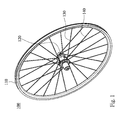
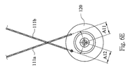
- Fig. 1 is a three dimensional view of a bicycle wheel 100 according to one embodiment of the present disclosure.
- the bicycle wheel 100 includes a rim 110, a hub 120, a plurality of pulling spokes 130, and a plurality of pushing spokes 140.
- the hub 120 is located in a center of the rim 110.
- the pulling spokes 130 of the present disclosure are defined as the spokes having a vector with a direction along an extending axis thereof from the hub 120 to the rim 110, and a direction of the moment on the center of the bicycle wheel generated from the vector is different from a rotation direction of the rim 110.
- the spokes pushing spokes 140 of the present disclosure are defined as the spokes having a vector with a direction along an extending axis thereof from the hub 120 to the rim 110, and a direction of the moment on the center of the bicycle wheel generated from the vector is the same as the rotation direction of the rim 110.
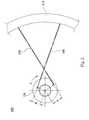
- Fig. 2 is a partially enlarged view of the bicycle wheel 100 of Fig. 1 .
- Each of the pulling spokes 130 is connected to the rim 110 and the hub 120, wherein a vertical distance between an extending axis of each of the pulling spokes 130 and a center of the hub 120 is defined as a first arm A.
- Each of the pushing spokes 140 is connected to the rim 110 and the hub 120, wherein a vertical distance between an extending axis of each of the pushing spokes 140 and the center of the hub 120 is defined as a second arm B.
- Each of the second arms B is smaller than each of the first arm A.
- C presents as a rotation direction of the rim 110.
- a number of the pulling spokes 130 can be greater than or equal to a number of the pushing spokes 140.
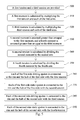
- Fig. 3 is a flowchart of a method for assembling the bicycle wheel 100 of Fig. 1 , and the method for assembling the bicycle wheel 100 includes the following steps.
- Step 200 a first tension is provided.
- Step 210 a first moment is calculated by multiplying the first tension and each of the first arms A.
- Step 220 a second moment is assumed greater than or equal to the first moment.
- Step 230 a second tension is calculated by dividing the second moment by one of the second arms B.
- each of the pulling spokes 130 is connected to the rim 110 and the hub 120 with the first tension.
- each of the pushing spokes 140 is connected to the rim 110 and the hub 120 with the second tension.
- each of the second arms B is smaller than each of the first arms A, and the second moment is smaller than the first moment for calculating the first tension and the second tension.
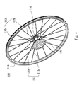
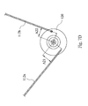
- Fig. 4 is a three dimensional view of a bicycle wheel 100 according to another embodiment of the present disclosure.
- the bicycle wheel 100 is a bicycle rear wheel, and includes a rim 110, a hub 120, a driving device 150, a plurality of first side pulling spokes 111 a, a plurality of first side pushing spokes 111 b, and a plurality of second side spokes (not labeled) including a plurality of second side pulling spokes 112a and a plurality of second side pushing spokes 112b.
- the rim 110 has a first side 111 and a second side 112.
- the hub 120 is located in a center of the rim 110.
- the driving device 150 is connected to the hub 120 which is located on the first side 111 of the rim 110.
- Each of the first side pulling spokes 111 a is connected to the rim 110 and the hub 120, and located on the first side 111 of the rim 110, wherein a vertical distance between an extending axis of each of the first side pulling spokes 111 a and the center of the hub 120 is defined as a first arm A11 (shown in Fig. 6E ).
- Each of the first side pushing spokes 111 b is connected to the rim 110 and the hub 120, and located on the first side 111 of the rim 110, wherein a vertical distance between an extending axis of each of the first side pushing spokes 111 b and the center of the hub 120 is defined as a second arm A12 (shown in Fig. 6E ).
- Each of the second side pulling spokes 112a is connected to the rim 110 and the hub 120, and located on the second side 112 of the rim 110, wherein a vertical distance between an extending axis of each of the second side pulling spokes 112a and the center of the hub 120 is defined as a third arm A21 (shown in Fig. 6D ).
- Each of the second side pushing spokes 112b is connected to the rim 110 and the hub 120, and located on the second side 112 of the rim 110, wherein a vertical distance between an extending axis of each of the second side pushing spokes 112b and the center of the hub 120 is defined as a fourth arm A22 (shown in Fig. 6D ), and each fourth arm is smaller than each third arm.
- the first side pulling spokes 111 a, the first side pushing spokes 111 b, the second side pulling spokes 112a and the second side pushing spokes 112b are connected to the hub 120 and the rim 110 in a straight-pulled method.
- the first arm A11 and the second arm A12 satisfy the following relationship: 0 ⁇ A11/A12. Therefore, durability of the bicycle wheel 100 can be increased. Moreover, the first arm A11 and the second arm A12 can satisfy the following relationship: 1 ⁇ A11/A12 ⁇ 3, 1 ⁇ A11/A12 ⁇ 1.4, 1.15 ⁇ A11/A12 ⁇ 2, 1.15 ⁇ A11/A12 ⁇ 1.4 or 1.24 ⁇ A11/A12 ⁇ 1.35.
- the third arm A21 and the fourth arm A22 satisfy the following relationship: A21/A22 ⁇ 1.
- a sum of each first arm A11 between each first side pulling spoke 111 a and the center of the hub 120 is defined as ⁇ A11
- a sum of each first arm A12 between each first side pushing spoke 111 b and the center of the hub 120 is defined as ⁇ A12, wherein ⁇ A11 - ⁇ A12 > 10 mm. Further, ⁇ A11 and ⁇ A12 can be satisfied as ⁇ A11 - ⁇ A12 > 30 mm.
- a sum of each third arm A21 between each second side pulling spoke 112a and the center of the hub 120 is defined as ⁇ A21
- a sum of each fourth arm A22 between each second side pushing spoke 112b and the center of the hub 120 is defined as ⁇ A22, wherein ( ⁇ A11 + ⁇ A21) - ( ⁇ A12 + ⁇ A22) > 10 mm.
- ⁇ A11, ⁇ A12, ⁇ A21 and ⁇ A22 can be satisfied as ( ⁇ A11 + ⁇ A21) - ( ⁇ A12 + ⁇ A22) > 30 mm.
- the first side pulling spokes can include one or more values of the first arms A11, that is, the first arms A11 of the first side pulling spokes are not limited to one value. Further, the second arms A12, the third arms A21 and the fourth arms A22 are also not limited to one value, respectively.
- Fig. 5 is a flowchart of a method for assembling the bicycle wheel 100 of Fig. 4 , and the method includes the following steps.
- Step 300 a first tension and a third tension are provided.
- Step 310 a first moment is calculated by multiplying the first tension and each of the first arms A11.
- Step 320 a third moment is calculated by multiplying the third tension and each of the third arms A21.
- Step 330 a second moment is assumed greater than or equal to the first moment, and a fourth moment is assumed greater than or equal to the third moment.
- Step 340 a second tension is calculated by dividing the second moment by the second arm A12.
- Step 350 a fourth tension is calculated by dividing the fourth moment by the fourth arm A22.
- Step 360 each of the first side pulling spokes 111 a is connected to the rim 110 and the hub 120 of the first side 111 with the first tension.
- Step 370 each of the first side pushing spokes 111 b is connected to the rim 110 and the hub 120 of the first side 111 with the second tension.
- Step 380 each of the second side pulling spokes 112a is connected to the rim 110 and the hub 120 of the second side 112 with the third tension.
- Step 390 each of the second side pushing spokes 112b is connected to the rim 110 and the hub 120 of the second side 112 with the fourth tension.
- each of the second arms A12 is smaller than each of the first arms A11
- each of the fourth arms A22 is smaller than each of the third arms A21, thus the sum of the second moment and the fourth moment is smaller than the sum of the first moment and the third moment, and the first tension, the second tension, the third tension and the fourth tension can be calculated.
- the first side pulling spokes 111 a can be connected to the rim 110 and the hub 120 of the first side 111 by the first tension
- the second side pulling spokes 112a can be connected to the rim 110 and the hub 120 of the second side 112 by the third tension
- the first side pushing spokes 111 b can be connected to the rim 110 and the hub 120 of the first side 111 by the second tension
- the second side pushing spokes 112b can be connected to the rim 110 and the hub 120 of the second side 112 by the fourth tension, so that the excessive tension between the rim 110 and the hub cab be avoided during cycling.
- the bicycle wheel and the method for assembling thereof in the present disclosure not only can avoid a problem of non-uniform tension distribution, but also can increase durability during using.
- Each of the first side pulling spokes 111 a has a first tension, and the first tension multiplied by the first arm A11 equals to a first moment, each of the first side pushing spokes 111 b has a second tension, and the second tension multiplied by the second arm A12 equals to a second moment, each of the second side pulling spokes 112a has a third t tension, and the third tension multiplied by the third arm A21 equals to a third moment, and each of the second side pushing spokes has a fourth tension, and the fourth tension multiplied by the fourth arm A22 equals to a fourth moment.
- a number of the first side pulling spokes 111 a can be greater than or equal to a number of the first side pushing spokes 111 b and a number of the second side pulling spokes 112a can be greater than a number of the second side pushing spokes 112b, or a sum of the first side pulling spokes 111 a and the first side pushing spokes 111 b can be greater than or equal to a sum of the second side pulling spokes 112a and the second side pushing spokes 112b.
- the detail number of the first side pulling spokes 111a, the first side pushing spokes 111b, the second side pulling spokes 112a, and the second side pushing spokes 112b are shown in Table 1 Table 1 Ratio of the spoke number of the first side and the spoke number of the second side First side Second side Number of total spokes Number of pulling spokes Number of pushing spokes Number of pulling spokes Number of pushing spokes Number of pushing spokes 1:1 4 2 4 2 12 4 2 2 4 12 4 2 3 3 12 5 4 5 4 18 6 3 6 3 18 6 4 5 5 20 6 5 6 5 22 7 4 7 4 22 7 5 7 5 24 7 5 6 6 24 8 4 6 6 24 8 4 6 6 24 8 4 8 4 24 7 6 7 6 26 8 5 8 5 26 8 6 8 6 28 8 6 7 7 28 8 7 8 7 30 10 5 10 5 30 9 6 9 6 30 10 6 10 6 32 10 6 8 8 32 10 7 10 7 34 12 6 9 9 36 12 6 12 6 36 2:1 6 6 3 3 18 6 6 4 2 18 8 4 3 3 18 8 4 2 18 12 6 6 3
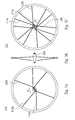
- Fig. 6A is a left-side schematic view of a bicycle wheel according to further another embodiment of the present disclosure
- Fig. 6B is a front-side schematic view of the bicycle wheel of Fig. 6A
- Fig. 6C is a right-side schematic view of the bicycle wheel of Fig. 6A .
- the right side is a first side 111 of a rim 110.
- a driving device 150 being a chain wheel is located on the first side 111.
- a number of the first side pulling spokes 111 a is 8, a number of the first side pushing spokes 111 b is 4, and a sum of the first side pulling spokes 111 a and the first side pushing spokes 111 b is 12.
- C presents a rotation direction of the rim 110.
- Fig. 6A shows a second side 112 of a rim 110 as the left side.
- a number of the second side pulling spokes 112a is 8, a number of the second side pushing spokes 112b is 4, and a sum of the second side pulling spokes 112a and the second side pushing spokes 112b is 12.
- C presents a rotation direction of the rim 110.
- a ratio of the sum of the first side pulling spokes 111 a and the first side pushing spokes 111 b and the sum the second side pulling spokes 112a and the second side pushing spokes 112b (that is, the ratio of the spoke number of the first side 111 and the spoke number of the second side 112) is 1 : 1.
- a sum of the first side pulling spokes 111a, the first side pushing spokes 111b, the second side pulling spokes 112a, and the second side pushing spokes 112b is 24.
- Fig. 6D is a partially enlarged view of the second side 112 of the bicycle wheel of Fig. 6A .
- Fig. 6E is a partially enlarged view of the first side 111 of the bicycle wheel of Fig. 6C .
- Figs. 6D is a partially enlarged view of the second side 112 of the bicycle wheel of Fig. 6A .
- Fig. 6E is a partially enlarged view of the first side 111 of the bicycle wheel of Fig. 6C .
- the vertical distance between the extending axis of each of the first side pulling spokes 111 a and the center of the hub 120 is the first arm A11
- the vertical distance between the extending axis of each of the first side pushing spokes and the center of the hub 120 is the second arm A12
- the vertical distance between the extending axis of each of the second side pulling spokes 112a and the center of the hub 120 is the third arm A21
- the vertical distance between the extending axis of each of the second side pushing spokes 112b and the center of the hub 120 is the fourth arm A22.
- the values of the first arms A11 of the first side pulling spokes 111 a are the same, that is, the first side pulling spokes 111 a include only one value of the first arms A11.
- each of the first arms A11 is 21.18 mm
- each of the second arms A12 is 21.18 mm
- each of the third arm A21 is 17.58 mm
- each of the fourth arm A22 is 17.58 mm
- ( ⁇ A11 + ⁇ A21)-( ⁇ A12 + ⁇ A22) 155.04 mm.
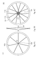
- Fig. 7A is a left-side schematic view of a bicycle wheel according to still another embodiment of the present disclosure
- Fig. 7B is a front-side schematic view of the bicycle wheel of Fig. 7A
- Fig. 7C is a right-side schematic view of the bicycle wheel of Fig. 7A .
- the right side is a first side 111 of a rim 110.
- a driving device 150 being a chain wheel is located on the first side 111.
- a number of the first side pulling spokes 111 a is 8, a number of the first side pushing spokes 111 b is 4, and a sum of the first side pulling spokes 111a and the first side pushing spokes 111b is 12.
- C presents a rotation direction of the rim 110.
- Fig. 7A shows a second side 112 of a rim 110 as the left side.
- a number of the second side pulling spokes 112a is 4, a number of the second side pushing spokes 112b is 2, and a sum of the second side pulling spokes 112a and the second side pushing spokes 112b is 6.
- C presents a rotation direction of the rim 110.
- a ratio of the sum of the first side pulling spokes 111 a and the first side pushing spokes 111 b and the sum the second side pulling spokes 112a and the second side pushing spokes 112b (that is, the ratio of the spoke number of the first side 111 and the spoke number of the second side 112) is 2 : 1.
- a sum of the first side pulling spokes 111 a, the first side pushing spokes 111b, the second side pulling spokes 112a, and the second side pushing spokes 112b is 18.
- Fig. 7D is a partially enlarged view of the second side 112 of the bicycle wheel of Fig. 7A .
- Fig. 7E is a partially enlarged view of the first side 111 of the bicycle wheel of Fig. 7C .
- Figs. 7D is a partially enlarged view of the second side 112 of the bicycle wheel of Fig. 7A .
- Fig. 7E is a partially enlarged view of the first side 111 of the bicycle wheel of Fig. 7C .
- the vertical distance between the extending axis of each of the first side pulling spokes 111 a and the center of the hub 120 is the first arm A11
- the vertical distance between the extending axis of each of the first side pushing spokes and the center of the hub 120 is the second arm A12
- the vertical distance between the extending axis of each of the second side pulling spokes 112a and the center of the hub 120 is the third arm A21
- the vertical distance between the extending axis of each of the second side pushing spokes 112b and the center of the hub 120 is the fourth arm A22.
- the first arms A11 of the first side pulling spokes 111 a include two different values, each two of the first side pulling spokes 111 a which are adjacent to each other have different values of the first arms A11.
- the third arms A21 of the second side pulling spokes 112a include two different values, each two of the second side pulling spokes 112a which are adjacent to each other have different values of the third arms A21.
- each two of the first arms A11 which are adjacent to each other are 20.13 mm, 17.58 mm, respectively
- each of the second arms A12 is 17.58 mm
- each two of the third arms A21 which are adjacent to each other are 23.11 mm, 21.98 mm, respectively
- each of the fourth arm A22 is 20.13 mm.
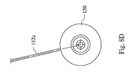
- Fig. 8A is a left-side schematic view of a bicycle wheel according to still another embodiment of the present disclosure
- Fig. 8B is a front-side schematic view of the bicycle wheel of Fig. 8A
- Fig. 8C is a right-side schematic view of the bicycle wheel of Fig. 8A .
- the bicycle wheel is a bicycle front wheel.
- the bicycle front wheel provides braking function, so that C presents a rotation direction of the rim 110 which is in the braked situation.
- the right side is a first side 111 of a rim 110.
- a driving device 150 being a chain wheel is located on the first side 111, that is, the first side 111 is a driving side.
- a number of the first side pulling spokes 111a is 7, a number of the first side pushing spokes 111 b is 7, and a sum of the first side pulling spokes 111 a and the first side pushing spokes 111 b is 14.
- a number of the second side spokes 112c is 7.
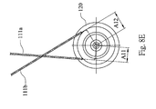
- Fig. 8D is a partially enlarged view of the second side 112 of the bicycle wheel of Fig. 8A .
- Fig. 8E is a partially enlarged view of the first side 111 of the bicycle wheel of Fig. 8C .
- the first arm A11 which represents a vertical distance between an extending axis of each of the first side pulling spokes 111 a and the center of the hub 120 is 21 mm
- the second arm A12 which represents a vertical distance between an extending axis of each of the first side pushing spokes 111 b and the center of the hub 120 is 27 mm. That is, 0 ⁇ A11/A12 ⁇ 1.
- the arm which represents a vertical distance between an extending axis of each of the second side spokes 112c and the center of the hub 120 is 0.
- the bicycle wheel and the method for assembling thereof of the present disclosure provide the following advantages.
Landscapes
- Engineering & Computer Science (AREA)
- Mechanical Engineering (AREA)
- Tires In General (AREA)
- Automatic Cycles, And Cycles In General (AREA)
- Axle Suspensions And Sidecars For Cycles (AREA)
- Motorcycle And Bicycle Frame (AREA)
Applications Claiming Priority (1)
| Application Number | Priority Date | Filing Date | Title |
|---|---|---|---|
| TW103127281A TWI610828B (zh) | 2014-08-08 | 2014-08-08 | 自行車車輪輻條結構及其製造方法 |
Publications (3)
| Publication Number | Publication Date |
|---|---|
| EP2995468A2 true EP2995468A2 (de) | 2016-03-16 |
| EP2995468A3 EP2995468A3 (de) | 2016-04-06 |
| EP2995468B1 EP2995468B1 (de) | 2019-10-02 |
Family
ID=53783585
Family Applications (1)
| Application Number | Title | Priority Date | Filing Date |
|---|---|---|---|
| EP15179901.2A Active EP2995468B1 (de) | 2014-08-08 | 2015-08-05 | Fahrradlaufrad |
Country Status (8)
| Country | Link |
|---|---|
| US (1) | US10214048B2 (de) |
| EP (1) | EP2995468B1 (de) |
| JP (1) | JP6307480B2 (de) |
| CN (1) | CN105365477B (de) |
| AU (2) | AU2015210363A1 (de) |
| CA (1) | CA2899619C (de) |
| ES (1) | ES2754299T3 (de) |
| TW (1) | TWI610828B (de) |
Families Citing this family (4)
| Publication number | Priority date | Publication date | Assignee | Title |
|---|---|---|---|---|
| CN106314035A (zh) * | 2016-09-05 | 2017-01-11 | 叶雪峰 | 车轮轮轴的中部驱动装置 |
| JP1608343S (de) * | 2017-05-24 | 2018-07-09 | ||
| CN112872752A (zh) * | 2021-01-10 | 2021-06-01 | 朱平原 | 一种摩托车辐条轮辋自动生产工艺 |
| CN113619325A (zh) * | 2021-09-02 | 2021-11-09 | 吉林大学 | 一种火星车车轮 |
Family Cites Families (14)
| Publication number | Priority date | Publication date | Assignee | Title |
|---|---|---|---|---|
| US2702725A (en) * | 1950-07-15 | 1955-02-22 | D P Harris Hardware & Mfg Co I | Spoke wheel and hub therefor |
| US3907372A (en) * | 1974-08-08 | 1975-09-23 | Leonard Goldberg | Spoked wheel |
| US5246275A (en) | 1987-08-21 | 1993-09-21 | Arredondo Jr Rene N | Wheel for bicycles and method of producing |
| US5494337A (en) * | 1993-08-13 | 1996-02-27 | Behnke; James W. | Bicycle wheel with a straight through spoke and hub combination |
| JP3069284B2 (ja) * | 1996-01-26 | 2000-07-24 | 株式会社シマノ | 自転車用ハブ |
| US6145938A (en) * | 1996-10-11 | 2000-11-14 | Dietrich; Rolf | Cycle, tensioned spoked wheel assembly and hub therefor |
| US6024414A (en) * | 1997-08-25 | 2000-02-15 | Dietrich; Rolf | Tensioned spoked bicycle wheel assembly and hub therefor |
| IT245313Y1 (it) * | 1998-06-05 | 2002-03-20 | Aprilia World Service B V | Ruota a raggi perfezionata |
| US6283557B1 (en) * | 2000-03-16 | 2001-09-04 | Shimano, Inc. | Bicycle rim with wear indicator |
| DE50103307D1 (de) * | 2000-12-19 | 2004-09-23 | Jiri Krampera | Gespeichtes Fahrrad-Rad |
| ITTO20010806A1 (it) * | 2001-08-09 | 2003-02-09 | Campagnolo Srl | Ruota a raggi per bicicletta e procedimento per la sua fabbricazione. |
| DE602005015425D1 (de) * | 2005-05-02 | 2009-08-27 | Campagnolo Srl | Radnabe für ein Fahrrad-Speichenrad |
| FR2890896B1 (fr) * | 2005-09-16 | 2007-10-26 | Salomon Sa | Procede de fabrication d'une roue a rayons en tension et roue a rayons en tension |
| TW201008796A (en) * | 2008-08-22 | 2010-03-01 | Shimano Kk | Spoke wheel of bicycle rear wheel |
-
2014
- 2014-08-08 TW TW103127281A patent/TWI610828B/zh active
-
2015
- 2015-08-04 CA CA2899619A patent/CA2899619C/en active Active
- 2015-08-05 ES ES15179901T patent/ES2754299T3/es active Active
- 2015-08-05 AU AU2015210363A patent/AU2015210363A1/en not_active Abandoned
- 2015-08-05 EP EP15179901.2A patent/EP2995468B1/de active Active
- 2015-08-06 JP JP2015155842A patent/JP6307480B2/ja active Active
- 2015-08-06 US US14/819,442 patent/US10214048B2/en active Active
- 2015-08-07 CN CN201510480930.6A patent/CN105365477B/zh active Active
-
2017
- 2017-10-26 AU AU2017251794A patent/AU2017251794B2/en active Active
Non-Patent Citations (1)
| Title |
|---|
| None |
Also Published As
| Publication number | Publication date |
|---|---|
| TWI610828B (zh) | 2018-01-11 |
| EP2995468B1 (de) | 2019-10-02 |
| ES2754299T3 (es) | 2020-04-16 |
| JP6307480B2 (ja) | 2018-04-04 |
| AU2017251794B2 (en) | 2019-10-03 |
| CN105365477B (zh) | 2019-01-25 |
| CA2899619A1 (en) | 2016-02-08 |
| JP2016037285A (ja) | 2016-03-22 |
| CN105365477A (zh) | 2016-03-02 |
| TW201605658A (zh) | 2016-02-16 |
| AU2017251794A1 (en) | 2017-11-16 |
| CA2899619C (en) | 2018-06-05 |
| US20160039245A1 (en) | 2016-02-11 |
| AU2015210363A1 (en) | 2016-02-25 |
| US10214048B2 (en) | 2019-02-26 |
| EP2995468A3 (de) | 2016-04-06 |
Similar Documents
| Publication | Publication Date | Title |
|---|---|---|
| EP2995468A2 (de) | Fahrradlaufrad | |
| US9926038B2 (en) | Bicycle sprocket, bicycle rear sprocket, and bicycle multiple sprocket assembly | |
| US20090243250A1 (en) | Bicycle sprocket assembly | |
| US20140265539A1 (en) | Bicycle with improved chain line | |
| US20080136248A1 (en) | Spoked wheel for a bicycle | |
| US20090250995A1 (en) | Composite Carbon Fiber Wheel Rim and Method of Making Thereof | |
| WO2005108120A3 (en) | Bicycle wheel | |
| US10113632B2 (en) | Bicycle sprocket wheel unit and mounting unit for cooperating with sprocket wheels | |
| US20120146393A1 (en) | Wheel rim with a brake rotor | |
| JP2002274103A (ja) | 車両用アルミホイール | |
| US20180162157A1 (en) | Bicycle wheel and method of manufacturing bicycle wheel | |
| US7029074B2 (en) | Wheel rim with anchor members connected to spokes | |
| US8480182B2 (en) | Rear hub assembly for bicycle | |
| US20070085413A1 (en) | Spoke assembling structure for a bicycle wheel | |
| CN107458145A (zh) | 一种耐用型多辐条汽车轮毂 | |
| CN101659178B (zh) | 自行车用后轮辐条轮圈 | |
| CN204937203U (zh) | 方向盘 | |
| CN102248856B (zh) | 自行车用后轮辐条轮圈 | |
| EP1557292A1 (de) | Felgenrad für Fahrräder mit Bohrungen in den Felgenflanken zum Einführen der Speichennippel | |
| JP6368731B2 (ja) | 車両用ホイール | |
| CN206690800U (zh) | 一种轮圈、单臂轮组总成及自行车 | |
| US20140062167A1 (en) | Wheel rim structure | |
| US20170144477A1 (en) | Wheel Hub and Wheel Including the Same | |
| EP2156964A3 (de) | Speichenhinterrad für ein Fahrrad | |
| CN206703836U (zh) | 一种抗开裂的车轮 |
Legal Events
| Date | Code | Title | Description |
|---|---|---|---|
| PUAL | Search report despatched |
Free format text: ORIGINAL CODE: 0009013 |
|
| PUAI | Public reference made under article 153(3) epc to a published international application that has entered the european phase |
Free format text: ORIGINAL CODE: 0009012 |
|
| 17P | Request for examination filed |
Effective date: 20151123 |
|
| AK | Designated contracting states |
Kind code of ref document: A2 Designated state(s): AL AT BE BG CH CY CZ DE DK EE ES FI FR GB GR HR HU IE IS IT LI LT LU LV MC MK MT NL NO PL PT RO RS SE SI SK SM TR |
|
| AX | Request for extension of the european patent |
Extension state: BA ME |
|
| AK | Designated contracting states |
Kind code of ref document: A3 Designated state(s): AL AT BE BG CH CY CZ DE DK EE ES FI FR GB GR HR HU IE IS IT LI LT LU LV MC MK MT NL NO PL PT RO RS SE SI SK SM TR |
|
| AX | Request for extension of the european patent |
Extension state: BA ME |
|
| RIC1 | Information provided on ipc code assigned before grant |
Ipc: B60B 1/02 20060101ALI20160226BHEP Ipc: B60B 1/04 20060101ALI20160226BHEP Ipc: B60B 27/00 20060101ALI20160226BHEP Ipc: B60B 27/02 20060101ALI20160226BHEP Ipc: B60B 1/00 20060101AFI20160226BHEP |
|
| STAA | Information on the status of an ep patent application or granted ep patent |
Free format text: STATUS: EXAMINATION IS IN PROGRESS |
|
| 17Q | First examination report despatched |
Effective date: 20180411 |
|
| GRAP | Despatch of communication of intention to grant a patent |
Free format text: ORIGINAL CODE: EPIDOSNIGR1 |
|
| STAA | Information on the status of an ep patent application or granted ep patent |
Free format text: STATUS: GRANT OF PATENT IS INTENDED |
|
| INTG | Intention to grant announced |
Effective date: 20190404 |
|
| GRAS | Grant fee paid |
Free format text: ORIGINAL CODE: EPIDOSNIGR3 |
|
| GRAA | (expected) grant |
Free format text: ORIGINAL CODE: 0009210 |
|
| STAA | Information on the status of an ep patent application or granted ep patent |
Free format text: STATUS: THE PATENT HAS BEEN GRANTED |
|
| AK | Designated contracting states |
Kind code of ref document: B1 Designated state(s): AL AT BE BG CH CY CZ DE DK EE ES FI FR GB GR HR HU IE IS IT LI LT LU LV MC MK MT NL NO PL PT RO RS SE SI SK SM TR |
|
| REG | Reference to a national code |
Ref country code: GB Ref legal event code: FG4D |
|
| REG | Reference to a national code |
Ref country code: AT Ref legal event code: REF Ref document number: 1185763 Country of ref document: AT Kind code of ref document: T Effective date: 20191015 Ref country code: CH Ref legal event code: EP |
|
| REG | Reference to a national code |
Ref country code: DE Ref legal event code: R096 Ref document number: 602015038954 Country of ref document: DE |
|
| REG | Reference to a national code |
Ref country code: IE Ref legal event code: FG4D |
|
| REG | Reference to a national code |
Ref country code: NL Ref legal event code: FP |
|
| REG | Reference to a national code |
Ref country code: LT Ref legal event code: MG4D |
|
| REG | Reference to a national code |
Ref country code: CH Ref legal event code: NV Representative=s name: LANGPATENT ANWALTSKANZLEI IP LAW FIRM, CH |
|
| REG | Reference to a national code |
Ref country code: AT Ref legal event code: MK05 Ref document number: 1185763 Country of ref document: AT Kind code of ref document: T Effective date: 20191002 |
|
| REG | Reference to a national code |
Ref country code: ES Ref legal event code: FG2A Ref document number: 2754299 Country of ref document: ES Kind code of ref document: T3 Effective date: 20200416 |
|
| PG25 | Lapsed in a contracting state [announced via postgrant information from national office to epo] |
Ref country code: BG Free format text: LAPSE BECAUSE OF FAILURE TO SUBMIT A TRANSLATION OF THE DESCRIPTION OR TO PAY THE FEE WITHIN THE PRESCRIBED TIME-LIMIT Effective date: 20200102 Ref country code: FI Free format text: LAPSE BECAUSE OF FAILURE TO SUBMIT A TRANSLATION OF THE DESCRIPTION OR TO PAY THE FEE WITHIN THE PRESCRIBED TIME-LIMIT Effective date: 20191002 Ref country code: SE Free format text: LAPSE BECAUSE OF FAILURE TO SUBMIT A TRANSLATION OF THE DESCRIPTION OR TO PAY THE FEE WITHIN THE PRESCRIBED TIME-LIMIT Effective date: 20191002 Ref country code: PT Free format text: LAPSE BECAUSE OF FAILURE TO SUBMIT A TRANSLATION OF THE DESCRIPTION OR TO PAY THE FEE WITHIN THE PRESCRIBED TIME-LIMIT Effective date: 20200203 Ref country code: LV Free format text: LAPSE BECAUSE OF FAILURE TO SUBMIT A TRANSLATION OF THE DESCRIPTION OR TO PAY THE FEE WITHIN THE PRESCRIBED TIME-LIMIT Effective date: 20191002 Ref country code: GR Free format text: LAPSE BECAUSE OF FAILURE TO SUBMIT A TRANSLATION OF THE DESCRIPTION OR TO PAY THE FEE WITHIN THE PRESCRIBED TIME-LIMIT Effective date: 20200103 Ref country code: PL Free format text: LAPSE BECAUSE OF FAILURE TO SUBMIT A TRANSLATION OF THE DESCRIPTION OR TO PAY THE FEE WITHIN THE PRESCRIBED TIME-LIMIT Effective date: 20191002 Ref country code: AT Free format text: LAPSE BECAUSE OF FAILURE TO SUBMIT A TRANSLATION OF THE DESCRIPTION OR TO PAY THE FEE WITHIN THE PRESCRIBED TIME-LIMIT Effective date: 20191002 Ref country code: LT Free format text: LAPSE BECAUSE OF FAILURE TO SUBMIT A TRANSLATION OF THE DESCRIPTION OR TO PAY THE FEE WITHIN THE PRESCRIBED TIME-LIMIT Effective date: 20191002 Ref country code: NO Free format text: LAPSE BECAUSE OF FAILURE TO SUBMIT A TRANSLATION OF THE DESCRIPTION OR TO PAY THE FEE WITHIN THE PRESCRIBED TIME-LIMIT Effective date: 20200102 |
|
| PG25 | Lapsed in a contracting state [announced via postgrant information from national office to epo] |
Ref country code: CZ Free format text: LAPSE BECAUSE OF FAILURE TO SUBMIT A TRANSLATION OF THE DESCRIPTION OR TO PAY THE FEE WITHIN THE PRESCRIBED TIME-LIMIT Effective date: 20191002 Ref country code: HR Free format text: LAPSE BECAUSE OF FAILURE TO SUBMIT A TRANSLATION OF THE DESCRIPTION OR TO PAY THE FEE WITHIN THE PRESCRIBED TIME-LIMIT Effective date: 20191002 Ref country code: IS Free format text: LAPSE BECAUSE OF FAILURE TO SUBMIT A TRANSLATION OF THE DESCRIPTION OR TO PAY THE FEE WITHIN THE PRESCRIBED TIME-LIMIT Effective date: 20200224 Ref country code: RS Free format text: LAPSE BECAUSE OF FAILURE TO SUBMIT A TRANSLATION OF THE DESCRIPTION OR TO PAY THE FEE WITHIN THE PRESCRIBED TIME-LIMIT Effective date: 20191002 |
|
| PG25 | Lapsed in a contracting state [announced via postgrant information from national office to epo] |
Ref country code: AL Free format text: LAPSE BECAUSE OF FAILURE TO SUBMIT A TRANSLATION OF THE DESCRIPTION OR TO PAY THE FEE WITHIN THE PRESCRIBED TIME-LIMIT Effective date: 20191002 |
|
| REG | Reference to a national code |
Ref country code: DE Ref legal event code: R097 Ref document number: 602015038954 Country of ref document: DE |
|
| PG2D | Information on lapse in contracting state deleted |
Ref country code: IS |
|
| PG25 | Lapsed in a contracting state [announced via postgrant information from national office to epo] |
Ref country code: IS Free format text: LAPSE BECAUSE OF FAILURE TO SUBMIT A TRANSLATION OF THE DESCRIPTION OR TO PAY THE FEE WITHIN THE PRESCRIBED TIME-LIMIT Effective date: 20200202 Ref country code: EE Free format text: LAPSE BECAUSE OF FAILURE TO SUBMIT A TRANSLATION OF THE DESCRIPTION OR TO PAY THE FEE WITHIN THE PRESCRIBED TIME-LIMIT Effective date: 20191002 Ref country code: RO Free format text: LAPSE BECAUSE OF FAILURE TO SUBMIT A TRANSLATION OF THE DESCRIPTION OR TO PAY THE FEE WITHIN THE PRESCRIBED TIME-LIMIT Effective date: 20191002 Ref country code: DK Free format text: LAPSE BECAUSE OF FAILURE TO SUBMIT A TRANSLATION OF THE DESCRIPTION OR TO PAY THE FEE WITHIN THE PRESCRIBED TIME-LIMIT Effective date: 20191002 |
|
| PLBE | No opposition filed within time limit |
Free format text: ORIGINAL CODE: 0009261 |
|
| STAA | Information on the status of an ep patent application or granted ep patent |
Free format text: STATUS: NO OPPOSITION FILED WITHIN TIME LIMIT |
|
| PG25 | Lapsed in a contracting state [announced via postgrant information from national office to epo] |
Ref country code: SK Free format text: LAPSE BECAUSE OF FAILURE TO SUBMIT A TRANSLATION OF THE DESCRIPTION OR TO PAY THE FEE WITHIN THE PRESCRIBED TIME-LIMIT Effective date: 20191002 Ref country code: SM Free format text: LAPSE BECAUSE OF FAILURE TO SUBMIT A TRANSLATION OF THE DESCRIPTION OR TO PAY THE FEE WITHIN THE PRESCRIBED TIME-LIMIT Effective date: 20191002 |
|
| 26N | No opposition filed |
Effective date: 20200703 |
|
| PG25 | Lapsed in a contracting state [announced via postgrant information from national office to epo] |
Ref country code: SI Free format text: LAPSE BECAUSE OF FAILURE TO SUBMIT A TRANSLATION OF THE DESCRIPTION OR TO PAY THE FEE WITHIN THE PRESCRIBED TIME-LIMIT Effective date: 20191002 |
|
| PG25 | Lapsed in a contracting state [announced via postgrant information from national office to epo] |
Ref country code: MC Free format text: LAPSE BECAUSE OF FAILURE TO SUBMIT A TRANSLATION OF THE DESCRIPTION OR TO PAY THE FEE WITHIN THE PRESCRIBED TIME-LIMIT Effective date: 20191002 |
|
| PG25 | Lapsed in a contracting state [announced via postgrant information from national office to epo] |
Ref country code: LU Free format text: LAPSE BECAUSE OF NON-PAYMENT OF DUE FEES Effective date: 20200805 |
|
| REG | Reference to a national code |
Ref country code: BE Ref legal event code: MM Effective date: 20200831 |
|
| PG25 | Lapsed in a contracting state [announced via postgrant information from national office to epo] |
Ref country code: IE Free format text: LAPSE BECAUSE OF NON-PAYMENT OF DUE FEES Effective date: 20200805 Ref country code: BE Free format text: LAPSE BECAUSE OF NON-PAYMENT OF DUE FEES Effective date: 20200831 |
|
| PG25 | Lapsed in a contracting state [announced via postgrant information from national office to epo] |
Ref country code: TR Free format text: LAPSE BECAUSE OF FAILURE TO SUBMIT A TRANSLATION OF THE DESCRIPTION OR TO PAY THE FEE WITHIN THE PRESCRIBED TIME-LIMIT Effective date: 20191002 Ref country code: MT Free format text: LAPSE BECAUSE OF FAILURE TO SUBMIT A TRANSLATION OF THE DESCRIPTION OR TO PAY THE FEE WITHIN THE PRESCRIBED TIME-LIMIT Effective date: 20191002 Ref country code: CY Free format text: LAPSE BECAUSE OF FAILURE TO SUBMIT A TRANSLATION OF THE DESCRIPTION OR TO PAY THE FEE WITHIN THE PRESCRIBED TIME-LIMIT Effective date: 20191002 |
|
| PG25 | Lapsed in a contracting state [announced via postgrant information from national office to epo] |
Ref country code: MK Free format text: LAPSE BECAUSE OF FAILURE TO SUBMIT A TRANSLATION OF THE DESCRIPTION OR TO PAY THE FEE WITHIN THE PRESCRIBED TIME-LIMIT Effective date: 20191002 |
|
| PGFP | Annual fee paid to national office [announced via postgrant information from national office to epo] |
Ref country code: NL Payment date: 20250706 Year of fee payment: 11 |
|
| PGFP | Annual fee paid to national office [announced via postgrant information from national office to epo] |
Ref country code: ES Payment date: 20250901 Year of fee payment: 11 |
|
| PGFP | Annual fee paid to national office [announced via postgrant information from national office to epo] |
Ref country code: DE Payment date: 20250715 Year of fee payment: 11 |
|
| PGFP | Annual fee paid to national office [announced via postgrant information from national office to epo] |
Ref country code: IT Payment date: 20250722 Year of fee payment: 11 |
|
| PGFP | Annual fee paid to national office [announced via postgrant information from national office to epo] |
Ref country code: GB Payment date: 20250710 Year of fee payment: 11 |
|
| PGFP | Annual fee paid to national office [announced via postgrant information from national office to epo] |
Ref country code: FR Payment date: 20250714 Year of fee payment: 11 |
|
| PGFP | Annual fee paid to national office [announced via postgrant information from national office to epo] |
Ref country code: CH Payment date: 20250901 Year of fee payment: 11 |