EP2995427A1 - Elektrowerkzeug - Google Patents
Elektrowerkzeug Download PDFInfo
- Publication number
- EP2995427A1 EP2995427A1 EP15154780.9A EP15154780A EP2995427A1 EP 2995427 A1 EP2995427 A1 EP 2995427A1 EP 15154780 A EP15154780 A EP 15154780A EP 2995427 A1 EP2995427 A1 EP 2995427A1
- Authority
- EP
- European Patent Office
- Prior art keywords
- phases
- brushless motor
- electric tool
- crossover
- crossover wires
- Prior art date
- Legal status (The legal status is an assumption and is not a legal conclusion. Google has not performed a legal analysis and makes no representation as to the accuracy of the status listed.)
- Granted
Links
Images








Classifications
-
- B—PERFORMING OPERATIONS; TRANSPORTING
- B25—HAND TOOLS; PORTABLE POWER-DRIVEN TOOLS; MANIPULATORS
- B25F—COMBINATION OR MULTI-PURPOSE TOOLS NOT OTHERWISE PROVIDED FOR; DETAILS OR COMPONENTS OF PORTABLE POWER-DRIVEN TOOLS NOT PARTICULARLY RELATED TO THE OPERATIONS PERFORMED AND NOT OTHERWISE PROVIDED FOR
- B25F5/00—Details or components of portable power-driven tools not particularly related to the operations performed and not otherwise provided for
-
- H—ELECTRICITY
- H02—GENERATION; CONVERSION OR DISTRIBUTION OF ELECTRIC POWER
- H02K—DYNAMO-ELECTRIC MACHINES
- H02K3/00—Details of windings
- H02K3/04—Windings characterised by the conductor shape, form or construction, e.g. with bar conductors
- H02K3/28—Layout of windings or of connections between windings
-
- H—ELECTRICITY
- H02—GENERATION; CONVERSION OR DISTRIBUTION OF ELECTRIC POWER
- H02K—DYNAMO-ELECTRIC MACHINES
- H02K7/00—Arrangements for handling mechanical energy structurally associated with dynamo-electric machines, e.g. structural association with mechanical driving motors or auxiliary dynamo-electric machines
- H02K7/14—Structural association with mechanical loads, e.g. with hand-held machine tools or fans
- H02K7/145—Hand-held machine tool
Definitions
- the present invention relates to an electric tool configured to use a brushless motor as a driving source.
- a brushless motor has been adopted in an electric tool configured to rotate a tip tool such as a drill and a driver by a motor, thereby performing a predetermined operation.
- the brushless motor has, in general, Y connected (star connected) or ⁇ -connected three-phase windings.
- the three-phase windings are energized by an inverter.
- the inverter has switching elements connected to a plus-side and a minus-side of each phase winding (stator coil), i.e., a total of six switching elements, and is configured to sequentially energize the predetermined stator coils. By a magnetic field generated by the stator coils, a rotor having a magnet is rotated.
- the respective switching elements configuring the inverter are arranged on a switching substrate in the vicinity of the brushless motor.
- the brushless motor is a three-phase motor and the stator has six poles, for example, two stator coils are provided for each phase.
- the stator coils of each phase are connected in series, a resistance (copper loss) of the stator coils with respect to a power supply voltage is large, which is unfavorable for a high output.
- a line diameter of the stator coil is increased, it is possible to reduce the resistance.
- a width of a winding slot is limited, so that there is a limitation on the increase in the line diameter.
- An aspect of the present disclosure provides the following arrangements:
- An electric tool comprising:
- any combination of the above-described constitutional elements and a conversion of the expression of the present invention into a method, a system and the like are also effective as aspects of the present invention.
- the electric motor having the brushless motor capable of increasing an output, as compared to the related art.
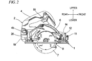
- FIGS. 1 to 4 are a plan view, a side view, a rear view, and a front view showing a cordless circular saw according to an embodiment of the present invention, respectively.
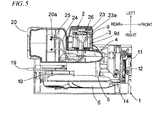
- FIG. 5 is a first plan view of the cordless circular saw where a portion thereof is shown as a cross-section.
- FIG. 6 is a second plan view of the cordless circular saw where another portion thereof is shown as a cross-section.
- FIG. 7 is a cross-sectional view taken along a line A-A of FIG. 1 .
- the cordless circular saw of the present embodiment includes a base 1 and a main body 2.
- the base 1 is a plate material made of a metal such as aluminum substantially in a rectangular shape.
- the longitudinal direction of the base 1 coincides with a cutting direction.
- the bottom of the base member 101 is a surface to slide on a workpiece.
- the main body 2 is joined with the base 1 at two positions in a front-rear direction such that the main body can rotate and tilt leftward or rightward with respect to the base 1.
- the main body 2 includes a motor housing 3, a handle portion 4, a gear cover 5, a saw cover 6, a protective cover 7, and a circular saw blade 8.
- the motor housing 3 is made of, for example, a resin, and accommodates a brushless motor 9 ( FIGS. 5 and 6 ).
- the brushless motor 9 rotates the circular saw blade 8.
- the handle portion 4 is made of the same material as that of the motor housing 3 and is integrally formed with the motor housing 3, and extends in the front-rear direction on the motor housing 3.
- the handle portion 4 includes a switch 18 for allowing a user to control the driving of the brushless-motor.
- the handle portion 4 is configured by a left component provided integrally with the motor housing 3, and a right component interposed between the motor housing 3 and the gear cover 5, and the left component and the right component are combined to configure a battery pack attaching portion 4a (to be described below), and a control circuit board accommodating portion 4b (to be described below) is provided at the right component of the handle portion 4 positioned on a side of the circular saw blade 8.
- the boundary between the left component and the right component of the handle portion 4 is a line shown at the center of the handle portion 4 in FIG. 1 , FIG. 3, FIG. 4 , and so on.
- the battery pack attaching portion 4a (a battery attaching portion) and the control circuit board accommodating portion 4b are integrally provided.
- a battery pack 20 (a rechargeable battery) is slid into the battery pack attaching portion 4a from the rear side, thereby being removably attached.
- a tact switch 16 is disposed on an upper surface of the battery pack attaching portion 4a.
- the battery pack 20 supplies driving power to the brushless motor 9. As shown in FIG. 1 , the left surface of the battery pack 20 attached to the battery pack attaching portion 4a, and the left surface of the motor housing 3 exist substantially on the same plane.
- the control circuit board accommodating portion 4b is provided on the right side of the battery pack 20. In the control circuit board accommodating portion 4b, a control circuit board 21 is stored and held.
- the control circuit board 21 has a control unit (a controller) mounted thereon for controlling the operation of the brushless motor 9.
- the control circuit board 21 is substantially perpendicular to the rotation axis of the brushless motor 9 (the rotation axis of the circular saw blade 8).
- the control circuit board 21, more specifically, the left side of the control circuit board 21 is partitioned off from the battery pack 20 by a controller cover 22 made of, for example, a resin.
- the gear cover 5 is provided on the right side of the handle portion 4.
- the gear cover 5 is made of, for example, a metal, and accommodates a mechanism for transmitting rotation between the brushless motor 9 and the circular saw blade 8.
- the rotation transmitting mechanism is configured by a known deceleration mechanism.
- the saw cover 6 is attached to the gear cover 5, and covers the upper half of the circular saw blade 8 in conjunction with the gear cover 5.
- the saw cover 6 may be formed of the same material as that of the gear cover 5, integrally with the gear cover 5.
- the front end portions of the gear cover 5 and the saw cover 6 are rotatably joined by a rotation supporting unit 14.
- the protective cover 7 is made of, for example, a resin, and is rotatably provided along the outer edges of the gear cover 5 and the saw cover 6 on the rear side of the gear cover 5. Between the gear cover 5 and the protective cover 7, a spring (not shown) is interposed. This spring biases the protective cover 7 against the gear cover 5, in a direction (a counterclockwise direction in FIG. 2 ) for covering the lower half of the circular saw blade 8 in the circumferential direction of the gear cover 5 and the saw cover 6. Therefore, in a state where cutting work is not being performed, the protective cover 7 covers the lower half of the circular saw blade 8 (a portion protruding from the bottom of the base 1), except for a portion of the front side.
- a bevel plate 12 is provided to stand.
- the bevel plate 12 stands in a short-length direction substantially perpendicular to a cutting direction.
- the bevel plate 12 has a long hole 13.
- the long hole 13 has an arc shape having a first tilt shaft portion 15a extending in the cutting direction, as the center, and perpendicular to the first tilt shaft portion 15a.
- the rotation supporting unit 14 is supported to be able to tilt on the first tilt shaft portion 15a to left or right with respect to the base 1.
- the tilt position of the rotation supporting unit 14 is adjusted in a state where a tilt-angle adjusting lever 11 is loose, and is fixed by fastening the tilt-angle adjusting lever 11.
- the rotation supporting unit 14 rotatably supports the front end portion of the saw cover 6 on an axis parallel to the rotation axis of the brushless motor 9 (the rotation axis of the circular saw blade 8). Adjusting and fixing of the rotational position of the saw cover 6 will be described below.
- a link 10 is provided along the left surface of the gear cover 5 so as to be rotatable around a tilt shaft portion 15b concentric with the first tilt shaft portion 15a.
- the link 10 is made of a metal such as aluminum.
- the brushless motor 9 has a rotor core 9b around an output shaft 9a.
- the output shaft 9a is parallel to the rotation axis of the circular saw blade 8.
- the rotor core 9b rotates integrally with the output shaft 9a.
- a rotor magnet 9c is inserted into and supported in the rotor core 9b.
- a stator core 9d is provided to surround the outer circumferential surface of the rotor core 9b.
- a stator coil 9f is provided with a pair of insulators 9e interposed therebetween.
- a switching board 23 is fixed. The switching board 23 is substantially perpendicular to the output shaft 9a.
- switching devices 23a (such as FETs) are mounted such that their main body portions are laid down.
- the switching devices 23a switch a supply voltage from the battery pack 20.
- a terminal portion 20a of the battery pack 20, and the switching board 23 are electrically connected to each other by a wiring line 24.
- a wiring line 25 electrically connects the terminal portion 20a of the battery pack 20 and the control circuit board 21 to each other.
- a wiring line 26 electrically connects the control circuit board 21 and the switching board 23 to each other.
- a control signal from the controller of the control circuit board 21 is applied to control terminals (gates) of the switching devices 23a mounted on the switching board 23, by the wiring line 26, whereby ON/OFF of the switching devices 23a is controlled.
- a cooling fan 33 is attached to the output shaft 9a of the brushless motor 9, and rotates with the output shaft 9a. The cooling fan 33 generates an air flow which cools the brushless motor 9 and the switching devices 23a.
- Fig. 8 is a front view of the stator of the brushless motor 9 shown in Figs. 5 and 6
- Fig. 9 is a right side view of Fig. 8
- Fig. 10 is a rear view of Fig. 8
- Fig. 11 is an enlarged view of main parts of Fig. 9
- Fig. 12 is an enlarged view of main parts of Fig. 10
- Fig. 13 is a pictorial view of windings of stator coils 9f of each phase of the brushless motor 9 (which corresponds to a state showing the developed stator core 9d as seen from an outer periphery-side).
- Fig. 14 illustrates a wire connection of Fig. 13 .
- the brushless motor 9 has three phases, and stator coils 9f (U1, U2, V1, V2, W1, W2 in Fig. 14 ) of a U phase, a V phase and a W phase are Y-connected.
- the two stator coils 9f are provided in parallel for each phase.
- the stator coils 9f of the respective phases are connected each other at a neutral point 9h.
- the two stator coils 9f of each phase are the same as regards a winding direction as seen from an outer periphery and are electrically connected to each other by a crossover wire 9i.
- the crossover wires 9i of all phases are electrically connected to each other at one place, thereby configuring the neutral point 9h.
- the insulator 9e is provided on an opposite end surface of the stator core 9d to the switching substrate 23, and the crossover wires 9i of the respective phases extend around the output shaft (rotary shaft) 9a of the brushless motor 9 on an opposite surface of the insulator 9e to the stator core 9d and are electrically connected to each other on the surface of the insulator 9e.
- a plurality of guide ribs 9t is provided along the periphery of the output shaft 9a of the brushless motor 9 and is configured to guide the crossover wires 9i of the respective phases.
- the three crossover wires 9i are arranged so that portions thereof overlap in a direction parallel with the output shaft 9a of the brushless motor 9 ( Fig. 11 ), and are bound by winding a conductive wire material 9j (for example, tin plated wire and the like) several times at the overlapping portions, and the bound portions are fixed by a soldering.
- a conductive wire material 9j for example, tin plated wire and the like
- the wire material configuring the stator coil 9f is an insulating sheathed wire.
- the respective crossover wires 9i have insulating sheath-removed portions 9m at the portions (the portions contacting the conductive wire material 9j and a soldering 9n) bound by the conductive wire material 9j, so that they can be conducted each other.
- a surface of the soldering 9n is covered by an insulating material 9p.
- the insulator 9e has a pair of convex parts 9k.
- the pair of convex parts 9k is configured to raise both sides of the portions of the crossover wires 9i bound by the conductive wire material 9j.
- a gap 9s ( Fig. 11 ) is formed between the crossover wires 9i and the insulator 9e, so that the operability is improved when binding the crossover wires 9i by the conductive wire material 9j.
- opposite end portions of the respective stator coils 9f to the crossover wires 9i are drawn out on the switching substrate 23 by lead wire parts 9r and are electrically connected to a conductive pattern on the switching substrate 23.
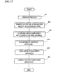
- Fig. 15 is a flowchart showing a manufacturing process of the brushless motor 9.
- the insulating sheathed wires are wound in the respective winding slots of the stator core 9d, so that the stator coils 9f of the respective phases are formed (S1).
- the insulating sheath of a portion of the crossover wire 9i of each phase, which is electrically connected to the crossover wires 9i of the other phases, is removed (S2).
- the three crossover wires 9i are bound and coupled by the conductive wire material 9j (S3), the coupled portions are further fixed by the soldering (S4) and a surface of the soldering is insulating-sheathed (S5).
- the lead wire parts 9r of the respective stator coils 9f are electrically connected to the conductive pattern on the switching substrate 23 (S6).
- the connection of the lead wire parts 9r to the switching substrate 23 may be performed between steps S1 and S2 of Fig. 15 .
- Fig. 18 is a front view of a stator of a brushless motor of a cordless round saw according to a second illustrative embodiment of the present invention.
- the lead wire part 9r of the stator coil 9f of the U1 phase is drawn out to the outer periphery-side through a recess portion 9u, as it is, and the lead wire part 9r of the stator coil 9f of the U2 phase is extended with being insulating-sheathed towards the U1 phase and is then drawn out to the outer periphery-side through the recess portion 9u together with the lead wire part 9r of the stator coil 9f of the U1 phase.
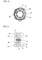
- Fig. 19 is a pictorial view of windings of the stator coils 9f of each phase of a brushless motor of a cordless round saw according to a third illustrative embodiment of the present invention.
- Fig. 20 is a rear view of a stator of the brushless motor.
- the crossover wire 9i of the U phase and the crossover wire 9i of the W phase are electrically connected to each other at one place, and the crossover wire 9i of the V phase and the crossover wire 9i of the W phase are electrically connected to each other at one separate place.
- connection places of the crossover wires 9i are increased to increase the number of processes, it is possible to reduce the number of the crossover wires 9i overlapping in the direction parallel with the output shaft 9a of the brushless motor 9 by two, which is advantageous when it is intended to shorten an axial size of the brushless motor 9.
- the others of the third illustrative embodiment are the same as the first illustrative embodiment, and the same effects can be accomplished.
- Fig. 21 illustrates a wire connection of the stator coils 9f of the respective phase of a brushless motor of a cordless round saw according to a fourth illustrative embodiment of the present invention.
- Fig. 22 is an enlarged view of a wire connected part of the stator coils 9f of the fourth illustrative embodiment.
- the stator coils 9f U1, U2, V1, V2, W1, W2 in Fig. 21
- the lead wire parts 9r of the two stator coils 9f of any phase and the crossover wires 9i of the stator coils 9f of the other phases are encircled around the rotary shaft of the brushless motor on the plane of the insulator, as shown in Fig. 22 , like the first illustrative embodiment, and are electrically connected to each other together with a lead wire 9x connected to the switching substrate 23.
- the connection can be performed by both the binding using the conductive wire material 9j and the soldering, like the first illustrative embodiment.
- the wire connected part shown in Fig. 22 is provided at three places. The others of the third illustrative embodiment are the same as the first illustrative embodiment, and the same effects can be accomplished.
- the stator coils 9f of each phase may be three or more.
- the fixing of the wire connected part may be made by the binding using the conductive wire material 9j or the soldering, or may be made by the other electrical connection methods.
- the electric tool to which the present invention is applied is not limited to the cordless round saw and may be an electric tool (a drill driver and the like) having a tip tool such as a drill and a driver attached thereto, an electric tool (a dust collector or air compressor) having no tip tool, and the like.
Landscapes
- Engineering & Computer Science (AREA)
- Power Engineering (AREA)
- Mechanical Engineering (AREA)
- Insulation, Fastening Of Motor, Generator Windings (AREA)
- Portable Power Tools In General (AREA)
- Brushless Motors (AREA)
Applications Claiming Priority (1)
| Application Number | Priority Date | Filing Date | Title |
|---|---|---|---|
| JP2014037384A JP6274415B2 (ja) | 2014-02-27 | 2014-02-27 | 電動工具 |
Publications (2)
| Publication Number | Publication Date |
|---|---|
| EP2995427A1 true EP2995427A1 (de) | 2016-03-16 |
| EP2995427B1 EP2995427B1 (de) | 2017-07-12 |
Family
ID=52630195
Family Applications (1)
| Application Number | Title | Priority Date | Filing Date |
|---|---|---|---|
| EP15154780.9A Active EP2995427B1 (de) | 2014-02-27 | 2015-02-12 | Elektrowerkzeug |
Country Status (4)
| Country | Link |
|---|---|
| US (1) | US10027196B2 (de) |
| EP (1) | EP2995427B1 (de) |
| JP (1) | JP6274415B2 (de) |
| CN (1) | CN104875166B (de) |
Families Citing this family (9)
| Publication number | Priority date | Publication date | Assignee | Title |
|---|---|---|---|---|
| JP7000028B2 (ja) * | 2017-02-23 | 2022-01-19 | 株式会社マキタ | レシプロソー |
| JP6811662B2 (ja) * | 2017-03-24 | 2021-01-13 | 株式会社日立プラントコンストラクション | 固定子コイルの端部切断装置 |
| RU2702081C2 (ru) * | 2018-03-30 | 2019-10-03 | Акционерное общество "Лаборатория Касперского" | Система и способ обнаружения модификации веб-ресурса |
| CN108649726A (zh) * | 2018-06-06 | 2018-10-12 | 东莞市力辉马达有限公司 | 一种分段式无刷电机的绕线方式 |
| JP7155822B2 (ja) * | 2018-09-28 | 2022-10-19 | 工機ホールディングス株式会社 | 電動作業機 |
| KR102642285B1 (ko) | 2018-11-29 | 2024-02-28 | 밀워키 일렉트릭 툴 코포레이션 | 전기모터를 위한 모터 권선 구성 |
| JP7639462B2 (ja) * | 2021-03-29 | 2025-03-05 | ニデック株式会社 | モータ |
| WO2023276354A1 (ja) * | 2021-06-30 | 2023-01-05 | 工機ホールディングス株式会社 | 作業機 |
| JP2025101896A (ja) * | 2023-12-26 | 2025-07-08 | マーレ インターナショナル ゲゼルシャフト ミット ベシュレンクテル ハフツング | モータ、ステータ |
Citations (6)
| Publication number | Priority date | Publication date | Assignee | Title |
|---|---|---|---|---|
| US5619085A (en) * | 1989-12-15 | 1997-04-08 | Shramo; Daniel J. | Slotless, brushless, large air-gap electric motor |
| DE19919684A1 (de) * | 1999-04-30 | 2000-11-16 | Bosch Gmbh Robert | Antrieb mit bürstenlosem elektrischen Motor und bürstenloser elektrischer Motor |
| JP2013000831A (ja) | 2011-06-15 | 2013-01-07 | Hitachi Koki Co Ltd | 電動工具 |
| WO2013081191A2 (en) * | 2011-11-30 | 2013-06-06 | Hitachi Koki Co., Ltd. | Electric tool |
| WO2013122108A1 (ja) * | 2012-02-15 | 2013-08-22 | 株式会社マキタ | 打撃工具 |
| EP2674256A2 (de) * | 2012-06-15 | 2013-12-18 | Black & Decker Inc. | Schaltungssteuerung für einen bürstenlosen Motor in einem elektrischen Werkzeug |
Family Cites Families (9)
| Publication number | Priority date | Publication date | Assignee | Title |
|---|---|---|---|---|
| JPH0732554B2 (ja) * | 1987-05-26 | 1995-04-10 | 三菱電機株式会社 | 車両用交流発電機の固定子 |
| DE3817912C3 (de) | 1987-05-26 | 1996-06-13 | Mitsubishi Electric Corp | Stator einer in Kraftfahrzeugen angeordneten Drehstrommaschine |
| JP2000232745A (ja) * | 1999-02-10 | 2000-08-22 | Toshiba Kyaria Kk | 圧縮機用電動機 |
| JP3733313B2 (ja) * | 2001-10-26 | 2006-01-11 | 住友電装株式会社 | 車両用薄型ブラシレスモータの集中配電部材 |
| JP4783012B2 (ja) * | 2004-12-28 | 2011-09-28 | 日立オートモティブシステムズ株式会社 | 電動パワーステアリング用モータ及びその製造方法 |
| CN102027657B (zh) * | 2008-05-16 | 2013-10-16 | 三菱电机株式会社 | 旋转电机 |
| JP2012228136A (ja) * | 2011-04-22 | 2012-11-15 | Hitachi Koki Co Ltd | ブラシレスモータ、ブラシレスモータを有する空気圧縮機、及び、ブラシレスモータを有する電動工具 |
| US8912705B2 (en) * | 2011-08-30 | 2014-12-16 | Siemens Industry, Inc. | Method and apparatus for insulating induction machine coil connectors |
| JP5462311B2 (ja) * | 2012-05-08 | 2014-04-02 | 三菱電機株式会社 | 回転電機 |
-
2014
- 2014-02-27 JP JP2014037384A patent/JP6274415B2/ja active Active
-
2015
- 2015-02-12 EP EP15154780.9A patent/EP2995427B1/de active Active
- 2015-02-14 US US14/622,854 patent/US10027196B2/en active Active
- 2015-02-16 CN CN201510083683.6A patent/CN104875166B/zh active Active
Patent Citations (6)
| Publication number | Priority date | Publication date | Assignee | Title |
|---|---|---|---|---|
| US5619085A (en) * | 1989-12-15 | 1997-04-08 | Shramo; Daniel J. | Slotless, brushless, large air-gap electric motor |
| DE19919684A1 (de) * | 1999-04-30 | 2000-11-16 | Bosch Gmbh Robert | Antrieb mit bürstenlosem elektrischen Motor und bürstenloser elektrischer Motor |
| JP2013000831A (ja) | 2011-06-15 | 2013-01-07 | Hitachi Koki Co Ltd | 電動工具 |
| WO2013081191A2 (en) * | 2011-11-30 | 2013-06-06 | Hitachi Koki Co., Ltd. | Electric tool |
| WO2013122108A1 (ja) * | 2012-02-15 | 2013-08-22 | 株式会社マキタ | 打撃工具 |
| EP2674256A2 (de) * | 2012-06-15 | 2013-12-18 | Black & Decker Inc. | Schaltungssteuerung für einen bürstenlosen Motor in einem elektrischen Werkzeug |
Also Published As
| Publication number | Publication date |
|---|---|
| CN104875166B (zh) | 2019-09-10 |
| EP2995427B1 (de) | 2017-07-12 |
| US20150244226A1 (en) | 2015-08-27 |
| JP6274415B2 (ja) | 2018-02-07 |
| JP2015162985A (ja) | 2015-09-07 |
| CN104875166A (zh) | 2015-09-02 |
| US10027196B2 (en) | 2018-07-17 |
Similar Documents
| Publication | Publication Date | Title |
|---|---|---|
| EP2995427B1 (de) | Elektrowerkzeug | |
| US10608500B2 (en) | Electric power tool | |
| US12088160B2 (en) | Brushless DC motor with circuit board for winding interconnections | |
| WO2012105234A2 (en) | Disk motor and electric-powered working machine | |
| US20160121509A1 (en) | Cordless circular saw | |
| US20110154796A1 (en) | Electric hedge trimmer | |
| JP2010104205A (ja) | 制御装置一体型回転電機 | |
| JPWO2013054401A1 (ja) | 回転電機の口出し線接続構造 | |
| JP7537510B2 (ja) | 作業機 | |
| JP6507773B2 (ja) | 手持ち電動工具 | |
| US8937423B2 (en) | Disk motor and electric power tool | |
| EP4205910B1 (de) | Elektrowerkzeug | |
| CN107666214A (zh) | 电力转换器 | |
| US9991762B2 (en) | Electric motor connections for power tools | |
| JP7853587B2 (ja) | 作業機 | |
| JP2021111998A (ja) | ステータ | |
| WO2024203180A1 (ja) | 作業機 | |
| WO2024204617A1 (ja) | 作業機 | |
| EP3883088A1 (de) | Motor | |
| KR101905814B1 (ko) | 전기자 코일과 인쇄회로기판의 전기 연결 구조가 개선된 브러시리스 모터 장치 |
Legal Events
| Date | Code | Title | Description |
|---|---|---|---|
| PUAI | Public reference made under article 153(3) epc to a published international application that has entered the european phase |
Free format text: ORIGINAL CODE: 0009012 |
|
| AK | Designated contracting states |
Kind code of ref document: A1 Designated state(s): AL AT BE BG CH CY CZ DE DK EE ES FI FR GB GR HR HU IE IS IT LI LT LU LV MC MK MT NL NO PL PT RO RS SE SI SK SM TR |
|
| AX | Request for extension of the european patent |
Extension state: BA ME |
|
| 17P | Request for examination filed |
Effective date: 20160915 |
|
| RBV | Designated contracting states (corrected) |
Designated state(s): AL AT BE BG CH CY CZ DE DK EE ES FI FR GB GR HR HU IE IS IT LI LT LU LV MC MK MT NL NO PL PT RO RS SE SI SK SM TR |
|
| GRAP | Despatch of communication of intention to grant a patent |
Free format text: ORIGINAL CODE: EPIDOSNIGR1 |
|
| STAA | Information on the status of an ep patent application or granted ep patent |
Free format text: STATUS: GRANT OF PATENT IS INTENDED |
|
| INTG | Intention to grant announced |
Effective date: 20170123 |
|
| GRAS | Grant fee paid |
Free format text: ORIGINAL CODE: EPIDOSNIGR3 |
|
| GRAA | (expected) grant |
Free format text: ORIGINAL CODE: 0009210 |
|
| STAA | Information on the status of an ep patent application or granted ep patent |
Free format text: STATUS: THE PATENT HAS BEEN GRANTED |
|
| AK | Designated contracting states |
Kind code of ref document: B1 Designated state(s): AL AT BE BG CH CY CZ DE DK EE ES FI FR GB GR HR HU IE IS IT LI LT LU LV MC MK MT NL NO PL PT RO RS SE SI SK SM TR |
|
| REG | Reference to a national code |
Ref country code: GB Ref legal event code: FG4D |
|
| REG | Reference to a national code |
Ref country code: CH Ref legal event code: EP |
|
| REG | Reference to a national code |
Ref country code: AT Ref legal event code: REF Ref document number: 907885 Country of ref document: AT Kind code of ref document: T Effective date: 20170715 |
|
| REG | Reference to a national code |
Ref country code: IE Ref legal event code: FG4D |
|
| REG | Reference to a national code |
Ref country code: DE Ref legal event code: R096 Ref document number: 602015003467 Country of ref document: DE |
|
| REG | Reference to a national code |
Ref country code: NL Ref legal event code: MP Effective date: 20170712 |
|
| REG | Reference to a national code |
Ref country code: LT Ref legal event code: MG4D |
|
| REG | Reference to a national code |
Ref country code: AT Ref legal event code: MK05 Ref document number: 907885 Country of ref document: AT Kind code of ref document: T Effective date: 20170712 |
|
| REG | Reference to a national code |
Ref country code: FR Ref legal event code: PLFP Year of fee payment: 4 |
|
| PG25 | Lapsed in a contracting state [announced via postgrant information from national office to epo] |
Ref country code: HR Free format text: LAPSE BECAUSE OF FAILURE TO SUBMIT A TRANSLATION OF THE DESCRIPTION OR TO PAY THE FEE WITHIN THE PRESCRIBED TIME-LIMIT Effective date: 20170712 Ref country code: SE Free format text: LAPSE BECAUSE OF FAILURE TO SUBMIT A TRANSLATION OF THE DESCRIPTION OR TO PAY THE FEE WITHIN THE PRESCRIBED TIME-LIMIT Effective date: 20170712 Ref country code: NO Free format text: LAPSE BECAUSE OF FAILURE TO SUBMIT A TRANSLATION OF THE DESCRIPTION OR TO PAY THE FEE WITHIN THE PRESCRIBED TIME-LIMIT Effective date: 20171012 Ref country code: FI Free format text: LAPSE BECAUSE OF FAILURE TO SUBMIT A TRANSLATION OF THE DESCRIPTION OR TO PAY THE FEE WITHIN THE PRESCRIBED TIME-LIMIT Effective date: 20170712 Ref country code: NL Free format text: LAPSE BECAUSE OF FAILURE TO SUBMIT A TRANSLATION OF THE DESCRIPTION OR TO PAY THE FEE WITHIN THE PRESCRIBED TIME-LIMIT Effective date: 20170712 Ref country code: LT Free format text: LAPSE BECAUSE OF FAILURE TO SUBMIT A TRANSLATION OF THE DESCRIPTION OR TO PAY THE FEE WITHIN THE PRESCRIBED TIME-LIMIT Effective date: 20170712 Ref country code: AT Free format text: LAPSE BECAUSE OF FAILURE TO SUBMIT A TRANSLATION OF THE DESCRIPTION OR TO PAY THE FEE WITHIN THE PRESCRIBED TIME-LIMIT Effective date: 20170712 |
|
| PG25 | Lapsed in a contracting state [announced via postgrant information from national office to epo] |
Ref country code: RS Free format text: LAPSE BECAUSE OF FAILURE TO SUBMIT A TRANSLATION OF THE DESCRIPTION OR TO PAY THE FEE WITHIN THE PRESCRIBED TIME-LIMIT Effective date: 20170712 Ref country code: ES Free format text: LAPSE BECAUSE OF FAILURE TO SUBMIT A TRANSLATION OF THE DESCRIPTION OR TO PAY THE FEE WITHIN THE PRESCRIBED TIME-LIMIT Effective date: 20170712 Ref country code: BG Free format text: LAPSE BECAUSE OF FAILURE TO SUBMIT A TRANSLATION OF THE DESCRIPTION OR TO PAY THE FEE WITHIN THE PRESCRIBED TIME-LIMIT Effective date: 20171012 Ref country code: GR Free format text: LAPSE BECAUSE OF FAILURE TO SUBMIT A TRANSLATION OF THE DESCRIPTION OR TO PAY THE FEE WITHIN THE PRESCRIBED TIME-LIMIT Effective date: 20171013 Ref country code: IS Free format text: LAPSE BECAUSE OF FAILURE TO SUBMIT A TRANSLATION OF THE DESCRIPTION OR TO PAY THE FEE WITHIN THE PRESCRIBED TIME-LIMIT Effective date: 20171112 Ref country code: LV Free format text: LAPSE BECAUSE OF FAILURE TO SUBMIT A TRANSLATION OF THE DESCRIPTION OR TO PAY THE FEE WITHIN THE PRESCRIBED TIME-LIMIT Effective date: 20170712 Ref country code: PL Free format text: LAPSE BECAUSE OF FAILURE TO SUBMIT A TRANSLATION OF THE DESCRIPTION OR TO PAY THE FEE WITHIN THE PRESCRIBED TIME-LIMIT Effective date: 20170712 |
|
| REG | Reference to a national code |
Ref country code: DE Ref legal event code: R097 Ref document number: 602015003467 Country of ref document: DE |
|
| PG25 | Lapsed in a contracting state [announced via postgrant information from national office to epo] |
Ref country code: DK Free format text: LAPSE BECAUSE OF FAILURE TO SUBMIT A TRANSLATION OF THE DESCRIPTION OR TO PAY THE FEE WITHIN THE PRESCRIBED TIME-LIMIT Effective date: 20170712 Ref country code: RO Free format text: LAPSE BECAUSE OF FAILURE TO SUBMIT A TRANSLATION OF THE DESCRIPTION OR TO PAY THE FEE WITHIN THE PRESCRIBED TIME-LIMIT Effective date: 20170712 Ref country code: CZ Free format text: LAPSE BECAUSE OF FAILURE TO SUBMIT A TRANSLATION OF THE DESCRIPTION OR TO PAY THE FEE WITHIN THE PRESCRIBED TIME-LIMIT Effective date: 20170712 |
|
| PLBE | No opposition filed within time limit |
Free format text: ORIGINAL CODE: 0009261 |
|
| STAA | Information on the status of an ep patent application or granted ep patent |
Free format text: STATUS: NO OPPOSITION FILED WITHIN TIME LIMIT |
|
| PG25 | Lapsed in a contracting state [announced via postgrant information from national office to epo] |
Ref country code: SK Free format text: LAPSE BECAUSE OF FAILURE TO SUBMIT A TRANSLATION OF THE DESCRIPTION OR TO PAY THE FEE WITHIN THE PRESCRIBED TIME-LIMIT Effective date: 20170712 Ref country code: SM Free format text: LAPSE BECAUSE OF FAILURE TO SUBMIT A TRANSLATION OF THE DESCRIPTION OR TO PAY THE FEE WITHIN THE PRESCRIBED TIME-LIMIT Effective date: 20170712 Ref country code: IT Free format text: LAPSE BECAUSE OF FAILURE TO SUBMIT A TRANSLATION OF THE DESCRIPTION OR TO PAY THE FEE WITHIN THE PRESCRIBED TIME-LIMIT Effective date: 20170712 Ref country code: EE Free format text: LAPSE BECAUSE OF FAILURE TO SUBMIT A TRANSLATION OF THE DESCRIPTION OR TO PAY THE FEE WITHIN THE PRESCRIBED TIME-LIMIT Effective date: 20170712 |
|
| 26N | No opposition filed |
Effective date: 20180413 |
|
| REG | Reference to a national code |
Ref country code: DE Ref legal event code: R081 Ref document number: 602015003467 Country of ref document: DE Owner name: KOKI HOLDINGS CO., LTD., JP Free format text: FORMER OWNER: HITACHI KOKI CO., LTD., TOKYO, JP |
|
| PG25 | Lapsed in a contracting state [announced via postgrant information from national office to epo] |
Ref country code: SI Free format text: LAPSE BECAUSE OF FAILURE TO SUBMIT A TRANSLATION OF THE DESCRIPTION OR TO PAY THE FEE WITHIN THE PRESCRIBED TIME-LIMIT Effective date: 20170712 |
|
| REG | Reference to a national code |
Ref country code: CH Ref legal event code: PL |
|
| REG | Reference to a national code |
Ref country code: DE Ref legal event code: R084 Ref document number: 602015003467 Country of ref document: DE |
|
| PG25 | Lapsed in a contracting state [announced via postgrant information from national office to epo] |
Ref country code: MC Free format text: LAPSE BECAUSE OF FAILURE TO SUBMIT A TRANSLATION OF THE DESCRIPTION OR TO PAY THE FEE WITHIN THE PRESCRIBED TIME-LIMIT Effective date: 20170712 |
|
| REG | Reference to a national code |
Ref country code: GB Ref legal event code: 746 Effective date: 20181030 |
|
| REG | Reference to a national code |
Ref country code: IE Ref legal event code: MM4A |
|
| REG | Reference to a national code |
Ref country code: BE Ref legal event code: MM Effective date: 20180228 |
|
| PG25 | Lapsed in a contracting state [announced via postgrant information from national office to epo] |
Ref country code: LI Free format text: LAPSE BECAUSE OF NON-PAYMENT OF DUE FEES Effective date: 20180228 Ref country code: CH Free format text: LAPSE BECAUSE OF NON-PAYMENT OF DUE FEES Effective date: 20180228 Ref country code: LU Free format text: LAPSE BECAUSE OF NON-PAYMENT OF DUE FEES Effective date: 20180212 |
|
| PG25 | Lapsed in a contracting state [announced via postgrant information from national office to epo] |
Ref country code: IE Free format text: LAPSE BECAUSE OF NON-PAYMENT OF DUE FEES Effective date: 20180212 |
|
| PG25 | Lapsed in a contracting state [announced via postgrant information from national office to epo] |
Ref country code: BE Free format text: LAPSE BECAUSE OF NON-PAYMENT OF DUE FEES Effective date: 20180228 |
|
| PG25 | Lapsed in a contracting state [announced via postgrant information from national office to epo] |
Ref country code: MT Free format text: LAPSE BECAUSE OF NON-PAYMENT OF DUE FEES Effective date: 20180212 |
|
| PG25 | Lapsed in a contracting state [announced via postgrant information from national office to epo] |
Ref country code: TR Free format text: LAPSE BECAUSE OF FAILURE TO SUBMIT A TRANSLATION OF THE DESCRIPTION OR TO PAY THE FEE WITHIN THE PRESCRIBED TIME-LIMIT Effective date: 20170712 |
|
| PG25 | Lapsed in a contracting state [announced via postgrant information from national office to epo] |
Ref country code: PT Free format text: LAPSE BECAUSE OF FAILURE TO SUBMIT A TRANSLATION OF THE DESCRIPTION OR TO PAY THE FEE WITHIN THE PRESCRIBED TIME-LIMIT Effective date: 20170712 |
|
| PG25 | Lapsed in a contracting state [announced via postgrant information from national office to epo] |
Ref country code: CY Free format text: LAPSE BECAUSE OF FAILURE TO SUBMIT A TRANSLATION OF THE DESCRIPTION OR TO PAY THE FEE WITHIN THE PRESCRIBED TIME-LIMIT Effective date: 20170712 Ref country code: MK Free format text: LAPSE BECAUSE OF NON-PAYMENT OF DUE FEES Effective date: 20170712 Ref country code: HU Free format text: LAPSE BECAUSE OF FAILURE TO SUBMIT A TRANSLATION OF THE DESCRIPTION OR TO PAY THE FEE WITHIN THE PRESCRIBED TIME-LIMIT; INVALID AB INITIO Effective date: 20150212 |
|
| PG25 | Lapsed in a contracting state [announced via postgrant information from national office to epo] |
Ref country code: AL Free format text: LAPSE BECAUSE OF FAILURE TO SUBMIT A TRANSLATION OF THE DESCRIPTION OR TO PAY THE FEE WITHIN THE PRESCRIBED TIME-LIMIT Effective date: 20170712 |
|
| PGFP | Annual fee paid to national office [announced via postgrant information from national office to epo] |
Ref country code: FR Payment date: 20230221 Year of fee payment: 9 |
|
| PG25 | Lapsed in a contracting state [announced via postgrant information from national office to epo] |
Ref country code: FR Free format text: LAPSE BECAUSE OF NON-PAYMENT OF DUE FEES Effective date: 20240229 |
|
| PG25 | Lapsed in a contracting state [announced via postgrant information from national office to epo] |
Ref country code: FR Free format text: LAPSE BECAUSE OF NON-PAYMENT OF DUE FEES Effective date: 20240229 |
|
| PGFP | Annual fee paid to national office [announced via postgrant information from national office to epo] |
Ref country code: GB Payment date: 20260220 Year of fee payment: 12 |
|
| PGFP | Annual fee paid to national office [announced via postgrant information from national office to epo] |
Ref country code: DE Payment date: 20260218 Year of fee payment: 12 |