EP2995245B1 - Dispositif tomographique optique - Google Patents
Dispositif tomographique optique Download PDFInfo
- Publication number
- EP2995245B1 EP2995245B1 EP15184557.5A EP15184557A EP2995245B1 EP 2995245 B1 EP2995245 B1 EP 2995245B1 EP 15184557 A EP15184557 A EP 15184557A EP 2995245 B1 EP2995245 B1 EP 2995245B1
- Authority
- EP
- European Patent Office
- Prior art keywords
- light
- interfering
- generator
- optical
- measurement
- Prior art date
- Legal status (The legal status is an assumption and is not a legal conclusion. Google has not performed a legal analysis and makes no representation as to the accuracy of the status listed.)
- Active
Links
- 230000003287 optical effect Effects 0.000 title claims description 195
- 230000002452 interceptive effect Effects 0.000 claims description 177
- 238000005259 measurement Methods 0.000 claims description 147
- 230000010287 polarization Effects 0.000 claims description 128
- 239000000835 fiber Substances 0.000 claims description 19
- 238000005070 sampling Methods 0.000 description 69
- 238000012014 optical coherence tomography Methods 0.000 description 23
- 238000012545 processing Methods 0.000 description 18
- 238000000034 method Methods 0.000 description 13
- 238000012986 modification Methods 0.000 description 8
- 230000004048 modification Effects 0.000 description 8
- 238000010586 diagram Methods 0.000 description 5
- 239000011159 matrix material Substances 0.000 description 5
- 230000003321 amplification Effects 0.000 description 4
- 238000003199 nucleic acid amplification method Methods 0.000 description 4
- 230000003111 delayed effect Effects 0.000 description 3
- 238000010408 sweeping Methods 0.000 description 3
- 230000000694 effects Effects 0.000 description 2
- 239000013307 optical fiber Substances 0.000 description 2
- 230000003595 spectral effect Effects 0.000 description 2
- 210000001519 tissue Anatomy 0.000 description 2
- 238000012935 Averaging Methods 0.000 description 1
- 238000004458 analytical method Methods 0.000 description 1
- 238000013459 approach Methods 0.000 description 1
- 210000004204 blood vessel Anatomy 0.000 description 1
- 210000005081 epithelial layer Anatomy 0.000 description 1
- 238000003384 imaging method Methods 0.000 description 1
- 230000001678 irradiating effect Effects 0.000 description 1
- 210000004126 nerve fiber Anatomy 0.000 description 1
- 229940125730 polarisation modulator Drugs 0.000 description 1
- 210000001525 retina Anatomy 0.000 description 1
- 230000002207 retinal effect Effects 0.000 description 1
- 239000000790 retinal pigment Substances 0.000 description 1
- 210000003786 sclera Anatomy 0.000 description 1
- 238000001228 spectrum Methods 0.000 description 1
Images


Classifications
-
- G—PHYSICS
- G01—MEASURING; TESTING
- G01B—MEASURING LENGTH, THICKNESS OR SIMILAR LINEAR DIMENSIONS; MEASURING ANGLES; MEASURING AREAS; MEASURING IRREGULARITIES OF SURFACES OR CONTOURS
- G01B9/00—Measuring instruments characterised by the use of optical techniques
- G01B9/02—Interferometers
- G01B9/0209—Low-coherence interferometers
- G01B9/02091—Tomographic interferometers, e.g. based on optical coherence
-
- A—HUMAN NECESSITIES
- A61—MEDICAL OR VETERINARY SCIENCE; HYGIENE
- A61B—DIAGNOSIS; SURGERY; IDENTIFICATION
- A61B3/00—Apparatus for testing the eyes; Instruments for examining the eyes
- A61B3/10—Objective types, i.e. instruments for examining the eyes independent of the patients' perceptions or reactions
- A61B3/102—Objective types, i.e. instruments for examining the eyes independent of the patients' perceptions or reactions for optical coherence tomography [OCT]
-
- A—HUMAN NECESSITIES
- A61—MEDICAL OR VETERINARY SCIENCE; HYGIENE
- A61B—DIAGNOSIS; SURGERY; IDENTIFICATION
- A61B5/00—Measuring for diagnostic purposes; Identification of persons
- A61B5/0059—Measuring for diagnostic purposes; Identification of persons using light, e.g. diagnosis by transillumination, diascopy, fluorescence
- A61B5/0062—Arrangements for scanning
- A61B5/0066—Optical coherence imaging
-
- G—PHYSICS
- G01—MEASURING; TESTING
- G01B—MEASURING LENGTH, THICKNESS OR SIMILAR LINEAR DIMENSIONS; MEASURING ANGLES; MEASURING AREAS; MEASURING IRREGULARITIES OF SURFACES OR CONTOURS
- G01B9/00—Measuring instruments characterised by the use of optical techniques
- G01B9/02—Interferometers
- G01B9/02001—Interferometers characterised by controlling or generating intrinsic radiation properties
- G01B9/02002—Interferometers characterised by controlling or generating intrinsic radiation properties using two or more frequencies
- G01B9/02004—Interferometers characterised by controlling or generating intrinsic radiation properties using two or more frequencies using frequency scans
-
- G—PHYSICS
- G01—MEASURING; TESTING
- G01B—MEASURING LENGTH, THICKNESS OR SIMILAR LINEAR DIMENSIONS; MEASURING ANGLES; MEASURING AREAS; MEASURING IRREGULARITIES OF SURFACES OR CONTOURS
- G01B9/00—Measuring instruments characterised by the use of optical techniques
- G01B9/02—Interferometers
- G01B9/02015—Interferometers characterised by the beam path configuration
- G01B9/02027—Two or more interferometric channels or interferometers
- G01B9/02028—Two or more reference or object arms in one interferometer
-
- G—PHYSICS
- G01—MEASURING; TESTING
- G01B—MEASURING LENGTH, THICKNESS OR SIMILAR LINEAR DIMENSIONS; MEASURING ANGLES; MEASURING AREAS; MEASURING IRREGULARITIES OF SURFACES OR CONTOURS
- G01B9/00—Measuring instruments characterised by the use of optical techniques
- G01B9/02—Interferometers
- G01B9/02055—Reduction or prevention of errors; Testing; Calibration
- G01B9/02062—Active error reduction, i.e. varying with time
- G01B9/02067—Active error reduction, i.e. varying with time by electronic control systems, i.e. using feedback acting on optics or light
- G01B9/02069—Synchronization of light source or manipulator and detector
-
- G—PHYSICS
- G01—MEASURING; TESTING
- G01B—MEASURING LENGTH, THICKNESS OR SIMILAR LINEAR DIMENSIONS; MEASURING ANGLES; MEASURING AREAS; MEASURING IRREGULARITIES OF SURFACES OR CONTOURS
- G01B2290/00—Aspects of interferometers not specifically covered by any group under G01B9/02
- G01B2290/45—Multiple detectors for detecting interferometer signals
-
- G—PHYSICS
- G01—MEASURING; TESTING
- G01B—MEASURING LENGTH, THICKNESS OR SIMILAR LINEAR DIMENSIONS; MEASURING ANGLES; MEASURING AREAS; MEASURING IRREGULARITIES OF SURFACES OR CONTOURS
- G01B2290/00—Aspects of interferometers not specifically covered by any group under G01B9/02
- G01B2290/70—Using polarization in the interferometer
Definitions
- Birefringence which changes a polarization state occurs in a structure in which molecules or fiber tissues are arranged in a constant direction.
- a retina in a fundus presents a strong birefringence property in a retinal nerve fiber layer, a retinal pigment epithelial layer, a blood vessel wall, a sclera, and a lamina cribrosa.
- PS-OCT polarization sensitive OCT
- various types of polarization sensitive OCT have been developed.
- As an optical tomographic device of this type there are known a device in Japanese Patent No.
- the optical path length difference ⁇ l may be set to be longer than a depthwise measurement range of a subject. Thus, interfering light with different optical path lengths can be prevented from overlapping each other.
- an optical fiber may be used, or an optical system such as a mirror or a prism may be used.
- a PM fiber that is one meter long is used for the optical path length difference generator 22.
- the measurement light generator further includes PM couplers 31 and 32.
- the PM coupler 31 is connected to the circulator 23.
- the PM coupler 32 is connected to the circulator 24.
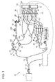
- One light (that is, measurement light) split by the PM coupler 14 is inputted to the measurement light generator (21 to 29, 31, 32).
- the PM coupler 21 divides the measurement light inputted from the PM coupler 14, into first measurement light and second measurement light.
- the first measurement light divided by the PM coupler 21 is guided to the measurement light path S1
- the second measurement light divided by the PM coupler 21 is guided to the measurement light path S2.
- the first measurement light guided to the measurement light path S1 is inputted through the optical path length difference generator 22 and the circulator 23 to the polarization beam combiner/splitter 25.
- the second measurement light guided to the measurement light path S2 is inputted through the circulator 24 to the polarization beam combiner/splitter 25.
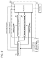
- the first interfering light detector 80 acquires first sampling data with respect to the interfering signals (interfering signal HH and interfering signal HV) inputted from the measurement part 10, based on a sampling clock 1 inputted from the measurement part 10, using a sampling trigger 1 as a trigger, and outputs the first sampling data to the processor 202.
- the processor 202 performs calculation processing such as Fourier transform processing on the first sampling data, to generate an HH tomographic image and an HV tomographic image.
- the sampling may be started with a delay from the sampling trigger 1 by a time corresponding to the optical path length difference ⁇ l.
- the sampling clock generator may be composed of a Mach-Zehnder interferometer, for example. As shown in FIG. 3 , the sampling clock generator generates a sampling clock with an equal frequency, using a Mach-Zehnder interferometer.
- the sampling clock generated by the Mach-Zehnder interferometer is inputted to a distributor 172.
- the distributor 172 distributes the sampling clock into the sampling clock 1 and the sampling clock 2.
- the sampling clock 1 is inputted through a signal delay circuit 174 to the first interfering light detector 80.
- the sampling clock 2 is directly inputted to the second interfering light detector 90.
- the signal delay circuit 174 is designed so as to cause a delay by a time corresponding to the optical path length difference ⁇ l of the optical path length difference generator 22.
- the optical tomographic device it is not necessary to divide the sampling frequency into two regions in order to perform signal processing of the interfering signals by the signal processors 83 and 93. Therefore, it is possible to sample the interfering signals up to the frequency at which the signal processors 83 and 93 can perform sampling.
- the depthwise measurement range can be doubled as compared to the optical tomographic device disclosed in Non-Patent Literature 1, for example.
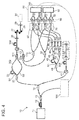
- the optical system of the optical tomographic device may be configured as shown in FIG. 5 .
- the optical tomographic device shown in FIG. 5 is different from the above embodiment in the configuration from the polarization beam combiner/splitter 25 to the subject 30 in FIG. 1 . That is, in this modification, a polarization beam splitter 404 is used instead of the polarization beam combiner/splitter 25.
- three reference light corresponding to these measurement light may be generated, and three interfering light generators and three interfering light detectors corresponding to the respective optical path lengths may be provided.
- a plurality of tomographic images can be acquired at the same position in a subject, and if these tomographic images are subjected to image processing such as addition processing, a tomographic image with a high contrast and an optimum SNR can be acquired.
- the PM coupler 21, the PM coupler 44, and the polarization beam combiner/splitter 25 are examples of the "first splitter”, the "second splitter”, and the "third splitter”, respectively.
Landscapes
- Health & Medical Sciences (AREA)
- Physics & Mathematics (AREA)
- Life Sciences & Earth Sciences (AREA)
- General Physics & Mathematics (AREA)
- General Health & Medical Sciences (AREA)
- Nuclear Medicine, Radiotherapy & Molecular Imaging (AREA)
- Radiology & Medical Imaging (AREA)
- Engineering & Computer Science (AREA)
- Biophysics (AREA)
- Molecular Biology (AREA)
- Veterinary Medicine (AREA)
- Public Health (AREA)
- Biomedical Technology (AREA)
- Heart & Thoracic Surgery (AREA)
- Medical Informatics (AREA)
- Animal Behavior & Ethology (AREA)
- Surgery (AREA)
- Optics & Photonics (AREA)
- Pathology (AREA)
- Automation & Control Theory (AREA)
- Ophthalmology & Optometry (AREA)
- Investigating Or Analysing Materials By Optical Means (AREA)
- Eye Examination Apparatus (AREA)
Claims (10)
- Dispositif tomographique optique configuré pour acquérir une image tomographique d'un sujet (30), le dispositif tomographique optique comprenant :une source de lumière (11) ;un générateur de lumière de mesure (21 à 29, 31, 32) adapté pour générer de la lumière de mesure en utilisant la lumière de la source de lumière (11), qui est irradiée sur le sujet et réfléchie par le sujet (30) ;un générateur de lumière de référence (41 à 46, 51) adapté pour générer de la lumière de référence en utilisant la lumière de la source de lumière (11) ;un générateur de lumière d'interférence (60, 70) adapté pour générer de la lumière d'interférence en combinant la lumière réfléchie, réfléchie par le sujet (30) et la lumière de référence générée dans le générateur de lumière de référence (41 à 46, 51) ; etun détecteur de lumière d'interférence (80, 90) adapté pour détecter la lumière d'interférence générée dans le générateur de lumière d'interférence (60, 70) et pour convertir la lumière d'interférence en signaux d'interférence ;dans lequel le générateur de lumière de mesure (21 à 29, 31, 32) est adapté pour générer au moins deux lumières de mesure ayant différentes longueurs de chemin optique, pour superposer les au moins deux lumières de mesure, pour irradier les au moins deux lumières de mesure superposées sur le sujet (30),le générateur de lumière de référence (41 à 46, 51) est adapté pour générer au moins deux lumières de référence ayant différentes longueurs de chemin optique,caractérisé en ce que
le générateur de lumière de mesure (21 à 29, 31, 32) est adapté pour diviser la lumière réfléchie, réfléchie par le sujet (30) en au moins deux lumières réfléchies, et pour guider les au moins deux lumières réfléchies divisées vers le générateur de d'interférence (60), (70) ; et en ce que
le générateur de lumière d'interférence (60, 70) inclut au moins deux générateurs de lumière d'interférence, chaque générateur de lumière d'interférence (60, 70) est configuré pour combiner une des au moins deux lumières réfléchies ayant des longueurs de chemin optique différentes guidées depuis le générateur de lumière de mesure (21 à 29, 31, 32) et la lumière correspondante des au moins deux lumières de référence ayant des longueurs de chemin optique différentes générées dans le générateur de lumière de référence (41 à 46, 51),
le détecteur de lumière d'interférence (80, 90) inclut au moins deux détecteurs de lumière d'interférence, chaque détecteur de lumière d'interférence (80, 90) est configuré pour détecter la lumière d'interférence générée dans le générateur correspondant des au moins deux générateurs de lumière d'interférence (60, 70) et convertir la lumière d'interférence détectée en le signal correspondant des au moins deux signaux d'interférence. - Dispositif tomographique optique selon la revendication 1, dans lequel
le générateur de lumière de mesure (21 à 29, 31, 32) comprend :un premier séparateur (21) adapté pour diviser la lumière de mesure de la source de lumière (11) en au moins deux chemins optiques (S1, S2) ; etun premier générateur de différence de longueur de chemin optique (22) placé sur l'au moins un des au moins deux chemins optiques (S1, S2) divisés par le premier séparateur (21), etle premier générateur de différence de longueur de chemin optique (22) est configuré pour générer une longueur de chemin optique différente entre les au moins deux chemins optiques (S1, S2). - Dispositif tomographique optique selon la revendication 2, dans lequel
le générateur de lumière de référence (41 à 46, 51) comprend :un deuxième séparateur (44) adapté pour diviser la lumière de référence de la source de lumière (11) en au moins deux chemins optiques (R1, R2) ; etun second générateur de différence de longueur de chemin optique (45) placé sur l'au moins un des au moins deux chemins optiques (R1, R2) divisé par le deuxième séparateur (44), etle second générateur de différence de longueur de chemin optique (45) est configuré pour générer une longueur de chemin optique différente entre les au moins deux chemins optiques (R1, R2). - Dispositif tomographique optique selon l'une quelconque des revendications 1 à 3, comprenant en outre :un processeur d'images (202) configuré pour générer une image tomographique optique à partir d'au moins deux images tomographiques optiques obtenues à partir des au moins deux signaux d'interférence obtenus par les au moins deux détecteurs de lumière d'interférence (80, 90).
- Dispositif tomographique optique selon la revendication 3, dans lequel
au moins une différence de longueurs de chemin optique entre les au moins deux chemins optiques (S1, S2) divisés dans le générateur de lumière de mesure (21 à 29, 31, 32) et au moins une différence de longueurs de chemin optique entre les au moins deux chemins optiques (R1, R2) divisés dans le générateur de lumière de référence (41 à 46, 51) sont la même différence. - Dispositif tomographique optique selon la revendication 3 ou 5, dans lequel
au moins une différence de longueurs de chemin optique entre les au moins deux chemins optiques (S1, S2) divisés dans le générateur de lumière de mesure (21 à 29, 31, 32) est plus longue qu'une distance dans le sens de la profondeur du sujet (30) devant être mesuré, et au moins une différence des longueurs de chemin optique entre les au moins deux chemins optiques (R1, R2) divisés dans le générateur de lumière de référence (41 à 46, 51) est plus longue que la distance dans le sens de la profondeur du sujet (30) devant être mesuré. - Dispositif tomographique optique selon l'une quelconque des revendications 1 à 6, dans lequel
des composants de polarisation de lumière dans au moins deux chemins optiques différents (S1, S2) divisés dans le générateur de lumière de mesure (21 à 29, 31, 32) sont différents les uns des autres. - Dispositif tomographique optique selon la revendication 7, dans lequel
les composants de polarisation de la lumière dans les au moins deux chemins optiques différents (S1, S2) divisés dans le générateur de lumière de mesure (21 à 29, 31, 32) incluent au moins une polarisation horizontale et une polarisation verticale. - Dispositif tomographique optique selon la revendication 7 ou 8, dans lequel
le premier séparateur (21) est adapté pour diviser la lumière de mesure de la source de lumière (11) en les au moins deux lumières dont les sens de polarisation sont différents l'un de l'autre ;
un troisième séparateur (25) adapté pour diviser la lumière réfléchie par le sujet (30) en les au moins deux lumières dont les sens de polarisation sont différents l'un de l'autre ; et
au moins l'un du premier séparateur (21) et du troisième séparateur (25) est un combinateur/séparateur de faisceaux de polarisation. - Dispositif tomographique optique selon l'une quelconque des revendications 1 à 9, dans lequel
au moins un chemin optique configurant un système optique du dispositif tomographique optique comprend une fibre de maintien de polarisation.
Applications Claiming Priority (1)
| Application Number | Priority Date | Filing Date | Title |
|---|---|---|---|
| JP2014184507A JP6463051B2 (ja) | 2014-09-10 | 2014-09-10 | 光断層画像撮影装置 |
Publications (2)
| Publication Number | Publication Date |
|---|---|
| EP2995245A1 EP2995245A1 (fr) | 2016-03-16 |
| EP2995245B1 true EP2995245B1 (fr) | 2016-11-30 |
Family
ID=54105687
Family Applications (1)
| Application Number | Title | Priority Date | Filing Date |
|---|---|---|---|
| EP15184557.5A Active EP2995245B1 (fr) | 2014-09-10 | 2015-09-09 | Dispositif tomographique optique |
Country Status (3)
| Country | Link |
|---|---|
| US (1) | US9593936B2 (fr) |
| EP (1) | EP2995245B1 (fr) |
| JP (1) | JP6463051B2 (fr) |
Families Citing this family (10)
| Publication number | Priority date | Publication date | Assignee | Title |
|---|---|---|---|---|
| JP6685673B2 (ja) * | 2015-05-01 | 2020-04-22 | キヤノン株式会社 | 撮像装置 |
| KR101882769B1 (ko) | 2016-08-04 | 2018-08-24 | 광주과학기술원 | 주파수 분할 다중화방식의 광단층 영상장치 |
| JP6766995B2 (ja) * | 2016-11-09 | 2020-10-14 | 株式会社ミツトヨ | 位相シフト干渉計 |
| JP7144822B2 (ja) | 2017-12-22 | 2022-09-30 | 株式会社トーメーコーポレーション | 光断層画像撮影装置 |
| JP6803887B2 (ja) * | 2018-10-10 | 2020-12-23 | 株式会社吉田製作所 | 光干渉断層画像生成装置 |
| JP7332131B2 (ja) * | 2019-03-27 | 2023-08-23 | 株式会社トーメーコーポレーション | 光断層画像撮影装置 |
| KR102377583B1 (ko) * | 2019-04-05 | 2022-03-22 | 미쓰비시덴키 가부시키가이샤 | 광 거리 측정 장치 |
| US11175126B2 (en) * | 2019-04-08 | 2021-11-16 | Canon U.S.A., Inc. | Automated polarization control |
| JP6987326B2 (ja) * | 2019-10-18 | 2021-12-22 | 三菱電機株式会社 | 光距離測定装置、及び加工装置 |
| JP2023084947A (ja) | 2021-12-08 | 2023-06-20 | 株式会社トーメーコーポレーション | 画像処理装置及びそれを備えた眼科装置 |
Family Cites Families (18)
| Publication number | Priority date | Publication date | Assignee | Title |
|---|---|---|---|---|
| JP2006215005A (ja) * | 2005-02-07 | 2006-08-17 | Fujinon Corp | 光断層画像化装置 |
| KR101387454B1 (ko) * | 2005-08-09 | 2014-04-22 | 더 제너럴 하스피탈 코포레이션 | 광간섭 단층촬영법에서 편광 기반 직교 복조를 수행하기위한 장치, 방법 및 저장 매체 |
| JP5135324B2 (ja) * | 2006-04-05 | 2013-02-06 | ザ ジェネラル ホスピタル コーポレイション | サンプルの偏光感応性光周波数領域画像形成のための方法、構成およびシステム |
| JP4344829B2 (ja) | 2006-05-02 | 2009-10-14 | 国立大学法人 筑波大学 | 偏光感受光画像計測装置 |
| JP5541831B2 (ja) * | 2006-12-07 | 2014-07-09 | 株式会社トプコン | 光断層画像化装置およびその作動方法 |
| GB0803559D0 (en) * | 2008-02-27 | 2008-04-02 | Univ Kent Canterbury | Multiple path intererometer and method |
| US7597565B1 (en) * | 2008-03-11 | 2009-10-06 | Textron Systems Corporation | Continuous sliding electrical contact tape |
| JP5558735B2 (ja) * | 2009-04-13 | 2014-07-23 | キヤノン株式会社 | 光断層撮像装置及びその制御方法 |
| JP5836564B2 (ja) * | 2010-03-12 | 2015-12-24 | キヤノン株式会社 | 眼科撮像装置、および眼科撮像方法、そのプログラム |
| JP5627321B2 (ja) * | 2010-07-09 | 2014-11-19 | キヤノン株式会社 | 光断層画像撮像装置及びその撮像方法 |
| US8947648B2 (en) * | 2011-03-06 | 2015-02-03 | Ninepoint Medical, Inc. | Systems and methods for signal processing in optical imaging systems |
| EP2574273B1 (fr) * | 2011-06-23 | 2014-09-24 | Nidek Co., Ltd. | Appareil tomographique de cohérence optique |
| JP5903903B2 (ja) * | 2012-01-19 | 2016-04-13 | 株式会社ニデック | 光コヒーレンストモグラフィー装置 |
| JP5905711B2 (ja) | 2011-11-25 | 2016-04-20 | 株式会社トプコン | 光画像計測装置 |
| JP2013160699A (ja) * | 2012-02-08 | 2013-08-19 | Hitachi High-Technologies Corp | 光断層画像測定装置 |
| JP2014206433A (ja) | 2013-04-12 | 2014-10-30 | 株式会社トーメーコーポレーション | 光断層画像撮影装置 |
| US9046339B2 (en) * | 2013-09-30 | 2015-06-02 | Carl Zeiss Meditec, Inc. | Systems and methods for bidirectional functional optical coherence tomography |
| JP2016002381A (ja) * | 2014-06-18 | 2016-01-12 | キヤノン株式会社 | 撮影装置及びその方法 |
-
2014
- 2014-09-10 JP JP2014184507A patent/JP6463051B2/ja active Active
-
2015
- 2015-09-09 EP EP15184557.5A patent/EP2995245B1/fr active Active
- 2015-09-10 US US14/849,860 patent/US9593936B2/en active Active
Non-Patent Citations (1)
| Title |
|---|
| None * |
Also Published As
| Publication number | Publication date |
|---|---|
| US9593936B2 (en) | 2017-03-14 |
| JP6463051B2 (ja) | 2019-01-30 |
| EP2995245A1 (fr) | 2016-03-16 |
| US20160069664A1 (en) | 2016-03-10 |
| JP2016057197A (ja) | 2016-04-21 |
Similar Documents
| Publication | Publication Date | Title |
|---|---|---|
| EP2995245B1 (fr) | Dispositif tomographique optique | |
| US9584098B2 (en) | Sample clock generator for optical tomographic imaging apparatus, and optical tomographic imaging apparatus | |
| EP3006918B1 (fr) | Système oct à matrice de jones et programme pour mettre en uvre un traitement d'image sur des données mesurées obtenues par ledit oct | |
| JP5939866B2 (ja) | 光干渉断層撮像装置及び撮像方法 | |
| US9060689B2 (en) | Apparatus, method and system for performing phase-resolved optical frequency domain imaging | |
| KR101387454B1 (ko) | 광간섭 단층촬영법에서 편광 기반 직교 복조를 수행하기위한 장치, 방법 및 저장 매체 | |
| US7929148B2 (en) | Optical coherence tomography implementation apparatus and method of use | |
| US9354038B2 (en) | Swept source optical coherence tomography and method for stabilizing phase thereof | |
| EP3239651B1 (fr) | Stabilisation de phase de tomographie par cohérence optique de source à balayage (ss-oct) avec étalonnage de signal de référence | |
| US9918623B2 (en) | Optical tomographic imaging apparatus | |
| BR112018001315B1 (pt) | Sistema de interferometria e método | |
| JP5869616B2 (ja) | K−クロックを用いた周波数ドメインoctのインターフェログラムの誤サンプリングの検出 | |
| KR101706448B1 (ko) | 밸런싱 디텍팅 듀얼 광 결맞음 영상 장치 | |
| JP2014092425A (ja) | 光干渉断層撮像装置及び光干渉断層撮像方法 | |
| JP2016083245A (ja) | 光断層撮影装置 | |
| JP6601189B2 (ja) | 光コヒーレンストモグラフィ装置および干渉信号処理プログラム | |
| KR20160117814A (ko) | 밸런싱 디텍팅 광 결맞음 영상 장치 | |
| Sekhar et al. | Theoretical analysis of complex-conjugate-ambiguity suppression in frequency-domain optical-coherence tomography | |
| JP2016007245A (ja) | 光断層画像撮影装置 | |
| JP2017201257A (ja) | 光断層像撮影装置 |
Legal Events
| Date | Code | Title | Description |
|---|---|---|---|
| PUAI | Public reference made under article 153(3) epc to a published international application that has entered the european phase |
Free format text: ORIGINAL CODE: 0009012 |
|
| AK | Designated contracting states |
Kind code of ref document: A1 Designated state(s): AL AT BE BG CH CY CZ DE DK EE ES FI FR GB GR HR HU IE IS IT LI LT LU LV MC MK MT NL NO PL PT RO RS SE SI SK SM TR |
|
| AX | Request for extension of the european patent |
Extension state: BA ME |
|
| 17P | Request for examination filed |
Effective date: 20160429 |
|
| RBV | Designated contracting states (corrected) |
Designated state(s): AL AT BE BG CH CY CZ DE DK EE ES FI FR GB GR HR HU IE IS IT LI LT LU LV MC MK MT NL NO PL PT RO RS SE SI SK SM TR |
|
| GRAP | Despatch of communication of intention to grant a patent |
Free format text: ORIGINAL CODE: EPIDOSNIGR1 |
|
| RIC1 | Information provided on ipc code assigned before grant |
Ipc: A61B 5/00 20060101AFI20160603BHEP Ipc: G01B 9/02 20060101ALI20160603BHEP Ipc: A61B 3/10 20060101ALI20160603BHEP Ipc: H04R 25/00 20060101ALI20160603BHEP |
|
| INTG | Intention to grant announced |
Effective date: 20160621 |
|
| GRAS | Grant fee paid |
Free format text: ORIGINAL CODE: EPIDOSNIGR3 |
|
| GRAA | (expected) grant |
Free format text: ORIGINAL CODE: 0009210 |
|
| AK | Designated contracting states |
Kind code of ref document: B1 Designated state(s): AL AT BE BG CH CY CZ DE DK EE ES FI FR GB GR HR HU IE IS IT LI LT LU LV MC MK MT NL NO PL PT RO RS SE SI SK SM TR |
|
| REG | Reference to a national code |
Ref country code: CH Ref legal event code: EP Ref country code: GB Ref legal event code: FG4D |
|
| REG | Reference to a national code |
Ref country code: AT Ref legal event code: REF Ref document number: 849027 Country of ref document: AT Kind code of ref document: T Effective date: 20161215 |
|
| REG | Reference to a national code |
Ref country code: IE Ref legal event code: FG4D |
|
| REG | Reference to a national code |
Ref country code: DE Ref legal event code: R096 Ref document number: 602015000861 Country of ref document: DE |
|
| PG25 | Lapsed in a contracting state [announced via postgrant information from national office to epo] |
Ref country code: LV Free format text: LAPSE BECAUSE OF FAILURE TO SUBMIT A TRANSLATION OF THE DESCRIPTION OR TO PAY THE FEE WITHIN THE PRESCRIBED TIME-LIMIT Effective date: 20161130 |
|
| REG | Reference to a national code |
Ref country code: LT Ref legal event code: MG4D |
|
| REG | Reference to a national code |
Ref country code: NL Ref legal event code: MP Effective date: 20161130 |
|
| REG | Reference to a national code |
Ref country code: AT Ref legal event code: MK05 Ref document number: 849027 Country of ref document: AT Kind code of ref document: T Effective date: 20161130 |
|
| PG25 | Lapsed in a contracting state [announced via postgrant information from national office to epo] |
Ref country code: GR Free format text: LAPSE BECAUSE OF FAILURE TO SUBMIT A TRANSLATION OF THE DESCRIPTION OR TO PAY THE FEE WITHIN THE PRESCRIBED TIME-LIMIT Effective date: 20170301 Ref country code: SE Free format text: LAPSE BECAUSE OF FAILURE TO SUBMIT A TRANSLATION OF THE DESCRIPTION OR TO PAY THE FEE WITHIN THE PRESCRIBED TIME-LIMIT Effective date: 20161130 Ref country code: LT Free format text: LAPSE BECAUSE OF FAILURE TO SUBMIT A TRANSLATION OF THE DESCRIPTION OR TO PAY THE FEE WITHIN THE PRESCRIBED TIME-LIMIT Effective date: 20161130 Ref country code: NO Free format text: LAPSE BECAUSE OF FAILURE TO SUBMIT A TRANSLATION OF THE DESCRIPTION OR TO PAY THE FEE WITHIN THE PRESCRIBED TIME-LIMIT Effective date: 20170228 |
|
| PG25 | Lapsed in a contracting state [announced via postgrant information from national office to epo] |
Ref country code: AT Free format text: LAPSE BECAUSE OF FAILURE TO SUBMIT A TRANSLATION OF THE DESCRIPTION OR TO PAY THE FEE WITHIN THE PRESCRIBED TIME-LIMIT Effective date: 20161130 Ref country code: FI Free format text: LAPSE BECAUSE OF FAILURE TO SUBMIT A TRANSLATION OF THE DESCRIPTION OR TO PAY THE FEE WITHIN THE PRESCRIBED TIME-LIMIT Effective date: 20161130 Ref country code: RS Free format text: LAPSE BECAUSE OF FAILURE TO SUBMIT A TRANSLATION OF THE DESCRIPTION OR TO PAY THE FEE WITHIN THE PRESCRIBED TIME-LIMIT Effective date: 20161130 Ref country code: PL Free format text: LAPSE BECAUSE OF FAILURE TO SUBMIT A TRANSLATION OF THE DESCRIPTION OR TO PAY THE FEE WITHIN THE PRESCRIBED TIME-LIMIT Effective date: 20161130 Ref country code: HR Free format text: LAPSE BECAUSE OF FAILURE TO SUBMIT A TRANSLATION OF THE DESCRIPTION OR TO PAY THE FEE WITHIN THE PRESCRIBED TIME-LIMIT Effective date: 20161130 Ref country code: ES Free format text: LAPSE BECAUSE OF FAILURE TO SUBMIT A TRANSLATION OF THE DESCRIPTION OR TO PAY THE FEE WITHIN THE PRESCRIBED TIME-LIMIT Effective date: 20161130 Ref country code: PT Free format text: LAPSE BECAUSE OF FAILURE TO SUBMIT A TRANSLATION OF THE DESCRIPTION OR TO PAY THE FEE WITHIN THE PRESCRIBED TIME-LIMIT Effective date: 20170330 |
|
| PG25 | Lapsed in a contracting state [announced via postgrant information from national office to epo] |
Ref country code: NL Free format text: LAPSE BECAUSE OF FAILURE TO SUBMIT A TRANSLATION OF THE DESCRIPTION OR TO PAY THE FEE WITHIN THE PRESCRIBED TIME-LIMIT Effective date: 20161130 |
|
| PG25 | Lapsed in a contracting state [announced via postgrant information from national office to epo] |
Ref country code: EE Free format text: LAPSE BECAUSE OF FAILURE TO SUBMIT A TRANSLATION OF THE DESCRIPTION OR TO PAY THE FEE WITHIN THE PRESCRIBED TIME-LIMIT Effective date: 20161130 Ref country code: CZ Free format text: LAPSE BECAUSE OF FAILURE TO SUBMIT A TRANSLATION OF THE DESCRIPTION OR TO PAY THE FEE WITHIN THE PRESCRIBED TIME-LIMIT Effective date: 20161130 Ref country code: DK Free format text: LAPSE BECAUSE OF FAILURE TO SUBMIT A TRANSLATION OF THE DESCRIPTION OR TO PAY THE FEE WITHIN THE PRESCRIBED TIME-LIMIT Effective date: 20161130 Ref country code: RO Free format text: LAPSE BECAUSE OF FAILURE TO SUBMIT A TRANSLATION OF THE DESCRIPTION OR TO PAY THE FEE WITHIN THE PRESCRIBED TIME-LIMIT Effective date: 20161130 Ref country code: SK Free format text: LAPSE BECAUSE OF FAILURE TO SUBMIT A TRANSLATION OF THE DESCRIPTION OR TO PAY THE FEE WITHIN THE PRESCRIBED TIME-LIMIT Effective date: 20161130 |
|
| PG25 | Lapsed in a contracting state [announced via postgrant information from national office to epo] |
Ref country code: BE Free format text: LAPSE BECAUSE OF FAILURE TO SUBMIT A TRANSLATION OF THE DESCRIPTION OR TO PAY THE FEE WITHIN THE PRESCRIBED TIME-LIMIT Effective date: 20161130 Ref country code: IT Free format text: LAPSE BECAUSE OF FAILURE TO SUBMIT A TRANSLATION OF THE DESCRIPTION OR TO PAY THE FEE WITHIN THE PRESCRIBED TIME-LIMIT Effective date: 20161130 Ref country code: BG Free format text: LAPSE BECAUSE OF FAILURE TO SUBMIT A TRANSLATION OF THE DESCRIPTION OR TO PAY THE FEE WITHIN THE PRESCRIBED TIME-LIMIT Effective date: 20170228 Ref country code: SM Free format text: LAPSE BECAUSE OF FAILURE TO SUBMIT A TRANSLATION OF THE DESCRIPTION OR TO PAY THE FEE WITHIN THE PRESCRIBED TIME-LIMIT Effective date: 20161130 |
|
| REG | Reference to a national code |
Ref country code: DE Ref legal event code: R097 Ref document number: 602015000861 Country of ref document: DE |
|
| REG | Reference to a national code |
Ref country code: FR Ref legal event code: PLFP Year of fee payment: 3 |
|
| PLBE | No opposition filed within time limit |
Free format text: ORIGINAL CODE: 0009261 |
|
| STAA | Information on the status of an ep patent application or granted ep patent |
Free format text: STATUS: NO OPPOSITION FILED WITHIN TIME LIMIT |
|
| 26N | No opposition filed |
Effective date: 20170831 |
|
| PG25 | Lapsed in a contracting state [announced via postgrant information from national office to epo] |
Ref country code: SI Free format text: LAPSE BECAUSE OF FAILURE TO SUBMIT A TRANSLATION OF THE DESCRIPTION OR TO PAY THE FEE WITHIN THE PRESCRIBED TIME-LIMIT Effective date: 20161130 |
|
| PG25 | Lapsed in a contracting state [announced via postgrant information from national office to epo] |
Ref country code: MC Free format text: LAPSE BECAUSE OF FAILURE TO SUBMIT A TRANSLATION OF THE DESCRIPTION OR TO PAY THE FEE WITHIN THE PRESCRIBED TIME-LIMIT Effective date: 20161130 |
|
| REG | Reference to a national code |
Ref country code: IE Ref legal event code: MM4A |
|
| PG25 | Lapsed in a contracting state [announced via postgrant information from national office to epo] |
Ref country code: LU Free format text: LAPSE BECAUSE OF NON-PAYMENT OF DUE FEES Effective date: 20170909 |
|
| PG25 | Lapsed in a contracting state [announced via postgrant information from national office to epo] |
Ref country code: IE Free format text: LAPSE BECAUSE OF NON-PAYMENT OF DUE FEES Effective date: 20170909 |
|
| REG | Reference to a national code |
Ref country code: FR Ref legal event code: PLFP Year of fee payment: 4 |
|
| PG25 | Lapsed in a contracting state [announced via postgrant information from national office to epo] |
Ref country code: MT Free format text: LAPSE BECAUSE OF NON-PAYMENT OF DUE FEES Effective date: 20170909 |
|
| REG | Reference to a national code |
Ref country code: CH Ref legal event code: PL |
|
| PG25 | Lapsed in a contracting state [announced via postgrant information from national office to epo] |
Ref country code: HU Free format text: LAPSE BECAUSE OF FAILURE TO SUBMIT A TRANSLATION OF THE DESCRIPTION OR TO PAY THE FEE WITHIN THE PRESCRIBED TIME-LIMIT; INVALID AB INITIO Effective date: 20150909 |
|
| PG25 | Lapsed in a contracting state [announced via postgrant information from national office to epo] |
Ref country code: LI Free format text: LAPSE BECAUSE OF NON-PAYMENT OF DUE FEES Effective date: 20180930 Ref country code: CH Free format text: LAPSE BECAUSE OF NON-PAYMENT OF DUE FEES Effective date: 20180930 |
|
| PG25 | Lapsed in a contracting state [announced via postgrant information from national office to epo] |
Ref country code: CY Free format text: LAPSE BECAUSE OF FAILURE TO SUBMIT A TRANSLATION OF THE DESCRIPTION OR TO PAY THE FEE WITHIN THE PRESCRIBED TIME-LIMIT Effective date: 20161130 |
|
| PG25 | Lapsed in a contracting state [announced via postgrant information from national office to epo] |
Ref country code: MK Free format text: LAPSE BECAUSE OF FAILURE TO SUBMIT A TRANSLATION OF THE DESCRIPTION OR TO PAY THE FEE WITHIN THE PRESCRIBED TIME-LIMIT Effective date: 20161130 |
|
| PG25 | Lapsed in a contracting state [announced via postgrant information from national office to epo] |
Ref country code: TR Free format text: LAPSE BECAUSE OF FAILURE TO SUBMIT A TRANSLATION OF THE DESCRIPTION OR TO PAY THE FEE WITHIN THE PRESCRIBED TIME-LIMIT Effective date: 20161130 |
|
| PG25 | Lapsed in a contracting state [announced via postgrant information from national office to epo] |
Ref country code: AL Free format text: LAPSE BECAUSE OF FAILURE TO SUBMIT A TRANSLATION OF THE DESCRIPTION OR TO PAY THE FEE WITHIN THE PRESCRIBED TIME-LIMIT Effective date: 20161130 Ref country code: IS Free format text: LAPSE BECAUSE OF FAILURE TO SUBMIT A TRANSLATION OF THE DESCRIPTION OR TO PAY THE FEE WITHIN THE PRESCRIBED TIME-LIMIT Effective date: 20170330 |
|
| P01 | Opt-out of the competence of the unified patent court (upc) registered |
Effective date: 20230515 |
|
| PGFP | Annual fee paid to national office [announced via postgrant information from national office to epo] |
Ref country code: GB Payment date: 20230727 Year of fee payment: 9 |
|
| PGFP | Annual fee paid to national office [announced via postgrant information from national office to epo] |
Ref country code: FR Payment date: 20230808 Year of fee payment: 9 Ref country code: DE Payment date: 20230802 Year of fee payment: 9 |