EP2995182B2 - Kopfstangenanordnung und verfahren zu deren verwendung - Google Patents
Kopfstangenanordnung und verfahren zu deren verwendung Download PDFInfo
- Publication number
- EP2995182B2 EP2995182B2 EP15184414.9A EP15184414A EP2995182B2 EP 2995182 B2 EP2995182 B2 EP 2995182B2 EP 15184414 A EP15184414 A EP 15184414A EP 2995182 B2 EP2995182 B2 EP 2995182B2
- Authority
- EP
- European Patent Office
- Prior art keywords
- header bar
- wing
- bar section
- moveable
- pillar
- Prior art date
- Legal status (The legal status is an assumption and is not a legal conclusion. Google has not performed a legal analysis and makes no representation as to the accuracy of the status listed.)
- Active
Links
Images


Classifications
-
- A—HUMAN NECESSITIES
- A01—AGRICULTURE; FORESTRY; ANIMAL HUSBANDRY; HUNTING; TRAPPING; FISHING
- A01D—HARVESTING; MOWING
- A01D41/00—Combines, i.e. harvesters or mowers combined with threshing devices
- A01D41/12—Details of combines
- A01D41/14—Mowing tables
- A01D41/144—Foldable headers
-
- A—HUMAN NECESSITIES
- A01—AGRICULTURE; FORESTRY; ANIMAL HUSBANDRY; HUNTING; TRAPPING; FISHING
- A01B—SOIL WORKING IN AGRICULTURE OR FORESTRY; PARTS, DETAILS, OR ACCESSORIES OF AGRICULTURAL MACHINES OR IMPLEMENTS, IN GENERAL
- A01B73/00—Means or arrangements to facilitate transportation of agricultural machines or implements, e.g. folding frames to reduce overall width
- A01B73/02—Folding frames
- A01B73/06—Folding frames foldable about a vertical axis
Definitions
- the invention concerns a header bar assembly and a method of its use.
- the invention also relates to a vehicle including a header bar.
- header bar assemblies Most commonly they are encountered in combine harvesters, although variants on the basic design of header bar are also found in other harvesting vehicles such as beet harvesters, pea/bean harvesters and forage harvesters.
- the invention is applicable in all types of harvesting machine as are summarised above.
- the header bar assembly comprises a number of row units, placed side by side and each being arranged for harvesting a row of corn plants.
- Corn plants are typically planted in rows spaced a predetermined distance apart.
- Row units of corn headers are spaced a corresponding distance apart so as to be capable of following the rows while inducting the corn plants.
- the row units of the header are typically preceded by row dividers that separate the adjacent rows of plants for harvesting by the respective row units.
- the row units are configured and operable for receiving the stalks of the corn plants of the respective rows in succession, and removing the full or intact ears of corn, for conveying by other apparatus from the header to processing apparatus within the harvesting machine.
- the row units can comprise a variety of devices operable for harvesting the corn ears from the stalks, including deck plates defining a stalk receiving channel, gathering chains having teeth operable for carrying the corn ears rearward to a conveying apparatus of the header and snapping rolls located in association with the deck plates for pulling the corn stalks downwardly.
- the gathering chains are located above the deck plates and the snapping rolls are located below.
- the snapping rolls are rotatable for pulling the corn stalk downwardly, through rearward moving fingers of the gathering chains, to bring the ears to bear against the top edges of the deck plates so as to be detached from the stalks thereby.
- the detached ears are then carried toward the rear of the header by the gathering chains for conveying by other apparatus into the harvesting machine, while the collapsed stalks are left on the field.
- the header bar assembly is considerably wider than the body of the vehicle. This is so that the harvesting machine can harvest multiple rows of crop at a time, without the capacity of the machine being limited by the width of the vehicle body.
- header bar designs therefore is a significant advantage from the standpoint of harvesting efficiency, but it represents a drawback when the harvesting vehicle is required to travel on roads (as is commonly the case e.g. at the end of a working shift or when the harvester is required to move from one farm to another).
- header bar assembly is significantly wider than a typical road carriageway.
- a harvesting machine travelling on a road with a header bar assembly extending laterally as is required during harvesting operations would be entirely impractical since the header bar assembly would foul on objects at the side of the road, and the passage of other vehicles would be impeded by the length of the header bar that extends out of the carriageway in which the harvesting machine is moving.
- many narrow rural roads would be impenetrable to a harvesting machine having its header bar configured for harvesting operations.
- header bar assembly In some corn header designs it is known for the header bar assembly to be segmented, with sections known as "wings" at each end of the header bar assembly being pivotable along a vertically extending arc to overlie a mid-section during on-road driving of the harvesting machine. Regulatory requirements in many European countries dictate that when folded up in this way the maximum width of the header bar assembly must not exceed 3.5 m. Movement of the wings to the stowed position requires their inversion.
- each wing is significant. This means that the components that support them and transfer drive to them during their inversion and rotation must be robust and heavy. The power requirement for folding the wings is high, and the folding operation may be relatively slow to complete.
- EP 1932416 A1 proposes a different solution to the problem of header bar width.
- the harvester disclosed in this document includes a segmented header bar assembly in which wings including reel segments are pivotable about vertical axes so as to protrude forwardly of a fixed central header bar section when the harvester is required to travel on roads.
- Motor drives are provided for rotating the wings in a horizontal arc.
- the wings in their folded configuration are cantilevered forwardly from the fixed header bar section.
- header bar and the remainder of the vehicle must be carefully designed since otherwise the centre of mass of the vehicle may shift undesirably as conversion between the harvesting and driving configurations takes place. This may cause the harvester to behave in ways that are unfamiliar to an operator e.g. when driving on roads.
- the arc described by the wings as they move between the folded and deployed positions is large. It is necessary for the harvester operator to clear a large area near the front of the harvester of obstructions and people before converting the machine between its two main configurations.
- a header bar assembly comprising a row of header bar elements mounted on a fixed header bar section, the assembly including at at least a first end of the fixed header bar section a first moveable wing having mounted thereon one or more further header bar elements, the fixed header bar section supporting at the first end a first pillar extending generally perpendicular to the fixed header bar section and via which the first moveable wing is retained moveably captive relative to the fixed header bar section, the first moveable wing being moveable relative to the first pillar vertically and rotatably from an operative, deployed position in which it extends generally parallel to the fixed header bar section to a stowed position through:
- An advantage of this arrangement is that by moving the wings vertically as part of a stowing movement there is a reduced danger, compared with prior art header bars, of the wing striking an object at ground level during subsequent rotations even when, as in preferred embodiments of the invention, the rotations are through horizontal arcs.
- references to a header bar section that is "fixed” are relative. As a consequence it is not essential that the fixed header bar section is completely immovable relative to the remainder of the harvester; and instead the term may embrace within its scope e.g. a moveable partly flexible header bar section that while in use remaining generally in the same location may nonetheless be raised and lowered, or may flex, to accommodate ground undulations or objects that it strikes.
- the header bar assembly includes at a second end of the fixed header bar section opposite the first end a second moveable wing having mounted thereon one or more further header bar elements, the fixed header bar section supporting at the second end a second pillar extending generally perpendicular to the fixed header bar section and via which the second moveable wing is retained moveably captive relative to the fixed header bar section, the second moveable wing being moveable relative to the second pillar vertically and rotatably from an operative, deployed position in which it extends generally parallel to the fixed header bar section to a stowed position through vertical movement on the second pillar and rotation such that the second wing lies adjacent the fixed header bar section inboard of the second pillar.
- the header bar assembly may be made as a symmetrical structure in which a respective moveable wing is located at each end of an elongate, central fixed header bar section.
- the rotations of the or each wing are through horizontal arcs.
- the or each said pillar extends vertically upwardly relative to the fixed header bar section and indeed preferably is directly vertically extending. This assures the vertical initial movement of the or each wing on the pillar during movement from the deployed to the stowed configuration. Moreover in the stowed position the or each wing may readily be arranged to overlie an adjacent length of the fixed header bar section in a compact arrangement.
- each said moveable wing is moveable from its stowed position to its deployed position through horizontal rotation relative to its associated said pillar away from the fixed header bar section, vertical movement on the said pillar and further horizontal rotation such that the moveable wing lies parallel to the fixed header bar section extending from a said end thereof.
- the header assembly includes a drive mechanism for causing movement of at least one said header bar element and at least one said further header bar element relative to the header bar, the header bar assembly including a respective drive coupler/decoupler disengaging the drive mechanism from the or each said further header bar element upon, during or before: (i) movement of the associated said wing between the deployed position and the stowed position; (ii) rotation of the associated said wing out of parallel with the fixed header bar section; (iii) vertical movement of the associated said wing; or (iv) rotation of the associated said wing such that the associated said wing lies adjacent the fixed header bar section inboard of the associated said pillar.
- the drive coupler/decoupler couples the drive mechanism to the further header bar elements of the or each said moveable wing when the or each said moveable wing lies parallel to the fixed header bar section extending from a said end thereof.
- the arrangement of the invention therefore permits the application of (for example but not necessarily) rotational drive to one or more header bar elements supported by the wings when the latter are deployed, while permitting disengagement of such drive when it is required to stow the wings for road driving
- the header bar assembly of the invention includes one or more motors connected to effect movement of the or each said moveable wing, for example vertical movement and / or rotational movement and / or any other movement of the or each said moveable wing.
- the motors can be dedicated to the provision of wing movement as described; or they can be multi-purpose.
- drive to effect wing movement may be by way of a power take-off from the engine of the harvester.
- each said wing is less than half the length of the fixed header bar section. This means that both wings when stowed may be accommodated overlying the fixed header bar section.
- the row of header bar elements may comprise forwardly projecting elements, which may be for engaging a crop to be harvested.
- the invention resides in a method of stowing a moveable wing of a header bar assembly according to the invention as defined hereinabove comprising the steps of causing rotation of a said moveable wing out of parallel with the fixed header bar section; causing vertical movement of the said moveable wing on a said pillar; and causing further rotation of the said moveable wing such that the moveable wing lies adjacent the fixed header bar section inboard of the said pillar.
- the method of the invention preferably includes the step of causing disengagement of a drive mechanism for effecting movement of one or more said further header bar elements. This may conveniently be achieved through use of a coupler/decoupler as referred to above.
- the invention additionally or alternatively includes a method of causing deployment from a stowed position to an operative position of a moveable wing of a header bar assembly according to the invention as defined hereinabove comprising the steps of causing rotation of the said moveable wing such that the moveable wing lies skewed relative to the fixed header bar section and extending therefrom; causing vertical movement of the said moveable wing on a said pillar; and causing further rotation of the moveable wing until it lies generally parallel with the fixed header bar section extending from an end thereof.
- the method includes the step of causing engagement of a drive mechanism for effecting movement of one or more said further header bar elements relative to the header bar.
- the invention furthermore relates to a vehicle including a header bar assembly as defined herein.
- the vehicle may include one or more sensors of the position of a said wing relative to the fixed header bar section, and optionally may also include one or more audible and/or visual indicators of the status of a said sensor.
- a header bar assembly 10 of a harvesting vehicle (the remainder of which for ease of illustration is omitted from the drawings) includes a horizontal central header bar section 16 or similar structure having projecting forwardly (as judged with reference to the normal forward and rearward directions of motion of the harvesting vehicle) a series of header bar elements.
- row units 12 which may also be referred to as corn heads.
- the header bar elements could be, for example, tines, knives, scissors or comb teeth.
- the header bar assembly 10 includes a respective moveable wing 13, 14 each having mounted thereon one or more of the row units 12 so as to project forwardly in like manner to the remainder of the row units 12.
- Each wing 13, 14 may be considered as a parallel lateral extension of the central header bar section 16.
- the arrangement therefore is that the header bar assembly 10 includes the central, fixed header bar section 16 that is flanked at either end by a respective moveable header bar section partly defining each wing 13, 14.
- the pillar 18 in each case takes the form of a vertical, rigid cylindrical rod although this aspect of the invention may take a range of forms in other embodiments.
- Each wing 13, 14 is retained moveably captive relative to the fixed header bar section 16 e.g. by means of a further bracket that at one end is rigidly secured to the associated wing 13, 14 and at the opposite end terminates in an eye that encircles the pillar 18 so as to provide for moveable retention of each wing relative to the fixed header bar section 16.
- each wing 13, 14 is moveable both by rotating around the adjacent pillar 18 and through vertical sliding movement relative to the pillar, between a deployed position in which it is correctly located for harvesting operations and a stowed position that renders the header bar assembly more compact and hence makes the harvesting vehicle safe for road driving.
- the harvesting vehicle including the header bar assembly 10 includes means for providing driving power to the row units 12 or other header bar elements that are required to move during harvesting activity.
- driving power is provided by one or more drives such as shafts that couple rotational energy of the vehicle engine to the header bar elements.
- the header bar assembly 10 includes a respective coupler/decoupler that for ease of understanding is not shown in the drawings.
- the purpose of the coupler/decoupler is to couple rotational drive, on a selective basis, to the header bar elements of the wings 13, 14.
- the couplers/decouplers may be provided as clutches to engage/disengage a drive mechanism mounted on the 12 respective wings 13, 14. Such a clutch may be a spring operated claw clutch.
- the couplers/decouplers may disengage a drive mechanism from the row units 12 mounted on the respective wings 13, 14 upon, during or before: (i) rotation of the wing 13, 14 out of parallel with the fixed header bar section 16; (ii) vertical movement of the wing 13, 14; or (iii) any other movement of the wing 13, 14 between the deployed position and the stowed position.
- the header bar assembly 10 includes one or more motors or drive transfer arrangements for providing power to move the wings as described below. A first stage of movement is shown using dotted lines in respect of one of the wings 14 in Figure 1 .
- both wings 13, 14 would be moved, optionally simultaneously, following activation of a single control element such as a cab-mounted lever or button in order to energise the motors or other drive transfer arrangements in order to alter the header bar from a deployed to a stowed configuration.
- a single control element such as a cab-mounted lever or button
- each wing In the first stage of movement of each wing as shown in Figure 1 the wing is rotated rearwardly in a horizontal arc relative to its deployed position out of parallel with the fixed header bar section 16. This causes or enables disconnection of the drive to the row units 12 mounted on the wings, through operation of the coupler/decoupler that acts automatically to engage and disengage the drive as required.
- Such rotation as noted may be effected using e.g. dedicated motors or further engine power take-off features.
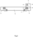
- each wing 13, 14 is raised vertically on the associated pillar under the influence of the motors, etc described above. This stage brings the underside of each wing 13, 14 clear of the top of the fixed header bar section 16. It then is possible for the wings 13, 14 to be rotated in the opposite direction to the initial, decoupling rotation until they overlie the fixed header bar section 16 as illustrated with respect to the right hand wing 14 in Figure 3 .
- the first stage of movement can be dispensed with when the decoupling of the drive elements and other connections between the central header bar section 16 and the wings 13, 14 can be realized with the wing 13, 14 still in its 'deployed' position, parallel to the central header bar section 16.
- This may, for example, be realized by using remotely retractable coupling mechanisms.
- the header bar assembly When thus configured on both sides the header bar assembly is compact and the harvesting vehicle therefore is suited for road driving. Movement from the deployed configuration of Figure 1 to the stowed configuration of Figure 3 is achieved without having to invert the wings. As a result the power and weight requirements of the header bar assembly 10 of the invention are less than those of the prior art arrangements.
- the wings however in the stowed position nonetheless overlie the fixed header bar section with the result that the centre of mass of the harvesting vehicle is essentially the same whether the header bar assembly 10 is configured for harvesting or road driving.
- no parts of the header bar assembly 10 protrude forwardly any further than when the assembly 10 is configured for harvesting.
- the sum of the width of the two wings 13, 14 does not need to be less than the width of the fixed header bar section 16.
- this can mean that the width of each of the wings 13, 14 is not restricted such that it must be less than half the width of the fixed header bar section 16.
- the wings 13, 14 are located above the fixed header bar section 16 in a rotated orientation and therefore the width of the wings 13, 14 does not cause them to interfere with one another.
- the width of the wings 13, 14, and therefore also the number of row units 12 that can be accommodated on the wings 13, 14 does not affect the transport width of the harvesting vehicle when the header bar 10 is folded for a road mode.
- a further benefit of the invention is that when rotating forwardly on the pillars the wings 13, 14 are in a raised position by reason of the vertical movement. This reduces the need for the harvesting machine to be on completely flat ground and/or for all objects in front of the header bar 10 to be cleared before conversion of the header bar commences.
- each wing 13, 14 initially rotates until it adopts the orientation visible in Figure 1 before descending on the pillar 18 to its lowermost position. From this location each wing rotates in the opposite direction to that of its initial movement in order to align the wing-mounted row units for harvesting and simultaneously engage drive to them by way of the coupler/decoupler. The harvesting vehicle is then ready to undertake harvesting by moving forwardly through rows of crops.
- a vehicle that includes a header bar assembly such as the one described above may also include one or more sensors of the position of one or both of the wings 13, 14 relative to the fixed header bar section 16.
- the vehicle may also include one or more audible and/or visual indicators of the status of a said sensor.
- Such sensors can beneficially be used to advise an operator of whether the wings 13, 14 are in the deployed position or the stowed position, thereby reducing the likelihood of the operator making a driving manoeuvre that is unsuitable for the position of the wings 13, 14.
Landscapes
- Life Sciences & Earth Sciences (AREA)
- Environmental Sciences (AREA)
- Engineering & Computer Science (AREA)
- Mechanical Engineering (AREA)
- Soil Sciences (AREA)
- Guiding Agricultural Machines (AREA)
- Agricultural Machines (AREA)
- Harvesting Machines For Specific Crops (AREA)
Claims (13)
- Vorsatzbalkenanordnung (10) mit einer Reihe von Vorsatzbalkenelementen (12), die an einem festen Vorsatzbalkenabschnitt (16) befestigt sind, wobei die Anordnung (10) zumindest an einem ersten Ende des festen Vorsatzbalkenabschnitts einen ersten beweglichen Flügel (14) mit einem oder mehreren daran befestigten weiteren Vorsatzbalkenelementen (12) umfasst, dadurch gekennzeichnet, dass der feste Vorsatzbalkenabschnitt (16) am ersten Ende eine erste Stütze (18) trägt, die sich im Allgemeinen senkrecht zum festen Vorsatzbalkenabschnitt (16) erstreckt und mittels derer der erste bewegliche Flügel (14) relativ zum festen Vorsatzbalkenabschnitt (16) beweglich sicher gehalten wird, wobei der erste bewegliche Flügel (14) aus einer betriebsbereiten Einsatzstellung, in der er sich hauptsächlich parallel zum festen Vorsatzbalkenabschnitt (16) erstreckt, in eine Verladestellung relativ zur ersten Stütze (18) vertikal und rotatorisch bewegbar ist durch:Drehung des beweglichen Flügels (14) aus der Parallelen zum festen Vorsatzbalkenabschnitt (16),vertikale Bewegung an der ersten Stütze (18), undweitere Drehung derart, dass der erste bewegliche Flügel (14) neben dem festen Vorsatzbalkenabschnitt (16) innerhalb der ersten Stütze (18) liegt.
- Vorsatzbalkenanordnung (10) nach Anspruch 1, mit einem zweiten beweglichen Flügel (13) mit einem oder mehreren weiteren daran befestigten Vorsatzbalkenelementen (12) an einem zweiten Ende des festen Vorsatzbalkenabschnitts (16) gegenüber dem ersten Ende, wobei der feste Vorsatzbalkenabschnitt (16) an dem zweiten Ende eine zweite Stütze (18) trägt, die sich im Allgemeinen senkrecht zum festen Vorsatzbalkenabschnitt (16) erstreckt und mittels derer der zweite bewegliche Flügel (13) relativ zum festen Vorsatzbalkenabschnitt (16) beweglich sicher gehalten wird, wobei der zweite bewegliche Flügel (13) aus einer betriebsbereiten Einsatzstellung, in der er sich hauptsächlich parallel zum festen Vorsatzbalkenabschnitt (16) erstreckt, in eine Verladestellung relativ zur zweiten Stütze (18) vertikal und rotatorisch bewegbar ist durch:Drehung des zweiten beweglichen Flügels (13) aus der Parallelen zum festen Vorsatzbalkenabschnitt (16),vertikale Bewegung an der zweiten Stütze (18), undweitere Drehung derart, dass der zweite Flügel (13) neben dem festen Vorsatzabschnitt (16) innerhalb der zweiten Stütze (18) liegt.
- Vorsatzbalkenanordnung (10) nach einem der vorangehenden Ansprüche, wobei die oder jede Stütze (18) sich relativ zum festen Vorsatzbalkenabschnitt (16) vertikal nach oben erstreckt.
- Vorsatzbalkenanordnung (10) nach einem der vorangehenden Ansprüche, wobei die Drehungen des Flügels oder jedes Flügels (13, 14) durch horizontale Bögen erfolgen.
- Vorsatzbalkenanordnung (10) nach einem der vorangehenden Ansprüche, wobei der oder jeder bewegliche Flügel (13, 14) durch eine horizontale Drehung relativ zu seiner zugehörigen Stütze (18) weg vom festen Vorsatzbalkenabschnitt (16), eine vertikale Bewegung an der Stütze (18) und eine weitere horizontale Drehung derart, dass der bewegliche Flügel (13, 14) parallel zum festen Vorsatzbalkenabschnitt (16) liegt, der sich von dem Ende desselben erstreckt, aus seiner Verladestellung in seine Einsatzstellung bewegbar ist.
- Vorsatzbalkenanordnung (10) nach einem der vorangehenden Ansprüche mit einem Antriebsmechanismus zum Bewirken der Bewegung zumindest eines Vorsatzbalkenelements und zumindest eines der weiteren Vorsatzbalkenelemente relativ zum Vorsatzbalken, wobei die Vorsatzbalkenanordnung eine entsprechende Antriebskupplungs-/Entkupplungseinrichtung umfasst, die den Antriebsmechanismus von dem oder jedem weiteren Vorsatzbalkenelement nach, während oder vor der Bewegung des zugehörigen Flügels (13, 14) zwischen der Einsatzstellung und der Verladestellung entkuppelt.
- Vorsatzbalkenanordnung (10) nach Anspruch 5 und 6, wobei die Antriebskupplungs-/Entkupplungseinrichtung den Antriebsmechanismus mit den weiteren Vorsatzbalkenelementen des oder jedes bewegbaren Flügels (13, 14) verbindet, wenn der oder jeder bewegliche Flügel (13, 14) parallel zu dem festen Vorsatzbalkenabschnitt (16) liegt, der sich von einem Ende desselben erstreckt.
- Vorsatzbalkenanordnung (10) nach einem der vorangehenden Ansprüche, wobei die Reihe von Vorsatzbalkenelementen (12) nach vorne ragende Elemente zum Ergreifen eines zu erntenden Ernteguts umfasst.
- Verfahren zum Verladen eines beweglichen Flügels (13, 14) einer Vorsatzbalkenanordnung (10) nach einem der Ansprüche 1 bis 8 mit den Schritten des Bewirkens einer Drehung eines beweglichen Flügels (13, 14) aus einer Parallelen zum festen Vorsatzbalkenabschnitt (16); des Bewirkens einer vertikalen Bewegung des beweglichen Flügels (13, 14) an einer Stütze (18); und des Bewirken einer weiteren Drehung des beweglichen Flügels (13, 14) derart, dass der bewegliche Flügel (13, 14) neben dem festen Vorsatzbalkenabschnitt (16) innerhalb der Stütze (18) liegt.
- Verfahren nach Anspruch 9 mit dem Schritt des Bewirkens einer Entkupplung eines Antriebsmechanismus zum Bewirken der Bewegung eines oder mehrerer weiterer Vorsatzbalkenelemente.
- Verfahren des Ausklappens eines beweglichen Flügels (13, 14) einer Vorsatzbalkenanordnung (10) nach einem der Ansprüche 1 bis 8 aus einer Verladestellung umfassend die Schritte des Bewirkens einer Drehung des beweglichen Flügels (13, 14) derart, dass der bewegliche Flügel (13, 14) relativ zum festen Vorsatzbalkenabschnitt (16) schräg liegt und sich von diesem erstreckt; des Bewirkens einer vertikalen Bewegung des beweglichen Flügels (13, 14) an der Stütze (18); und des Bewirkens einer weiteren Drehung des beweglichen Flügels (13, 14) bis dieser hauptsächlich parallel zum festen Vorsatzbalkenabschnitt (16) liegt, der sich von einem Ende desselben erstreckt.
- Fahrzeug mit einer Vorsatzbalkenanordnung (10) nach einem der Ansprüche 1 bis 8.
- Fahrzeug nach Anspruch 12 mit einem oder mehreren Sensoren für die Position eines Flügels (13, 14) relativ zum festen Vorsatzbalkenabschnitt (16) und einer oder mehreren akustischen und/oder visuellen Hinweiseinrichtungen für den Status dieses Sensors.
Applications Claiming Priority (1)
| Application Number | Priority Date | Filing Date | Title |
|---|---|---|---|
| BE2014/0679A BE1022461B1 (nl) | 2014-09-10 | 2014-09-10 | Maaibordbalkgeheel en werkwijze voor het gebruik ervan |
Publications (3)
| Publication Number | Publication Date |
|---|---|
| EP2995182A1 EP2995182A1 (de) | 2016-03-16 |
| EP2995182B1 EP2995182B1 (de) | 2020-03-18 |
| EP2995182B2 true EP2995182B2 (de) | 2023-09-27 |
Family
ID=52449872
Family Applications (1)
| Application Number | Title | Priority Date | Filing Date |
|---|---|---|---|
| EP15184414.9A Active EP2995182B2 (de) | 2014-09-10 | 2015-09-09 | Kopfstangenanordnung und verfahren zu deren verwendung |
Country Status (3)
| Country | Link |
|---|---|
| US (1) | US9795083B2 (de) |
| EP (1) | EP2995182B2 (de) |
| BE (1) | BE1022461B1 (de) |
Families Citing this family (7)
| Publication number | Priority date | Publication date | Assignee | Title |
|---|---|---|---|---|
| EP2992751B1 (de) * | 2014-09-05 | 2017-08-16 | Exel Industries | Aufnahmeanordnung für Erntegut und zugehörige Aufnahmemaschine |
| US10070575B2 (en) * | 2016-08-05 | 2018-09-11 | Cnh Industrial America Llc | Agricultural machine with folding header |
| BE1024679B1 (nl) | 2016-10-21 | 2018-05-22 | Cnh Industrial Belgium Nv | Vouwbaar maaibord |
| US10085373B2 (en) * | 2017-01-28 | 2018-10-02 | Neal Nuss | Harvester combine header assembly |
| DE102020116639B4 (de) * | 2020-06-24 | 2023-12-28 | Maschinenfabrik Bernard Krone GmbH & Co. KG | Vorsatzgerät mit einer Sicherheitseinrichtung, landwirtschaftliche Arbeitsmaschine mit dem Vorsatzgerät und Verfahren zum Überführen des Vorsatzgerätes von einer Erntebetriebsanordnung in eine Straßentransportanordnung |
| US12108704B2 (en) * | 2021-05-19 | 2024-10-08 | Deere & Company | Agricultural header reel position control based on header wing position |
| CN117397438A (zh) * | 2023-11-17 | 2024-01-16 | 中联重机浙江有限公司 | 一种中药材联合收获机及其收获方法 |
Citations (3)
| Publication number | Priority date | Publication date | Assignee | Title |
|---|---|---|---|---|
| US4409780A (en) † | 1982-03-11 | 1983-10-18 | Kansas State University Research Foundation | Folding header assembly |
| DE9109490U1 (de) † | 1991-07-31 | 1992-08-27 | Karl Mengele & Söhne, Maschinenfabriken GmbH & Co, 8870 Günzburg | Mähvorrichtung |
| EP2574229A1 (de) † | 2011-09-27 | 2013-04-03 | Deere & Company | Selbstfahrende landwirtschaftliche Erntemaschine mit einem um eine vertikale Achse schwenkbaren Erntevorsatz |
Family Cites Families (54)
| Publication number | Priority date | Publication date | Assignee | Title |
|---|---|---|---|---|
| DK100018A (de) * | 1961-07-19 | |||
| NL6414183A (de) * | 1964-12-05 | 1966-06-06 | ||
| NL6401807A (de) * | 1964-02-26 | 1965-08-27 | ||
| NL6402194A (de) * | 1964-03-05 | 1965-09-06 | ||
| NL6701059A (de) * | 1967-01-24 | 1968-07-25 | ||
| NL6903371A (de) * | 1969-03-05 | 1970-09-08 | ||
| DK143121C (da) * | 1978-12-12 | 1981-12-14 | Kongskilde Koncernselskab As | Redskabsbom,navnlig til landbrugsformaal |
| US4320805A (en) | 1980-07-23 | 1982-03-23 | Deere & Company | Wing fold implement and folding sequence control therefor |
| US4355690A (en) | 1980-12-18 | 1982-10-26 | Deere & Company | Stack folding outrigger system |
| US4487004A (en) * | 1983-06-03 | 1984-12-11 | Kejr Melvin P | Combine harvester apparatus |
| US4721168A (en) * | 1985-09-23 | 1988-01-26 | Kinzenbaw Jon E | Agricultural implement with raisable lift frame rotatable about vertical axis |
| US4903470A (en) * | 1987-09-14 | 1990-02-27 | Claas Ohg | Self-propelling harvester thresher with two-part cutting mechanism |
| DE4131491C2 (de) | 1991-09-21 | 1999-11-18 | Claas Saulgau Gmbh | Maiserntegerät für Feldhäcksler |
| US5346019A (en) * | 1993-02-26 | 1994-09-13 | Kinze Manufacturing, Inc. | Agricultural implement with common mechanism for raising/lowering and rotating a lift frame about a vertical axis |
| DE19523255A1 (de) * | 1995-06-27 | 1997-01-02 | Claas Saulgau Gmbh | Erntevorsatz an landwirtschaftlichen Arbeitsmaschinen zum Aufnehmen und Weiterführen von Halmfrüchten, beispielsweise Maispflanzen |
| US5673543A (en) | 1996-01-04 | 1997-10-07 | Byron Enterprises, Inc | Foldable corn head with unobstructed auger |
| US5724798A (en) * | 1996-07-08 | 1998-03-10 | Byron Enterprises Inc. | Latch for a folding corn head |
| IT1285240B1 (it) | 1996-02-16 | 1998-06-03 | Capello R & F Flli | Testata per cereali applicabile su mietitrebbia |
| DE19635992A1 (de) * | 1996-09-05 | 1998-03-12 | Same Spa | Selbstfahrende landwirtschaftliche Erntemaschine |
| US5960618A (en) * | 1997-01-09 | 1999-10-05 | Case Corporation | Row unit crop guide for harvesting multiple rows |
| DE19714121C2 (de) | 1997-04-05 | 2001-03-01 | Franz Kleine Agrartechnik Gmbh | Klapprahmen |
| US6206105B1 (en) * | 1999-05-13 | 2001-03-27 | Milford E. Friesen | Forwardly folding tool bar |
| DE10026500A1 (de) | 2000-05-27 | 2001-11-29 | Kemper Gmbh Maschf | Erntegerät |
| IT1315102B1 (it) * | 2000-06-30 | 2003-02-03 | Cressoni Spa Flli | Apparecchiatura barra di taglio per macchine agricole di raccolta |
| DE10039097A1 (de) * | 2000-08-07 | 2002-02-21 | Claas Saulgau Gmbh | Verfahren und Vorrichtung zum Schwenken der Abteiler von mehrteiligen landwirtschaftlichen Erntemaschinen |
| DE10040056A1 (de) | 2000-08-11 | 2002-02-21 | Amazonen Werke Dreyer H | Klapprahmen |
| DE10142978A1 (de) * | 2001-09-01 | 2003-03-20 | Kemper Gmbh Maschf | Erntevorsatz |
| DE10151849A1 (de) | 2001-10-24 | 2003-05-15 | Claas Saulgau Gmbh | Schwenkvorrichtung für ein mehrteiliges Erntevorsatzgerät |
| HUP0300512A2 (hu) * | 2002-03-28 | 2004-09-28 | Claas Saulgau Gmbh | Kaszáló berendezés |
| DE10221983A1 (de) * | 2002-05-17 | 2003-11-27 | Kemper Gmbh Maschf | Erntevorsatz |
| DE10250337A1 (de) * | 2002-10-29 | 2004-05-19 | Maschinenfabrik Kemper Gmbh & Co. Kg | Verstelleinrichtung für einen Erntevorsatz |
| DE10303380A1 (de) * | 2003-01-29 | 2004-08-05 | Claas Saulgau Gmbh | Erntemaschine zum Ernten von stängelartigem Erntegut wie Mais oder dergleichen |
| US7404283B2 (en) * | 2003-08-06 | 2008-07-29 | Deere & Company | Crop collecting assembly for an agricultural harvester |
| DE10354977A1 (de) * | 2003-11-25 | 2005-06-30 | Maschinenfabrik Kemper Gmbh & Co. Kg | Querförderschnecke für einen Erntevorsatz |
| DE102004022534B4 (de) | 2004-05-05 | 2012-01-26 | Claas Saulgau Gmbh | Erntemaschine zum Ernten von stängelartigem Erntegut wie Mais oder dergleichen |
| DE102005006216B4 (de) | 2005-01-27 | 2007-06-21 | Maschinenfabrik Bernard Krone Gmbh | Selbstfahrende landwirtschaftliche Erntemaschine |
| DE102005004211A1 (de) * | 2005-01-29 | 2006-08-10 | Maschinenfabrik Kemper Gmbh & Co. Kg | Erntegerät, insbesondere Erntevorsatz für landwirtschaftliche Erntemaschinen zum Aufnehmen und Weiterfördern von Halmfrüchten |
| US7467668B2 (en) | 2005-03-31 | 2008-12-23 | Kimball Von D | Transport lock joint for stack fold toolbar |
| DE102005016350A1 (de) * | 2005-04-09 | 2006-10-12 | Maschinenfabrik Kemper Gmbh & Co. Kg | Erntevorsatz für landwirtschaftliche Erntemaschinen |
| US7426817B2 (en) * | 2006-03-02 | 2008-09-23 | Deere & Company | Independent center reel position adjustment for an agricultural harvesting machine |
| US7918076B2 (en) * | 2006-09-25 | 2011-04-05 | Macdon Industries Ltd. | Device for maintaining wing balance on a multi-section header |
| DE102006059797A1 (de) * | 2006-12-15 | 2008-06-19 | Claas Saulgau Gmbh | Vorrichtung mit einer ersten und einer zweiten Arbeitseinheit |
| US7614206B2 (en) * | 2007-06-04 | 2009-11-10 | Claas Selbstfahrende Erntemaschinen Gmbh | Winged header apparatus and method for a combine |
| DE102008020240A1 (de) | 2008-04-22 | 2009-10-29 | Claas Saulgau Gmbh | Erntevorsatzgerät zum Ernten von stängeligem Erntegut |
| US8091331B2 (en) * | 2008-08-15 | 2012-01-10 | Oxbo International Corporation | Windrow merger |
| DE102008042392B4 (de) | 2008-09-26 | 2021-08-05 | Maschinenfabrik Kemper Gmbh & Co. Kg | Erntevorsatz für landwirtschaftliche Erntemaschinen |
| US8056307B2 (en) * | 2009-10-05 | 2011-11-15 | Cnh America Llc | Mower cutterbar |
| US8342256B2 (en) * | 2010-06-29 | 2013-01-01 | Cnh America Llc | Foldable farm implement |
| US7992372B1 (en) | 2010-09-16 | 2011-08-09 | Deere & Company | Draper platform with breakaway joint |
| US8868303B2 (en) | 2011-09-29 | 2014-10-21 | Cnh Industrial Canada, Ltd. | Method and apparatus for automatic positioning of gull wings of stackerbar planter based on tractor hitch position |
| ITPD20120242A1 (it) * | 2012-08-06 | 2014-02-07 | Cressoni S P A Flli | Testata ripiegabile per macchina spannocchiatrice e/o mietitrebbia e metodo di ripiegatura di una testata di macchina spannocchiatrice e/o mietitrebbia |
| US9198355B2 (en) * | 2012-09-20 | 2015-12-01 | Deere & Company | Hinged row crop auger conveyor |
| US9198353B2 (en) * | 2012-09-20 | 2015-12-01 | Deere & Company | Hinged row crop harvesting head |
| US9072222B2 (en) * | 2012-09-20 | 2015-07-07 | Deere & Company | Self-centering cover for hinged row crop harvesting head |
-
2014
- 2014-09-10 BE BE2014/0679A patent/BE1022461B1/nl active
-
2015
- 2015-09-09 EP EP15184414.9A patent/EP2995182B2/de active Active
- 2015-09-10 US US14/850,603 patent/US9795083B2/en active Active
Patent Citations (3)
| Publication number | Priority date | Publication date | Assignee | Title |
|---|---|---|---|---|
| US4409780A (en) † | 1982-03-11 | 1983-10-18 | Kansas State University Research Foundation | Folding header assembly |
| DE9109490U1 (de) † | 1991-07-31 | 1992-08-27 | Karl Mengele & Söhne, Maschinenfabriken GmbH & Co, 8870 Günzburg | Mähvorrichtung |
| EP2574229A1 (de) † | 2011-09-27 | 2013-04-03 | Deere & Company | Selbstfahrende landwirtschaftliche Erntemaschine mit einem um eine vertikale Achse schwenkbaren Erntevorsatz |
Also Published As
| Publication number | Publication date |
|---|---|
| US20160066508A1 (en) | 2016-03-10 |
| EP2995182B1 (de) | 2020-03-18 |
| EP2995182A1 (de) | 2016-03-16 |
| BE1022461B1 (nl) | 2016-04-07 |
| US9795083B2 (en) | 2017-10-24 |
Similar Documents
| Publication | Publication Date | Title |
|---|---|---|
| EP2995182B2 (de) | Kopfstangenanordnung und verfahren zu deren verwendung | |
| US7162855B2 (en) | Harvesting header having laterally movable separating points | |
| US8322122B2 (en) | Drive arrangement for a harvesting header of a harvesting machine | |
| EP2661169B1 (de) | Selbstfahrender bandschwader | |
| EP1364569B1 (de) | Mäher | |
| EP2992750B1 (de) | Faltbarer mähvorsatz | |
| US8490371B2 (en) | Modular electric disc cutterbar and controller | |
| AU2004201155B2 (en) | Sugar cane harvester having an arrangement for steering the crop dividers and topper mechanism together with the wheels | |
| US8209946B2 (en) | Trailing transport rotary mower | |
| EP2422608A1 (de) | Flexible Haspel für einen landwirtschaftlichen Erntekopf | |
| US10638664B2 (en) | Tool bar mounted folding wing mower apparatus | |
| US7644567B2 (en) | Flexible tall crop pusher | |
| US20110154793A1 (en) | Forage chopper header for harvesting both standing and down crop material | |
| AU2017265023B2 (en) | Telescopic roller support for sugarcane knockdown roller | |
| US9615513B2 (en) | Harvester pick-up support | |
| US8769916B2 (en) | Farm implement for harvesting and mowing that is relesably couplable to and powered by a tractor | |
| EP4360443A1 (de) | Einziehbarer reihenteiler eines landwirtschaftlichen erntevorsatzes | |
| US1278644A (en) | Corn-harvester. | |
| JP2841767B2 (ja) | コンバインの刈取部 | |
| JP4626746B2 (ja) | コンバインおよびコンバインによる刈取方法 | |
| JP2006262869A (ja) | コンバイン | |
| JP2010104331A (ja) | 普通型コンバイン | |
| DE102006051618A1 (de) | Reihensensoranordnung | |
| JP2013150576A (ja) | コンバイン | |
| JPH10150821A (ja) | コンバイン等の刈取横移動装置 |
Legal Events
| Date | Code | Title | Description |
|---|---|---|---|
| PUAI | Public reference made under article 153(3) epc to a published international application that has entered the european phase |
Free format text: ORIGINAL CODE: 0009012 |
|
| AK | Designated contracting states |
Kind code of ref document: A1 Designated state(s): AL AT BE BG CH CY CZ DE DK EE ES FI FR GB GR HR HU IE IS IT LI LT LU LV MC MK MT NL NO PL PT RO RS SE SI SK SM TR |
|
| AX | Request for extension of the european patent |
Extension state: BA ME |
|
| 17P | Request for examination filed |
Effective date: 20160916 |
|
| RBV | Designated contracting states (corrected) |
Designated state(s): AL AT BE BG CH CY CZ DE DK EE ES FI FR GB GR HR HU IE IS IT LI LT LU LV MC MK MT NL NO PL PT RO RS SE SI SK SM TR |
|
| GRAP | Despatch of communication of intention to grant a patent |
Free format text: ORIGINAL CODE: EPIDOSNIGR1 |
|
| STAA | Information on the status of an ep patent application or granted ep patent |
Free format text: STATUS: GRANT OF PATENT IS INTENDED |
|
| INTG | Intention to grant announced |
Effective date: 20190125 |
|
| GRAJ | Information related to disapproval of communication of intention to grant by the applicant or resumption of examination proceedings by the epo deleted |
Free format text: ORIGINAL CODE: EPIDOSDIGR1 |
|
| STAA | Information on the status of an ep patent application or granted ep patent |
Free format text: STATUS: REQUEST FOR EXAMINATION WAS MADE |
|
| INTC | Intention to grant announced (deleted) | ||
| GRAP | Despatch of communication of intention to grant a patent |
Free format text: ORIGINAL CODE: EPIDOSNIGR1 |
|
| STAA | Information on the status of an ep patent application or granted ep patent |
Free format text: STATUS: GRANT OF PATENT IS INTENDED |
|
| INTG | Intention to grant announced |
Effective date: 20190709 |
|
| GRAS | Grant fee paid |
Free format text: ORIGINAL CODE: EPIDOSNIGR3 |
|
| GRAA | (expected) grant |
Free format text: ORIGINAL CODE: 0009210 |
|
| STAA | Information on the status of an ep patent application or granted ep patent |
Free format text: STATUS: THE PATENT HAS BEEN GRANTED |
|
| AK | Designated contracting states |
Kind code of ref document: B1 Designated state(s): AL AT BE BG CH CY CZ DE DK EE ES FI FR GB GR HR HU IE IS IT LI LT LU LV MC MK MT NL NO PL PT RO RS SE SI SK SM TR |
|
| REG | Reference to a national code |
Ref country code: GB Ref legal event code: FG4D |
|
| REG | Reference to a national code |
Ref country code: DE Ref legal event code: R096 Ref document number: 602015048899 Country of ref document: DE |
|
| REG | Reference to a national code |
Ref country code: AT Ref legal event code: REF Ref document number: 1244820 Country of ref document: AT Kind code of ref document: T Effective date: 20200415 Ref country code: IE Ref legal event code: FG4D |
|
| PG25 | Lapsed in a contracting state [announced via postgrant information from national office to epo] |
Ref country code: NO Free format text: LAPSE BECAUSE OF FAILURE TO SUBMIT A TRANSLATION OF THE DESCRIPTION OR TO PAY THE FEE WITHIN THE PRESCRIBED TIME-LIMIT Effective date: 20200618 Ref country code: RS Free format text: LAPSE BECAUSE OF FAILURE TO SUBMIT A TRANSLATION OF THE DESCRIPTION OR TO PAY THE FEE WITHIN THE PRESCRIBED TIME-LIMIT Effective date: 20200318 Ref country code: FI Free format text: LAPSE BECAUSE OF FAILURE TO SUBMIT A TRANSLATION OF THE DESCRIPTION OR TO PAY THE FEE WITHIN THE PRESCRIBED TIME-LIMIT Effective date: 20200318 |
|
| REG | Reference to a national code |
Ref country code: NL Ref legal event code: MP Effective date: 20200318 |
|
| PG25 | Lapsed in a contracting state [announced via postgrant information from national office to epo] |
Ref country code: GR Free format text: LAPSE BECAUSE OF FAILURE TO SUBMIT A TRANSLATION OF THE DESCRIPTION OR TO PAY THE FEE WITHIN THE PRESCRIBED TIME-LIMIT Effective date: 20200619 Ref country code: HR Free format text: LAPSE BECAUSE OF FAILURE TO SUBMIT A TRANSLATION OF THE DESCRIPTION OR TO PAY THE FEE WITHIN THE PRESCRIBED TIME-LIMIT Effective date: 20200318 Ref country code: LV Free format text: LAPSE BECAUSE OF FAILURE TO SUBMIT A TRANSLATION OF THE DESCRIPTION OR TO PAY THE FEE WITHIN THE PRESCRIBED TIME-LIMIT Effective date: 20200318 Ref country code: SE Free format text: LAPSE BECAUSE OF FAILURE TO SUBMIT A TRANSLATION OF THE DESCRIPTION OR TO PAY THE FEE WITHIN THE PRESCRIBED TIME-LIMIT Effective date: 20200318 Ref country code: BG Free format text: LAPSE BECAUSE OF FAILURE TO SUBMIT A TRANSLATION OF THE DESCRIPTION OR TO PAY THE FEE WITHIN THE PRESCRIBED TIME-LIMIT Effective date: 20200618 |
|
| REG | Reference to a national code |
Ref country code: LT Ref legal event code: MG4D |
|
| PG25 | Lapsed in a contracting state [announced via postgrant information from national office to epo] |
Ref country code: NL Free format text: LAPSE BECAUSE OF FAILURE TO SUBMIT A TRANSLATION OF THE DESCRIPTION OR TO PAY THE FEE WITHIN THE PRESCRIBED TIME-LIMIT Effective date: 20200318 |
|
| PG25 | Lapsed in a contracting state [announced via postgrant information from national office to epo] |
Ref country code: PT Free format text: LAPSE BECAUSE OF FAILURE TO SUBMIT A TRANSLATION OF THE DESCRIPTION OR TO PAY THE FEE WITHIN THE PRESCRIBED TIME-LIMIT Effective date: 20200812 Ref country code: EE Free format text: LAPSE BECAUSE OF FAILURE TO SUBMIT A TRANSLATION OF THE DESCRIPTION OR TO PAY THE FEE WITHIN THE PRESCRIBED TIME-LIMIT Effective date: 20200318 Ref country code: LT Free format text: LAPSE BECAUSE OF FAILURE TO SUBMIT A TRANSLATION OF THE DESCRIPTION OR TO PAY THE FEE WITHIN THE PRESCRIBED TIME-LIMIT Effective date: 20200318 Ref country code: CZ Free format text: LAPSE BECAUSE OF FAILURE TO SUBMIT A TRANSLATION OF THE DESCRIPTION OR TO PAY THE FEE WITHIN THE PRESCRIBED TIME-LIMIT Effective date: 20200318 Ref country code: SK Free format text: LAPSE BECAUSE OF FAILURE TO SUBMIT A TRANSLATION OF THE DESCRIPTION OR TO PAY THE FEE WITHIN THE PRESCRIBED TIME-LIMIT Effective date: 20200318 Ref country code: RO Free format text: LAPSE BECAUSE OF FAILURE TO SUBMIT A TRANSLATION OF THE DESCRIPTION OR TO PAY THE FEE WITHIN THE PRESCRIBED TIME-LIMIT Effective date: 20200318 Ref country code: IS Free format text: LAPSE BECAUSE OF FAILURE TO SUBMIT A TRANSLATION OF THE DESCRIPTION OR TO PAY THE FEE WITHIN THE PRESCRIBED TIME-LIMIT Effective date: 20200718 Ref country code: SM Free format text: LAPSE BECAUSE OF FAILURE TO SUBMIT A TRANSLATION OF THE DESCRIPTION OR TO PAY THE FEE WITHIN THE PRESCRIBED TIME-LIMIT Effective date: 20200318 |
|
| REG | Reference to a national code |
Ref country code: AT Ref legal event code: MK05 Ref document number: 1244820 Country of ref document: AT Kind code of ref document: T Effective date: 20200318 |
|
| REG | Reference to a national code |
Ref country code: DE Ref legal event code: R026 Ref document number: 602015048899 Country of ref document: DE |
|
| PLBI | Opposition filed |
Free format text: ORIGINAL CODE: 0009260 |
|
| 26 | Opposition filed |
Opponent name: DEERE & COMPANY/JOHN DEERE GMBH & CO. KG Effective date: 20201204 |
|
| PLAX | Notice of opposition and request to file observation + time limit sent |
Free format text: ORIGINAL CODE: EPIDOSNOBS2 |
|
| PG25 | Lapsed in a contracting state [announced via postgrant information from national office to epo] |
Ref country code: ES Free format text: LAPSE BECAUSE OF FAILURE TO SUBMIT A TRANSLATION OF THE DESCRIPTION OR TO PAY THE FEE WITHIN THE PRESCRIBED TIME-LIMIT Effective date: 20200318 Ref country code: AT Free format text: LAPSE BECAUSE OF FAILURE TO SUBMIT A TRANSLATION OF THE DESCRIPTION OR TO PAY THE FEE WITHIN THE PRESCRIBED TIME-LIMIT Effective date: 20200318 Ref country code: DK Free format text: LAPSE BECAUSE OF FAILURE TO SUBMIT A TRANSLATION OF THE DESCRIPTION OR TO PAY THE FEE WITHIN THE PRESCRIBED TIME-LIMIT Effective date: 20200318 |
|
| PG25 | Lapsed in a contracting state [announced via postgrant information from national office to epo] |
Ref country code: PL Free format text: LAPSE BECAUSE OF FAILURE TO SUBMIT A TRANSLATION OF THE DESCRIPTION OR TO PAY THE FEE WITHIN THE PRESCRIBED TIME-LIMIT Effective date: 20200318 |
|
| PLAB | Opposition data, opponent's data or that of the opponent's representative modified |
Free format text: ORIGINAL CODE: 0009299OPPO |
|
| PLBB | Reply of patent proprietor to notice(s) of opposition received |
Free format text: ORIGINAL CODE: EPIDOSNOBS3 |
|
| R26 | Opposition filed (corrected) |
Opponent name: DEERE & COMPANY/JOHN DEERE GMBH & CO. KG Effective date: 20201204 |
|
| PG25 | Lapsed in a contracting state [announced via postgrant information from national office to epo] |
Ref country code: MC Free format text: LAPSE BECAUSE OF FAILURE TO SUBMIT A TRANSLATION OF THE DESCRIPTION OR TO PAY THE FEE WITHIN THE PRESCRIBED TIME-LIMIT Effective date: 20200318 |
|
| REG | Reference to a national code |
Ref country code: CH Ref legal event code: PL |
|
| PG25 | Lapsed in a contracting state [announced via postgrant information from national office to epo] |
Ref country code: SI Free format text: LAPSE BECAUSE OF FAILURE TO SUBMIT A TRANSLATION OF THE DESCRIPTION OR TO PAY THE FEE WITHIN THE PRESCRIBED TIME-LIMIT Effective date: 20200318 |
|
| REG | Reference to a national code |
Ref country code: DE Ref legal event code: R082 Ref document number: 602015048899 Country of ref document: DE Representative=s name: KROHER STROBEL RECHTS- UND PATENTANWAELTE PART, DE |
|
| REG | Reference to a national code |
Ref country code: BE Ref legal event code: MM Effective date: 20200930 |
|
| PG25 | Lapsed in a contracting state [announced via postgrant information from national office to epo] |
Ref country code: LU Free format text: LAPSE BECAUSE OF NON-PAYMENT OF DUE FEES Effective date: 20200909 |
|
| PG25 | Lapsed in a contracting state [announced via postgrant information from national office to epo] |
Ref country code: CH Free format text: LAPSE BECAUSE OF NON-PAYMENT OF DUE FEES Effective date: 20200930 Ref country code: BE Free format text: LAPSE BECAUSE OF NON-PAYMENT OF DUE FEES Effective date: 20200930 Ref country code: LI Free format text: LAPSE BECAUSE OF NON-PAYMENT OF DUE FEES Effective date: 20200930 Ref country code: IE Free format text: LAPSE BECAUSE OF NON-PAYMENT OF DUE FEES Effective date: 20200909 |
|
| PG25 | Lapsed in a contracting state [announced via postgrant information from national office to epo] |
Ref country code: TR Free format text: LAPSE BECAUSE OF FAILURE TO SUBMIT A TRANSLATION OF THE DESCRIPTION OR TO PAY THE FEE WITHIN THE PRESCRIBED TIME-LIMIT Effective date: 20200318 Ref country code: MT Free format text: LAPSE BECAUSE OF FAILURE TO SUBMIT A TRANSLATION OF THE DESCRIPTION OR TO PAY THE FEE WITHIN THE PRESCRIBED TIME-LIMIT Effective date: 20200318 Ref country code: CY Free format text: LAPSE BECAUSE OF FAILURE TO SUBMIT A TRANSLATION OF THE DESCRIPTION OR TO PAY THE FEE WITHIN THE PRESCRIBED TIME-LIMIT Effective date: 20200318 |
|
| PG25 | Lapsed in a contracting state [announced via postgrant information from national office to epo] |
Ref country code: MK Free format text: LAPSE BECAUSE OF FAILURE TO SUBMIT A TRANSLATION OF THE DESCRIPTION OR TO PAY THE FEE WITHIN THE PRESCRIBED TIME-LIMIT Effective date: 20200318 Ref country code: AL Free format text: LAPSE BECAUSE OF FAILURE TO SUBMIT A TRANSLATION OF THE DESCRIPTION OR TO PAY THE FEE WITHIN THE PRESCRIBED TIME-LIMIT Effective date: 20200318 |
|
| REG | Reference to a national code |
Ref country code: CH Ref legal event code: PK Free format text: TITEL |
|
| PUAH | Patent maintained in amended form |
Free format text: ORIGINAL CODE: 0009272 |
|
| STAA | Information on the status of an ep patent application or granted ep patent |
Free format text: STATUS: PATENT MAINTAINED AS AMENDED |
|
| 27A | Patent maintained in amended form |
Effective date: 20230927 |
|
| AK | Designated contracting states |
Kind code of ref document: B2 Designated state(s): AL AT BE BG CH CY CZ DE DK EE ES FI FR GB GR HR HU IE IS IT LI LT LU LV MC MK MT NL NO PL PT RO RS SE SI SK SM TR |
|
| REG | Reference to a national code |
Ref country code: DE Ref legal event code: R102 Ref document number: 602015048899 Country of ref document: DE |
|
| REG | Reference to a national code |
Ref country code: GB Ref legal event code: 746 Effective date: 20240819 |
|
| PGFP | Annual fee paid to national office [announced via postgrant information from national office to epo] |
Ref country code: DE Payment date: 20250926 Year of fee payment: 11 |
|
| PGFP | Annual fee paid to national office [announced via postgrant information from national office to epo] |
Ref country code: IT Payment date: 20250922 Year of fee payment: 11 |
|
| PGFP | Annual fee paid to national office [announced via postgrant information from national office to epo] |
Ref country code: GB Payment date: 20250923 Year of fee payment: 11 |
|
| PGFP | Annual fee paid to national office [announced via postgrant information from national office to epo] |
Ref country code: FR Payment date: 20250925 Year of fee payment: 11 |