EP2994293B1 - Outillage pour la fixation d'un renfort métallique sur le bord d'attaque d'une aube de turbomachine et procédé utilisant un tel outillage - Google Patents
Outillage pour la fixation d'un renfort métallique sur le bord d'attaque d'une aube de turbomachine et procédé utilisant un tel outillage Download PDFInfo
- Publication number
- EP2994293B1 EP2994293B1 EP14726703.3A EP14726703A EP2994293B1 EP 2994293 B1 EP2994293 B1 EP 2994293B1 EP 14726703 A EP14726703 A EP 14726703A EP 2994293 B1 EP2994293 B1 EP 2994293B1
- Authority
- EP
- European Patent Office
- Prior art keywords
- blade
- leading edge
- support
- reinforcement
- metal reinforcement
- Prior art date
- Legal status (The legal status is an assumption and is not a legal conclusion. Google has not performed a legal analysis and makes no representation as to the accuracy of the status listed.)
- Active
Links
- 230000002787 reinforcement Effects 0.000 title claims description 129
- 229910052751 metal Inorganic materials 0.000 title claims description 76
- 239000002184 metal Substances 0.000 title claims description 76
- 238000000034 method Methods 0.000 title claims description 24
- 239000000853 adhesive Substances 0.000 claims description 13
- 230000001070 adhesive effect Effects 0.000 claims description 13
- 239000002131 composite material Substances 0.000 claims description 13
- 230000000295 complement effect Effects 0.000 claims description 7
- 239000002313 adhesive film Substances 0.000 claims description 5
- 229920000049 Carbon (fiber) Polymers 0.000 claims description 4
- 239000004917 carbon fiber Substances 0.000 claims description 4
- RTAQQCXQSZGOHL-UHFFFAOYSA-N Titanium Chemical compound [Ti] RTAQQCXQSZGOHL-UHFFFAOYSA-N 0.000 claims description 3
- 239000013529 heat transfer fluid Substances 0.000 claims description 3
- VNWKTOKETHGBQD-UHFFFAOYSA-N methane Chemical compound C VNWKTOKETHGBQD-UHFFFAOYSA-N 0.000 claims description 3
- 230000000379 polymerizing effect Effects 0.000 claims description 3
- 238000003825 pressing Methods 0.000 claims description 3
- 239000010936 titanium Substances 0.000 claims description 3
- 229910052719 titanium Inorganic materials 0.000 claims description 3
- 238000010438 heat treatment Methods 0.000 description 12
- 230000003014 reinforcing effect Effects 0.000 description 10
- 239000003292 glue Substances 0.000 description 5
- 238000006116 polymerization reaction Methods 0.000 description 4
- 210000003323 beak Anatomy 0.000 description 3
- 238000004519 manufacturing process Methods 0.000 description 3
- 238000013459 approach Methods 0.000 description 2
- 230000007547 defect Effects 0.000 description 2
- 230000006835 compression Effects 0.000 description 1
- 238000007906 compression Methods 0.000 description 1
- 238000006073 displacement reaction Methods 0.000 description 1
- 230000006698 induction Effects 0.000 description 1
- 238000002347 injection Methods 0.000 description 1
- 239000007924 injection Substances 0.000 description 1
- 238000003780 insertion Methods 0.000 description 1
- 230000037431 insertion Effects 0.000 description 1
- 239000007788 liquid Substances 0.000 description 1
- 239000003550 marker Substances 0.000 description 1
- 239000000463 material Substances 0.000 description 1
- 230000002093 peripheral effect Effects 0.000 description 1
- 239000011347 resin Substances 0.000 description 1
- 229920005989 resin Polymers 0.000 description 1
- 125000006850 spacer group Chemical group 0.000 description 1
- 238000001721 transfer moulding Methods 0.000 description 1
- 238000013519 translation Methods 0.000 description 1
- 238000009941 weaving Methods 0.000 description 1
Images


Classifications
-
- F—MECHANICAL ENGINEERING; LIGHTING; HEATING; WEAPONS; BLASTING
- F01—MACHINES OR ENGINES IN GENERAL; ENGINE PLANTS IN GENERAL; STEAM ENGINES
- F01D—NON-POSITIVE DISPLACEMENT MACHINES OR ENGINES, e.g. STEAM TURBINES
- F01D5/00—Blades; Blade-carrying members; Heating, heat-insulating, cooling or antivibration means on the blades or the members
- F01D5/12—Blades
- F01D5/28—Selecting particular materials; Particular measures relating thereto; Measures against erosion or corrosion
- F01D5/282—Selecting composite materials, e.g. blades with reinforcing filaments
-
- B—PERFORMING OPERATIONS; TRANSPORTING
- B29—WORKING OF PLASTICS; WORKING OF SUBSTANCES IN A PLASTIC STATE IN GENERAL
- B29C—SHAPING OR JOINING OF PLASTICS; SHAPING OF MATERIAL IN A PLASTIC STATE, NOT OTHERWISE PROVIDED FOR; AFTER-TREATMENT OF THE SHAPED PRODUCTS, e.g. REPAIRING
- B29C65/00—Joining or sealing of preformed parts, e.g. welding of plastics materials; Apparatus therefor
- B29C65/78—Means for handling the parts to be joined, e.g. for making containers or hollow articles, e.g. means for handling sheets, plates, web-like materials, tubular articles, hollow articles or elements to be joined therewith; Means for discharging the joined articles from the joining apparatus
- B29C65/7841—Holding or clamping means for handling purposes
- B29C65/7847—Holding or clamping means for handling purposes using vacuum to hold at least one of the parts to be joined
-
- B—PERFORMING OPERATIONS; TRANSPORTING
- B29—WORKING OF PLASTICS; WORKING OF SUBSTANCES IN A PLASTIC STATE IN GENERAL
- B29C—SHAPING OR JOINING OF PLASTICS; SHAPING OF MATERIAL IN A PLASTIC STATE, NOT OTHERWISE PROVIDED FOR; AFTER-TREATMENT OF THE SHAPED PRODUCTS, e.g. REPAIRING
- B29C66/00—General aspects of processes or apparatus for joining preformed parts
- B29C66/80—General aspects of machine operations or constructions and parts thereof
- B29C66/81—General aspects of the pressing elements, i.e. the elements applying pressure on the parts to be joined in the area to be joined, e.g. the welding jaws or clamps
- B29C66/814—General aspects of the pressing elements, i.e. the elements applying pressure on the parts to be joined in the area to be joined, e.g. the welding jaws or clamps characterised by the design of the pressing elements, e.g. of the welding jaws or clamps
- B29C66/8141—General aspects of the pressing elements, i.e. the elements applying pressure on the parts to be joined in the area to be joined, e.g. the welding jaws or clamps characterised by the design of the pressing elements, e.g. of the welding jaws or clamps characterised by the surface geometry of the part of the pressing elements, e.g. welding jaws or clamps, coming into contact with the parts to be joined
- B29C66/81411—General aspects of the pressing elements, i.e. the elements applying pressure on the parts to be joined in the area to be joined, e.g. the welding jaws or clamps characterised by the design of the pressing elements, e.g. of the welding jaws or clamps characterised by the surface geometry of the part of the pressing elements, e.g. welding jaws or clamps, coming into contact with the parts to be joined characterised by its cross-section, e.g. transversal or longitudinal, being non-flat
-
- F—MECHANICAL ENGINEERING; LIGHTING; HEATING; WEAPONS; BLASTING
- F01—MACHINES OR ENGINES IN GENERAL; ENGINE PLANTS IN GENERAL; STEAM ENGINES
- F01D—NON-POSITIVE DISPLACEMENT MACHINES OR ENGINES, e.g. STEAM TURBINES
- F01D25/00—Component parts, details, or accessories, not provided for in, or of interest apart from, other groups
- F01D25/28—Supporting or mounting arrangements, e.g. for turbine casing
- F01D25/285—Temporary support structures, e.g. for testing, assembling, installing, repairing; Assembly methods using such structures
-
- F—MECHANICAL ENGINEERING; LIGHTING; HEATING; WEAPONS; BLASTING
- F01—MACHINES OR ENGINES IN GENERAL; ENGINE PLANTS IN GENERAL; STEAM ENGINES
- F01D—NON-POSITIVE DISPLACEMENT MACHINES OR ENGINES, e.g. STEAM TURBINES
- F01D5/00—Blades; Blade-carrying members; Heating, heat-insulating, cooling or antivibration means on the blades or the members
- F01D5/12—Blades
- F01D5/14—Form or construction
- F01D5/147—Construction, i.e. structural features, e.g. of weight-saving hollow blades
-
- F—MECHANICAL ENGINEERING; LIGHTING; HEATING; WEAPONS; BLASTING
- F01—MACHINES OR ENGINES IN GENERAL; ENGINE PLANTS IN GENERAL; STEAM ENGINES
- F01D—NON-POSITIVE DISPLACEMENT MACHINES OR ENGINES, e.g. STEAM TURBINES
- F01D5/00—Blades; Blade-carrying members; Heating, heat-insulating, cooling or antivibration means on the blades or the members
- F01D5/12—Blades
- F01D5/28—Selecting particular materials; Particular measures relating thereto; Measures against erosion or corrosion
- F01D5/288—Protective coatings for blades
-
- F—MECHANICAL ENGINEERING; LIGHTING; HEATING; WEAPONS; BLASTING
- F04—POSITIVE - DISPLACEMENT MACHINES FOR LIQUIDS; PUMPS FOR LIQUIDS OR ELASTIC FLUIDS
- F04D—NON-POSITIVE-DISPLACEMENT PUMPS
- F04D29/00—Details, component parts, or accessories
- F04D29/02—Selection of particular materials
- F04D29/023—Selection of particular materials especially adapted for elastic fluid pumps
-
- F—MECHANICAL ENGINEERING; LIGHTING; HEATING; WEAPONS; BLASTING
- F04—POSITIVE - DISPLACEMENT MACHINES FOR LIQUIDS; PUMPS FOR LIQUIDS OR ELASTIC FLUIDS
- F04D—NON-POSITIVE-DISPLACEMENT PUMPS
- F04D29/00—Details, component parts, or accessories
- F04D29/26—Rotors specially for elastic fluids
- F04D29/32—Rotors specially for elastic fluids for axial flow pumps
- F04D29/321—Rotors specially for elastic fluids for axial flow pumps for axial flow compressors
- F04D29/324—Blades
-
- B—PERFORMING OPERATIONS; TRANSPORTING
- B23—MACHINE TOOLS; METAL-WORKING NOT OTHERWISE PROVIDED FOR
- B23Q—DETAILS, COMPONENTS, OR ACCESSORIES FOR MACHINE TOOLS, e.g. ARRANGEMENTS FOR COPYING OR CONTROLLING; MACHINE TOOLS IN GENERAL CHARACTERISED BY THE CONSTRUCTION OF PARTICULAR DETAILS OR COMPONENTS; COMBINATIONS OR ASSOCIATIONS OF METAL-WORKING MACHINES, NOT DIRECTED TO A PARTICULAR RESULT
- B23Q3/00—Devices holding, supporting, or positioning work or tools, of a kind normally removable from the machine
- B23Q3/02—Devices holding, supporting, or positioning work or tools, of a kind normally removable from the machine for mounting on a work-table, tool-slide, or analogous part
- B23Q3/06—Work-clamping means
- B23Q3/062—Work-clamping means adapted for holding workpieces having a special form or being made from a special material
- B23Q3/063—Work-clamping means adapted for holding workpieces having a special form or being made from a special material for holding turbine blades
-
- B—PERFORMING OPERATIONS; TRANSPORTING
- B29—WORKING OF PLASTICS; WORKING OF SUBSTANCES IN A PLASTIC STATE IN GENERAL
- B29C—SHAPING OR JOINING OF PLASTICS; SHAPING OF MATERIAL IN A PLASTIC STATE, NOT OTHERWISE PROVIDED FOR; AFTER-TREATMENT OF THE SHAPED PRODUCTS, e.g. REPAIRING
- B29C65/00—Joining or sealing of preformed parts, e.g. welding of plastics materials; Apparatus therefor
- B29C65/02—Joining or sealing of preformed parts, e.g. welding of plastics materials; Apparatus therefor by heating, with or without pressure
- B29C65/18—Joining or sealing of preformed parts, e.g. welding of plastics materials; Apparatus therefor by heating, with or without pressure using heated tools
-
- B—PERFORMING OPERATIONS; TRANSPORTING
- B29—WORKING OF PLASTICS; WORKING OF SUBSTANCES IN A PLASTIC STATE IN GENERAL
- B29C—SHAPING OR JOINING OF PLASTICS; SHAPING OF MATERIAL IN A PLASTIC STATE, NOT OTHERWISE PROVIDED FOR; AFTER-TREATMENT OF THE SHAPED PRODUCTS, e.g. REPAIRING
- B29C65/00—Joining or sealing of preformed parts, e.g. welding of plastics materials; Apparatus therefor
- B29C65/48—Joining or sealing of preformed parts, e.g. welding of plastics materials; Apparatus therefor using adhesives, i.e. using supplementary joining material; solvent bonding
-
- B—PERFORMING OPERATIONS; TRANSPORTING
- B29—WORKING OF PLASTICS; WORKING OF SUBSTANCES IN A PLASTIC STATE IN GENERAL
- B29C—SHAPING OR JOINING OF PLASTICS; SHAPING OF MATERIAL IN A PLASTIC STATE, NOT OTHERWISE PROVIDED FOR; AFTER-TREATMENT OF THE SHAPED PRODUCTS, e.g. REPAIRING
- B29C65/00—Joining or sealing of preformed parts, e.g. welding of plastics materials; Apparatus therefor
- B29C65/78—Means for handling the parts to be joined, e.g. for making containers or hollow articles, e.g. means for handling sheets, plates, web-like materials, tubular articles, hollow articles or elements to be joined therewith; Means for discharging the joined articles from the joining apparatus
- B29C65/7841—Holding or clamping means for handling purposes
-
- B—PERFORMING OPERATIONS; TRANSPORTING
- B29—WORKING OF PLASTICS; WORKING OF SUBSTANCES IN A PLASTIC STATE IN GENERAL
- B29C—SHAPING OR JOINING OF PLASTICS; SHAPING OF MATERIAL IN A PLASTIC STATE, NOT OTHERWISE PROVIDED FOR; AFTER-TREATMENT OF THE SHAPED PRODUCTS, e.g. REPAIRING
- B29C66/00—General aspects of processes or apparatus for joining preformed parts
- B29C66/01—General aspects dealing with the joint area or with the area to be joined
- B29C66/05—Particular design of joint configurations
- B29C66/10—Particular design of joint configurations particular design of the joint cross-sections
- B29C66/12—Joint cross-sections combining only two joint-segments; Tongue and groove joints; Tenon and mortise joints; Stepped joint cross-sections
- B29C66/124—Tongue and groove joints
- B29C66/1244—Tongue and groove joints characterised by the male part, i.e. the part comprising the tongue
- B29C66/12441—Tongue and groove joints characterised by the male part, i.e. the part comprising the tongue being a single wall
-
- B—PERFORMING OPERATIONS; TRANSPORTING
- B29—WORKING OF PLASTICS; WORKING OF SUBSTANCES IN A PLASTIC STATE IN GENERAL
- B29C—SHAPING OR JOINING OF PLASTICS; SHAPING OF MATERIAL IN A PLASTIC STATE, NOT OTHERWISE PROVIDED FOR; AFTER-TREATMENT OF THE SHAPED PRODUCTS, e.g. REPAIRING
- B29C66/00—General aspects of processes or apparatus for joining preformed parts
- B29C66/01—General aspects dealing with the joint area or with the area to be joined
- B29C66/05—Particular design of joint configurations
- B29C66/10—Particular design of joint configurations particular design of the joint cross-sections
- B29C66/12—Joint cross-sections combining only two joint-segments; Tongue and groove joints; Tenon and mortise joints; Stepped joint cross-sections
- B29C66/124—Tongue and groove joints
- B29C66/1244—Tongue and groove joints characterised by the male part, i.e. the part comprising the tongue
- B29C66/12449—Tongue and groove joints characterised by the male part, i.e. the part comprising the tongue being asymmetric
-
- B—PERFORMING OPERATIONS; TRANSPORTING
- B29—WORKING OF PLASTICS; WORKING OF SUBSTANCES IN A PLASTIC STATE IN GENERAL
- B29C—SHAPING OR JOINING OF PLASTICS; SHAPING OF MATERIAL IN A PLASTIC STATE, NOT OTHERWISE PROVIDED FOR; AFTER-TREATMENT OF THE SHAPED PRODUCTS, e.g. REPAIRING
- B29C66/00—General aspects of processes or apparatus for joining preformed parts
- B29C66/01—General aspects dealing with the joint area or with the area to be joined
- B29C66/05—Particular design of joint configurations
- B29C66/10—Particular design of joint configurations particular design of the joint cross-sections
- B29C66/12—Joint cross-sections combining only two joint-segments; Tongue and groove joints; Tenon and mortise joints; Stepped joint cross-sections
- B29C66/124—Tongue and groove joints
- B29C66/1246—Tongue and groove joints characterised by the female part, i.e. the part comprising the groove
- B29C66/12461—Tongue and groove joints characterised by the female part, i.e. the part comprising the groove being rounded, i.e. U-shaped or C-shaped
-
- B—PERFORMING OPERATIONS; TRANSPORTING
- B29—WORKING OF PLASTICS; WORKING OF SUBSTANCES IN A PLASTIC STATE IN GENERAL
- B29C—SHAPING OR JOINING OF PLASTICS; SHAPING OF MATERIAL IN A PLASTIC STATE, NOT OTHERWISE PROVIDED FOR; AFTER-TREATMENT OF THE SHAPED PRODUCTS, e.g. REPAIRING
- B29C66/00—General aspects of processes or apparatus for joining preformed parts
- B29C66/01—General aspects dealing with the joint area or with the area to be joined
- B29C66/05—Particular design of joint configurations
- B29C66/10—Particular design of joint configurations particular design of the joint cross-sections
- B29C66/12—Joint cross-sections combining only two joint-segments; Tongue and groove joints; Tenon and mortise joints; Stepped joint cross-sections
- B29C66/124—Tongue and groove joints
- B29C66/1246—Tongue and groove joints characterised by the female part, i.e. the part comprising the groove
- B29C66/12463—Tongue and groove joints characterised by the female part, i.e. the part comprising the groove being tapered
- B29C66/12464—Tongue and groove joints characterised by the female part, i.e. the part comprising the groove being tapered being V-shaped
-
- B—PERFORMING OPERATIONS; TRANSPORTING
- B29—WORKING OF PLASTICS; WORKING OF SUBSTANCES IN A PLASTIC STATE IN GENERAL
- B29C—SHAPING OR JOINING OF PLASTICS; SHAPING OF MATERIAL IN A PLASTIC STATE, NOT OTHERWISE PROVIDED FOR; AFTER-TREATMENT OF THE SHAPED PRODUCTS, e.g. REPAIRING
- B29C66/00—General aspects of processes or apparatus for joining preformed parts
- B29C66/01—General aspects dealing with the joint area or with the area to be joined
- B29C66/05—Particular design of joint configurations
- B29C66/10—Particular design of joint configurations particular design of the joint cross-sections
- B29C66/12—Joint cross-sections combining only two joint-segments; Tongue and groove joints; Tenon and mortise joints; Stepped joint cross-sections
- B29C66/124—Tongue and groove joints
- B29C66/1246—Tongue and groove joints characterised by the female part, i.e. the part comprising the groove
- B29C66/12469—Tongue and groove joints characterised by the female part, i.e. the part comprising the groove being asymmetric
-
- B—PERFORMING OPERATIONS; TRANSPORTING
- B29—WORKING OF PLASTICS; WORKING OF SUBSTANCES IN A PLASTIC STATE IN GENERAL
- B29C—SHAPING OR JOINING OF PLASTICS; SHAPING OF MATERIAL IN A PLASTIC STATE, NOT OTHERWISE PROVIDED FOR; AFTER-TREATMENT OF THE SHAPED PRODUCTS, e.g. REPAIRING
- B29C66/00—General aspects of processes or apparatus for joining preformed parts
- B29C66/01—General aspects dealing with the joint area or with the area to be joined
- B29C66/05—Particular design of joint configurations
- B29C66/301—Three-dimensional joints, i.e. the joined area being substantially non-flat
-
- B—PERFORMING OPERATIONS; TRANSPORTING
- B29—WORKING OF PLASTICS; WORKING OF SUBSTANCES IN A PLASTIC STATE IN GENERAL
- B29C—SHAPING OR JOINING OF PLASTICS; SHAPING OF MATERIAL IN A PLASTIC STATE, NOT OTHERWISE PROVIDED FOR; AFTER-TREATMENT OF THE SHAPED PRODUCTS, e.g. REPAIRING
- B29C66/00—General aspects of processes or apparatus for joining preformed parts
- B29C66/50—General aspects of joining tubular articles; General aspects of joining long products, i.e. bars or profiled elements; General aspects of joining single elements to tubular articles, hollow articles or bars; General aspects of joining several hollow-preforms to form hollow or tubular articles
- B29C66/51—Joining tubular articles, profiled elements or bars; Joining single elements to tubular articles, hollow articles or bars; Joining several hollow-preforms to form hollow or tubular articles
- B29C66/53—Joining single elements to tubular articles, hollow articles or bars
-
- B—PERFORMING OPERATIONS; TRANSPORTING
- B29—WORKING OF PLASTICS; WORKING OF SUBSTANCES IN A PLASTIC STATE IN GENERAL
- B29C—SHAPING OR JOINING OF PLASTICS; SHAPING OF MATERIAL IN A PLASTIC STATE, NOT OTHERWISE PROVIDED FOR; AFTER-TREATMENT OF THE SHAPED PRODUCTS, e.g. REPAIRING
- B29C66/00—General aspects of processes or apparatus for joining preformed parts
- B29C66/70—General aspects of processes or apparatus for joining preformed parts characterised by the composition, physical properties or the structure of the material of the parts to be joined; Joining with non-plastics material
- B29C66/72—General aspects of processes or apparatus for joining preformed parts characterised by the composition, physical properties or the structure of the material of the parts to be joined; Joining with non-plastics material characterised by the structure of the material of the parts to be joined
- B29C66/721—Fibre-reinforced materials
- B29C66/7212—Fibre-reinforced materials characterised by the composition of the fibres
-
- B—PERFORMING OPERATIONS; TRANSPORTING
- B29—WORKING OF PLASTICS; WORKING OF SUBSTANCES IN A PLASTIC STATE IN GENERAL
- B29C—SHAPING OR JOINING OF PLASTICS; SHAPING OF MATERIAL IN A PLASTIC STATE, NOT OTHERWISE PROVIDED FOR; AFTER-TREATMENT OF THE SHAPED PRODUCTS, e.g. REPAIRING
- B29C66/00—General aspects of processes or apparatus for joining preformed parts
- B29C66/70—General aspects of processes or apparatus for joining preformed parts characterised by the composition, physical properties or the structure of the material of the parts to be joined; Joining with non-plastics material
- B29C66/72—General aspects of processes or apparatus for joining preformed parts characterised by the composition, physical properties or the structure of the material of the parts to be joined; Joining with non-plastics material characterised by the structure of the material of the parts to be joined
- B29C66/721—Fibre-reinforced materials
- B29C66/7214—Fibre-reinforced materials characterised by the length of the fibres
- B29C66/72141—Fibres of continuous length
-
- B—PERFORMING OPERATIONS; TRANSPORTING
- B29—WORKING OF PLASTICS; WORKING OF SUBSTANCES IN A PLASTIC STATE IN GENERAL
- B29C—SHAPING OR JOINING OF PLASTICS; SHAPING OF MATERIAL IN A PLASTIC STATE, NOT OTHERWISE PROVIDED FOR; AFTER-TREATMENT OF THE SHAPED PRODUCTS, e.g. REPAIRING
- B29C66/00—General aspects of processes or apparatus for joining preformed parts
- B29C66/70—General aspects of processes or apparatus for joining preformed parts characterised by the composition, physical properties or the structure of the material of the parts to be joined; Joining with non-plastics material
- B29C66/74—Joining plastics material to non-plastics material
- B29C66/742—Joining plastics material to non-plastics material to metals or their alloys
-
- B—PERFORMING OPERATIONS; TRANSPORTING
- B29—WORKING OF PLASTICS; WORKING OF SUBSTANCES IN A PLASTIC STATE IN GENERAL
- B29C—SHAPING OR JOINING OF PLASTICS; SHAPING OF MATERIAL IN A PLASTIC STATE, NOT OTHERWISE PROVIDED FOR; AFTER-TREATMENT OF THE SHAPED PRODUCTS, e.g. REPAIRING
- B29C66/00—General aspects of processes or apparatus for joining preformed parts
- B29C66/80—General aspects of machine operations or constructions and parts thereof
- B29C66/81—General aspects of the pressing elements, i.e. the elements applying pressure on the parts to be joined in the area to be joined, e.g. the welding jaws or clamps
- B29C66/814—General aspects of the pressing elements, i.e. the elements applying pressure on the parts to be joined in the area to be joined, e.g. the welding jaws or clamps characterised by the design of the pressing elements, e.g. of the welding jaws or clamps
- B29C66/8141—General aspects of the pressing elements, i.e. the elements applying pressure on the parts to be joined in the area to be joined, e.g. the welding jaws or clamps characterised by the design of the pressing elements, e.g. of the welding jaws or clamps characterised by the surface geometry of the part of the pressing elements, e.g. welding jaws or clamps, coming into contact with the parts to be joined
- B29C66/81411—General aspects of the pressing elements, i.e. the elements applying pressure on the parts to be joined in the area to be joined, e.g. the welding jaws or clamps characterised by the design of the pressing elements, e.g. of the welding jaws or clamps characterised by the surface geometry of the part of the pressing elements, e.g. welding jaws or clamps, coming into contact with the parts to be joined characterised by its cross-section, e.g. transversal or longitudinal, being non-flat
- B29C66/81421—General aspects of the pressing elements, i.e. the elements applying pressure on the parts to be joined in the area to be joined, e.g. the welding jaws or clamps characterised by the design of the pressing elements, e.g. of the welding jaws or clamps characterised by the surface geometry of the part of the pressing elements, e.g. welding jaws or clamps, coming into contact with the parts to be joined characterised by its cross-section, e.g. transversal or longitudinal, being non-flat being convex or concave
- B29C66/81423—General aspects of the pressing elements, i.e. the elements applying pressure on the parts to be joined in the area to be joined, e.g. the welding jaws or clamps characterised by the design of the pressing elements, e.g. of the welding jaws or clamps characterised by the surface geometry of the part of the pressing elements, e.g. welding jaws or clamps, coming into contact with the parts to be joined characterised by its cross-section, e.g. transversal or longitudinal, being non-flat being convex or concave being concave
-
- B—PERFORMING OPERATIONS; TRANSPORTING
- B29—WORKING OF PLASTICS; WORKING OF SUBSTANCES IN A PLASTIC STATE IN GENERAL
- B29K—INDEXING SCHEME ASSOCIATED WITH SUBCLASSES B29B, B29C OR B29D, RELATING TO MOULDING MATERIALS OR TO MATERIALS FOR MOULDS, REINFORCEMENTS, FILLERS OR PREFORMED PARTS, e.g. INSERTS
- B29K2101/00—Use of unspecified macromolecular compounds as moulding material
-
- B—PERFORMING OPERATIONS; TRANSPORTING
- B29—WORKING OF PLASTICS; WORKING OF SUBSTANCES IN A PLASTIC STATE IN GENERAL
- B29K—INDEXING SCHEME ASSOCIATED WITH SUBCLASSES B29B, B29C OR B29D, RELATING TO MOULDING MATERIALS OR TO MATERIALS FOR MOULDS, REINFORCEMENTS, FILLERS OR PREFORMED PARTS, e.g. INSERTS
- B29K2105/00—Condition, form or state of moulded material or of the material to be shaped
- B29K2105/0097—Glues or adhesives, e.g. hot melts or thermofusible adhesives
-
- B—PERFORMING OPERATIONS; TRANSPORTING
- B29—WORKING OF PLASTICS; WORKING OF SUBSTANCES IN A PLASTIC STATE IN GENERAL
- B29L—INDEXING SCHEME ASSOCIATED WITH SUBCLASS B29C, RELATING TO PARTICULAR ARTICLES
- B29L2031/00—Other particular articles
- B29L2031/08—Blades for rotors, stators, fans, turbines or the like, e.g. screw propellers
- B29L2031/082—Blades, e.g. for helicopters
-
- F—MECHANICAL ENGINEERING; LIGHTING; HEATING; WEAPONS; BLASTING
- F05—INDEXING SCHEMES RELATING TO ENGINES OR PUMPS IN VARIOUS SUBCLASSES OF CLASSES F01-F04
- F05D—INDEXING SCHEME FOR ASPECTS RELATING TO NON-POSITIVE-DISPLACEMENT MACHINES OR ENGINES, GAS-TURBINES OR JET-PROPULSION PLANTS
- F05D2220/00—Application
- F05D2220/30—Application in turbines
- F05D2220/32—Application in turbines in gas turbines
- F05D2220/323—Application in turbines in gas turbines for aircraft propulsion, e.g. jet engines
-
- F—MECHANICAL ENGINEERING; LIGHTING; HEATING; WEAPONS; BLASTING
- F05—INDEXING SCHEMES RELATING TO ENGINES OR PUMPS IN VARIOUS SUBCLASSES OF CLASSES F01-F04
- F05D—INDEXING SCHEME FOR ASPECTS RELATING TO NON-POSITIVE-DISPLACEMENT MACHINES OR ENGINES, GAS-TURBINES OR JET-PROPULSION PLANTS
- F05D2230/00—Manufacture
- F05D2230/20—Manufacture essentially without removing material
- F05D2230/23—Manufacture essentially without removing material by permanently joining parts together
-
- F—MECHANICAL ENGINEERING; LIGHTING; HEATING; WEAPONS; BLASTING
- F05—INDEXING SCHEMES RELATING TO ENGINES OR PUMPS IN VARIOUS SUBCLASSES OF CLASSES F01-F04
- F05D—INDEXING SCHEME FOR ASPECTS RELATING TO NON-POSITIVE-DISPLACEMENT MACHINES OR ENGINES, GAS-TURBINES OR JET-PROPULSION PLANTS
- F05D2230/00—Manufacture
- F05D2230/30—Manufacture with deposition of material
-
- F—MECHANICAL ENGINEERING; LIGHTING; HEATING; WEAPONS; BLASTING
- F05—INDEXING SCHEMES RELATING TO ENGINES OR PUMPS IN VARIOUS SUBCLASSES OF CLASSES F01-F04
- F05D—INDEXING SCHEME FOR ASPECTS RELATING TO NON-POSITIVE-DISPLACEMENT MACHINES OR ENGINES, GAS-TURBINES OR JET-PROPULSION PLANTS
- F05D2230/00—Manufacture
- F05D2230/60—Assembly methods
- F05D2230/64—Assembly methods using positioning or alignment devices for aligning or centring, e.g. pins
- F05D2230/644—Assembly methods using positioning or alignment devices for aligning or centring, e.g. pins for adjusting the position or the alignment, e.g. wedges or eccenters
-
- F—MECHANICAL ENGINEERING; LIGHTING; HEATING; WEAPONS; BLASTING
- F05—INDEXING SCHEMES RELATING TO ENGINES OR PUMPS IN VARIOUS SUBCLASSES OF CLASSES F01-F04
- F05D—INDEXING SCHEME FOR ASPECTS RELATING TO NON-POSITIVE-DISPLACEMENT MACHINES OR ENGINES, GAS-TURBINES OR JET-PROPULSION PLANTS
- F05D2240/00—Components
- F05D2240/20—Rotors
- F05D2240/30—Characteristics of rotor blades, i.e. of any element transforming dynamic fluid energy to or from rotational energy and being attached to a rotor
- F05D2240/303—Characteristics of rotor blades, i.e. of any element transforming dynamic fluid energy to or from rotational energy and being attached to a rotor related to the leading edge of a rotor blade
-
- F—MECHANICAL ENGINEERING; LIGHTING; HEATING; WEAPONS; BLASTING
- F05—INDEXING SCHEMES RELATING TO ENGINES OR PUMPS IN VARIOUS SUBCLASSES OF CLASSES F01-F04
- F05D—INDEXING SCHEME FOR ASPECTS RELATING TO NON-POSITIVE-DISPLACEMENT MACHINES OR ENGINES, GAS-TURBINES OR JET-PROPULSION PLANTS
- F05D2300/00—Materials; Properties thereof
- F05D2300/10—Metals, alloys or intermetallic compounds
- F05D2300/13—Refractory metals, i.e. Ti, V, Cr, Zr, Nb, Mo, Hf, Ta, W
- F05D2300/133—Titanium
-
- F—MECHANICAL ENGINEERING; LIGHTING; HEATING; WEAPONS; BLASTING
- F05—INDEXING SCHEMES RELATING TO ENGINES OR PUMPS IN VARIOUS SUBCLASSES OF CLASSES F01-F04
- F05D—INDEXING SCHEME FOR ASPECTS RELATING TO NON-POSITIVE-DISPLACEMENT MACHINES OR ENGINES, GAS-TURBINES OR JET-PROPULSION PLANTS
- F05D2300/00—Materials; Properties thereof
- F05D2300/60—Properties or characteristics given to material by treatment or manufacturing
- F05D2300/603—Composites; e.g. fibre-reinforced
-
- Y—GENERAL TAGGING OF NEW TECHNOLOGICAL DEVELOPMENTS; GENERAL TAGGING OF CROSS-SECTIONAL TECHNOLOGIES SPANNING OVER SEVERAL SECTIONS OF THE IPC; TECHNICAL SUBJECTS COVERED BY FORMER USPC CROSS-REFERENCE ART COLLECTIONS [XRACs] AND DIGESTS
- Y02—TECHNOLOGIES OR APPLICATIONS FOR MITIGATION OR ADAPTATION AGAINST CLIMATE CHANGE
- Y02T—CLIMATE CHANGE MITIGATION TECHNOLOGIES RELATED TO TRANSPORTATION
- Y02T50/00—Aeronautics or air transport
- Y02T50/60—Efficient propulsion technologies, e.g. for aircraft
Definitions
- the present invention relates to the general field of turbine engine blades provided with a metal reinforcement on their leading edge. It relates more particularly to a tool and a method for fixing a metal reinforcement to the leading edge of a turbomachine blade made of composite material.
- turbomachine which are made of composite material with a metallic structural reinforcement extending over the entire height of the blade.
- Such reinforcement protects the composite blading during the impact on the fan of a foreign body such as a bird ingested by the turbomachine for example.
- a known method for fixing the metal reinforcement to the leading edge of the composite material blade is as follows.
- the blade is maintained in a support, a position marker in span of the leading edge of the blade is put in place.
- a film of adhesive is then applied to the surfaces of the leading edge of the blade and the metal reinforcement is pre-positioned manually on the leading edge of the blade.
- the glue is then polymerized in an autoclave.
- the document US 5,430,937 discloses the manufacture of a helicopter rotor blade made of composite material.
- the document EP 1777063 discloses a method of manufacturing a composite turbomachine blade.
- the main object of the present invention is therefore to propose a tool and a method for fixing an edge which do not have the aforementioned drawbacks.
- this object is achieved by means of a tool for fixing a metal reinforcement on the leading edge of a turbomachine blade comprising a blade support intended to receive a blade while leaving surfaces from the leading edge of the blade, and a support for reinforcing the leading edge on which the blade support is intended to be mounted and comprising two lateral shims between which the metal reinforcement of the leading edge of the blade the blade is intended to be positioned, the shims being able to be able to move towards and away from one another and each being provided with a suction grid intended to ensure a grip of the metal reinforcement, the support of leading edge reinforcement further comprising heating elements intended to allow a polymerization of a film of adhesive applied to surfaces of the leading edge of the blade when the latter is positioned on the metal reinforcement and shoulders ents forming abutments shaped to come into abutment against the blade, the blade support or the shims when the shims are brought together.
- Such a tool makes it possible to avoid relative positioning faults between the blade and the metal reinforcement and thus to ensure control and reproducibility of the positioning of the metal reinforcement on the leading edge of the blade.
- the adhesive thickness can be controlled.
- the presence at the level of the support for reinforcing the leading edge of shims which can deviate from one another makes it possible to open the wings of the reinforcement when the leading edge of the blade is put in place, which facilitates this operation.
- the force fitting of the reinforcement on the leading edge of the blade can be avoided, which guarantees integrity for the blade and for the adhesive film.
- the adhesive is polymerized outside of an autoclave using the tool's heating elements, which increases productivity and reduces thermal fatigue at dawn.
- the temperature during the entire polymerization cycle (rise, level, fall) can be easily controlled.
- the blade support comprises an upper half-shell having a shape imprint complementary to that of an upper surface of the blade, a lower half-shell having a shape imprint complementary to that of a lower surface of the blade, and means for applying a clamping force between the lower half-shell and the upper half-shell.
- the blade support further comprises wedges for clamping a trailing edge of the blade.
- This clamping complementary guarantees that the blade is held in place in the event of the blade being too thin.
- the use of several clamping blocks makes it possible to guarantee contact with the edge of the trailing edge of the blade at several points whatever the profile defects thereof.
- the support for reinforcing the leading edge further comprises end stops for the shims.
- end stops for the shims make it possible to limit the travel of the shims of the leading edge reinforcement support, in particular during the application of pressure on the wings of the metal reinforcement.
- aerodynamic continuity between the metal reinforcement and the blade in the case of a blade that is slightly too thick.
- the leading edge reinforcement support may include means for bringing the spacers closer or apart from one another.
- the heating elements of the leading edge reinforcement support may comprise a circuit for circulation of a heat transfer fluid.
- the invention also relates to a method of fixing a metal reinforcement to the leading edge of a turbomachine blade by means of a tool as defined above, the method comprising a step of positioning and clamping the blade in the blade support of the tool leaving the surfaces of the leading edge of the blade clear, a step of applying adhesive on the surfaces clear of the leading edge of the blade, a step of positioning and gripping the metal reinforcement in the support for reinforcing the leading edge of the tool, a step for positioning the metal reinforcement on the leading edge of the blade by mounting the blade support on the leading edge reinforcement support, a step of applying pressure to the wings of the metal reinforcement, and a step of polymerizing the adhesive applied to the surfaces exposed on the leading edge of the blade by the heating elements of the bo reinforcement support tool attack rd.
- Such a method has the advantage of being able to be automated without requiring complex interventions by an operator. Moreover, he ensures control and reproducibility of the positioning of the metal reinforcement on the leading edge of the blade.
- the step of positioning and clamping the blade in the blade support further comprises clamping a trailing edge of the blade.
- the step of positioning and gripping the metal reinforcement in the leading edge reinforcement support may successively comprise the spacing of one another of the lateral shims of the leading edge reinforcement support, the positioning of the metal reinforcement between the shims of the leading edge reinforcement support, the clamping of a beak of the metal reinforcement between the shims, and the suction of the wings of the metal reinforcement to ensure their grip.
- the method can include besides a step of spacing one from the other of the lateral shims of the support for reinforcing the leading edge to open the wings of the metal reinforcement.
- additional shims can be assembled on the leading edge reinforcement support in order to limit the spacing of said said shims.
- lateral wedges Prior to the step of spacing one from the other of the lateral shims of the leading edge reinforcement support, additional shims can be assembled on the leading edge reinforcement support in order to limit the spacing of said said shims.
- the blade can be made from a carbon fiber composite material and the metal reinforcement can be made from titanium.
- the invention also relates to an application of the method as defined above to the fixing of a metal reinforcement on the leading edge of a fan blade of a turbojet engine.
- the invention applies to the fixing of a metal reinforcement on the leading edge of any turbomachine blade. It finds a privileged application in the fixing of a reinforcement made of titanium on the leading edge of a fan blade of a turbojet engine made of carbon fiber composite material such as that illustrated on the figure 1 .
- a blade 2 of a turbojet fan made of composite material comprises an aerodynamic blade 4 having an upper surface 4a and a lower surface 4b.
- the lower and upper surfaces extend between a leading edge 6 and a trailing edge 8.
- the blade is further provided with a foot 10 intended to be mounted on a rotor disc.
- the blade 2 of composite material is obtained by draping or weaving a composite material.
- this composite material may be an assembly of carbon fibers woven and molded by an RTM vacuum injection process (for “Resin Transfer Molding”).
- the blade 2 further comprises a metallic structural reinforcement 300 which is glued to the leading edge 6 extending between the base 10 and the apex 12 of the blade.
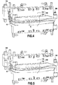
- This tool is composed of two elements main independent, namely a blade support 100 and a leading edge reinforcement support 200.
- the blade support 100 comprises an upper half-shell 102 ( figures 2 and 3 ) and a lower half-shell 104 (visible on the Figures 4 and 5 in particular) which are two independent elements coming to be fixed one on the other.
- the upper half-shell 102 has an imprint 106 of shape complementary to that of the upper surface 4a of the blade.
- the lower half-shell 104 also has an imprint (not shown in the figures) having a shape complementary to that of the lower surface of the blade.
- the half-shells 102, 104 of the blade support 100 are configured so that, when the blade 2 is positioned between them as illustrated in the Figures 4 and 5 , only the lower and upper surfaces of the leading edge 6 of the blade remain clear of any influence. The extent of these surfaces corresponds to the area on which the metal reinforcement must be fixed.
- the half-shells 102, 104 of the blade support 100 can be assembled one on the other for example by means of screw / nut type systems 108 whose tightening makes it possible to clamp the blade 2 positioned between the half-shells.
- the support for reinforcing the leading edge 200 of the tooling comprises a base 202 forming the bottom, two lateral walls 204 fixed to the bottom 202 for example by means of screws 206, and two lateral shims 208 positioned at the inside the space delimited by the bottom 202 and the side walls 204.
- the two lateral wedges 208 are spaced laterally from one another by a space 210 whose general geometry corresponds substantially to the profile of the metal reinforcement of the leading edge of the blade to be used.
- the two lateral wedges 208 are able to be able to approach and move laterally apart from one another.
- the lateral displacement of the wedges 208 is carried out by means of springs 212 exerting a push on each lateral wedge to bring it closer to the other lateral wedge, these springs being held in the retracted position by retaining screws 214 for all of the phases of use outside that of pressurization.
- These springs 212 are calibrated and positioned according to the chosen level of pressure applied to the metal reinforcement positioned between the shims.
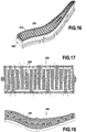
- the lateral wedges 208 are also each provided with a suction grid (or network) 216 which is positioned at their lateral face delimiting the space 210 for receiving the metallic reinforcement. These suction grids 216 are each connected to a suction circuit (not shown) opening out to the outside of the tool.
- a peripheral seal 218 can be positioned around the suction grid 216.
- leading edge reinforcement support 200 also includes heating elements 220 intended to allow a polymerization of a film of adhesive applied to the leading edge of the blade when the latter is positioned in the reinforcement. metallic.
- these heating elements 220 are arranged inside the bottom 202 of the leading edge reinforcement support ( figure 17 which shows the bottom in sectional view) and within each lateral wedge 208 ( figure 18 which is a view in longitudinal section of a lateral wedge).
- these heating elements are in the form of a circulation circuit for a heat transfer fluid 220.
- a circuit resistive electric or induction heating circuit for example a circuit resistive electric or induction heating circuit.
- the leading edge reinforcement support 200 also includes a spout flange of the metal reinforcement 222 which is interposed between the bottom 202 and one of the lateral shims 208.
- This flange 222 has the function of ensuring a clamping in reference d 'a metal reinforcement spout when this is positioned in the leading edge reinforcement support.
- the blade 2 is positioned on the upper half-shell 102 of the blade support 100 by placing the upper surface 4a thereof on the imprint 106 of this half - upper surface shell ( figures 2 and 3 ).
- the next step consists in mounting the lower half-shell 104 on the blade by positioning the imprint of this half-shell on the lower surface 4b of the blade ( figure 4 ).
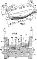
- a chock 110 of the blade root is then placed against the blade blade 10 ( figure 5 ) and the clamping of the blade in the blade support 100 is ensured by tightening systems of the screw / nut type 108. This tightening force is controlled by the use of a torque wrench.
- the next step in the process consists in clamping the trailing edge 8 of the blade.
- the blade support 100 comprises several wedges for clamping the trailing edge 112 which are inserted between the trailing edge of the blade and the lower half-shell 104 ( Figures 6 and 7 ).
- the clamping of the trailing edge of the blade ensures that the blade is held in place in the blade support in the event of its thickness being too small.
- the use of several wedges for clamping the trailing edge 112 makes it possible to guarantee contact with the edge of the trailing edge of the blade at several points whatever the profile defects thereof.
- the blade 2 is positioned and perfectly clamped in the blade support 100 of the tool while leaving the surfaces of the leading edge of the blade completely free.
- the metal reinforcement 300 intended to be fixed on the leading edge 6 of the blade is positioned in the leading edge reinforcement support 200 of the tool.
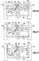
- the lateral shims 208 of the leading edge reinforcement support are spaced from one another (here manually) to allow the positioning of the metal reinforcement 300 between them in the space 210.
- the flange of beak of the metal reinforcement 222 makes it possible at this stage to ensure a reference clamping of a beak 302 of the metal reinforcement 300 between the shims.
- the shims 208 are brought together manually one from the other so that their respective lateral faces come into contact with the wings 304 (or lateral faces) of the metal reinforcement and the suction grids of these shims are put into operation to ensure a gripping by suction of the wings 304 metal reinforcement ( figure 11 ).
- Additional shims 224 are then placed on the leading edge reinforcement support between the side walls 204 and the shims 208 ( figure 12 ). These additional shims make it possible to limit the spacing of said shims 208 of the leading edge reinforcement support during the next step of opening the wings of the metal reinforcement and to control the stroke of the pressurizing springs 212 and therefore the effort they generate.
- the wings 304 of the metal reinforcement 300 being maintained in contact with the lateral faces of the shims 208 by suction, the spacing of the shims 208 from one another during the next step causes said wings 304 of the metal reinforcement to open. to allow insertion of the leading edge of the blade ( Figures 13 and 14 ). To overcome the resistance of the wings of the metal reinforcement, this spacing is achieved by means of shim opening screws (not shown in the figures) which are accessible from the side walls 204 of the leading edge reinforcement support.
- a film glue can be applied to the leading edge of the blade.
- a paste adhesive can be applied to the bottom of the cavity of the metal reinforcement, the kinematics of the tool during assembly allowing the adhesive to creep over all of the surfaces of the leading edge to be bonded.
- a liquid glue can be injected once the metal reinforcement is in place on the leading edge of the blade.
- the positioning of the leading edge 6 of the blade 2 between the wings 304 of the metal reinforcement 300 is obtained by mounting the blade support 100 on the leading edge reinforcement support 200 ( figure 15 ). Given the twisting of the leading edge of the blade, this assembly requires a combined movement of translation and rotation.
- Clamping screws 114 then allow clamping between the blade support 100 and the leading edge reinforcement support 200, as well as pressurization under the spout 302 of the metal reinforcement 300. In this way, the film glue is compacted at the top of the metal reinforcement to the final dimension.
- the next step consists in bringing the shims 208 closer to the leading edge reinforcement support (by unscrewing the shim opening screws then unscrewing the screws 214 for holding the springs 212 ) to ensure pressurization of the wings 304 of the metal reinforcement.
- This pressurization can be adjusted as required by the number of springs 212, their stiffness and the level of compression chosen.
- each wedge 208 has a shoulder 226 forming an end-of-travel stop which comes to bear against the blade or the blade support when the wedges 20 are brought together.
- the bottom 202 of the leading edge reinforcement support also includes two shoulders 228 forming an end-of-travel stop against which the wedges 208 bear when they are brought together.
- the heating elements 220 of the leading edge reinforcement support 200 are put into operation (before or after the step of pressurizing the wings of the metal reinforcement) to trigger a polymerization cycle of the adhesive film (mounting, bearing, and temperature drop).
- the blade the leading edge of which is coated with the metal reinforcement, can be released from the tool.
- the shims of the leading edge reinforcement support are again separated from one another, the nozzle flange is released and the blade support is removed from the leading edge reinforcement support. Finally, the blade is released from the blade support by disassembling the two half-shells thereof.
Landscapes
- Engineering & Computer Science (AREA)
- Mechanical Engineering (AREA)
- General Engineering & Computer Science (AREA)
- Chemical & Material Sciences (AREA)
- Materials Engineering (AREA)
- Composite Materials (AREA)
- Architecture (AREA)
- Structures Of Non-Positive Displacement Pumps (AREA)
- Turbine Rotor Nozzle Sealing (AREA)
Description
- La présente invention se rapporte au domaine général des aubes de turbomachine munies d'un renfort métallique sur leur bord d'attaque. Elle vise plus particulièrement un outillage et un procédé pour la fixation d'un renfort métallique sur le bord d'attaque d'une aube de turbomachine en matériau composite.
- Il est connu d'équiper les aubes de soufflante d'une turbomachine qui sont réalisées en matériau composite d'un renfort structurel métallique s'étendant sur toute la hauteur de l'aube. Un tel renfort permet de protéger l'aubage composite lors de l'impact sur la soufflante d'un corps étranger tel qu'un oiseau ingéré par la turbomachine par exemple.
- Un procédé connu pour fixer le renfort métallique sur le bord d'attaque de l'aube en matériau composite est le suivant. L'aube est maintenue dans un support un repère de positionnement en envergure du bord d'attaque de l'aube est mis en place. Un film de colle est ensuite appliqué sur les surfaces du bord d'attaque de l'aube et le renfort métallique est pré-positionné manuellement sur le bord d'attaque de l'aube. La colle est alors polymérisée en autoclave.
- Un tel procédé présente de nombreux inconvénients. Il s'agit notamment d'un procédé manuel qui dépend d'un opérateur, ce qui présente un risque élevé de variabilité de la santé matière du collage et de variabilité de positionnement relatif des pièces assemblées. Ces risques doivent être compensés par une gamme de contrôle très sévère. Il en résulte un coût de production élevé.
- Le document
US 5430937 divulgue la fabrication d'une pale de rotor d'hélicoptère en matériau composite. Le documentEP 1777063 divulgue un procédé de fabrication d'une aube de turbomachine composite. - La présente invention a donc pour but principal de proposer un outillage et un procédé de fixation d'un bord qui ne présentent pas les inconvénients précités.
- Conformément à l'invention, ce but est atteint grâce à un outillage pour la fixation d'un renfort métallique sur le bord d'attaque d'une aube de turbomachine comprenant un support d'aube destiné à recevoir une aube tout en laissant des surfaces du bord d'attaque de l'aube dégagées, et un support de renfort de bord d'attaque sur lequel est destiné à être monté le support d'aube et comprenant deux cales latérales entre lesquelles le renfort métallique du bord d'attaque de l'aube est destiné à être positionné, les cales étant aptes à pouvoir se rapprocher et s'écarter l'une de l'autre et étant munies chacune d'une grille d'aspiration destinée à assurer une préhension du renfort métallique, le support de renfort de bord d'attaque comprenant en outre des éléments chauffant destinés à permettre une polymérisation d'un film de colle appliqué sur des surfaces du bord d'attaque de l'aube lorsque celui-ci est positionné sur le renfort métallique et des épaulements formant des butées conformées pour venir en appui contre l'aube, le support d'aube ou les cales lors du rapprochement des cales.
- Un tel outillage permet d'éviter les défauts de positionnements relatifs entre l'aube et le renfort métallique et d'assurer ainsi la maîtrise et la reproductibilité du positionnement du renfort métallique sur le bord d'attaque de l'aube. En particulier, l'épaisseur de colle peut être maîtrisée. La présence au niveau du support de renfort de bord d'attaque de cales pouvant s'écarter l'une de l'autre permet d'ouvrir les ailes du renfort lors de la mise en place du bord d'attaque de l'aube, ce qui facilite cette opération. Ainsi, le montage en force du renfort sur le bord d'attaque de l'aube peut être évité, ce qui garantit l'intégrité pour l'aube et pour le film de colle. De plus, la polymérisation de la colle est réalisée hors autoclave grâce aux éléments chauffant de l'outillage, ce qui permet d'augmenter la productivité et de diminuer la fatigue thermique de l'aube. En outre, la température au cours de l'ensemble du cycle de polymérisation (montée, palier, descente) peut être aisément contrôlée.
- De préférence, le support d'aube comprend une demi-coquille extrados ayant une empreinte de forme complémentaire à celle d'une surface extrados de l'aube, une demi-coquille intrados ayant une empreinte de forme complémentaire à celle d'une surface intrados de l'aube, et moyens d'application d'un effort de serrage entre la demi-coquille intrados et la demi-coquille extrados.
- De préférence également, le support d'aube comprend en outre des cales de bridage d'un bord de fuite de l'aube. Ce bridage complémentaire garantit le maintien en place de l'aube en cas d'épaisseur trop faible de l'aube. De plus, l'utilisation de plusieurs cales de bridage permet de garantir un contact avec l'arête du bord de fuite de l'aube en plusieurs points quelque soient les défauts de profil de celui-ci.
- De préférence encore, le support de renfort de bord d'attaque comprend en outre des butées de fin course des cales. La présence de ces butées de fin de course permet de limiter la course des cales du support de renfort de bord d'attaque notamment lors de l'application de la pression sur les ailes du renfort métallique. Ainsi, il est possible de garantir la géométrie du renfort métallique et de limiter l'écrasement du film de colle (ce qui garantit le respect de l'épaisseur de colle minimale requise). De plus, il est possible d'assurer la continuité aérodynamique entre le renfort métallique et l'aube en cas d'aube légèrement trop épaisse.
- Le support de renfort de bord d'attaque peut comprendre des moyens pour rapprocher ou écarter les cales l'une de l'autre.
- De même, les éléments chauffant du support de renfort de bord d'attaque peuvent comprendre un circuit de circulation d'un fluide caloporteur.
- L'invention a également pour objet un procédé de fixation d'un renfort métallique sur le bord d'attaque d'une aube de turbomachine au moyen d'un outillage tel que défini précédemment, le procédé comprenant une étape de positionnement et de bridage de l'aube dans le support d'aube de l'outillage en laissant les surfaces du bord d'attaque de l'aube dégagées, une étape d'application de colle sur les surfaces dégagées du bord d'attaque de l'aube, une étape de positionnement et de préhension du renfort métallique dans le support de renfort de bord d'attaque de l'outillage, une étape de positionnement du renfort métallique sur le bord d'attaque de l'aube en montant le support d'aube sur le support de renfort de bord d'attaque, une étape d'application d'une pression sur des ailes du renfort métallique, et une étape de polymérisation de la colle appliquée sur les surfaces dégagés sur le bord d'attaque de l'aube par les éléments chauffant du support de renfort de bord d'attaque de l'outillage.
- Un tel procédé présente l'avantage de pouvoir être automatisé sans nécessiter d'interventions complexes d'un opérateur. De plus, il permet d'assurer la maîtrise et la reproductibilité du positionnement du renfort métallique sur le bord d'attaque de l'aube.
- De préférence, l'étape de positionnement et de bridage de l'aube dans le support d'aube comprend en outre le bridage d'un bord de fuite de l'aube.
- L'étape de positionnement et de préhension du renfort métallique dans le support de renfort de bord d'attaque peut comprendre successivement l'écartement l'une de l'autre des cales latérales du support de renfort de bord d'attaque, le positionnement du renfort métallique entre les cales du support de renfort de bord d'attaque, le bridage d'un bec du renfort métallique entre les cales, et l'aspiration des ailes du renfort métallique pour assurer leur préhension.
- Postérieurement à l'étape de positionnement et de préhension du renfort métallique dans le support de renfort de bord d'attaque et préalablement à l'étape de positionnement du renfort métallique sur le bord d'attaque de l'aube, le procédé peut comprendre en outre une étape d'écartement l'une de l'autre des cales latérales du support de renfort de bord d'attaque pour ouvrir les ailes du renfort métallique.
- Préalablement à l'étape d'écartement l'une de l'autre des cales latérales du support de renfort de bord d'attaque, des cales supplémentaires peuvent être assemblées sur le support de renfort de bord d'attaque pour limiter l'écartement desdites cales latérales.
- L'aube peut être réalisée en matériau composite à fibres de carbone et le renfort métallique peut être réalisé à base de titane.
- L'invention a encore pour objet une application du procédé tel que défini précédemment à la fixation d'un renfort métallique sur le bord d'attaque d'une aube de soufflante de turboréacteur.
- D'autres caractéristiques et avantages de la présente invention ressortiront de la description faite ci-dessous, en référence aux dessins annexés qui en illustrent un exemple de réalisation dépourvu de tout caractère limitatif. Sur les figures :
- la
figure 1 est une vue schématique d'une aube de soufflante de turboréacteur munie d'un renfort métallique sur son bord d'attaque ; - les
figures 2 à 15 illustrent différentes étapes du procédé de fixation d'un renfort métallique sur le bord d'attaque d'une aube au moyen d'un outillage selon l'invention ; - la
figure 16 représente en vue de côté une cale latérale du support de renfort de bord d'attaque de l'outillage selon l'invention montrant sa grille d'aspiration ; - la
figure 17 est une vue en coupe du fond du support de renfort de bord d'attaque de l'outillage selon l'invention montrant ses éléments chauffant ; et - la
figure 18 est une vue en coupe longitudinale d'une cale latérale du support de renfort de bord d'attaque de l'outillage selon l'invention montrant ses éléments chauffant. - L'invention s'applique à la fixation d'un renfort métallique sur le bord d'attaque de toute aube de turbomachine. Elle trouve une application privilégiée dans la fixation d'un renfort réalisé en titane sur le bord d'attaque d'une aube de soufflante de turboréacteur réalisée en matériau composite à fibres de carbone telle que celle illustrée sur la
figure 1 . - De façon connue en soi, une aube 2 de soufflante de turboréacteur réalisée en matériau composite comprend une pale aérodynamique 4 ayant une surface extrados 4a et une surface intrados 4b. Les surfaces intrados et extrados s'étendent entre un bord d'attaque 6 et un bord de fuite 8. L'aube est en outre munie d'un pied 10 destiné à être monté sur un disque de rotor.
- L'aube 2 en matériau composite est obtenue par drapage ou tissage d'un matériau composite. A titre d'exemple, ce matériau composite peut être un assemblage de fibres de carbone tissées et moulées par un procédé d'injection sous vide RTM (pour « Resin Transfer Molding »).
- L'aube 2 comporte en outre un renfort structurel métallique 300 qui est collé sur bord d'attaque 6 en s'étendant entre le pied 10 et le sommet 12 de l'aube.
- Pour fixer le renfort métallique sur le bord d'attaque 6 d'une telle aube, il est prévu, conformément à l'invention, de recourir à un outillage spécifique. Cet outillage est composé de deux éléments principaux indépendants, à savoir un support d'aube 100 et un support de renfort de bord d'attaque 200.
- Comme représenté par la
figure 2 , le support d'aube 100 comprend une demi-coquille extrados 102 (figures 2 et 3 ) et une demi-coquille intrados 104 (visible sur lesfigures 4 et 5 notamment) qui sont deux éléments indépendants venant se fixer l'un sur l'autre. - La demi-coquille extrados 102 présente une empreinte 106 de forme complémentaire à celle de la surface extrados 4a de l'aube. De même, la demi-coquille intrados 104 comporte également une empreinte (non représentée sur les figures) ayant une forme complémentaire à celle de la surface intrados de l'aube.
- Les demi-coquilles 102, 104 du support d'aube 100 sont configurées de sorte que, lorsque l'aube 2 est positionnée entre celles-ci comme illustré sur les
figures 4 et 5 , seules les surfaces intrados et extrados du bord d'attaque 6 de l'aube restent dégagées de toute emprise. L'étendue de ces surfaces correspond à la zone sur laquelle le renfort métallique doit être fixé. - Les demi-coquilles 102, 104 du support d'aube 100 peuvent être assemblées l'une sur l'autre par exemple par l'intermédiaire de systèmes de type vis/écrous 108 dont le serrage permet d'assurer un bridage de l'aube 2 positionnée entre les demi-coquilles.
- Comme représenté sur les
figures 9 à 14 , le support de renfort de bord d'attaque 200 de l'outillage comprend une base 202 formant fond, deux parois latérales 204 fixées sur le fond 202 par exemple par l'intermédiaire de vis 206, et deux cales latérales 208 positionnées à l'intérieur de l'espace délimité par le fond 202 et les parois latérales 204. - De façon plus précise, les deux cales latérales 208 sont espacées latéralement l'une de l'autre par un espace 210 dont la géométrie générale correspond sensiblement au profil du renfort métallique du bord d'attaque de l'aube à utiliser.
- De plus, les deux cales latérales 208 sont aptes à pouvoir se rapprocher et s'écarter latéralement l'une de l'autre. Dans l'exemple illustré sur la
figure 9 , le déplacement latéral des cales 208 est réalisé au moyen de ressorts 212 exerçant une poussée sur chaque cale latérale pour la rapprocher de l'autre cale latérale, ces ressorts étant maintenus en position rétractée par des vis de maintien 214 pour l'ensemble des phases d'utilisation hors de celle de mise en pression. Ces ressorts 212 sont tarés et positionnés en fonction du niveau choisi de pression appliquée sur le renfort métallique positionné entre les cales. - Bien entendu, d'autres moyens pour permettre aux cales latérales de se rapprocher et s'écarter l'une de l'autre peuvent être envisagés. On pourra par exemple utiliser des vessies gonflables ou des vérins hydrauliques venant exercer une pression latérale sur ces cales pour les déplacer.
- Les cales latérales 208 sont également munies chacune d'une grille (ou réseau) d'aspiration 216 qui est positionnée au niveau de leur face latérale délimitant l'espace 210 de réception du renfort métallique. Ces grilles d'aspiration 216 sont chacune reliées à un circuit d'aspiration (non représenté) débouchant à l'extérieur de l'outillage. Come représenté sur la
figure 16 qui montre une cale latérale 208 de côté, un joint périphérique 218 peut être positionné autour de la grille d'aspiration 216. - Par ailleurs, le support de renfort de bord d'attaque 200 comprend encore des éléments chauffant 220 destinés à permettre une polymérisation d'un film de colle appliqué sur le bord d'attaque de l'aube lorsque celui-ci est positionné dans le renfort métallique.
- Plus précisément, comme représenté sur les
figures 17 et 18 , ces éléments chauffant 220 sont disposés à l'intérieur du fond 202 du support de renfort de bord d'attaque (figure 17 qui montre le fond en vue de coupe) et au sein de chaque cale latérale 208 (figure 18 qui est une vue en coupe longitudinale d'une cale latérale). Dans l'exemple représenté sur ces figures, ces éléments chauffant se présentent sous la forme d'un circuit de circulation d'un fluide caloporteur 220. Bien entendu, il est possible d'envisager d'autres types éléments chauffant, par exemple un circuit électrique résistif ou un circuit de chauffage par induction. - Le support de renfort de bord d'attaque 200 comprend encore une bride de bec du renfort métallique 222 qui est interposée entre le fond 202 et l'une des cales latérales 208. Cette bride 222 a pour fonction d'assurer un bridage en références d'un bec du renfort métallique lorsque celui-ci est positionné dans le support de renfort de bord d'attaque.
- Le procédé de fixation d'un renfort métallique sur le bord d'attaque d'une aube au moyen de l'outillage précédemment décrit découle de ce qui précède.
- Au cours d'une première étape de ce procédé de fixation, l'aube 2 est positionnée sur la demi-coquille extrados 102 du support d'aube 100 en plaçant la face extrados 4a de celle-ci sur l'empreinte 106 de cette demi-coquille extrados (
figures 2 et 3 ). - L'étape suivante consiste à monter la demi-coquille intrados 104 sur l'aube en positionnant l'empreinte de cette demi-coquille sur la surface intrados 4b de l'aube (
figure 4 ). - Une cale de serrage 110 du pied de l'aube est ensuite mise en place contre le pied 10 de l'aube (
figure 5 ) et le bridage de l'aube dans le support d'aube 100 est assuré par serrage des systèmes de type vis/écrous 108. Cet effort de serrage est maîtrisé par l'utilisation d'une clé dynamométrique. - L'étape suivante du procédé consiste à réaliser un bridage du bord de fuite 8 de l'aube. A cet effet, le support d'aube 100 comprend plusieurs cales de bridage du bord de fuite 112 qui viennent s'insérer entre le bord de fuite de l'aube et la demi-coquille intrados 104 (
figures 6 et 7 ). - Le bridage du bord de fuite de l'aube garantit le maintien en place de l'aube dans le support d'aube en cas d'épaisseur trop faible de celle-ci. De plus, l'utilisation de plusieurs cales de bridage du bord de fuite 112 permet de garantir un contact avec l'arête du bord de fuite de l'aube en plusieurs points quelque soient les défauts de profil de celui-ci.
- Ainsi, l'aube 2 est positionnée et parfaitement bridée dans le support d'aube 100 de l'outillage tout en laissant les surfaces du bord d'attaque de l'aube totalement dégagées.
- Au cours de l'étape suivante, le renfort métallique 300 destiné à venir se fixer sur le bord d'attaque 6 de l'aube est positionné dans le support de renfort de bord d'attaque 200 de l'outillage.
- A cet effet, comme représenté sur la
figure 10 , les cales latérales 208 du support de renfort de bord d'attaque sont écartées l'une de l'autre (ici de façon manuelle) pour permettre le positionnement du renfort métallique 300 entre celles-ci dans l'espace 210. La bride de bec du renfort métallique 222 permet à ce stade d'assurer un bridage en références d'un bec 302 du renfort métallique 300 entre les cales. - Une fois le renfort métallique positionné sur le support de renfort de bord d'attaque, les cales 208 sont rapprochées manuellement l'une de l'autre pour que leurs faces latérales respectives viennent en contact avec les ailes 304 (ou faces latérales) du renfort métallique et les grilles d'aspiration de ces cales sont mises en fonctionnement pour assurer une préhension par aspiration des ailes 304 du renfort métallique (
figure 11 ). - Des cales supplémentaires 224 sont ensuite disposées sur le support de renfort de bord d'attaque entre les parois latérales 204 et les cales 208 (
figure 12 ). Ces cales supplémentaires permettent de limiter l'écartement desdites cales 208 du support de renfort de bord d'attaque au cours de l'étape suivante d'ouverture des ailes du renfort métallique et de maîtriser la course des ressorts 212 de mise en pression et donc l'effort qu'ils génèrent. - Les ailes 304 du renfort métallique 300 étant maintenues en contact avec les faces latérales des cales 208 par aspiration, l'écartement des cales 208 l'une de l'autre au cours de l'étape suivante entraîne une ouverture desdites ailes 304 du renfort métallique pour permettre l'insertion du bord d'attaque de l'aube (
figures 13 et 14 ). Pour vaincre la résistance des ailes du renfort métallique, cet écartement est réalisé au moyen de vis d'ouverture de cales (non représentées sur les figures) qui sont accessibles depuis les parois latérales 204 du support de renfort de bord d'attaque. - Préalablement au positionnement du bord d'attaque 6 de l'aube 2 entre les ailes 304 du renfort métallique 300, il est nécessaire d'appliquer de la colle 14 sur les surfaces du bord d'attaque de l'aube qui ne sont pas en prises avec le support d'aube (voir la
figure 8 ). A cet effet, une colle en film peut être appliquée sur le bord d'attaque de l'aube. Alternativement, une colle en pâte peut être appliquée en fond de cavité du renfort métallique, la cinématique de l'outillage lors de l'assemblage permettant un fluage de la colle sur l'ensemble des surfaces du bord d'attaque à coller. Encore alternativement, une colle liquide peut être injectée une fois le renfort métallique mis en place sur le bord d'attaque de l'aube. - Ensuite, le positionnement du bord d'attaque 6 de l'aube 2 entre les ailes 304 du renfort métallique 300 est obtenu en montant le support d'aube 100 sur le support de renfort de bord d'attaque 200 (
figure 15 ). Compte tenu du vrillage du bord d'attaque de l'aube, cet assemblage nécessite un mouvement combiné de translation et de rotation. - Des vis de serrage 114 permettent alors un bridage entre le support d'aube 100 et le support de renfort de bord d'attaque 200, ainsi qu'une mise en pression sous le bec 302 du renfort métallique 300. De la sorte, le film de colle est compacté en sommet du renfort métallique jusqu'à la cote finale.
- Ensuite, l'étape suivante consiste à rapprocher à nouveau l'une de l'autre les cales 208 du support de renfort de bord d'attaque (par dévissage des vis d'ouvertures de cales puis dévissage des vis 214 de maintien des ressorts 212) pour assurer une mise en pression des ailes 304 du renfort métallique. Cette mise en pression peut être ajustée en fonction des besoins par le nombre de ressorts 212, leur raideur et le niveau de compression choisie.
- Par ailleurs, la présence au niveau du support de renfort de bord d'attaque de butées de fin course des cales latérales de celui-ci permet de garantir une épaisseur du film de colle. Plus précisément, comme représenté notamment sur la
figure 9 , chaque cale 208 présente un épaulement 226 formant butée de fin de course qui vient en appui contre l'aube ou le support d'aube lors du rapprochement des cales 208. De plus, le fond 202 du support de renfort de bord d'attaque comprend également deux épaulements 228 formant butée de fin de course contre lesquels viennent en appui les cales 208 lors de leur rapprochement. - Au cours de cette étape d'application d'une pression sur des ailes du renfort métallique, la préhension de ces ailes par aspiration est maintenue pour garantir le positionnement du renfort métallique en cas de défaut de fermeture des ailes de celui-ci.
- Les éléments chauffant 220 du support de renfort de bord d'attaque 200 sont mis en fonctionnement (avant ou après l'étape de mise en pression des ailes du renfort métallique) pour déclencher un cycle de polymérisation du film de colle (montée, palier, et descente de température).
- Une fois la colle polymérisée et l'ensemble refroidi, l'aube dont le bord d'attaque est revêtu du renfort métallique peut être libérée de l'outillage. A cet effet, les cales du support de renfort de bord d'attaque sont à nouveau écartées l'une de l'autre, la bride de bec est libérée et le support d'aube est démontée du support de renfort de bord d'attaque. Enfin, l'aube est libérée du support d'aube en désassemblant les deux demi-coquilles de celui-ci.
Claims (12)
- Outillage pour la fixation d'un renfort métallique (300) sur le bord d'attaque (6) d'une aube (2) de turbomachine comprenant :un support d'aube (100) destiné à recevoir une aube tout en laissant des surfaces du bord d'attaque de l'aube dégagées ; etun support de renfort de bord d'attaque (200) sur lequel est destiné à être monté le support d'aube et comprenant deux cales latérales (208) entre lesquelles le renfort métallique du bord d'attaque de l'aube est destiné à être positionné, les cales étant aptes à pouvoir se rapprocher et s'écarter l'une de l'autre et étant munies chacune d'une grille d'aspiration (216) destinée à assurer une préhension du renfort métallique, le support de renfort de bord d'attaque comprenant en outre des éléments chauffant (220) destinés à permettre une polymérisation d'un film de colle (14) appliqué sur des surfaces du bord d'attaque de l'aube lorsque celui-ci est positionné sur le renfort métallique et des épaulements formant des butées (226, 228) conformés pour venir en appui contre l'aube, le support d'aube ou les cales lors du rapprochement des cales (208).
- Outillage selon la revendication 1, dans lequel le support d'aube (100) comprend une demi-coquille extrados (102) ayant une empreinte (106) de forme complémentaire à celle d'une surface extrados de l'aube, une demi-coquille intrados (104) ayant une empreinte de forme complémentaire à celle d'une surface intrados de l'aube, et moyens (108) d'application d'un effort de serrage entre la demi-coquille intrados et la demi-coquille extrados.
- Outillage selon l'une des revendications 1 et 2, dans lequel le support d'aube comprend en outre des cales (112) de bridage d'un bord de fuite (8) de l'aube (2).
- Outillage selon l'une quelconque des revendications 1 à 3, dans lequel le support de renfort de bord d'attaque (200) comprend des moyens pour rapprocher ou écarter les cales l'une de l'autre.
- Outillage selon l'une quelconque des revendications 1 à 4, dans lequel les éléments chauffant du support de renfort de bord d'attaque (200) comprennent un circuit de circulation d'un fluide caloporteur (220).
- Procédé de fixation d'un renfort métallique sur le bord d'attaque d'une aube de turbomachine au moyen d'un outillage selon l'une quelconque des revendications 1 à 5, comprenant :une étape de positionnement et de bridage de l'aube (2) dans le support d'aube (100) de l'outillage en laissant les surfaces du bord d'attaque (6) de l'aube dégagées ;une étape d'application de colle (14) sur les surfaces dégagées du bord d'attaque de l'aube ;une étape de positionnement et de préhension du renfort métallique (300) dans le support de renfort de bord d'attaque (200) de l'outillage ;une étape de positionnement du renfort métallique sur le bord d'attaque de l'aube en montant le support d'aube sur le support de renfort de bord d'attaque ;une étape d'application d'une pression sur des ailes (304) du renfort métallique ; etune étape de polymérisation de la colle appliquée sur les surfaces dégagés sur le bord d'attaque de l'aube par les éléments chauffant (220) du support de renfort de bord d'attaque de l'outillage.
- Procédé selon la revendication 6, dans lequel l'étape de positionnement et de bridage de l'aube dans le support d'aube comprend en outre le bridage d'un bord de fuite (8) de l'aube (2).
- Procédé selon l'une des revendications 6 et 7, dans lequel l'étape de positionnement et de préhension du renfort métallique dans le support de renfort de bord d'attaque comprend successivement l'écartement l'une de l'autre des cales latérales (208) du support de renfort de bord d'attaque, le positionnement du renfort métallique entre les cales du support de renfort de bord d'attaque, le bridage d'un bec (302) du renfort métallique entre les cales, et l'aspiration des ailes (304) du renfort métallique pour assurer leur préhension.
- Procédé selon l'une quelconque des revendications 6 à 8, comprenant en outre, postérieurement à l'étape de positionnement et de préhension du renfort métallique dans le support de renfort de bord d'attaque et préalablement à l'étape de positionnement du renfort métallique sur le bord d'attaque de l'aube, une étape d'écartement l'une de l'autre des cales latérales du support de renfort de bord d'attaque pour ouvrir les ailes du renfort métallique.
- Procédé selon la revendication 9, dans lequel, préalablement à l'étape d'écartement l'une de l'autre des cales latérales (208) du support de renfort de bord d'attaque, des cales supplémentaires (224) sont assemblées sur le support de renfort de bord d'attaque pour limiter l'écartement desdites cales latérales.
- Procédé selon l'une quelconque des revendications 6 à 10, dans lequel l'aube (2) est réalisée en matériau composite à fibres de carbone et le renfort métallique (300) est réalisé à base de titane.
- Application du procédé selon l'une quelconque des revendications 6 à 11 à la fixation d'un renfort métallique sur le bord d'attaque d'une aube de soufflante de turboréacteur.
Applications Claiming Priority (2)
| Application Number | Priority Date | Filing Date | Title |
|---|---|---|---|
| FR1354147A FR3005280B1 (fr) | 2013-05-06 | 2013-05-06 | Outillage pour la fixation d'un renfort metallique sur le bord d'attaque d'une aube de turbomachine et procede utilisant un tel outillage |
| PCT/FR2014/051012 WO2014181055A1 (fr) | 2013-05-06 | 2014-04-28 | Outillage pour la fixation d'un renfort métallique sur le bord d'attaque d'une aube de turbomachine et procédé utilisant un tel outillage |
Publications (2)
| Publication Number | Publication Date |
|---|---|
| EP2994293A1 EP2994293A1 (fr) | 2016-03-16 |
| EP2994293B1 true EP2994293B1 (fr) | 2020-04-15 |
Family
ID=49209483
Family Applications (1)
| Application Number | Title | Priority Date | Filing Date |
|---|---|---|---|
| EP14726703.3A Active EP2994293B1 (fr) | 2013-05-06 | 2014-04-28 | Outillage pour la fixation d'un renfort métallique sur le bord d'attaque d'une aube de turbomachine et procédé utilisant un tel outillage |
Country Status (8)
| Country | Link |
|---|---|
| US (1) | US10180070B2 (fr) |
| EP (1) | EP2994293B1 (fr) |
| CN (1) | CN105189090B (fr) |
| BR (1) | BR112015028073B1 (fr) |
| CA (1) | CA2911310C (fr) |
| FR (1) | FR3005280B1 (fr) |
| RU (1) | RU2665198C2 (fr) |
| WO (1) | WO2014181055A1 (fr) |
Families Citing this family (13)
| Publication number | Priority date | Publication date | Assignee | Title |
|---|---|---|---|---|
| US11346362B2 (en) | 2017-07-25 | 2022-05-31 | Raytheon Technologies Corporation | Processes and tooling associated with diffusion bonding |
| JP6875238B2 (ja) * | 2017-09-15 | 2021-05-19 | 三菱パワー株式会社 | 貼付治具及び動翼の製造方法 |
| CN112672836A (zh) * | 2018-03-21 | 2021-04-16 | 泰普爱复合材料股份有限公司 | 带有导热凸缘的模具 |
| FR3079445B1 (fr) * | 2018-03-28 | 2020-04-24 | Safran | Procede de fabrication d'une aube en materiau composite a bord d'attaque metallique rapporte pour turbine a gaz |
| FR3093132B1 (fr) * | 2019-02-27 | 2021-02-12 | Safran Aircraft Engines | Assemblage d’une aube directrice de sortie pour turbomachine d’aéronef à l’aide d’une vessie gonflable |
| FR3102378B1 (fr) * | 2019-10-23 | 2021-11-12 | Safran Aircraft Engines | Procédé de fabrication d’une aube en matériau composite avec bord d’attaque métallique rapporté |
| GB202002429D0 (en) * | 2020-02-21 | 2020-04-08 | Rolls Royce Plc | A fixing apparatus |
| CN112360855B (zh) * | 2020-10-22 | 2022-08-09 | 中航复合材料有限责任公司 | 一种复合材料风扇叶片金属增强件胶接定位装置及方法 |
| CN112355948B (zh) * | 2020-10-29 | 2022-08-26 | 中国航发南方工业有限公司 | 导向叶片组装防护夹具 |
| US20220347949A1 (en) * | 2021-04-28 | 2022-11-03 | Safran Aircraft Engines | Device for shaping a fibrous preform for producing a bladed part of a turbomachine |
| CN116690135A (zh) * | 2022-02-28 | 2023-09-05 | 富联裕展科技(深圳)有限公司 | 组装设备和组装方法 |
| CN114714119B (zh) * | 2022-05-05 | 2023-06-23 | 中国航发航空科技股份有限公司 | 一种中介机匣支板的夹持装置 |
| FR3141721A1 (fr) * | 2022-11-09 | 2024-05-10 | Safran | Support d’encollage de renfort et procédé d’encollage de renfort à l’aide d’un tel support d’encollage |
Family Cites Families (10)
| Publication number | Priority date | Publication date | Assignee | Title |
|---|---|---|---|---|
| US5430937A (en) * | 1994-07-15 | 1995-07-11 | United Technologies Corporation | Apparatus and methods for fabricating a helicopter main rotor blade |
| US5836062A (en) * | 1997-04-16 | 1998-11-17 | Sikorsky Aircraft Corporation | Apparatus for assembling a helicopter main rotor blade subassembly |
| FR2892339B1 (fr) * | 2005-10-21 | 2009-08-21 | Snecma Sa | Procede de fabrication d'une aube de turbomachine composite, et aube obtenue par ce procede |
| FR2918919B1 (fr) * | 2007-07-17 | 2013-03-29 | Eurocopter France | Procede et dispositif pour coller la coiffe metallique d'un bord d'attaque d'une voiture |
| US7805839B2 (en) * | 2007-12-31 | 2010-10-05 | Turbine Engine Components Technologies Corporation | Method of manufacturing a turbine fan blade |
| CN102123849B (zh) * | 2008-06-20 | 2015-03-11 | 维斯塔斯风力系统有限公司 | 由具有横向于中间部分延伸的端部的元件制造用于风轮机的翼梁的方法 |
| US20100269979A1 (en) * | 2009-04-27 | 2010-10-28 | Spirit Aerosystems, Inc. | Bladder pressure bonding apparatus |
| EP2998062A1 (fr) * | 2009-11-30 | 2016-03-23 | Snecma | Procédé de réalisation d'un renfort métallique d'aube de turbomachine |
| FR2954200B1 (fr) * | 2009-12-23 | 2012-03-02 | Snecma | Procede de realisation d'un renfort metallique d'aube de turbomachine |
| US20110194941A1 (en) * | 2010-02-05 | 2011-08-11 | United Technologies Corporation | Co-cured sheath for composite blade |
-
2013
- 2013-05-06 FR FR1354147A patent/FR3005280B1/fr active Active
-
2014
- 2014-04-28 EP EP14726703.3A patent/EP2994293B1/fr active Active
- 2014-04-28 BR BR112015028073-0A patent/BR112015028073B1/pt active IP Right Grant
- 2014-04-28 WO PCT/FR2014/051012 patent/WO2014181055A1/fr active Application Filing
- 2014-04-28 CN CN201480025711.2A patent/CN105189090B/zh active Active
- 2014-04-28 RU RU2015152148A patent/RU2665198C2/ru active
- 2014-04-28 US US14/889,710 patent/US10180070B2/en active Active
- 2014-04-28 CA CA2911310A patent/CA2911310C/fr active Active
Non-Patent Citations (1)
| Title |
|---|
| None * |
Also Published As
| Publication number | Publication date |
|---|---|
| CN105189090B (zh) | 2018-10-19 |
| BR112015028073B1 (pt) | 2020-10-20 |
| FR3005280A1 (fr) | 2014-11-07 |
| BR112015028073A2 (pt) | 2017-07-25 |
| WO2014181055A1 (fr) | 2014-11-13 |
| FR3005280B1 (fr) | 2015-05-15 |
| RU2015152148A (ru) | 2017-06-13 |
| US10180070B2 (en) | 2019-01-15 |
| CA2911310A1 (fr) | 2014-11-13 |
| US20160076387A1 (en) | 2016-03-17 |
| RU2665198C2 (ru) | 2018-08-28 |
| EP2994293A1 (fr) | 2016-03-16 |
| CA2911310C (fr) | 2021-12-21 |
| CN105189090A (zh) | 2015-12-23 |
Similar Documents
| Publication | Publication Date | Title |
|---|---|---|
| EP2994293B1 (fr) | Outillage pour la fixation d'un renfort métallique sur le bord d'attaque d'une aube de turbomachine et procédé utilisant un tel outillage | |
| EP2869985B1 (fr) | Procédé de fixation d'un renfort métallique structurel sur une partie d'une aube de turbine à gaz en matériau composite et moule d'injection pour la mise en oeuvre d'un tel procédé | |
| EP0984853B1 (fr) | Outillage de reparation sur site d'une structure composite presentant une zone endommagee et procede correspondant | |
| EP2831425B1 (fr) | Procédé de démontage d'un renfort d'une pièce | |
| EP2932051B1 (fr) | Panneaux acoustiques amovibles pour carter de turboreacteur | |
| EP2416946B1 (fr) | Procede de fabrication d'un panneau raidi en materiau composite a matrice thermoplastique et panneau ainsi obtenu | |
| CA2838922C (fr) | Procede de renforcement local d'un panneau composite a renfort fibreux et panneau obtenu par un tel procede | |
| EP2542377B1 (fr) | Support de blocage d'une aube par sa pale lors de l'usinage de son pied. | |
| FR2989607A1 (fr) | Procede de realisation d'un renfort metallique avec insert pour la protection d'un bord d'attaque en materiau composite | |
| CA2921901C (fr) | Procede de conformage a haute temperature d'un renfort metallique d'aube | |
| EP2145750B1 (fr) | Procédé de montage d'une pièce métallique dans une pièce en matériau composite | |
| EP3959068B1 (fr) | Procédé de réparation d'une aube en matériau composite | |
| EP3259083B1 (fr) | Procede de forgeage a haute temperature d'une piece metallique preformee et outillage de forme apte au forgeage | |
| FR3042779A1 (fr) | Procede de reparation d'une structure d'aeronef a partir de plaques deformables | |
| EP2950990B1 (fr) | Moule comprenant des coquilles et au moins un tiroir | |
| EP2226247B1 (fr) | Procédé d'assemblage d'un tapis dégivreur sur une pièce de voilure | |
| FR3021567A1 (fr) | Procede de realisation d'un modele perdu destine a etre utilise en fonderie | |
| FR3026539A1 (fr) | Dispositif de signalisation comportant un panneau pourvu d'un profile de fixation a un support | |
| FR3027052A1 (fr) | Procede de fabrication d'une aube creuse composite par flexion d'un capot, et aube pouvant etre fabriquee par ce procede |
Legal Events
| Date | Code | Title | Description |
|---|---|---|---|
| PUAI | Public reference made under article 153(3) epc to a published international application that has entered the european phase |
Free format text: ORIGINAL CODE: 0009012 |
|
| 17P | Request for examination filed |
Effective date: 20151112 |
|
| AK | Designated contracting states |
Kind code of ref document: A1 Designated state(s): AL AT BE BG CH CY CZ DE DK EE ES FI FR GB GR HR HU IE IS IT LI LT LU LV MC MK MT NL NO PL PT RO RS SE SI SK SM TR |
|
| AX | Request for extension of the european patent |
Extension state: BA ME |
|
| RIN1 | Information on inventor provided before grant (corrected) |
Inventor name: CHAUVIN, THIERRY Inventor name: VARIN, FRANCK, BERNARD, LEON |
|
| DAX | Request for extension of the european patent (deleted) | ||
| STAA | Information on the status of an ep patent application or granted ep patent |
Free format text: STATUS: EXAMINATION IS IN PROGRESS |
|
| 17Q | First examination report despatched |
Effective date: 20180309 |
|
| RAP1 | Party data changed (applicant data changed or rights of an application transferred) |
Owner name: SAFRAN AIRCRAFT ENGINES Owner name: SAFRAN |
|
| GRAP | Despatch of communication of intention to grant a patent |
Free format text: ORIGINAL CODE: EPIDOSNIGR1 |
|
| STAA | Information on the status of an ep patent application or granted ep patent |
Free format text: STATUS: GRANT OF PATENT IS INTENDED |
|
| RIC1 | Information provided on ipc code assigned before grant |
Ipc: F04D 29/02 20060101ALI20191030BHEP Ipc: B29L 31/08 20060101ALN20191030BHEP Ipc: F01D 5/28 20060101ALI20191030BHEP Ipc: B23Q 3/06 20060101ALN20191030BHEP Ipc: F01D 25/28 20060101ALI20191030BHEP Ipc: B29C 65/48 20060101AFI20191030BHEP Ipc: B29C 65/78 20060101ALI20191030BHEP Ipc: F04D 29/32 20060101ALI20191030BHEP Ipc: B29C 65/18 20060101ALN20191030BHEP |
|
| RIC1 | Information provided on ipc code assigned before grant |
Ipc: B29L 31/08 20060101ALN20191105BHEP Ipc: F04D 29/32 20060101ALI20191105BHEP Ipc: B23Q 3/06 20060101ALN20191105BHEP Ipc: B29C 65/18 20060101ALN20191105BHEP Ipc: F01D 25/28 20060101ALI20191105BHEP Ipc: F04D 29/02 20060101ALI20191105BHEP Ipc: F01D 5/28 20060101ALI20191105BHEP Ipc: B29C 65/78 20060101ALI20191105BHEP Ipc: B29C 65/48 20060101AFI20191105BHEP |
|
| INTG | Intention to grant announced |
Effective date: 20191128 |
|
| RIN1 | Information on inventor provided before grant (corrected) |
Inventor name: VARIN, FRANCK, BERNARD, LEON Inventor name: CHAUVIN, THIERRY |
|
| GRAS | Grant fee paid |
Free format text: ORIGINAL CODE: EPIDOSNIGR3 |
|
| GRAA | (expected) grant |
Free format text: ORIGINAL CODE: 0009210 |
|
| STAA | Information on the status of an ep patent application or granted ep patent |
Free format text: STATUS: THE PATENT HAS BEEN GRANTED |
|
| AK | Designated contracting states |
Kind code of ref document: B1 Designated state(s): AL AT BE BG CH CY CZ DE DK EE ES FI FR GB GR HR HU IE IS IT LI LT LU LV MC MK MT NL NO PL PT RO RS SE SI SK SM TR |
|
| REG | Reference to a national code |
Ref country code: CH Ref legal event code: EP |
|
| REG | Reference to a national code |
Ref country code: DE Ref legal event code: R096 Ref document number: 602014063773 Country of ref document: DE |
|
| REG | Reference to a national code |
Ref country code: IE Ref legal event code: FG4D Free format text: LANGUAGE OF EP DOCUMENT: FRENCH |
|
| REG | Reference to a national code |
Ref country code: AT Ref legal event code: REF Ref document number: 1256751 Country of ref document: AT Kind code of ref document: T Effective date: 20200515 |
|
| REG | Reference to a national code |
Ref country code: SE Ref legal event code: TRGR |
|
| REG | Reference to a national code |
Ref country code: NL Ref legal event code: MP Effective date: 20200415 |
|
| REG | Reference to a national code |
Ref country code: LT Ref legal event code: MG4D |
|
| PG25 | Lapsed in a contracting state [announced via postgrant information from national office to epo] |
Ref country code: GR Free format text: LAPSE BECAUSE OF FAILURE TO SUBMIT A TRANSLATION OF THE DESCRIPTION OR TO PAY THE FEE WITHIN THE PRESCRIBED TIME-LIMIT Effective date: 20200716 Ref country code: FI Free format text: LAPSE BECAUSE OF FAILURE TO SUBMIT A TRANSLATION OF THE DESCRIPTION OR TO PAY THE FEE WITHIN THE PRESCRIBED TIME-LIMIT Effective date: 20200415 Ref country code: NO Free format text: LAPSE BECAUSE OF FAILURE TO SUBMIT A TRANSLATION OF THE DESCRIPTION OR TO PAY THE FEE WITHIN THE PRESCRIBED TIME-LIMIT Effective date: 20200715 Ref country code: IS Free format text: LAPSE BECAUSE OF FAILURE TO SUBMIT A TRANSLATION OF THE DESCRIPTION OR TO PAY THE FEE WITHIN THE PRESCRIBED TIME-LIMIT Effective date: 20200815 Ref country code: NL Free format text: LAPSE BECAUSE OF FAILURE TO SUBMIT A TRANSLATION OF THE DESCRIPTION OR TO PAY THE FEE WITHIN THE PRESCRIBED TIME-LIMIT Effective date: 20200415 Ref country code: LT Free format text: LAPSE BECAUSE OF FAILURE TO SUBMIT A TRANSLATION OF THE DESCRIPTION OR TO PAY THE FEE WITHIN THE PRESCRIBED TIME-LIMIT Effective date: 20200415 Ref country code: PT Free format text: LAPSE BECAUSE OF FAILURE TO SUBMIT A TRANSLATION OF THE DESCRIPTION OR TO PAY THE FEE WITHIN THE PRESCRIBED TIME-LIMIT Effective date: 20200817 |
|
| REG | Reference to a national code |
Ref country code: AT Ref legal event code: MK05 Ref document number: 1256751 Country of ref document: AT Kind code of ref document: T Effective date: 20200415 |
|
| PG25 | Lapsed in a contracting state [announced via postgrant information from national office to epo] |
Ref country code: BG Free format text: LAPSE BECAUSE OF FAILURE TO SUBMIT A TRANSLATION OF THE DESCRIPTION OR TO PAY THE FEE WITHIN THE PRESCRIBED TIME-LIMIT Effective date: 20200715 Ref country code: HR Free format text: LAPSE BECAUSE OF FAILURE TO SUBMIT A TRANSLATION OF THE DESCRIPTION OR TO PAY THE FEE WITHIN THE PRESCRIBED TIME-LIMIT Effective date: 20200415 Ref country code: RS Free format text: LAPSE BECAUSE OF FAILURE TO SUBMIT A TRANSLATION OF THE DESCRIPTION OR TO PAY THE FEE WITHIN THE PRESCRIBED TIME-LIMIT Effective date: 20200415 Ref country code: LV Free format text: LAPSE BECAUSE OF FAILURE TO SUBMIT A TRANSLATION OF THE DESCRIPTION OR TO PAY THE FEE WITHIN THE PRESCRIBED TIME-LIMIT Effective date: 20200415 |
|
| REG | Reference to a national code |
Ref country code: CH Ref legal event code: PL |
|
| PG25 | Lapsed in a contracting state [announced via postgrant information from national office to epo] |
Ref country code: AL Free format text: LAPSE BECAUSE OF FAILURE TO SUBMIT A TRANSLATION OF THE DESCRIPTION OR TO PAY THE FEE WITHIN THE PRESCRIBED TIME-LIMIT Effective date: 20200415 |
|
| REG | Reference to a national code |
Ref country code: DE Ref legal event code: R097 Ref document number: 602014063773 Country of ref document: DE |
|
| PG25 | Lapsed in a contracting state [announced via postgrant information from national office to epo] |
Ref country code: DK Free format text: LAPSE BECAUSE OF FAILURE TO SUBMIT A TRANSLATION OF THE DESCRIPTION OR TO PAY THE FEE WITHIN THE PRESCRIBED TIME-LIMIT Effective date: 20200415 Ref country code: AT Free format text: LAPSE BECAUSE OF FAILURE TO SUBMIT A TRANSLATION OF THE DESCRIPTION OR TO PAY THE FEE WITHIN THE PRESCRIBED TIME-LIMIT Effective date: 20200415 Ref country code: EE Free format text: LAPSE BECAUSE OF FAILURE TO SUBMIT A TRANSLATION OF THE DESCRIPTION OR TO PAY THE FEE WITHIN THE PRESCRIBED TIME-LIMIT Effective date: 20200415 Ref country code: SM Free format text: LAPSE BECAUSE OF FAILURE TO SUBMIT A TRANSLATION OF THE DESCRIPTION OR TO PAY THE FEE WITHIN THE PRESCRIBED TIME-LIMIT Effective date: 20200415 Ref country code: CH Free format text: LAPSE BECAUSE OF NON-PAYMENT OF DUE FEES Effective date: 20200430 Ref country code: LU Free format text: LAPSE BECAUSE OF NON-PAYMENT OF DUE FEES Effective date: 20200428 Ref country code: MC Free format text: LAPSE BECAUSE OF FAILURE TO SUBMIT A TRANSLATION OF THE DESCRIPTION OR TO PAY THE FEE WITHIN THE PRESCRIBED TIME-LIMIT Effective date: 20200415 Ref country code: LI Free format text: LAPSE BECAUSE OF NON-PAYMENT OF DUE FEES Effective date: 20200430 Ref country code: RO Free format text: LAPSE BECAUSE OF FAILURE TO SUBMIT A TRANSLATION OF THE DESCRIPTION OR TO PAY THE FEE WITHIN THE PRESCRIBED TIME-LIMIT Effective date: 20200415 Ref country code: ES Free format text: LAPSE BECAUSE OF FAILURE TO SUBMIT A TRANSLATION OF THE DESCRIPTION OR TO PAY THE FEE WITHIN THE PRESCRIBED TIME-LIMIT Effective date: 20200415 Ref country code: CZ Free format text: LAPSE BECAUSE OF FAILURE TO SUBMIT A TRANSLATION OF THE DESCRIPTION OR TO PAY THE FEE WITHIN THE PRESCRIBED TIME-LIMIT Effective date: 20200415 |
|
| REG | Reference to a national code |
Ref country code: BE Ref legal event code: MM Effective date: 20200430 |
|
| PLBE | No opposition filed within time limit |
Free format text: ORIGINAL CODE: 0009261 |
|
| STAA | Information on the status of an ep patent application or granted ep patent |
Free format text: STATUS: NO OPPOSITION FILED WITHIN TIME LIMIT |
|
| PG25 | Lapsed in a contracting state [announced via postgrant information from national office to epo] |
Ref country code: PL Free format text: LAPSE BECAUSE OF FAILURE TO SUBMIT A TRANSLATION OF THE DESCRIPTION OR TO PAY THE FEE WITHIN THE PRESCRIBED TIME-LIMIT Effective date: 20200415 Ref country code: SK Free format text: LAPSE BECAUSE OF FAILURE TO SUBMIT A TRANSLATION OF THE DESCRIPTION OR TO PAY THE FEE WITHIN THE PRESCRIBED TIME-LIMIT Effective date: 20200415 Ref country code: BE Free format text: LAPSE BECAUSE OF NON-PAYMENT OF DUE FEES Effective date: 20200430 |
|
| 26N | No opposition filed |
Effective date: 20210118 |
|
| PG25 | Lapsed in a contracting state [announced via postgrant information from national office to epo] |
Ref country code: IE Free format text: LAPSE BECAUSE OF NON-PAYMENT OF DUE FEES Effective date: 20200428 |
|
| PG25 | Lapsed in a contracting state [announced via postgrant information from national office to epo] |
Ref country code: SI Free format text: LAPSE BECAUSE OF FAILURE TO SUBMIT A TRANSLATION OF THE DESCRIPTION OR TO PAY THE FEE WITHIN THE PRESCRIBED TIME-LIMIT Effective date: 20200415 |
|
| PG25 | Lapsed in a contracting state [announced via postgrant information from national office to epo] |
Ref country code: TR Free format text: LAPSE BECAUSE OF FAILURE TO SUBMIT A TRANSLATION OF THE DESCRIPTION OR TO PAY THE FEE WITHIN THE PRESCRIBED TIME-LIMIT Effective date: 20200415 Ref country code: MT Free format text: LAPSE BECAUSE OF FAILURE TO SUBMIT A TRANSLATION OF THE DESCRIPTION OR TO PAY THE FEE WITHIN THE PRESCRIBED TIME-LIMIT Effective date: 20200415 Ref country code: CY Free format text: LAPSE BECAUSE OF FAILURE TO SUBMIT A TRANSLATION OF THE DESCRIPTION OR TO PAY THE FEE WITHIN THE PRESCRIBED TIME-LIMIT Effective date: 20200415 |
|
| PG25 | Lapsed in a contracting state [announced via postgrant information from national office to epo] |
Ref country code: MK Free format text: LAPSE BECAUSE OF FAILURE TO SUBMIT A TRANSLATION OF THE DESCRIPTION OR TO PAY THE FEE WITHIN THE PRESCRIBED TIME-LIMIT Effective date: 20200415 |
|
| PGFP | Annual fee paid to national office [announced via postgrant information from national office to epo] |
Ref country code: GB Payment date: 20240320 Year of fee payment: 11 |
|
| PGFP | Annual fee paid to national office [announced via postgrant information from national office to epo] |
Ref country code: SE Payment date: 20240320 Year of fee payment: 11 Ref country code: IT Payment date: 20240320 Year of fee payment: 11 Ref country code: FR Payment date: 20240320 Year of fee payment: 11 |
|
| PGFP | Annual fee paid to national office [announced via postgrant information from national office to epo] |
Ref country code: DE Payment date: 20240320 Year of fee payment: 11 |