EP2993135B1 - Einlegemaschine und einlegeverfahren - Google Patents
Einlegemaschine und einlegeverfahren Download PDFInfo
- Publication number
- EP2993135B1 EP2993135B1 EP15183996.6A EP15183996A EP2993135B1 EP 2993135 B1 EP2993135 B1 EP 2993135B1 EP 15183996 A EP15183996 A EP 15183996A EP 2993135 B1 EP2993135 B1 EP 2993135B1
- Authority
- EP
- European Patent Office
- Prior art keywords
- tray
- product
- mask
- transversal
- pass
- Prior art date
- Legal status (The legal status is an assumption and is not a legal conclusion. Google has not performed a legal analysis and makes no representation as to the accuracy of the status listed.)
- Active
Links
Images





Classifications
-
- B—PERFORMING OPERATIONS; TRANSPORTING
- B65—CONVEYING; PACKING; STORING; HANDLING THIN OR FILAMENTARY MATERIAL
- B65B—MACHINES, APPARATUS OR DEVICES FOR, OR METHODS OF, PACKAGING ARTICLES OR MATERIALS; UNPACKING
- B65B5/00—Packaging individual articles in containers or receptacles, e.g. bags, sacks, boxes, cartons, cans, jars
- B65B5/06—Packaging groups of articles, the groups being treated as single articles
- B65B5/068—Packaging groups of articles, the groups being treated as single articles in trays
-
- B—PERFORMING OPERATIONS; TRANSPORTING
- B26—HAND CUTTING TOOLS; CUTTING; SEVERING
- B26D—CUTTING; DETAILS COMMON TO MACHINES FOR PERFORATING, PUNCHING, CUTTING-OUT, STAMPING-OUT OR SEVERING
- B26D7/00—Details of apparatus for cutting, cutting-out, stamping-out, punching, perforating, or severing by means other than cutting
- B26D7/27—Means for performing other operations combined with cutting
- B26D7/32—Means for performing other operations combined with cutting for conveying or stacking cut product
-
- B—PERFORMING OPERATIONS; TRANSPORTING
- B65—CONVEYING; PACKING; STORING; HANDLING THIN OR FILAMENTARY MATERIAL
- B65B—MACHINES, APPARATUS OR DEVICES FOR, OR METHODS OF, PACKAGING ARTICLES OR MATERIALS; UNPACKING
- B65B25/00—Packaging other articles presenting special problems
- B65B25/06—Packaging slices or specially-shaped pieces of meat, cheese, or other plastic or tacky products
- B65B25/065—Packaging slices or specially-shaped pieces of meat, cheese, or other plastic or tacky products of meat
-
- B—PERFORMING OPERATIONS; TRANSPORTING
- B65—CONVEYING; PACKING; STORING; HANDLING THIN OR FILAMENTARY MATERIAL
- B65B—MACHINES, APPARATUS OR DEVICES FOR, OR METHODS OF, PACKAGING ARTICLES OR MATERIALS; UNPACKING
- B65B35/00—Supplying, feeding, arranging or orientating articles to be packaged
- B65B35/10—Feeding, e.g. conveying, single articles
- B65B35/24—Feeding, e.g. conveying, single articles by endless belts or chains
-
- B—PERFORMING OPERATIONS; TRANSPORTING
- B65—CONVEYING; PACKING; STORING; HANDLING THIN OR FILAMENTARY MATERIAL
- B65B—MACHINES, APPARATUS OR DEVICES FOR, OR METHODS OF, PACKAGING ARTICLES OR MATERIALS; UNPACKING
- B65B35/00—Supplying, feeding, arranging or orientating articles to be packaged
- B65B35/56—Orientating, i.e. changing the attitude of, articles, e.g. of non-uniform cross-section
-
- B—PERFORMING OPERATIONS; TRANSPORTING
- B65—CONVEYING; PACKING; STORING; HANDLING THIN OR FILAMENTARY MATERIAL
- B65B—MACHINES, APPARATUS OR DEVICES FOR, OR METHODS OF, PACKAGING ARTICLES OR MATERIALS; UNPACKING
- B65B39/00—Nozzles, funnels or guides for introducing articles or materials into containers or wrappers
- B65B39/007—Guides or funnels for introducing articles into containers or wrappers
-
- B—PERFORMING OPERATIONS; TRANSPORTING
- B65—CONVEYING; PACKING; STORING; HANDLING THIN OR FILAMENTARY MATERIAL
- B65B—MACHINES, APPARATUS OR DEVICES FOR, OR METHODS OF, PACKAGING ARTICLES OR MATERIALS; UNPACKING
- B65B39/00—Nozzles, funnels or guides for introducing articles or materials into containers or wrappers
- B65B39/14—Nozzles, funnels or guides for introducing articles or materials into containers or wrappers movable with a moving container or wrapper during filling or depositing
-
- B—PERFORMING OPERATIONS; TRANSPORTING
- B65—CONVEYING; PACKING; STORING; HANDLING THIN OR FILAMENTARY MATERIAL
- B65B—MACHINES, APPARATUS OR DEVICES FOR, OR METHODS OF, PACKAGING ARTICLES OR MATERIALS; UNPACKING
- B65B43/00—Forming, feeding, opening or setting-up containers or receptacles in association with packaging
- B65B43/42—Feeding or positioning bags, boxes, or cartons in the distended, opened, or set-up state; Feeding preformed rigid containers, e.g. tins, capsules, glass tubes, glasses, to the packaging position; Locating containers or receptacles at the filling position; Supporting containers or receptacles during the filling operation
- B65B43/54—Means for supporting containers or receptacles during the filling operation
- B65B43/59—Means for supporting containers or receptacles during the filling operation vertically movable
-
- B—PERFORMING OPERATIONS; TRANSPORTING
- B65—CONVEYING; PACKING; STORING; HANDLING THIN OR FILAMENTARY MATERIAL
- B65B—MACHINES, APPARATUS OR DEVICES FOR, OR METHODS OF, PACKAGING ARTICLES OR MATERIALS; UNPACKING
- B65B5/00—Packaging individual articles in containers or receptacles, e.g. bags, sacks, boxes, cartons, cans, jars
- B65B5/04—Packaging single articles
-
- B—PERFORMING OPERATIONS; TRANSPORTING
- B65—CONVEYING; PACKING; STORING; HANDLING THIN OR FILAMENTARY MATERIAL
- B65B—MACHINES, APPARATUS OR DEVICES FOR, OR METHODS OF, PACKAGING ARTICLES OR MATERIALS; UNPACKING
- B65B5/00—Packaging individual articles in containers or receptacles, e.g. bags, sacks, boxes, cartons, cans, jars
- B65B5/10—Filling containers or receptacles progressively or in stages by introducing successive articles, or layers of articles
- B65B5/101—Filling containers or receptacles progressively or in stages by introducing successive articles, or layers of articles by gravity
-
- B—PERFORMING OPERATIONS; TRANSPORTING
- B65—CONVEYING; PACKING; STORING; HANDLING THIN OR FILAMENTARY MATERIAL
- B65B—MACHINES, APPARATUS OR DEVICES FOR, OR METHODS OF, PACKAGING ARTICLES OR MATERIALS; UNPACKING
- B65B55/00—Preserving, protecting or purifying packages or package contents in association with packaging
-
- B—PERFORMING OPERATIONS; TRANSPORTING
- B65—CONVEYING; PACKING; STORING; HANDLING THIN OR FILAMENTARY MATERIAL
- B65B—MACHINES, APPARATUS OR DEVICES FOR, OR METHODS OF, PACKAGING ARTICLES OR MATERIALS; UNPACKING
- B65B57/00—Automatic control, checking, warning, or safety devices
- B65B57/10—Automatic control, checking, warning, or safety devices responsive to absence, presence, abnormal feed, or misplacement of articles or materials to be packaged
- B65B57/14—Automatic control, checking, warning, or safety devices responsive to absence, presence, abnormal feed, or misplacement of articles or materials to be packaged and operating to control, or stop, the feed of articles or material to be packaged
Definitions
- the invention relates to an inserting machine and a loading method, by means of which products are placed in open top, mostly trough-shaped, trays and these trays are then sealed tightly by a sealed on the edge sealing film.
- this object is achieved by the receiving tray is moved along with the product in the passage direction with the product during the discharge of the products from the product conveyor via its preferably fixed discharge edge, preferably at the same speed, which has the discarded product at the time of discharge - thereby the relative speed be reduced to zero in the direction of flow between product and tray, so that the most pliable product on the ground of the tray lands without being deformed or corrugated there by a relative speed.
- the product to be thrown off or the portion of several products can also be thrown off at a very high speed, in particular more than 300 mm / s, over the discharge edge, which results in a high insertion rate and thus high efficiency of a corresponding insertion machine.
- the edge of the tray is therefore covered by a mask arranged above it during the ejection, which prevents the impact of liquid droplets.
- the mask is located at such a small distance above the edge of the tray or is even on this that penetration of liquid droplets in between is not possible.
- the mask covers the entire edge of the tray.
- the mask covering it is also moved with the tray.
- the mask- which likewise generally lies horizontally like the tray-has a passage opening, in particular, only slightly smaller than the upper opening of the tray. From the edges of this passage opening extending circumferentially walls down. When positioning the mask over the tray these walls protrude into the recess of the tray and can be formed so long in height that they contact the bottom of the tray with its lower edge, in particular an absorbent layer lying there.
- the encircling walls have an outer circumference such that they can barely be inserted into the recess of the tray, whereby preferably the walls of the tray, which are generally tapered slightly conically, are used for centering or, in contrast, the walls of the mask In the state inserted in the tray, maintain a distance to the walls of the tray at all points, albeit as small as possible, so that no dirt adhering to the walls of the tray can adhere to the outer sides of the circumferential wall of the mask.
- the mask is lowered before the drop in the tray into it, moved during the drop along with the tray in the feed direction and moved after stopping the filing of the product in the tray back up out of the tray and against the feed direction to the starting position moved back.
- the mask is moved back and forth at the same height in the feed direction, while the vertical relative movement is performed by the tray, which preferably rests on a liftable and lowerable lifting device.
- the movement in the direction of passage can also be effected by means of the mask by the form-fitting immersed in the tray mask performs the movement in the feed direction and thereby takes the tray.
- the product In order for the product to be thrown off or the portion to be thrown on the product conveyor to be conveyed in the correct rotational position about the vertical axis and at the correct transverse position on the product conveyor, they are positioned before the ejection with respect to the transverse position and preferably also with respect to the rotational position Aligned high axis, for which several methods are available :.
- the cross slides can be firmly positioned and thus not run along with the product on the product conveyor - because the transverse positioning should preferably be done with all described possibilities of lateral positioning with the product conveyor running, not to reduce the efficiency of the insertion machine - or a vertical axis, which remote from the contact surface of the cross slide to the product to be pivoted and thereby be limited to be movable with the product, in which case preferably the contact surface viewed in the plan view is convexly curved.
- Another possibility is to arrange on both sides just above the product conveyor an approximately plate-shaped pivoting segment pivotable about an upright axis, whose upright narrow side is convexly curved, in such a way that when pivoting about the upright axis in the direction this upright narrow side, the contact surface towards the product, always protruding in the direction of the longitudinal center of the product conveyor. By pivoting in the direction of travel while the product is between the two pivoting segments, the product is thus displaced in the direction of the longitudinal center of the product conveyor.
- Another possibility is to detect the transverse position of the product on the product conveyor only by a sensor, but not to prevent, but instead adjust the transverse position of the mask and / or tray at the discharge point to the transverse position of the product.
- the object is thus achieved in that initially a product conveyor is present, the individual products or products assembled to portions transported in the direction of flow and about its front end in the direction of flow, the discharge edge, which is preferably formed fixed passage direction.
- the respective tray in which the at least one product is to be deposited which is dropped over the discharge edge, moves below the discharge edge in the direction of passage with the horizontal speed of the discarded product, so When the product strikes the bottom of the tray, if possible, there is no horizontal relative velocity between the tray and the product.
- This movement of the tray can be effected by means of a tray conveyor, which then preferably extends in the direction of travel from a point in front of the discharge edge to a point after the discharge edge.
- this movement of the tray is caused when dropped by the mask immersed in the tray is moved horizontally in the direction of passage by means of a mask conveyor and thereby entrains the tray, which does not fly at the beginning of this movement on a Trayiliaer, but still on the Supporting plate of a lifting device, which can raise the tray to the mask, so that the tray conveyor begins in the direction of movement behind the discharge edge, but preferably extends into the range of movement of the mask conveyor.
- the apparatus further includes a controller that can control the tray relative to the product conveyor so that the tray is moved just below the product dropped by the discharge edge so that the product ultimately lies on the bottom of the tray.
- the tray can also be positioned in its initial position by being centered in its initial position by immersing the mask, which is in a fixed starting position.
- a pusher is also provided to reciprocate the support plate of the lifting device on which the tray is to rest between a pickup position in which it is loaded with a new tray and a picking position for picking up products in the transverse direction.
- the pusher is preferably part of the lifting device or vice versa.
- a movable in the direction of travel mask with a rim for covering the edge of the tray is present, which should be positioned when the product is dropped over the tray and moved with this.
- This mask has a passage opening through which the at least one product can fall from top to bottom in the tray.
- the edge of the mask, which extends around the passage opening, is dimensioned such that, viewed in the top view, it can cover the upper peripheral edge of the tray, in particular it can completely cover it.
- a relative vertical movement between the mask and tray is necessary, which is caused by a lifting device, which preferably raises the respective tray to the mask and preferably after lowering the products of the mask down to the tray is again out of engagement with the mask.
- the mask itself is preferably only moved horizontally forward and backward and is not subject to any vertical movement, above all because in the opposite case, ie in a vertical movement of the mask, the vertical distance between the tray equipped with the mask and the discharge position, So the product conveyor, would be larger, which would be detrimental for the purposeful storage of the products in the tray.
- the mask itself can also be used, which dips positively into the tray.
- a tray conveyor which moves the respective tray horizontally during the ejection with the product
- the mask itself can also be used, which dips positively into the tray.
- the wet products passing through the mask will leave drops of liquid on the mask, whether on the upper edge or on the inside of the downwardly facing walls of the mask. These drops of liquid will flow down the walls and eventually drip down from the bottom edge of the wall.
- either the mask is dimensioned with its walls so that the walls when immersed in the tray, the interior of which is usually conically sih upward, touching the insides of the walls of the tray and thereby adhering to the walls of the mask liquid removed from the tray.
- Another or alternative alternative is that the bottom of the trays is covered with a suction material that absorbs liquid, and the downwardly projecting walls of the mask are formed so long that when immersing the mask in the tray, the lower edge of the walls the mask sits on the absorbent material of the floor and thereby existing liquid drops are absorbed by the absorbent material.
- the falling through of the products through the through hole is as simple as possible, this should be designed as large as possible.
- the limitation lies in the fact that the walls running around the passage opening still have to fit into the recess of the tray.
- a first solution is to dimension the passage opening and thus the outer circumference of the walls of the mask so large that when they are inserted into the tray, the walls thereof-which surround the conically tapering interior space-contact and the tray is used for centering ,
- the mask is lowered accurately from above into the tray, however, even while moving with the tray, the walls of the mask always keep a small distance to the walls of the tray, which, however, reduces the passage opening through the mask naturally.
- the mask as a tray conveyor, but then the trays on the one hand and the mask on the other hand have to be moved synchronously separately via a conveyor.
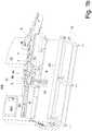
- FIGS. 1a and 2a The structure of the machine is best left by the FIGS. 1a and 2a of course, beyond that, of course, the view of FIG. 1b from below as well as the front view of the FIG. 2b and the supervision of Figure 2c :
- the transverse direction 11 is perpendicular to the passage direction 10 of the products, that is to say the conveying direction of the product conveyors 7, 7 ' , 7 " and of the tray conveyor 8.
- the product 1 b is pushed to the correct transverse position and aligned with respect to its rotational position about the vertical axis, ie especially for portions whose side edges are not aligned parallel to the direction of passage 10 .
- This last product conveyor 7 has in its end an obliquely downwardly facing course of the upper strand of this endlessly circulating product conveyor 7, which is a deflection roller with a very small diameter is deflected for the purpose of forming a discharge edge 7a as the end of this product conveyor .
- a product 1 a which is transported on the preferably at constant speed, at least during the ejection process running product conveyor 7 , runs at the end in the oblique area already obliquely down and continues due to its speed, this direction even after overflowing the discharge edge 7 a in free fall and should fall into an underlying Tray 2 , as in the following with reference to the FIGS. 5a, b is explained.
- Such a tray 2 is only in FIG. 2a located, and rests on the support plate 24 of a lifting device 9 which is capable of the support plate 24 from the in FIG. 2 lift shown lowered position until the mounted at a fixed height mask 4 dips with its walls in the tray 2 and its laterally encircling edge 2 a covers, if the tray 2 was previously just below the mask 4 .
- the support plate 24 can be moved away from the machine housing in a transverse position and longitudinal position exactly below the mask 4 , located in the FIGS. 1a . b and 2a . b is in the starting position for performing a discharge operation.
- the mask 4 can from this starting position in the direction of passage 10 by means of a mask conveyor 26 are moved horizontally with the over the discharge edge 7 a flying product 1 c, wherein the mask entrains the tray 2 in this direction because of the immersed in the tray 2 position.
- the mask 4 move with tray 2 preferably at the same speed in the direction of passage 10 as the on the discharge edge 7 a straight dropped product 1 c.
- the tray 2 is filled with a single dropping operation, with which a single product 1 c or a whole portion is dropped into the tray 2 , then the filled tray is lowered down until it disengages from the mask 4 , and via a first Trayor 8 and, if necessary. Another Trayfurer 8 'of the filled Tray 2 removed.
- the lowering of the tray 2 can also take place by means of a vertical movement of the right end portion of the tray conveyor 8 , if the tray 2 is then already on this.
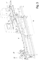
- FIG. 3 shows one opposite the FIGS. 1 a , b and 2 a, b, c to the left extended insertion machine, which is shown without products and trays, but on which it can be seen that by means of the product conveyor 8, the filled trays are transported to a doubling in the direction of passage 10 sealing station 27 , in which is sealed from above a ring around the upper opening 13 of the tray sealing film 3 , to close the filled tray 2 tight, as better understood FIG. 5e to recognize.
- the individual conveyors are mounted, located in the front view in the left part of the controller 50 with the display 50 a and a control unit 50 b and preferably also the whole machine with electrical power supply cabinet ,
- the tray 2 is generally rectangular, and has one around its upper opening 13 all-round, horizontally outwardly projecting edge 2 a, obliquely downwardly inwardly extending walls and a bottom 2 b, on which a suction material 14 lie which can absorb liquid such as meat juice well.
- the mask 4 has a continuous from top to bottom through opening 12, which is slightly smaller than the opening 13 of the tray 2.
- the through hole 12 of the mask 4 is also generally rectangular, from which also usually obliquely from top to bottom extend to the center inclined individual walls 4 b or a single ring extending around the passage opening 12 wall.
- the passage opening 12 of the mask 4 is also surrounded by a horizontally outwardly projecting edge 4 a.
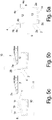
- the dimensioning of the mask 4 is adapted to the tray 2 such that - as in FIG. 5b represented by subsequent lifting of the tray 2 by means of a lifting device 9 of the tray 2 can be raised so far that the walls 4 b of the mask 4 dip into the opening 13 of the tray 2 and possibly also reach the bottom and the absorbent material 14 - or if such a suction material does not exist, the bottom of the tray - can contact if the walls of the mask are sufficiently high, which is not always the case.
- the contact causes a possibly at the lower edge of the peripheral wall 4b of the mask 4 forming liquid droplets 6 does not drop at any time, but targeted by zing. B. is absorbed by the absorbent material 14 .
- the horizontally projecting edge 4 a of the mask 4 is so wide that it completely covers the edge 2 a of the tray 2 .
- the filled Tray 2 is sealed and can be further picking and processing supplied.
- the tray 2 is moved back together with the mask and with this engaged horizontally into the starting position for dropping off FIG. 5b , And it is a dropping of one or more products in the tray until it is completely filled.
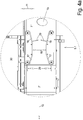
- each of the circumferential side conveyor 17 outwardly projecting paddles 29 are arranged at opposite positions of the belts of the side conveyor 17 , push these paddles 29 against the trailing edge of the product 1 b and thereby direct the product in the rotational position about the horizontal axis in the transverse direction from when the side conveyor 17 to run slightly faster than the product conveyor 7 ".
- the product 1 runs b with its front side against a pair of paddles 29, and is thereby also in its Rotational position aligned around the vertical axis.
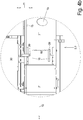
- FIG. 4b shows another transverse positioning device 5.2, in which in both side edge regions of the product conveyor 7 "in the height range above, in which the continuous product 1 b is reached, depending on a cross slide 16 is arranged, the front end face extends approximately in the direction 10 , and which can be moved by means of a slide punch 20 in the transverse direction 11 .
- the product 1 b passing through between the transverse slides 16 can be displaced and positioned in the transverse direction 11 by extension of one or both of the independently controllable sliding rams 20 by means of the respective transverse slide 16 .
- the slide punch 20 a limited distance in the direction 10 can be moved with the speed of the product 1 b or - which is not shown - are pivoted about an upright pivot axis, in which case, however, the product contacting end face of the cross slide 16 is preferably convex.
- a transverse position sensor 15 which determines the transverse position of the product 1 b passing by it, is arranged upstream of the transverse positioning device.
- This solution can serve to adjust the starting position of the cross slide 16 in the transverse direction 11 .
- the Querpositioniervoriques consists exclusively of such a transverse position sensor 15 , ie the transverse position of the product 1 b determined on the product conveyor, but not mechanically changed, but instead with the information of the transverse position of the tray 2 is set in the appropriate transverse position at the discharge point.
- the at the inlet is preferably carried out at such an angular velocity that the points of the two contact surfaces 31 a closest to one another move at the same speed in the direction of passage 10 as the product conveyor 7 ".
Landscapes
- Engineering & Computer Science (AREA)
- Mechanical Engineering (AREA)
- Life Sciences & Earth Sciences (AREA)
- Forests & Forestry (AREA)
- Specific Conveyance Elements (AREA)
- Auxiliary Devices For And Details Of Packaging Control (AREA)
Priority Applications (1)
| Application Number | Priority Date | Filing Date | Title |
|---|---|---|---|
| PL15183996T PL2993135T3 (pl) | 2014-09-05 | 2015-09-07 | Maszyna do wkładania i sposób wkładania |
Applications Claiming Priority (1)
| Application Number | Priority Date | Filing Date | Title |
|---|---|---|---|
| DE102014112840.0A DE102014112840B4 (de) | 2014-09-05 | 2014-09-05 | Einlegemaschine und Einlegeverfahren |
Publications (3)
| Publication Number | Publication Date |
|---|---|
| EP2993135A2 EP2993135A2 (de) | 2016-03-09 |
| EP2993135A3 EP2993135A3 (de) | 2016-05-25 |
| EP2993135B1 true EP2993135B1 (de) | 2017-08-23 |
Family
ID=54072695
Family Applications (1)
| Application Number | Title | Priority Date | Filing Date |
|---|---|---|---|
| EP15183996.6A Active EP2993135B1 (de) | 2014-09-05 | 2015-09-07 | Einlegemaschine und einlegeverfahren |
Country Status (5)
| Country | Link |
|---|---|
| EP (1) | EP2993135B1 (da) |
| DE (1) | DE102014112840B4 (da) |
| DK (1) | DK2993135T3 (da) |
| ES (1) | ES2643415T3 (da) |
| PL (1) | PL2993135T3 (da) |
Families Citing this family (1)
| Publication number | Priority date | Publication date | Assignee | Title |
|---|---|---|---|---|
| CN114474182B (zh) * | 2022-01-07 | 2024-07-09 | 南京玄策智能科技有限公司 | 一种胃管加工用线性裁剪设备 |
Family Cites Families (13)
| Publication number | Priority date | Publication date | Assignee | Title |
|---|---|---|---|---|
| US3354613A (en) * | 1965-04-28 | 1967-11-28 | Mahaffy & Harder Eng Co | Packaging apparatus with improved product loader |
| DE1960660U (de) | 1966-12-21 | 1967-05-18 | Vogt & Wolf G M B H | Verpackungsmaschine fuer fleischwaren und aufschnittwaren. |
| JPS52132989A (en) * | 1976-04-27 | 1977-11-08 | Dainippon Printing Co Ltd | Method of charging and packing material of small quantities |
| EP0104142A3 (de) * | 1982-09-16 | 1985-05-02 | Hollymatic AG Ingenbohl | Vorrichtung zum ortsgenauen Ablegen von Gegenständen |
| JPS61178315A (ja) | 1985-02-01 | 1986-08-11 | Rheon Autom Mach Co Ltd | 食品素材の移載装置 |
| CA2377198A1 (en) * | 2001-03-23 | 2002-09-23 | Kraft Foods Holdings, Inc. | Automated system and method for placing sliced food stacks in packages |
| DE10224237A1 (de) * | 2002-05-29 | 2003-12-11 | Convenience Food Sys Wallau | Verpackung |
| FR2846624B1 (fr) * | 2002-10-31 | 2005-06-17 | Dispac | Procede et un dispositif pour remplir des barquettes d'un produit alimentaire |
| GB0803432D0 (en) * | 2008-02-26 | 2008-04-02 | Panahi Abol | Loading machine |
| US20090241472A1 (en) * | 2008-03-03 | 2009-10-01 | Lindee Scott A | Food Patty Combining and Loading System |
| KR20110016852A (ko) | 2008-06-13 | 2011-02-18 | 타카이 토후 앤 소이 밀크 이큅먼트 컴퍼니 리미티드 | 두부류의 자동 패킹 장치 |
| DE102011101101A1 (de) * | 2011-05-10 | 2014-01-30 | Bizerba Gmbh & Co Kg | Schneidemaschine |
| EP3539739B1 (de) * | 2012-01-26 | 2024-04-17 | GEA Food Solutions Germany GmbH | Maschine zum slicen in die packung |
-
2014
- 2014-09-05 DE DE102014112840.0A patent/DE102014112840B4/de not_active Expired - Fee Related
-
2015
- 2015-09-07 EP EP15183996.6A patent/EP2993135B1/de active Active
- 2015-09-07 PL PL15183996T patent/PL2993135T3/pl unknown
- 2015-09-07 ES ES15183996.6T patent/ES2643415T3/es active Active
- 2015-09-07 DK DK15183996.6T patent/DK2993135T3/da active
Non-Patent Citations (1)
| Title |
|---|
| None * |
Also Published As
| Publication number | Publication date |
|---|---|
| EP2993135A2 (de) | 2016-03-09 |
| DK2993135T3 (da) | 2017-11-27 |
| PL2993135T3 (pl) | 2018-01-31 |
| ES2643415T3 (es) | 2017-11-22 |
| EP2993135A3 (de) | 2016-05-25 |
| DE102014112840A1 (de) | 2016-03-10 |
| DE102014112840B4 (de) | 2018-09-06 |
Similar Documents
| Publication | Publication Date | Title |
|---|---|---|
| EP2807004B2 (de) | Aufschneiden in die packung | |
| EP1647487B1 (de) | Verfahren und Vorrichtung zum Einlegen von Tabletten in die Höfe tiefgezogener Bodenfolie | |
| EP2692650B1 (de) | Schalenverschließmaschine | |
| DE102010061446A1 (de) | Intermittierend rotierende Maschine für das Füllen von Kapseln mit pharmazeutischen Produkten | |
| DE102010061447A1 (de) | Intermittierend rotierende Maschine für das füllen von Kapseln mit Pharmazeutischen Produkten | |
| DE102010061444A1 (de) | Intermittierend rotierende Maschine für das füllen von Kapseln mit Pharmazeutischen Produkten | |
| DE102009031516A1 (de) | Vorrichtung und Verfahren zum Gruppieren von Packungen | |
| WO2018229077A2 (de) | Verfahren und vorrichtung zum umgang mit nicht aufrecht stehenden artikeln eines artikelstroms unter vermeidung von störungen | |
| EP1713693A1 (de) | Verfahren und vorrichtung zum überführen von produkten aus einem vorratsgefäss in die näpfe einer folie | |
| DE102015105295B4 (de) | Einlegemaschine und Einlegeverfahren | |
| EP2103520B1 (de) | Behandlungseinrichtung und Verfahren zum Behandeln eines mit einem Schüttgut gefüllten offenen Sacks | |
| WO2017198768A2 (de) | Höhenförderer | |
| EP2993135B1 (de) | Einlegemaschine und einlegeverfahren | |
| EP3235743A1 (de) | Transporteinheit mit unterdruckvorrichtung und verfahren zum transportieren von schalen | |
| EP3757045B1 (de) | Abwerfen eines stückgutes von einem lastaufnahmemittel | |
| DE3536186C2 (de) | Vorrichtung zur Zuführung stabförmiger Gegenstände, beispielsweise Zigaretten, zu einer Behandlungsstation oder dergleichen | |
| EP4281397A1 (de) | Förderanlage zum fördern von fördergut | |
| DE102015003110A1 (de) | Vorrichtung und Verfahren zum Entladen von Roll- oder Wechselbehältern | |
| CH715814A1 (de) | Übergabesystem für Förderobjekte mit einer Fördereinrichtung und einer Übergabevorrichtung. | |
| DE1556752C3 (de) | Verfahren zur Bildung und Entnahme von Stapeln aus laufend angelieferten plattenförmigen Objekten, sowie Einrichtung zur Durchführung dieses Verfahrens | |
| DE2361049A1 (de) | Vorrichtung zum foerdern eines mengenstromes von zigaretten | |
| DE3524291A1 (de) | Kommissioniereinrichtung fuer waren | |
| AT393484B (de) | Vorrichtung zum drehen von packungen | |
| DE69305467T2 (de) | Gerät und Methode zum Einlegen eines zylindrischen Teiles in einem Behälter | |
| EP3822201A1 (de) | Fördervorrichtung und verfahren zum sortieren von stückgütern |
Legal Events
| Date | Code | Title | Description |
|---|---|---|---|
| PUAI | Public reference made under article 153(3) epc to a published international application that has entered the european phase |
Free format text: ORIGINAL CODE: 0009012 |
|
| AK | Designated contracting states |
Kind code of ref document: A2 Designated state(s): AL AT BE BG CH CY CZ DE DK EE ES FI FR GB GR HR HU IE IS IT LI LT LU LV MC MK MT NL NO PL PT RO RS SE SI SK SM TR |
|
| AX | Request for extension of the european patent |
Extension state: BA ME |
|
| PUAL | Search report despatched |
Free format text: ORIGINAL CODE: 0009013 |
|
| AK | Designated contracting states |
Kind code of ref document: A3 Designated state(s): AL AT BE BG CH CY CZ DE DK EE ES FI FR GB GR HR HU IE IS IT LI LT LU LV MC MK MT NL NO PL PT RO RS SE SI SK SM TR |
|
| AX | Request for extension of the european patent |
Extension state: BA ME |
|
| RIC1 | Information provided on ipc code assigned before grant |
Ipc: B65B 55/00 20060101ALI20160418BHEP Ipc: B65B 35/56 20060101ALI20160418BHEP Ipc: B65B 35/24 20060101ALI20160418BHEP Ipc: B65B 5/10 20060101ALI20160418BHEP Ipc: B26D 7/32 20060101ALI20160418BHEP Ipc: B65B 57/14 20060101ALI20160418BHEP Ipc: B65B 25/06 20060101AFI20160418BHEP Ipc: B65B 43/59 20060101ALI20160418BHEP Ipc: B65B 5/04 20060101ALI20160418BHEP Ipc: B65B 39/00 20060101ALI20160418BHEP Ipc: B65B 39/14 20060101ALI20160418BHEP Ipc: B65B 5/06 20060101ALI20160418BHEP |
|
| RAP1 | Party data changed (applicant data changed or rights of an application transferred) |
Owner name: ANTON & VOELKL PATENTE GMBH & CO. KG |
|
| 17P | Request for examination filed |
Effective date: 20161125 |
|
| RBV | Designated contracting states (corrected) |
Designated state(s): AL AT BE BG CH CY CZ DE DK EE ES FI FR GB GR HR HU IE IS IT LI LT LU LV MC MK MT NL NO PL PT RO RS SE SI SK SM TR |
|
| GRAP | Despatch of communication of intention to grant a patent |
Free format text: ORIGINAL CODE: EPIDOSNIGR1 |
|
| INTG | Intention to grant announced |
Effective date: 20170404 |
|
| RAP1 | Party data changed (applicant data changed or rights of an application transferred) |
Owner name: TVI ENTWICKLUNG UND PRODUKTION GMBH |
|
| GRAS | Grant fee paid |
Free format text: ORIGINAL CODE: EPIDOSNIGR3 |
|
| GRAA | (expected) grant |
Free format text: ORIGINAL CODE: 0009210 |
|
| AK | Designated contracting states |
Kind code of ref document: B1 Designated state(s): AL AT BE BG CH CY CZ DE DK EE ES FI FR GB GR HR HU IE IS IT LI LT LU LV MC MK MT NL NO PL PT RO RS SE SI SK SM TR |
|
| REG | Reference to a national code |
Ref country code: GB Ref legal event code: FG4D Free format text: NOT ENGLISH |
|
| REG | Reference to a national code |
Ref country code: CH Ref legal event code: EP |
|
| REG | Reference to a national code |
Ref country code: AT Ref legal event code: REF Ref document number: 921045 Country of ref document: AT Kind code of ref document: T Effective date: 20170915 |
|
| REG | Reference to a national code |
Ref country code: IE Ref legal event code: FG4D Free format text: LANGUAGE OF EP DOCUMENT: GERMAN |
|
| REG | Reference to a national code |
Ref country code: CH Ref legal event code: NV Representative=s name: BOVARD AG PATENT- UND MARKENANWAELTE, CH |
|
| REG | Reference to a national code |
Ref country code: DE Ref legal event code: R096 Ref document number: 502015001729 Country of ref document: DE |
|
| REG | Reference to a national code |
Ref country code: FR Ref legal event code: PLFP Year of fee payment: 3 |
|
| REG | Reference to a national code |
Ref country code: ES Ref legal event code: FG2A Ref document number: 2643415 Country of ref document: ES Kind code of ref document: T3 Effective date: 20171122 |
|
| REG | Reference to a national code |
Ref country code: DK Ref legal event code: T3 Effective date: 20171122 |
|
| REG | Reference to a national code |
Ref country code: NL Ref legal event code: FP |
|
| REG | Reference to a national code |
Ref country code: LT Ref legal event code: MG4D |
|
| PG25 | Lapsed in a contracting state [announced via postgrant information from national office to epo] |
Ref country code: LT Free format text: LAPSE BECAUSE OF FAILURE TO SUBMIT A TRANSLATION OF THE DESCRIPTION OR TO PAY THE FEE WITHIN THE PRESCRIBED TIME-LIMIT Effective date: 20170823 Ref country code: NO Free format text: LAPSE BECAUSE OF FAILURE TO SUBMIT A TRANSLATION OF THE DESCRIPTION OR TO PAY THE FEE WITHIN THE PRESCRIBED TIME-LIMIT Effective date: 20171123 Ref country code: SE Free format text: LAPSE BECAUSE OF FAILURE TO SUBMIT A TRANSLATION OF THE DESCRIPTION OR TO PAY THE FEE WITHIN THE PRESCRIBED TIME-LIMIT Effective date: 20170823 Ref country code: HR Free format text: LAPSE BECAUSE OF FAILURE TO SUBMIT A TRANSLATION OF THE DESCRIPTION OR TO PAY THE FEE WITHIN THE PRESCRIBED TIME-LIMIT Effective date: 20170823 |
|
| PG25 | Lapsed in a contracting state [announced via postgrant information from national office to epo] |
Ref country code: LV Free format text: LAPSE BECAUSE OF FAILURE TO SUBMIT A TRANSLATION OF THE DESCRIPTION OR TO PAY THE FEE WITHIN THE PRESCRIBED TIME-LIMIT Effective date: 20170823 Ref country code: RS Free format text: LAPSE BECAUSE OF FAILURE TO SUBMIT A TRANSLATION OF THE DESCRIPTION OR TO PAY THE FEE WITHIN THE PRESCRIBED TIME-LIMIT Effective date: 20170823 Ref country code: GR Free format text: LAPSE BECAUSE OF FAILURE TO SUBMIT A TRANSLATION OF THE DESCRIPTION OR TO PAY THE FEE WITHIN THE PRESCRIBED TIME-LIMIT Effective date: 20171124 Ref country code: BG Free format text: LAPSE BECAUSE OF FAILURE TO SUBMIT A TRANSLATION OF THE DESCRIPTION OR TO PAY THE FEE WITHIN THE PRESCRIBED TIME-LIMIT Effective date: 20171123 |
|
| PG25 | Lapsed in a contracting state [announced via postgrant information from national office to epo] |
Ref country code: RO Free format text: LAPSE BECAUSE OF FAILURE TO SUBMIT A TRANSLATION OF THE DESCRIPTION OR TO PAY THE FEE WITHIN THE PRESCRIBED TIME-LIMIT Effective date: 20170823 Ref country code: CZ Free format text: LAPSE BECAUSE OF FAILURE TO SUBMIT A TRANSLATION OF THE DESCRIPTION OR TO PAY THE FEE WITHIN THE PRESCRIBED TIME-LIMIT Effective date: 20170823 |
|
| REG | Reference to a national code |
Ref country code: DE Ref legal event code: R097 Ref document number: 502015001729 Country of ref document: DE |
|
| PG25 | Lapsed in a contracting state [announced via postgrant information from national office to epo] |
Ref country code: MC Free format text: LAPSE BECAUSE OF FAILURE TO SUBMIT A TRANSLATION OF THE DESCRIPTION OR TO PAY THE FEE WITHIN THE PRESCRIBED TIME-LIMIT Effective date: 20170823 Ref country code: SK Free format text: LAPSE BECAUSE OF FAILURE TO SUBMIT A TRANSLATION OF THE DESCRIPTION OR TO PAY THE FEE WITHIN THE PRESCRIBED TIME-LIMIT Effective date: 20170823 Ref country code: SM Free format text: LAPSE BECAUSE OF FAILURE TO SUBMIT A TRANSLATION OF THE DESCRIPTION OR TO PAY THE FEE WITHIN THE PRESCRIBED TIME-LIMIT Effective date: 20170823 Ref country code: EE Free format text: LAPSE BECAUSE OF FAILURE TO SUBMIT A TRANSLATION OF THE DESCRIPTION OR TO PAY THE FEE WITHIN THE PRESCRIBED TIME-LIMIT Effective date: 20170823 |
|
| REG | Reference to a national code |
Ref country code: IE Ref legal event code: MM4A |
|
| REG | Reference to a national code |
Ref country code: BE Ref legal event code: MM Effective date: 20170930 |
|
| PG25 | Lapsed in a contracting state [announced via postgrant information from national office to epo] |
Ref country code: LU Free format text: LAPSE BECAUSE OF NON-PAYMENT OF DUE FEES Effective date: 20170907 |
|
| PLBE | No opposition filed within time limit |
Free format text: ORIGINAL CODE: 0009261 |
|
| STAA | Information on the status of an ep patent application or granted ep patent |
Free format text: STATUS: NO OPPOSITION FILED WITHIN TIME LIMIT |
|
| PG25 | Lapsed in a contracting state [announced via postgrant information from national office to epo] |
Ref country code: IE Free format text: LAPSE BECAUSE OF NON-PAYMENT OF DUE FEES Effective date: 20170907 |
|
| 26N | No opposition filed |
Effective date: 20180524 |
|
| PG25 | Lapsed in a contracting state [announced via postgrant information from national office to epo] |
Ref country code: SI Free format text: LAPSE BECAUSE OF FAILURE TO SUBMIT A TRANSLATION OF THE DESCRIPTION OR TO PAY THE FEE WITHIN THE PRESCRIBED TIME-LIMIT Effective date: 20170823 Ref country code: BE Free format text: LAPSE BECAUSE OF NON-PAYMENT OF DUE FEES Effective date: 20170930 |
|
| REG | Reference to a national code |
Ref country code: FR Ref legal event code: PLFP Year of fee payment: 4 |
|
| PG25 | Lapsed in a contracting state [announced via postgrant information from national office to epo] |
Ref country code: MT Free format text: LAPSE BECAUSE OF FAILURE TO SUBMIT A TRANSLATION OF THE DESCRIPTION OR TO PAY THE FEE WITHIN THE PRESCRIBED TIME-LIMIT Effective date: 20170823 |
|
| PG25 | Lapsed in a contracting state [announced via postgrant information from national office to epo] |
Ref country code: HU Free format text: LAPSE BECAUSE OF FAILURE TO SUBMIT A TRANSLATION OF THE DESCRIPTION OR TO PAY THE FEE WITHIN THE PRESCRIBED TIME-LIMIT; INVALID AB INITIO Effective date: 20150907 |
|
| PG25 | Lapsed in a contracting state [announced via postgrant information from national office to epo] |
Ref country code: CY Free format text: LAPSE BECAUSE OF FAILURE TO SUBMIT A TRANSLATION OF THE DESCRIPTION OR TO PAY THE FEE WITHIN THE PRESCRIBED TIME-LIMIT Effective date: 20170823 |
|
| PG25 | Lapsed in a contracting state [announced via postgrant information from national office to epo] |
Ref country code: MK Free format text: LAPSE BECAUSE OF FAILURE TO SUBMIT A TRANSLATION OF THE DESCRIPTION OR TO PAY THE FEE WITHIN THE PRESCRIBED TIME-LIMIT Effective date: 20170823 |
|
| PG25 | Lapsed in a contracting state [announced via postgrant information from national office to epo] |
Ref country code: TR Free format text: LAPSE BECAUSE OF FAILURE TO SUBMIT A TRANSLATION OF THE DESCRIPTION OR TO PAY THE FEE WITHIN THE PRESCRIBED TIME-LIMIT Effective date: 20170823 |
|
| PG25 | Lapsed in a contracting state [announced via postgrant information from national office to epo] |
Ref country code: PT Free format text: LAPSE BECAUSE OF FAILURE TO SUBMIT A TRANSLATION OF THE DESCRIPTION OR TO PAY THE FEE WITHIN THE PRESCRIBED TIME-LIMIT Effective date: 20170823 |
|
| REG | Reference to a national code |
Ref country code: DE Ref legal event code: R081 Ref document number: 502015001729 Country of ref document: DE Owner name: TVI ENTWICKLUNG UND PRODUKTION GMBH, DE Free format text: FORMER OWNER: TVI ENTWICKLUNG UND PRODUKTION GMBH, 83737 IRSCHENBERG, DE Ref country code: DE Ref legal event code: R082 Ref document number: 502015001729 Country of ref document: DE Representative=s name: WEICKMANN & WEICKMANN PATENT- UND RECHTSANWAEL, DE |
|
| PG25 | Lapsed in a contracting state [announced via postgrant information from national office to epo] |
Ref country code: AL Free format text: LAPSE BECAUSE OF FAILURE TO SUBMIT A TRANSLATION OF THE DESCRIPTION OR TO PAY THE FEE WITHIN THE PRESCRIBED TIME-LIMIT Effective date: 20170823 |
|
| P01 | Opt-out of the competence of the unified patent court (upc) registered |
Effective date: 20230512 |
|
| REG | Reference to a national code |
Ref country code: CH Ref legal event code: U11 Free format text: ST27 STATUS EVENT CODE: U-0-0-U10-U11 (AS PROVIDED BY THE NATIONAL OFFICE) Effective date: 20251001 |
|
| PGFP | Annual fee paid to national office [announced via postgrant information from national office to epo] |
Ref country code: FI Payment date: 20250922 Year of fee payment: 11 |
|
| PGFP | Annual fee paid to national office [announced via postgrant information from national office to epo] |
Ref country code: DK Payment date: 20250922 Year of fee payment: 11 Ref country code: DE Payment date: 20250919 Year of fee payment: 11 |
|
| PGFP | Annual fee paid to national office [announced via postgrant information from national office to epo] |
Ref country code: NL Payment date: 20250922 Year of fee payment: 11 Ref country code: PL Payment date: 20250827 Year of fee payment: 11 |
|
| PGFP | Annual fee paid to national office [announced via postgrant information from national office to epo] |
Ref country code: GB Payment date: 20250923 Year of fee payment: 11 |
|
| PGFP | Annual fee paid to national office [announced via postgrant information from national office to epo] |
Ref country code: AT Payment date: 20250918 Year of fee payment: 11 Ref country code: FR Payment date: 20250924 Year of fee payment: 11 |
|
| PGFP | Annual fee paid to national office [announced via postgrant information from national office to epo] |
Ref country code: IS Payment date: 20250922 Year of fee payment: 11 |
|
| PGFP | Annual fee paid to national office [announced via postgrant information from national office to epo] |
Ref country code: IT Payment date: 20250930 Year of fee payment: 11 |
|
| PGFP | Annual fee paid to national office [announced via postgrant information from national office to epo] |
Ref country code: CH Payment date: 20251001 Year of fee payment: 11 |
|
| PGFP | Annual fee paid to national office [announced via postgrant information from national office to epo] |
Ref country code: ES Payment date: 20251020 Year of fee payment: 11 |