EP2993076A1 - Armature et siege de vehicule - Google Patents
Armature et siege de vehicule Download PDFInfo
- Publication number
- EP2993076A1 EP2993076A1 EP15176629.2A EP15176629A EP2993076A1 EP 2993076 A1 EP2993076 A1 EP 2993076A1 EP 15176629 A EP15176629 A EP 15176629A EP 2993076 A1 EP2993076 A1 EP 2993076A1
- Authority
- EP
- European Patent Office
- Prior art keywords
- fitting
- axial securing
- axial
- stiffening structure
- ring gear
- Prior art date
- Legal status (The legal status is an assumption and is not a legal conclusion. Google has not performed a legal analysis and makes no representation as to the accuracy of the status listed.)
- Granted
Links
- 239000011324 bead Substances 0.000 claims description 5
- 239000002184 metal Substances 0.000 claims description 3
- 230000005540 biological transmission Effects 0.000 description 5
- 238000004519 manufacturing process Methods 0.000 description 4
- 238000003466 welding Methods 0.000 description 4
- 239000000463 material Substances 0.000 description 2
- 230000007246 mechanism Effects 0.000 description 2
- 238000000034 method Methods 0.000 description 2
- 230000008569 process Effects 0.000 description 2
- 238000004080 punching Methods 0.000 description 2
- 238000010521 absorption reaction Methods 0.000 description 1
- 230000006835 compression Effects 0.000 description 1
- 238000007906 compression Methods 0.000 description 1
- 230000006735 deficit Effects 0.000 description 1
- 238000005304 joining Methods 0.000 description 1
- 230000004048 modification Effects 0.000 description 1
- 238000012986 modification Methods 0.000 description 1
- 230000009467 reduction Effects 0.000 description 1
- 230000003014 reinforcing effect Effects 0.000 description 1
- 230000000452 restraining effect Effects 0.000 description 1
- 238000005476 soldering Methods 0.000 description 1
Images


Classifications
-
- B—PERFORMING OPERATIONS; TRANSPORTING
- B60—VEHICLES IN GENERAL
- B60N—SEATS SPECIALLY ADAPTED FOR VEHICLES; VEHICLE PASSENGER ACCOMMODATION NOT OTHERWISE PROVIDED FOR
- B60N2/00—Seats specially adapted for vehicles; Arrangement or mounting of seats in vehicles
- B60N2/02—Seats specially adapted for vehicles; Arrangement or mounting of seats in vehicles the seat or part thereof being movable, e.g. adjustable
- B60N2/22—Seats specially adapted for vehicles; Arrangement or mounting of seats in vehicles the seat or part thereof being movable, e.g. adjustable the back-rest being adjustable
- B60N2/225—Seats specially adapted for vehicles; Arrangement or mounting of seats in vehicles the seat or part thereof being movable, e.g. adjustable the back-rest being adjustable by cycloidal or planetary mechanisms
- B60N2/2252—Seats specially adapted for vehicles; Arrangement or mounting of seats in vehicles the seat or part thereof being movable, e.g. adjustable the back-rest being adjustable by cycloidal or planetary mechanisms in which the central axis of the gearing lies inside the periphery of an orbital gear, e.g. one gear without sun gear
-
- B—PERFORMING OPERATIONS; TRANSPORTING
- B60—VEHICLES IN GENERAL
- B60N—SEATS SPECIALLY ADAPTED FOR VEHICLES; VEHICLE PASSENGER ACCOMMODATION NOT OTHERWISE PROVIDED FOR
- B60N2/00—Seats specially adapted for vehicles; Arrangement or mounting of seats in vehicles
- B60N2/02—Seats specially adapted for vehicles; Arrangement or mounting of seats in vehicles the seat or part thereof being movable, e.g. adjustable
- B60N2/22—Seats specially adapted for vehicles; Arrangement or mounting of seats in vehicles the seat or part thereof being movable, e.g. adjustable the back-rest being adjustable
- B60N2/225—Seats specially adapted for vehicles; Arrangement or mounting of seats in vehicles the seat or part thereof being movable, e.g. adjustable the back-rest being adjustable by cycloidal or planetary mechanisms
- B60N2/2254—Seats specially adapted for vehicles; Arrangement or mounting of seats in vehicles the seat or part thereof being movable, e.g. adjustable the back-rest being adjustable by cycloidal or planetary mechanisms provided with braking systems
-
- B—PERFORMING OPERATIONS; TRANSPORTING
- B60—VEHICLES IN GENERAL
- B60N—SEATS SPECIALLY ADAPTED FOR VEHICLES; VEHICLE PASSENGER ACCOMMODATION NOT OTHERWISE PROVIDED FOR
- B60N2/00—Seats specially adapted for vehicles; Arrangement or mounting of seats in vehicles
- B60N2/68—Seat frames
- B60N2/682—Joining means
Definitions
- the invention relates to a fitting and a vehicle seat.
- Vehicle seats with a backrest adjustment or backrest tilt adjustment have a gearbox, often designed as a wobble mechanism, for adjusting the backrest.
- the gearbox usually comprises an internally toothed ring gear and an externally toothed spur gear.
- DE 28 34 529 C2 discloses a hinge fitting for seats with adjustable backrest, wherein a bearing plate is provided as axial securing.
- the bearing plate has two diametrically opposed bends, which are welded at axial compression with a predetermined force at their ends with a fitting.
- DE 10 2011 113 748 A1 describes a method for producing a vehicle seat fitting, in which a plain bearing bush is pressed in an axial direction in a receptacle of a first fitting part, wherein the pressed plain bearing bush has a radially projecting securing region.
- DE 10 2011 075 183 A1 discloses a drive for an adjustment of a motor vehicle seat with a drive motor and a two-stage reduction gear on.
- a flat cover plate is provided for supporting the transmission elements in the axial direction.
- the invention is based on the object to increase the crash safety.
- the fitting according to the invention in particular a Lehneneinstellbeschlag for a vehicle seat, comprises a first fitting on which a ring gear is arranged with internal teeth, a relative to the first fitting part about an axial longitudinal axis of the fitting rotatable second fitting part on which a ring gear engaging in the spur gear is arranged and a fixed to the ring gear axial securing, wherein the spur gear between the ring gear and the axial securing is secured in the axial direction.
- the axial securing has at least one stiffening structure.
- the axial lock offers increased load absorption in the event of an accident or crash.
- This is achieved in that the stiffening structure increases the rigidity of the axial securing in the axial direction.
- the area moment of inertia of the axial securing is increased by the stiffening structure.
- the rigidity of the axial securing can be increased without an increased sheet thickness, so that in the event of a crash, the teeth remain in better engagement.
- the stiffening structure can be arranged on an inner radius of the axial securing. This arrangement of the stiffening structure is particularly effective, since the axial securing is usually attached at its outer radius, for example by welding to the ring gear, so that the axial securing is now stiffened at both ends.
- the stiffening structure can be rotationally symmetrical to the fitting axis. As a result, the rigidity or the area moment of inertia of the axial securing increases symmetrically over the entire circumference, so that there is no preferred direction. Thus, the crash safety over the entire angular range is improved.
- the stiffening structure can be provided in regions, in order to selectively reinforce certain angular ranges.
- the stiffening structure may have an angled collar. This structure is easy to manufacture, for example by a stamping or punching process and offers a high rigidity.
- the stiffening structure may have a bead.
- the bead also offers high rigidity with simple production.
- the stiffening structure may be formed integrally with the axial securing. This allows easy production. For example, when punching the axial securing the stiffening structure can be generated directly.
- the stiffening structure may be attached to the axial securing. In this way, the stiffening structure can be secured by an additional joining process, for example by soldering or welding to the axial securing. This can be advantageous if, for example, different materials for the axial securing and the stiffening structure are desired.
- the axial securing can consist of a metal sheet.
- Metallic sheet already offers a good basic stiffness and can be connected in a simple manner, for example by welding, with usually metallic components of the fitting.
- the vehicle seat according to the invention comprises a seat part and an adjustable backrest and a fitting, as described above.
- the same advantages and modifications apply as described above.
- the first fitting part can be arranged on the backrest and the second fitting part can be arranged on the seat part. This arrangement allows good power transmission and stability.
- FIG. 1 shows a vehicle seat 10 according to the invention or, more precisely, the backrest 12 of the backrest 12, a supporting structure is shown.
- the backrest 12 is attached to a seat part, not shown, which is anchored by means of a sliding mechanism to the vehicle body, for example.
- the backrest 12 can be adjusted about an axis of rotation Y relative to the seat part, that is pivoted or tilted.
- the backrest 12 is connected via two fittings 14 with the seat part.
- the backrest 12 exemplified here in an exploded view comprises a head plate or an upper crosspiece 16, two side parts or side bars 18 and a lower cross plate or a lower crosspiece 20.
- the individual parts of the backrest 12 are joined together, for example, by welding.
- the description applies both to the left fitting, which is arranged in the region of the left side part 18, and the right fitting, which is arranged in the region of the right side part 18.
- the left fitting and the right fitting may be identical or reversed.
- the fitting 14 includes, inter alia, a ring gear 22 and a spur gear 24.
- the ring gear 22 is assigned to a side part 18 or is attached to the side part. Thus, the ring gear 22 is restraining part.
- the spur gear 24 is associated with the seat part, not shown, that is, it is connected to this. Thus, the spur gear 24 is fixed to the seat part.
- the ring gear 22 with its internal teeth and the spur gear 24 with its external teeth engage each other.
- the ring gear 22 is connected via a not shown first fitting part with the backrest 12.
- the spur gear 24 is connected via a second fitting part 26 with the seat part.
- adapter parts can be used. It is also possible that one or both wheels 22, 24 are attached directly to elements of the seat. Then the wheels 22, 24, so to speak, the fitting parts.
- the fitting 14 is therefore in the power flow between the backrest 12 and the seat part, which is why the ring gear 22 and the spur gear 24 are preferably made of metal.
- the left side part 18 and also the right side part 18 have a passage opening 28 in a lower region, that is to say in the region of the fitting 14.
- the passage opening 28 is formed concentrically to the axis of rotation or fitting axis Y and dimensioned in size such that a part of the spur gear 24 and / or a part of the second fitting part 26 can be accommodated.
- a transmission rod not shown here, extends through the passage opening 28. The transmission rod connects the two fittings 14 to one another.
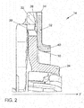
- FIG. 2 is a sectional view of the fitting 14 is shown.
- the ring gear 22 and the spur gear 24 engage in a toothing 30 in each other.
- An axial securing device 32 is provided.
- the axial securing device 32 is fastened to the ring gear 22 with an outer radius 34 or outer circumference, for example welded.
- the axial securing 32 and the ring gear 22 form an interior space 38, which is spaced from the axis of rotation Y or longitudinal axis.
- the interior 38 has an extension in the axial direction Y, which allows a recording of the spur gear 24.
- the spur gear 24 is normally arranged without contact in the axial direction Y in the interior 38.
- FIG. 2 is shown a crash case in which the fitting 24 is exposed to considerable forces and moments.
- the radial dimension of the inner space 38 is at least such that the toothing 30 lies in the inner space 38.
- the radial extent of the inner space 38 can be adjusted.
- the axial securing 32 has a stiffening structure 40 in the form of an angled collar.
- the collar runs parallel to the axis of rotation Y.
- the collar is located on the side facing away from the spur gear 24, so that no impairment of the movement of the spur gear 24 takes place.
- the stiffening structure 40 increases the rigidity of the axial securing 32 in the direction of the axis of rotation Y.
- the axial securing 32 in the in FIG. 2 Crash case record higher forces in the axial direction. This causes the gearing 30 to remain engaged for transmission of forces and moments.
- FIG. 3 the fitting 14 is shown in perspective.
- the spur gear 24 is at least in partial engagement with the toothing of the ring gear 22.
- the axial securing 32 is fixedly connected to the ring gear 22 at its outer end, that is, radially outer end.
- the stiffening structure 40 is arranged at the free, inner, that is, radially inner end.
- the stiffening structure 40 is free of the second fitting part 26, so that a relative movement between the two elements is possible.
- FIG. 4 a first embodiment of the axial securing 32 is shown.
- the axial securing 32 has substantially the shape of an axial securing with an outer radius 34 and an inner radius 36.
- the two radii 34, 36 define an axial securing surface 42.
- the inner radius 36 encloses an opening 44 through which parts of the spur gear 24 and other elements of the fitting 14.
- the annular surface 42 has a smaller radial extent than the opening 44. This allows weight and material savings.
- a fastening region 46 for fastening the axial securing means 32 to the side sword 18 is arranged. Except for the optional mounting portion 46, the axial securing 32 has the form of a rotationally symmetrical axial securing.
- the stiffening structure 40 is designed here rotationally symmetrical. Alternatively, the stiffening structure 40 may be executed only in sections or sections. In this case, the stiffening structure does not extend over the entire circumference.
- FIG. 5 a further embodiment of the axial securing 32 is shown.
- This axial securing 32 corresponds essentially to the one in FIG. 4 illustrated axial securing.
- the attachment area is off FIG. 4 not provided, so that the axial securing 32 has the shape of a circular ring.
- the stiffening structure 40 is formed as a bead or depression.
- the stiffening structure 40 is not at the inner radius 36, but in the annular surface 42 of the axial securing 32nd
- a stiffening structure in the form of a collar or other survey is also arranged on the annular surface 42, as the bead in FIG. 6 ,
- the stiffening structure 40 is shown in one piece in the figures. Alternatively, the stiffening structure 40 may consist of several individual parts or elements. For example, a plurality of concentric stiffening points may be provided, preferably extending from the outer radius 34 to the inner radius 36.
Landscapes
- Engineering & Computer Science (AREA)
- Aviation & Aerospace Engineering (AREA)
- Transportation (AREA)
- Mechanical Engineering (AREA)
- Chairs For Special Purposes, Such As Reclining Chairs (AREA)
- Seats For Vehicles (AREA)
Priority Applications (1)
| Application Number | Priority Date | Filing Date | Title |
|---|---|---|---|
| PL15176629T PL2993076T3 (pl) | 2014-08-26 | 2015-07-14 | Okucie i siedzenie pojazdu |
Applications Claiming Priority (1)
| Application Number | Priority Date | Filing Date | Title |
|---|---|---|---|
| DE102014216952.6A DE102014216952A1 (de) | 2014-08-26 | 2014-08-26 | Beschlag und Fahrzeugsitz |
Publications (2)
| Publication Number | Publication Date |
|---|---|
| EP2993076A1 true EP2993076A1 (fr) | 2016-03-09 |
| EP2993076B1 EP2993076B1 (fr) | 2019-10-16 |
Family
ID=53541622
Family Applications (1)
| Application Number | Title | Priority Date | Filing Date |
|---|---|---|---|
| EP15176629.2A Active EP2993076B1 (fr) | 2014-08-26 | 2015-07-14 | Armature et siege de vehicule |
Country Status (4)
| Country | Link |
|---|---|
| EP (1) | EP2993076B1 (fr) |
| CN (1) | CN105383337B (fr) |
| DE (1) | DE102014216952A1 (fr) |
| PL (1) | PL2993076T3 (fr) |
Families Citing this family (2)
| Publication number | Priority date | Publication date | Assignee | Title |
|---|---|---|---|---|
| DE102016226144B4 (de) * | 2016-10-12 | 2021-09-16 | Adient Engineering and IP GmbH | Antriebsanordnung und Verfahren zu deren Herstellung sowie Fahrzeugsitz |
| KR20220049277A (ko) * | 2020-10-14 | 2022-04-21 | 현대트랜시스 주식회사 | 시트 리클라이닝 장치 |
Citations (7)
| Publication number | Priority date | Publication date | Assignee | Title |
|---|---|---|---|---|
| DE2834529C2 (fr) | 1978-08-07 | 1993-02-04 | Keiper Automobiltechnik Gmbh & Co Kg, 5630 Remscheid, De | |
| DE4129515A1 (de) * | 1991-09-05 | 1993-03-11 | Rentrop Hubbert & Wagner | Gelenkbeschlag fuer kraftfahrzeugsitze |
| FR2962385A1 (fr) * | 2010-07-07 | 2012-01-13 | Faurecia Sieges Automobile | Mecanisme d'articulation et siege de vehicule comportant un tel mecanisme. |
| FR2962945A1 (fr) * | 2010-07-20 | 2012-01-27 | Faurecia Sieges Automobile | Mecanisme d'articulation et siege de vehicule comportant un tel mecanisme. |
| DE102011075183A1 (de) | 2010-08-31 | 2012-03-01 | Brose Fahrzeugteile Gmbh & Co. Kg, Coburg | Verstellantrieb für eine Verstelleinrichtung eines Kraftfahrzeugsitzes |
| DE102010043626A1 (de) * | 2010-11-09 | 2012-05-10 | Brose Fahrzeugteile Gmbh & Co. Kommanditgesellschaft, Coburg | Beschlag für einen Fahrzeugsitz mit daran angeordnetem Verstärkungsteil |
| DE102011113748A1 (de) | 2011-09-14 | 2013-03-14 | Keiper Gmbh & Co. Kg | Verfahren zur Herstellung eines Fahrzeugsitz-Beschlags |
Family Cites Families (6)
| Publication number | Priority date | Publication date | Assignee | Title |
|---|---|---|---|---|
| DE8601156U1 (fr) * | 1986-01-18 | 1987-01-08 | Keiper Recaro Gmbh & Co, 5630 Remscheid, De | |
| FR2915436B1 (fr) * | 2007-04-26 | 2009-07-10 | Faurecia Sieges Automobile | Mecanisme d'articulation et siege de vehicule comportant un tel mecanisme. |
| DE202009017811U1 (de) * | 2009-11-10 | 2010-07-08 | Keiper Gmbh & Co. Kg | Beschlag für einen Fahrzeugsitz |
| DE102012212137B4 (de) * | 2012-01-13 | 2022-03-10 | Keiper Seating Mechanisms Co., Ltd. | Neigungsverstellvorrichtung für einen Sitz |
| CN202911582U (zh) * | 2012-10-23 | 2013-05-01 | 江苏力乐汽车部件股份有限公司 | 汽车座椅调角器 |
| DE102012111941B4 (de) * | 2012-12-07 | 2022-03-03 | Keiper Seating Mechanisms Co., Ltd. | Sitzbeschlag für einen Kraftfahrzeugsitz |
-
2014
- 2014-08-26 DE DE102014216952.6A patent/DE102014216952A1/de not_active Withdrawn
-
2015
- 2015-07-14 PL PL15176629T patent/PL2993076T3/pl unknown
- 2015-07-14 EP EP15176629.2A patent/EP2993076B1/fr active Active
- 2015-08-26 CN CN201510529126.2A patent/CN105383337B/zh active Active
Patent Citations (7)
| Publication number | Priority date | Publication date | Assignee | Title |
|---|---|---|---|---|
| DE2834529C2 (fr) | 1978-08-07 | 1993-02-04 | Keiper Automobiltechnik Gmbh & Co Kg, 5630 Remscheid, De | |
| DE4129515A1 (de) * | 1991-09-05 | 1993-03-11 | Rentrop Hubbert & Wagner | Gelenkbeschlag fuer kraftfahrzeugsitze |
| FR2962385A1 (fr) * | 2010-07-07 | 2012-01-13 | Faurecia Sieges Automobile | Mecanisme d'articulation et siege de vehicule comportant un tel mecanisme. |
| FR2962945A1 (fr) * | 2010-07-20 | 2012-01-27 | Faurecia Sieges Automobile | Mecanisme d'articulation et siege de vehicule comportant un tel mecanisme. |
| DE102011075183A1 (de) | 2010-08-31 | 2012-03-01 | Brose Fahrzeugteile Gmbh & Co. Kg, Coburg | Verstellantrieb für eine Verstelleinrichtung eines Kraftfahrzeugsitzes |
| DE102010043626A1 (de) * | 2010-11-09 | 2012-05-10 | Brose Fahrzeugteile Gmbh & Co. Kommanditgesellschaft, Coburg | Beschlag für einen Fahrzeugsitz mit daran angeordnetem Verstärkungsteil |
| DE102011113748A1 (de) | 2011-09-14 | 2013-03-14 | Keiper Gmbh & Co. Kg | Verfahren zur Herstellung eines Fahrzeugsitz-Beschlags |
Also Published As
| Publication number | Publication date |
|---|---|
| EP2993076B1 (fr) | 2019-10-16 |
| PL2993076T3 (pl) | 2020-05-18 |
| DE102014216952A1 (de) | 2016-03-03 |
| CN105383337A (zh) | 2016-03-09 |
| CN105383337B (zh) | 2019-01-08 |
Similar Documents
| Publication | Publication Date | Title |
|---|---|---|
| EP1590226B1 (fr) | Dispositif de serrage pour colonne de direction | |
| DE102004011268B3 (de) | Neigungsverstellbeschlag für die Rückenlehne eines Kraftfahrzeugsitzes | |
| DE10312140B4 (de) | Feststell- und Neigungsverstellvorrichtung für Beschläge | |
| EP2376309B1 (fr) | Siège de véhicule, en particulier siège de véhicule automobile | |
| EP3492312A1 (fr) | Unité de réglage longitudinal d'un siège, en particulier d'un siège dans un véhicule automobile | |
| DE102014208852C5 (de) | Doppelbeschlag für einen Fahrzeugsitz und Fahrzeugsitz | |
| DE102009052512A1 (de) | Neigungsversteller für Fahrzeuge | |
| DE102017108206B4 (de) | Verstellanordnung für eine Verstelleinrichtung eines Fahrzeugsitzes, Verfahren zum Herstellen einer derartigen Verstellanordnung sowie Fahrzeugsitz | |
| DE102014107292B3 (de) | Lenksäule für ein Kraftfahrzeug | |
| DE4420251A1 (de) | Reibungskupplung | |
| EP2993076B1 (fr) | Armature et siege de vehicule | |
| DE102009010689A1 (de) | Höhenverstellung mit einem mehrteilig ausgeführten Abtriebsmittel | |
| DE102012204354B3 (de) | Stützstruktur eines Planetenradträgers | |
| DE102010021744A1 (de) | Verfahren zur Montage eines Fahrzeugsitzes | |
| EP3414126B1 (fr) | Procédé pour influer sur un déplacement vers l'arrière d'un siège et siège correspondant | |
| DE102013220659B4 (de) | Fahrzeugsitz, insbesondere Kraftfahrzeugsitz | |
| DE102019118258A1 (de) | Fahrzeugsitz-Strukturbauteil und Fahrzeugsitz | |
| DE102015216054A1 (de) | Verstelleinrichtung für einen Fahrzeugsitz | |
| DE19533453C2 (de) | Beschlag zur Neigungseinstellung der Rückenlehne eines Sitzes, insbesondere eines Kraftfahrzeugsitzes | |
| EP3911553B1 (fr) | Colonne de direction pour un véhicule automobile | |
| EP2613964B1 (fr) | Siège de véhicule avec un arbre, fixé axialement | |
| DE10203006A1 (de) | Beschlag für einen Fahrzeugsitz | |
| DE102013201514A1 (de) | Sitzrahmen eines Fahrzeugsitzes | |
| DE102004061062A1 (de) | Beschlag für einen Fahrzeugsitz | |
| EP3759374B1 (fr) | Équipement de pendule à force centrifuge à poulie élastique ondulée ; poulie d'embrayage et chaîne cinématique |
Legal Events
| Date | Code | Title | Description |
|---|---|---|---|
| PUAI | Public reference made under article 153(3) epc to a published international application that has entered the european phase |
Free format text: ORIGINAL CODE: 0009012 |
|
| AK | Designated contracting states |
Kind code of ref document: A1 Designated state(s): AL AT BE BG CH CY CZ DE DK EE ES FI FR GB GR HR HU IE IS IT LI LT LU LV MC MK MT NL NO PL PT RO RS SE SI SK SM TR |
|
| AX | Request for extension of the european patent |
Extension state: BA ME |
|
| 17P | Request for examination filed |
Effective date: 20160909 |
|
| RBV | Designated contracting states (corrected) |
Designated state(s): AL AT BE BG CH CY CZ DE DK EE ES FI FR GB GR HR HU IE IS IT LI LT LU LV MC MK MT NL NO PL PT RO RS SE SI SK SM TR |
|
| STAA | Information on the status of an ep patent application or granted ep patent |
Free format text: STATUS: EXAMINATION IS IN PROGRESS |
|
| 17Q | First examination report despatched |
Effective date: 20180627 |
|
| REG | Reference to a national code |
Ref country code: DE Ref legal event code: R079 Ref document number: 502015010652 Country of ref document: DE Free format text: PREVIOUS MAIN CLASS: B60N0002225000 Ipc: B60N0002680000 |
|
| RIC1 | Information provided on ipc code assigned before grant |
Ipc: B60N 2/225 20060101ALI20190703BHEP Ipc: B60N 2/68 20060101AFI20190703BHEP |
|
| GRAP | Despatch of communication of intention to grant a patent |
Free format text: ORIGINAL CODE: EPIDOSNIGR1 |
|
| STAA | Information on the status of an ep patent application or granted ep patent |
Free format text: STATUS: GRANT OF PATENT IS INTENDED |
|
| GRAS | Grant fee paid |
Free format text: ORIGINAL CODE: EPIDOSNIGR3 |
|
| INTG | Intention to grant announced |
Effective date: 20190814 |
|
| GRAA | (expected) grant |
Free format text: ORIGINAL CODE: 0009210 |
|
| STAA | Information on the status of an ep patent application or granted ep patent |
Free format text: STATUS: THE PATENT HAS BEEN GRANTED |
|
| AK | Designated contracting states |
Kind code of ref document: B1 Designated state(s): AL AT BE BG CH CY CZ DE DK EE ES FI FR GB GR HR HU IE IS IT LI LT LU LV MC MK MT NL NO PL PT RO RS SE SI SK SM TR |
|
| REG | Reference to a national code |
Ref country code: GB Ref legal event code: FG4D Free format text: NOT ENGLISH |
|
| REG | Reference to a national code |
Ref country code: CH Ref legal event code: EP |
|
| REG | Reference to a national code |
Ref country code: DE Ref legal event code: R096 Ref document number: 502015010652 Country of ref document: DE |
|
| REG | Reference to a national code |
Ref country code: IE Ref legal event code: FG4D Free format text: LANGUAGE OF EP DOCUMENT: GERMAN |
|
| REG | Reference to a national code |
Ref country code: AT Ref legal event code: REF Ref document number: 1190952 Country of ref document: AT Kind code of ref document: T Effective date: 20191115 |
|
| REG | Reference to a national code |
Ref country code: NL Ref legal event code: MP Effective date: 20191016 |
|
| REG | Reference to a national code |
Ref country code: LT Ref legal event code: MG4D |
|
| PG25 | Lapsed in a contracting state [announced via postgrant information from national office to epo] |
Ref country code: NO Free format text: LAPSE BECAUSE OF FAILURE TO SUBMIT A TRANSLATION OF THE DESCRIPTION OR TO PAY THE FEE WITHIN THE PRESCRIBED TIME-LIMIT Effective date: 20200116 Ref country code: GR Free format text: LAPSE BECAUSE OF FAILURE TO SUBMIT A TRANSLATION OF THE DESCRIPTION OR TO PAY THE FEE WITHIN THE PRESCRIBED TIME-LIMIT Effective date: 20200117 Ref country code: LT Free format text: LAPSE BECAUSE OF FAILURE TO SUBMIT A TRANSLATION OF THE DESCRIPTION OR TO PAY THE FEE WITHIN THE PRESCRIBED TIME-LIMIT Effective date: 20191016 Ref country code: ES Free format text: LAPSE BECAUSE OF FAILURE TO SUBMIT A TRANSLATION OF THE DESCRIPTION OR TO PAY THE FEE WITHIN THE PRESCRIBED TIME-LIMIT Effective date: 20191016 Ref country code: NL Free format text: LAPSE BECAUSE OF FAILURE TO SUBMIT A TRANSLATION OF THE DESCRIPTION OR TO PAY THE FEE WITHIN THE PRESCRIBED TIME-LIMIT Effective date: 20191016 Ref country code: LV Free format text: LAPSE BECAUSE OF FAILURE TO SUBMIT A TRANSLATION OF THE DESCRIPTION OR TO PAY THE FEE WITHIN THE PRESCRIBED TIME-LIMIT Effective date: 20191016 Ref country code: SE Free format text: LAPSE BECAUSE OF FAILURE TO SUBMIT A TRANSLATION OF THE DESCRIPTION OR TO PAY THE FEE WITHIN THE PRESCRIBED TIME-LIMIT Effective date: 20191016 Ref country code: BG Free format text: LAPSE BECAUSE OF FAILURE TO SUBMIT A TRANSLATION OF THE DESCRIPTION OR TO PAY THE FEE WITHIN THE PRESCRIBED TIME-LIMIT Effective date: 20200116 Ref country code: FI Free format text: LAPSE BECAUSE OF FAILURE TO SUBMIT A TRANSLATION OF THE DESCRIPTION OR TO PAY THE FEE WITHIN THE PRESCRIBED TIME-LIMIT Effective date: 20191016 Ref country code: PT Free format text: LAPSE BECAUSE OF FAILURE TO SUBMIT A TRANSLATION OF THE DESCRIPTION OR TO PAY THE FEE WITHIN THE PRESCRIBED TIME-LIMIT Effective date: 20200217 |
|
| PG25 | Lapsed in a contracting state [announced via postgrant information from national office to epo] |
Ref country code: IS Free format text: LAPSE BECAUSE OF FAILURE TO SUBMIT A TRANSLATION OF THE DESCRIPTION OR TO PAY THE FEE WITHIN THE PRESCRIBED TIME-LIMIT Effective date: 20200224 Ref country code: RS Free format text: LAPSE BECAUSE OF FAILURE TO SUBMIT A TRANSLATION OF THE DESCRIPTION OR TO PAY THE FEE WITHIN THE PRESCRIBED TIME-LIMIT Effective date: 20191016 Ref country code: HR Free format text: LAPSE BECAUSE OF FAILURE TO SUBMIT A TRANSLATION OF THE DESCRIPTION OR TO PAY THE FEE WITHIN THE PRESCRIBED TIME-LIMIT Effective date: 20191016 |
|
| PG25 | Lapsed in a contracting state [announced via postgrant information from national office to epo] |
Ref country code: AL Free format text: LAPSE BECAUSE OF FAILURE TO SUBMIT A TRANSLATION OF THE DESCRIPTION OR TO PAY THE FEE WITHIN THE PRESCRIBED TIME-LIMIT Effective date: 20191016 |
|
| REG | Reference to a national code |
Ref country code: DE Ref legal event code: R097 Ref document number: 502015010652 Country of ref document: DE |
|
| PG2D | Information on lapse in contracting state deleted |
Ref country code: IS |
|
| PG25 | Lapsed in a contracting state [announced via postgrant information from national office to epo] |
Ref country code: DK Free format text: LAPSE BECAUSE OF FAILURE TO SUBMIT A TRANSLATION OF THE DESCRIPTION OR TO PAY THE FEE WITHIN THE PRESCRIBED TIME-LIMIT Effective date: 20191016 Ref country code: EE Free format text: LAPSE BECAUSE OF FAILURE TO SUBMIT A TRANSLATION OF THE DESCRIPTION OR TO PAY THE FEE WITHIN THE PRESCRIBED TIME-LIMIT Effective date: 20191016 Ref country code: RO Free format text: LAPSE BECAUSE OF FAILURE TO SUBMIT A TRANSLATION OF THE DESCRIPTION OR TO PAY THE FEE WITHIN THE PRESCRIBED TIME-LIMIT Effective date: 20191016 Ref country code: IS Free format text: LAPSE BECAUSE OF FAILURE TO SUBMIT A TRANSLATION OF THE DESCRIPTION OR TO PAY THE FEE WITHIN THE PRESCRIBED TIME-LIMIT Effective date: 20200216 |
|
| PLBE | No opposition filed within time limit |
Free format text: ORIGINAL CODE: 0009261 |
|
| STAA | Information on the status of an ep patent application or granted ep patent |
Free format text: STATUS: NO OPPOSITION FILED WITHIN TIME LIMIT |
|
| PG25 | Lapsed in a contracting state [announced via postgrant information from national office to epo] |
Ref country code: SK Free format text: LAPSE BECAUSE OF FAILURE TO SUBMIT A TRANSLATION OF THE DESCRIPTION OR TO PAY THE FEE WITHIN THE PRESCRIBED TIME-LIMIT Effective date: 20191016 Ref country code: IT Free format text: LAPSE BECAUSE OF FAILURE TO SUBMIT A TRANSLATION OF THE DESCRIPTION OR TO PAY THE FEE WITHIN THE PRESCRIBED TIME-LIMIT Effective date: 20191016 Ref country code: SM Free format text: LAPSE BECAUSE OF FAILURE TO SUBMIT A TRANSLATION OF THE DESCRIPTION OR TO PAY THE FEE WITHIN THE PRESCRIBED TIME-LIMIT Effective date: 20191016 |
|
| 26N | No opposition filed |
Effective date: 20200717 |
|
| PG25 | Lapsed in a contracting state [announced via postgrant information from national office to epo] |
Ref country code: SI Free format text: LAPSE BECAUSE OF FAILURE TO SUBMIT A TRANSLATION OF THE DESCRIPTION OR TO PAY THE FEE WITHIN THE PRESCRIBED TIME-LIMIT Effective date: 20191016 |
|
| PG25 | Lapsed in a contracting state [announced via postgrant information from national office to epo] |
Ref country code: MC Free format text: LAPSE BECAUSE OF FAILURE TO SUBMIT A TRANSLATION OF THE DESCRIPTION OR TO PAY THE FEE WITHIN THE PRESCRIBED TIME-LIMIT Effective date: 20191016 |
|
| REG | Reference to a national code |
Ref country code: CH Ref legal event code: PL |
|
| REG | Reference to a national code |
Ref country code: BE Ref legal event code: MM Effective date: 20200731 |
|
| PG25 | Lapsed in a contracting state [announced via postgrant information from national office to epo] |
Ref country code: LI Free format text: LAPSE BECAUSE OF NON-PAYMENT OF DUE FEES Effective date: 20200731 Ref country code: LU Free format text: LAPSE BECAUSE OF NON-PAYMENT OF DUE FEES Effective date: 20200714 Ref country code: CH Free format text: LAPSE BECAUSE OF NON-PAYMENT OF DUE FEES Effective date: 20200731 |
|
| PG25 | Lapsed in a contracting state [announced via postgrant information from national office to epo] |
Ref country code: BE Free format text: LAPSE BECAUSE OF NON-PAYMENT OF DUE FEES Effective date: 20200731 |
|
| PG25 | Lapsed in a contracting state [announced via postgrant information from national office to epo] |
Ref country code: IE Free format text: LAPSE BECAUSE OF NON-PAYMENT OF DUE FEES Effective date: 20200714 |
|
| REG | Reference to a national code |
Ref country code: AT Ref legal event code: MM01 Ref document number: 1190952 Country of ref document: AT Kind code of ref document: T Effective date: 20200714 |
|
| PG25 | Lapsed in a contracting state [announced via postgrant information from national office to epo] |
Ref country code: AT Free format text: LAPSE BECAUSE OF NON-PAYMENT OF DUE FEES Effective date: 20200714 |
|
| PG25 | Lapsed in a contracting state [announced via postgrant information from national office to epo] |
Ref country code: TR Free format text: LAPSE BECAUSE OF FAILURE TO SUBMIT A TRANSLATION OF THE DESCRIPTION OR TO PAY THE FEE WITHIN THE PRESCRIBED TIME-LIMIT Effective date: 20191016 Ref country code: MT Free format text: LAPSE BECAUSE OF FAILURE TO SUBMIT A TRANSLATION OF THE DESCRIPTION OR TO PAY THE FEE WITHIN THE PRESCRIBED TIME-LIMIT Effective date: 20191016 Ref country code: CY Free format text: LAPSE BECAUSE OF FAILURE TO SUBMIT A TRANSLATION OF THE DESCRIPTION OR TO PAY THE FEE WITHIN THE PRESCRIBED TIME-LIMIT Effective date: 20191016 |
|
| PG25 | Lapsed in a contracting state [announced via postgrant information from national office to epo] |
Ref country code: MK Free format text: LAPSE BECAUSE OF FAILURE TO SUBMIT A TRANSLATION OF THE DESCRIPTION OR TO PAY THE FEE WITHIN THE PRESCRIBED TIME-LIMIT Effective date: 20191016 |
|
| P01 | Opt-out of the competence of the unified patent court (upc) registered |
Effective date: 20230512 |
|
| REG | Reference to a national code |
Ref country code: DE Ref legal event code: R081 Ref document number: 502015010652 Country of ref document: DE Owner name: BROSE SITECH GMBH, DE Free format text: FORMER OWNER: SITECH SITZTECHNIK GMBH, 38442 WOLFSBURG, DE |
|
| PGFP | Annual fee paid to national office [announced via postgrant information from national office to epo] |
Ref country code: GB Payment date: 20230724 Year of fee payment: 9 Ref country code: CZ Payment date: 20230707 Year of fee payment: 9 |
|
| PGFP | Annual fee paid to national office [announced via postgrant information from national office to epo] |
Ref country code: PL Payment date: 20230710 Year of fee payment: 9 Ref country code: FR Payment date: 20230720 Year of fee payment: 9 Ref country code: DE Payment date: 20230725 Year of fee payment: 9 |