EP2992947B1 - Verfahren zur herstellung mikroporöser organischer membranen, mikroporöse organische membranen und deren verwendung - Google Patents
Verfahren zur herstellung mikroporöser organischer membranen, mikroporöse organische membranen und deren verwendung Download PDFInfo
- Publication number
- EP2992947B1 EP2992947B1 EP15002482.6A EP15002482A EP2992947B1 EP 2992947 B1 EP2992947 B1 EP 2992947B1 EP 15002482 A EP15002482 A EP 15002482A EP 2992947 B1 EP2992947 B1 EP 2992947B1
- Authority
- EP
- European Patent Office
- Prior art keywords
- layer
- functional groups
- organic
- pof
- membrane
- Prior art date
- Legal status (The legal status is an assumption and is not a legal conclusion. Google has not performed a legal analysis and makes no representation as to the accuracy of the status listed.)
- Active
Links
Images



Classifications
-
- B—PERFORMING OPERATIONS; TRANSPORTING
- B01—PHYSICAL OR CHEMICAL PROCESSES OR APPARATUS IN GENERAL
- B01D—SEPARATION
- B01D69/00—Semi-permeable membranes for separation processes or apparatus characterised by their form, structure or properties; Manufacturing processes specially adapted therefor
- B01D69/12—Composite membranes; Ultra-thin membranes
- B01D69/1216—Three or more layers
-
- B—PERFORMING OPERATIONS; TRANSPORTING
- B01—PHYSICAL OR CHEMICAL PROCESSES OR APPARATUS IN GENERAL
- B01D—SEPARATION
- B01D67/00—Processes specially adapted for manufacturing semi-permeable membranes for separation processes or apparatus
- B01D67/0002—Organic membrane manufacture
- B01D67/0006—Organic membrane manufacture by chemical reactions
-
- B—PERFORMING OPERATIONS; TRANSPORTING
- B01—PHYSICAL OR CHEMICAL PROCESSES OR APPARATUS IN GENERAL
- B01D—SEPARATION
- B01D67/00—Processes specially adapted for manufacturing semi-permeable membranes for separation processes or apparatus
- B01D67/0002—Organic membrane manufacture
- B01D67/0023—Organic membrane manufacture by inducing porosity into non porous precursor membranes
- B01D67/003—Organic membrane manufacture by inducing porosity into non porous precursor membranes by selective elimination of components, e.g. by leaching
-
- B—PERFORMING OPERATIONS; TRANSPORTING
- B01—PHYSICAL OR CHEMICAL PROCESSES OR APPARATUS IN GENERAL
- B01D—SEPARATION
- B01D71/00—Semi-permeable membranes for separation processes or apparatus characterised by the material; Manufacturing processes specially adapted therefor
- B01D71/06—Organic material
- B01D71/72—Macromolecular compounds obtained otherwise than by reactions only involving carbon-to-carbon unsaturated bonds, not provided for in a single one of the groups B01D71/46 - B01D71/70 and B01D71/701 - B01D71/702
-
- H—ELECTRICITY
- H01—ELECTRIC ELEMENTS
- H01M—PROCESSES OR MEANS, e.g. BATTERIES, FOR THE DIRECT CONVERSION OF CHEMICAL ENERGY INTO ELECTRICAL ENERGY
- H01M50/00—Constructional details or processes of manufacture of the non-active parts of electrochemical cells other than fuel cells, e.g. hybrid cells
- H01M50/40—Separators; Membranes; Diaphragms; Spacing elements inside cells
- H01M50/403—Manufacturing processes of separators, membranes or diaphragms
-
- H—ELECTRICITY
- H01—ELECTRIC ELEMENTS
- H01M—PROCESSES OR MEANS, e.g. BATTERIES, FOR THE DIRECT CONVERSION OF CHEMICAL ENERGY INTO ELECTRICAL ENERGY
- H01M50/00—Constructional details or processes of manufacture of the non-active parts of electrochemical cells other than fuel cells, e.g. hybrid cells
- H01M50/40—Separators; Membranes; Diaphragms; Spacing elements inside cells
- H01M50/409—Separators, membranes or diaphragms characterised by the material
- H01M50/411—Organic material
-
- H—ELECTRICITY
- H01—ELECTRIC ELEMENTS
- H01M—PROCESSES OR MEANS, e.g. BATTERIES, FOR THE DIRECT CONVERSION OF CHEMICAL ENERGY INTO ELECTRICAL ENERGY
- H01M50/00—Constructional details or processes of manufacture of the non-active parts of electrochemical cells other than fuel cells, e.g. hybrid cells
- H01M50/40—Separators; Membranes; Diaphragms; Spacing elements inside cells
- H01M50/489—Separators, membranes, diaphragms or spacing elements inside the cells, characterised by their physical properties, e.g. swelling degree, hydrophilicity or shut down properties
- H01M50/491—Porosity
-
- H—ELECTRICITY
- H01—ELECTRIC ELEMENTS
- H01M—PROCESSES OR MEANS, e.g. BATTERIES, FOR THE DIRECT CONVERSION OF CHEMICAL ENERGY INTO ELECTRICAL ENERGY
- H01M8/00—Fuel cells; Manufacture thereof
- H01M8/10—Fuel cells with solid electrolytes
- H01M8/1016—Fuel cells with solid electrolytes characterised by the electrolyte material
- H01M8/1018—Polymeric electrolyte materials
- H01M8/1069—Polymeric electrolyte materials characterised by the manufacturing processes
- H01M8/1072—Polymeric electrolyte materials characterised by the manufacturing processes by chemical reactions, e.g. in situ polymerisation or in situ crosslinking
-
- H—ELECTRICITY
- H01—ELECTRIC ELEMENTS
- H01M—PROCESSES OR MEANS, e.g. BATTERIES, FOR THE DIRECT CONVERSION OF CHEMICAL ENERGY INTO ELECTRICAL ENERGY
- H01M8/00—Fuel cells; Manufacture thereof
- H01M8/10—Fuel cells with solid electrolytes
- H01M8/1016—Fuel cells with solid electrolytes characterised by the electrolyte material
- H01M8/1018—Polymeric electrolyte materials
- H01M8/1069—Polymeric electrolyte materials characterised by the manufacturing processes
- H01M8/1079—Inducing porosity into non porous precursors membranes, e.g. leaching, pore stretching
-
- B—PERFORMING OPERATIONS; TRANSPORTING
- B01—PHYSICAL OR CHEMICAL PROCESSES OR APPARATUS IN GENERAL
- B01D—SEPARATION
- B01D2323/00—Details relating to membrane preparation
- B01D2323/15—Use of additives
- B01D2323/218—Additive materials
- B01D2323/2189—Metal-organic compounds or complexes
-
- B—PERFORMING OPERATIONS; TRANSPORTING
- B01—PHYSICAL OR CHEMICAL PROCESSES OR APPARATUS IN GENERAL
- B01D—SEPARATION
- B01D2323/00—Details relating to membrane preparation
- B01D2323/24—Use of template or surface directing agents [SDA]
-
- B—PERFORMING OPERATIONS; TRANSPORTING
- B01—PHYSICAL OR CHEMICAL PROCESSES OR APPARATUS IN GENERAL
- B01D—SEPARATION
- B01D2323/00—Details relating to membrane preparation
- B01D2323/30—Cross-linking
-
- B—PERFORMING OPERATIONS; TRANSPORTING
- B01—PHYSICAL OR CHEMICAL PROCESSES OR APPARATUS IN GENERAL
- B01D—SEPARATION
- B01D2323/00—Details relating to membrane preparation
- B01D2323/48—Influencing the pH
-
- B—PERFORMING OPERATIONS; TRANSPORTING
- B01—PHYSICAL OR CHEMICAL PROCESSES OR APPARATUS IN GENERAL
- B01D—SEPARATION
- B01D2325/00—Details relating to properties of membranes
- B01D2325/02—Details relating to pores or porosity of the membranes
- B01D2325/0283—Pore size
- B01D2325/02831—Pore size less than 1 nm
-
- B—PERFORMING OPERATIONS; TRANSPORTING
- B01—PHYSICAL OR CHEMICAL PROCESSES OR APPARATUS IN GENERAL
- B01D—SEPARATION
- B01D2325/00—Details relating to properties of membranes
- B01D2325/02—Details relating to pores or porosity of the membranes
- B01D2325/0283—Pore size
- B01D2325/02832—1-10 nm
-
- B—PERFORMING OPERATIONS; TRANSPORTING
- B01—PHYSICAL OR CHEMICAL PROCESSES OR APPARATUS IN GENERAL
- B01D—SEPARATION
- B01D53/00—Separation of gases or vapours; Recovering vapours of volatile solvents from gases; Chemical or biological purification of waste gases, e.g. engine exhaust gases, smoke, fumes, flue gases, aerosols
- B01D53/22—Separation of gases or vapours; Recovering vapours of volatile solvents from gases; Chemical or biological purification of waste gases, e.g. engine exhaust gases, smoke, fumes, flue gases, aerosols by diffusion
- B01D53/228—Separation of gases or vapours; Recovering vapours of volatile solvents from gases; Chemical or biological purification of waste gases, e.g. engine exhaust gases, smoke, fumes, flue gases, aerosols by diffusion characterised by specific membranes
-
- B—PERFORMING OPERATIONS; TRANSPORTING
- B01—PHYSICAL OR CHEMICAL PROCESSES OR APPARATUS IN GENERAL
- B01D—SEPARATION
- B01D61/00—Processes of separation using semi-permeable membranes, e.g. dialysis, osmosis or ultrafiltration; Apparatus, accessories or auxiliary operations specially adapted therefor
- B01D61/02—Reverse osmosis; Hyperfiltration ; Nanofiltration
- B01D61/027—Nanofiltration
-
- H—ELECTRICITY
- H01—ELECTRIC ELEMENTS
- H01M—PROCESSES OR MEANS, e.g. BATTERIES, FOR THE DIRECT CONVERSION OF CHEMICAL ENERGY INTO ELECTRICAL ENERGY
- H01M8/00—Fuel cells; Manufacture thereof
- H01M8/10—Fuel cells with solid electrolytes
- H01M2008/1095—Fuel cells with polymeric electrolytes
-
- H—ELECTRICITY
- H10—SEMICONDUCTOR DEVICES; ELECTRIC SOLID-STATE DEVICES NOT OTHERWISE PROVIDED FOR
- H10K—ORGANIC ELECTRIC SOLID-STATE DEVICES
- H10K99/00—Subject matter not provided for in other groups of this subclass
-
- Y—GENERAL TAGGING OF NEW TECHNOLOGICAL DEVELOPMENTS; GENERAL TAGGING OF CROSS-SECTIONAL TECHNOLOGIES SPANNING OVER SEVERAL SECTIONS OF THE IPC; TECHNICAL SUBJECTS COVERED BY FORMER USPC CROSS-REFERENCE ART COLLECTIONS [XRACs] AND DIGESTS
- Y02—TECHNOLOGIES OR APPLICATIONS FOR MITIGATION OR ADAPTATION AGAINST CLIMATE CHANGE
- Y02E—REDUCTION OF GREENHOUSE GAS [GHG] EMISSIONS, RELATED TO ENERGY GENERATION, TRANSMISSION OR DISTRIBUTION
- Y02E60/00—Enabling technologies; Technologies with a potential or indirect contribution to GHG emissions mitigation
- Y02E60/10—Energy storage using batteries
-
- Y—GENERAL TAGGING OF NEW TECHNOLOGICAL DEVELOPMENTS; GENERAL TAGGING OF CROSS-SECTIONAL TECHNOLOGIES SPANNING OVER SEVERAL SECTIONS OF THE IPC; TECHNICAL SUBJECTS COVERED BY FORMER USPC CROSS-REFERENCE ART COLLECTIONS [XRACs] AND DIGESTS
- Y02—TECHNOLOGIES OR APPLICATIONS FOR MITIGATION OR ADAPTATION AGAINST CLIMATE CHANGE
- Y02E—REDUCTION OF GREENHOUSE GAS [GHG] EMISSIONS, RELATED TO ENERGY GENERATION, TRANSMISSION OR DISTRIBUTION
- Y02E60/00—Enabling technologies; Technologies with a potential or indirect contribution to GHG emissions mitigation
- Y02E60/30—Hydrogen technology
- Y02E60/50—Fuel cells
-
- Y—GENERAL TAGGING OF NEW TECHNOLOGICAL DEVELOPMENTS; GENERAL TAGGING OF CROSS-SECTIONAL TECHNOLOGIES SPANNING OVER SEVERAL SECTIONS OF THE IPC; TECHNICAL SUBJECTS COVERED BY FORMER USPC CROSS-REFERENCE ART COLLECTIONS [XRACs] AND DIGESTS
- Y02—TECHNOLOGIES OR APPLICATIONS FOR MITIGATION OR ADAPTATION AGAINST CLIMATE CHANGE
- Y02P—CLIMATE CHANGE MITIGATION TECHNOLOGIES IN THE PRODUCTION OR PROCESSING OF GOODS
- Y02P70/00—Climate change mitigation technologies in the production process for final industrial or consumer products
- Y02P70/50—Manufacturing or production processes characterised by the final manufactured product
Definitions
- the invention relates to a method for producing microporous organic membranes, the microporous organic membranes produced therewith and their use.
- Microporous organic membranes Porous Organic Frameworks (POF) are organic solids with high porosity, which are made up of molecular building blocks that are linked to one another via covalent bonds. POF are microporous networks with a pore size of up to 10 nm. Since their discovery, they have attracted widespread interest. Their outstanding properties include high gas storage capacities for hydrogen and hydrocarbons as well as application potential in the areas of gas separation, sensors and catalysis.
- Wu et al. describe in a review the advances that have been made since 2005 in the development of strategies for preparing porous polymers, including direct templating, block copolymer self-assembly, and direct synthesis methods, and show how these methods are used for design, construction and adjustment of the pore structures and to adjust the functionalities within the framework or on the pore surface ( D. Wu et al., Chem. Rev. 2012, 112, '7, 3959-4015 ).
- POF is manufactured using solvothermal or hydrothermal processes, in which powder materials are precipitated from a mixture of the starting substances. For many applications, however, the direct use of these powdery materials is not possible and makes it necessary to coat substrates with POF.
- High-quality coatings are produced using the "layer-by-layer” process.
- the production of multi-layer surface coatings of different materials is achieved by cyclically immersing the substrate in the solutions of these substances (layer-by-layer process).
- layer-by-layer process For example, G. Decher et al. (Science 1997, 277, 1232-1237 ) Polyelectrolyte layers produced.
- attractive Coulomb interactions between monolayers of oppositely charged polyelectrolyte molecules are used to build up stable layer systems. Electrostatic repulsion occurs after formation of a monomolecular layer of the species of a charge, which prevents the attachment of other molecules with the same charge.
- the substrate is then immersed in a second solution with an oppositely charged polyelectrolyte, these molecules are electrostatically bonded to the surface.
- a well-defined layer in terms of thickness and chemical composition is formed.
- the polyelectrolyte molecules are neither covalently bonded to one another nor do they form a permanently porous structure.
- the US2009047517 A1 discloses the production of polymer films with a pore size of 5-50 nm, preferably 10-50 nm, which consist of several layers of a flexible polymer and are covalently linked to a crosslinker which has cyclic residues.
- the polymeric film can be applied to a substrate, which can be porous and removable. Linking the polymer layers with the crosslinker gives the polymer films the necessary stability so that they do not collapse even without a substrate (a sacrificial layer).
- the POF consist of the building blocks tetrakis(4-aminophenyl) methane (TAPM) and tetrakis(4-isocyanatophenyl) methane (TIPM) .
- TAPM tetrakis(4-aminophenyl) methane
- TIPM tetrakis(4-isocyanatophenyl) methane
- Tsotsalas et al. describe the production of highly porous, covalently bonded 3D polymer films with a homogeneous thickness.
- SURMOFs consist of a framework of 2,2'-diazido-4,4'-stilbenedicarboxylic acid and copper ions applied to an organothiolate layer and from which internal crosslinking with the crosslinker trimethylethane tripropiolate and subsequent extraction of the copper ions with EDTA SURGEL membranes are formed.
- pore sizes of 10 - 20 nm are discussed and a cell culture study is given as an example, in which the SURGEL was loaded with arabinose ( Tsotsalas et al., JACS 2014, 136, 8-11 ).
- Mugnaini et al. describe the use of a thiol-alkyne coupling reaction to covalently attach a ferrocenyl derivative to the pore walls of an all-organic porous polymer coating (SURGEL).
- the mesoporous SURGEL continued to be permeable to dissolved ferrocene after incorporation of the ferrocenyl alkyl chains within the SURGEL pores ( Mugnaini et al., ChemComm, 2014, 50, 11129-11131 ).
- the object of the present invention was therefore to provide a method which overcomes the disadvantages of the prior art.
- the present invention is based on the object of proposing a method for producing the thinnest possible free-standing microporous organic membranes with few or no defects.
- a simple, technically uncomplicated process is to be shown that leads to microporous organic membranes with high chemical and thermal stability.
- the microporous organic membrane has at least two different organic compounds, with at least one of the compounds having at least two and at least one of the at least one other compound having at least three functional groups and at least one of the functional groups of the preceding ones Layers is linked to at least one functional group of the subsequent layer.
- the proposed process therefore makes it possible for the first time to produce microporous organic membranes that are free-standing and consist of highly porous layers of POFs.
- the possible uses of these membranes go far beyond the area of simple thin polymer layers and include semiconductors, membranes, sensors and optical components.
- the membranes produced in this way can also be transferred to any desired substrate.
- room temperature means a temperature of 16 to 25°C. Unless otherwise noted, the reactions listed are or process steps at normal pressure/atmospheric pressure, ie at 1013 mbar.
- v/v means "volume of the relevant component per total volume of the mixture”.
- microporous includes material with an average pore diameter in a range from 0 nm to 10 nm, preferably from 0.1 nm to 5 nm and particularly preferably from 0.2 to 2 nm, measured in particular by means of determination the permeability of gases with molecules of different sizes.
- the pore size is determined by the later application. For example, when used in gas separation, the pore size must be set in such a way that at least some of the gas molecules in question can migrate through the film.
- porous organic framework refers to a porous solid that is created by linking organic molecules;
- a metal-organic framework is a porous solid in which organic ligands are linked to one another via metal ions or clusters.
- surface anchored metal-organic framework refers to a MOF that has been grown on a substrate.
- microporous organic membrane and POF membrane are equivalent.
- the starting point of the invention was the idea of creating hybrid POF/SURMOF layers on surfaces in order to increase the stability of SURMOFs, particularly in aqueous media.
- stability studies in water showed that the POF coatings can be detached when complexing agents, acids or bases are added and in this way free-standing, homogeneous membranes with a thickness of at least 0.3 nm, preferably at least 1 nm up to a maximum of 1000 nm can be produced.
- the thickness of the membrane can be determined by AFM, and the homogeneity here denotes the formation of a continuous membrane without defects, which can be confirmed by cyclic voltammetry investigations.
- the membrane is built up consecutively by applying different layers of compounds with at least two different or identical functional groups to the respective preceding layer or sacrificial layer. Each subsequent layer reacts with the preceding layer, preferably with the formation of a covalent bond. Included the functional groups for reaction with the preceding layer and the succeeding layer are the same or different. The functional groups of the preceding and succeeding layers for reaction with the intermediate layer are also the same or different.
- the organic compounds used are rigid or rigid, i.e. they have aromatic building blocks.
- the geometry in relation to their functional groups is designed in such a way that it is sterically not possible to make all the functional groups of a molecule react with the functional groups of the previous layer and so that the functional groups are positioned as far apart as possible.
- the aim is to prevent bridging or saturation of the surface of the previous layer, i.e. a reaction of all available functional groups of the layer applied last with the functional groups of the previous layer.
- connection of the respective subsequent layer depends on the functional groups of the previous layer, i.e. the at least one free functional group of the sacrificial layer or the previous layer should react with at least one functional group of the connection of the subsequent layer, preferably with the formation of a covalent bond , preferably by a reaction that forms few to no by-products.
- At least one of the functional groups of the respective preceding layer or the sacrificial layer and at least one of the functional groups of the following layer are complementary to one another, ie the functional groups are capable of reacting with one another and/or are protected by protective groups.
- Preferred complementary pairings of functional groups can be found in Table 1.
- functional groups are through Addition of an activating reagent are activated, in a preferred embodiment activation methods selected from the following list are used: 'Addition of a. Catalyst, activation of an ester by adding ester-splitting reagents, activation by means of light and/or UV light or addition of a radical initiator.
- functional groups are reacted before the reaction with the subsequent layer by reaction with a bifunctional building block, a molecule provided with at least two identical or different functional groups.
- a bifunctional building block a molecule provided with at least two identical or different functional groups.
- new functional groups defined distances or defined gaps between two layers are introduced.
- bifunctional building blocks with two identical functional groups are used, such as dialdehydes, diamines, dicarboxylic acids, in one embodiment one of the two functional groups is the same provided with a protecting group.
- At least two different organic compounds are reacted, with at least one of the organic compounds having two or more functional groups and at least one further having three or more functional groups, with the functional groups of a molecule being able to be the same or different.
- at least one organic compound having more than three functional groups is used.
- the degree of crosslinking between the individual layers can be controlled via the combination of the organic compounds, more precisely via the number of identical and/or different functional groups per molecule. A large number of functional ones that are as identical as possible or react in the same way Groups in the molecules of successive layers leads to highly cross-linked and thus stable films with smaller pore diameters due to the higher probability of reaction.
- a small number of functional groups in a molecule that are the same or react in the same way leads to a smaller number of cross-links and thus to a lower degree of crosslinking of the successive layers and thus to a more unstable, highly porous film with larger pore diameters.
- Cross-linking within a layer is not provided in one embodiment, since the cross-linking is created by the connections of the subsequent layer. These sit between the connections of the previous layer and thus lead to cross-linking.
- the components/compounds used to construct the membrane have at least three identical, particularly preferably more than three identical, functional groups.
- the cross-linking takes place by reacting with an additional linker, i.e. a compound that has at least two different or identical functional groups and is able to react with the functional groups that are present in the POF membrane. This linker reacts with the functional groups of at least one layer.
- the linker reacts with the functional groups of several different layers and thus leads to intermolecular cross-linking.
- the connections of the different layers have at least two further functional groups, so that cross-linking takes place by reaction of the two further functional groups between the molecules of one layer.
- a particularly high level of cross-linking is achieved when the molecules in a layer have at least 2 functional, have complementary groups that react with each other and lead to a covalent bond.
- reactions selected from the following list are preferably used: trimerization of isocyanate groups, condensation of alcohols and carboxylic acid chlorides, nucleophilic substitution, cross-coupling reactions, such as Sonogashira-Hagihara coupling of alkyne and halogen monomers or Suzuki Miyaura, Oxidative Eglinton coupling, "Click chemistry", eg copper-catalyzed alkyne-azide coupling.
- microporous organic membranes which contain at least two different organic compounds, are produced by initially providing a sacrificial layer with a large number of the same functional groups in a method step a).
- the sacrificial layer consists of a MOF and/or SURMOF material, preferably selected from among Cu-DA-SBDC or Cu-DA-SBDC-dabco as described M. Tsotsalas et al. J.Am. Chem. Soc. 2014, 136, 8-11 .
- a first layer of the first organic compound with at least three identical or different functional groups is applied to the sacrificial layer by reacting at least one functional group with the functional groups of the sacrificial layer.
- the reacting functional groups of the first organic compound and the non-reacting functional groups of the first organic group can be the same or different.
- a first layer of the second organic compound having at least three identical or different functional groups is applied by reaction with at least one functional group of the first layer from step b).
- method step c) is followed by the following method steps: In process step ci), a further layer of the first organic compound or a layer of a further organic compound with at least two identical or different functional groups is applied by reaction with at least one functional group of the layer from step c), whereupon a further layer is applied in optional process step cii). the second layer or one layer of a further organic compound having at least two functional groups is applied by reaction with the functional groups of the layer from step ci).
- Steps c), c i) and/or c ii) are repeated until a desired layer thickness is reached.
- steps c i) and c ii) are repeated at least once, particularly preferably at least 3 times, particularly preferably at least 5 times.
- the sacrificial layer is dissolved in method step d).
- the POF membrane is then removed.
- the proposed method is based on a strictly controlled reaction process with a sequential sequence of application of different layers of organic compounds on a sacrificial layer.
- a free-standing membrane can be created that can then be transferred to any substrate.
- the membrane has a defined thickness and at least one, in another embodiment, different functionalizations or in a further embodiment a functionalization gradient.
- the membrane has a porosity that remains the same throughout, in another embodiment a porosity gradient.
- the membrane pores are functionalized by coupling functional molecules and/or groups of molecules. This happens either during the synthesis of the film or post-synthesis.
- a layer of a simply functionalized molecule or a flexible molecule with more than one functional group, whose flexibility allows a reaction of almost all, preferably all, functional groups with the functional groups of the previous layer, is applied to the penultimate layer of the film and/or the last layer of the film is loaded with functional guest molecules and/or particles.
- functionalization takes place by loading the pores of the film with nanoparticles or by reacting still free functional groups within the film with the desired substances to modify the properties. This functionalization allows the properties of the film change, such as the hydrophilicity of the surface of the film.
- the present invention uses a method in which stable, homogeneous, large-area, free-standing POF membranes with a defined thickness, functionality of the framework and with defined surface functionalizations including asymmetric Janus-type membranes can be produced that can be attached to any other substrate can be transferred.
- the invention therefore represents a general method for the first time to produce any free-standing multifunctional POF membranes and to transfer them to any substrates.
- microporous organic membrane according to the invention is also used in fuel cells, batteries and/or for chemical catalysis as a proton exchange membrane or for separating off homogeneous catalysts.
- the membrane can also be used in organic light-emitting diodes (OLEDs), organic field-effect transistors/thin-film transistors (OFET) and organic solar cells (OPV).
- OLEDs organic light-emitting diodes
- OFET organic field-effect transistors/thin-film transistors
- OCV organic solar cells
- the gas separation properties of such POF membranes are based mainly on the different permeability of the membrane to molecules of different sizes, in contrast to normal polymeric membranes, due to the highly cross-linked, rigid building blocks. Therefore, the membranes are also used as molecular sieves.
- the wide range of possible variations with regard to the chemical composition and the pore geometry (shape, size, etc.) allows the membranes to be manufactured specifically for desired applications.
- the compounds that can be used as starting materials for the production of the POF membrane are in particular: alkyl THB : alkyl-1,2,4,5-tetrahydroxybenzene CA : cyanuric acid CTC : cyclotricatechylenes DAB : 1,4-diaminobenzene DAeg : 1,4-diazidobenzene DCB : 1,4-dicyanobenzene DCF : 2,7-diisocyanates fluorines DCN : 2,6-dicyanonaphthalenes DCP : 2,6-dicyanopyridines DEB : 1,4-diethylbenzene DEBP : 4,4'-dithynylbiphenyl DETH : 2,5-diethoxyterephthalohydrazoles DIB : 1,4-diiodobenzene DIBP : 4,4'-diiodobiphenyl DMBPDC : 3,3'-dimethoxy
- connection X of the sacrificial layer (1) are applied to a substrate (100) and provided with functional groups (11).
- the functional groups (11) of the compounds X of the sacrificial layer are complementary to the functional groups (22) of the compounds A (21) of the first layer (2), which are also complementary to the functional groups (32) of the compounds B (31) of the second layer (3) are.
- One layer of the connections A (21) of the first layer (2) and one layer of the connections B (31) of the second layer (3) are now alternately applied to the sacrificial layer (1) until the desired thickness of the foil is reached.
- the sacrificial layer (1) is then dissolved (12) and the free-standing POF membrane (4) is obtained.
- the POF membrane consists of 8 layers of the compounds tetrakis(4-azidophenyl)methane) and tetrakis(4-ethynylphenyl)methane).
- connections X of the sacrificial layer (1) are applied to a substrate (100) and provided with functional groups (11).
- the functional groups (11) of the compounds X of the sacrificial layer are complementary to the functional groups (22) of the compounds A (21) of the first layer (2), which are also complementary to the functional groups (32) of the Connections B (31) of the second layer (3) are.
- One layer of the connections A (21) of the first layer (2) and one layer of the connections B (31) of the second layer (3) are then applied twice alternately to the sacrificial layer (1) until the desired thickness of the foil is reached .
- a layer of compound C (51) whose functional groups are complementary to the functional groups of compound B (31) is applied to the second layer of compound B (31) of the second layer (3). Then a layer of compound B (31) is applied and again a layer of compound C (41).
- a layer of compound D (51) whose functional groups are complementary to the functional groups of compound C (41) is applied.
- a layer of compound E (61) whose functional groups are complementary to the functional groups of compound D (51) is then applied. Then one layer of compound D (61) is applied and another layer of compound E (61).
- the sacrificial layer (1) is then dissolved and the free-standing POF membrane (4) is obtained.
- a sacrificial layer consisting of an N3 functionalized SURMOF was produced.
- the SURMOF were calculated as in literature ( M. Tsotsalas et al. J.Am. Chem. Soc. 2014, 136, 8-11 ) described synthesized. 10 layers of SURMOF consisting of copper(II) acetate as metal centers and 2,2'-diazido-4,4'-stilbenedicarboxylic acid (DA-SBDC) were produced.
- the N 3 functions serve as attachment points for the covalent attachment of component A (in this example tetrakis(4-ethynylphenyl)methane) via a copper-catalyzed alkyne-azide coupling.
- component B tetrakis(4-azidophenyl)methane in this example
- 1 shows the building blocks A and B and a schematic representation of the LbL synthesis.
- a copper catalyst was added before each step (tetrakis-acetonitrile-copper(I) hexafluorophosphate).
- the POF layer can be isolated in this way.
- the free POF membrane can then be fished up with a TEM net, for example.
- the SEM images of the fished membrane is in 2 shown.
- the free-standing POF membrane was mounted on a.PAN/PDMS support membrane ( Yave et al., Nanotechnology (2019) 395301 ) transfer. Then 8 different gases (helium, hydrogen, carbon dioxide, argon, oxygen, nitrogen, methane and ethane) were tested for their permeance. The permeance of the gases was measured at a feed pressure between 108 and 280 mbar and at a temperature of 30°C using a constant volume/variable pressure experimental setup ( AM Shishatskii et al. Journal of Membrane Science 1996, 112, 275-285 ) measured.
- gases helium, hydrogen, carbon dioxide, argon, oxygen, nitrogen, methane and ethane
- Table 2 Results of the analysis of the permeance of various gases through the POF membrane gas Diameter ( ⁇ ) Permeance (Nm3 m-2h-1bar-1) helium 2.6 1.72 hydrogen 2.89 1.86 carbon dioxide 3.3 0.93 argon 3.42 0.10 oxygen 3.46 0.20 Nitrogen 3, 64 0.06 methane 3.8 0.08 ethane 4.43 0.046
- FIG. 4 shows the permeance of eight different gases with molecules of different kinetic diameters through a POF nanomembrane placed on a PDMS support membrane in comparison to the PDMS support membrane.
- the results clearly show that the permeance of the different gases through the POF membrane strongly depends on the kinetic diameter of the gases (in contrast to the PDMS support membrane alone, where the permeance depends on the adsorption and diffusion properties of the gases through the membrane).
- figure 5 shows the selectivity of the POF nanomembrane of H 2 towards seven different gases with molecules of different kinetic diameters. The results clearly show that the membrane obtained can be used as a molecular sieve.
- Example 3 Production of further POF membrane (16 layers) on an N 3 functionalized SURMOF.
- a sacrificial layer consisting of an N 3 functionalized SURMOF was produced.
- the N 3 functions serve as attachment points for the covalent attachment of component A (see Table 3) via a copper-catalyzed alkyne-azide coupling.
- component B tetrakis(4-azidophenyl)methane
- a copper catalyst was added before each step added (tetrakis-acetonitrile-copper(I) hexafluorophosphate). The synthesis took place under protective gas (N 2 ). After each step, the substrate was extensively rinsed with THF.
- Table 3 Components A of the other POF membranes from exemplary embodiment 3, each with 16 layers. experiment Component A 1 2 3 4 5 6
Landscapes
- Chemical & Material Sciences (AREA)
- Chemical Kinetics & Catalysis (AREA)
- General Chemical & Material Sciences (AREA)
- Engineering & Computer Science (AREA)
- Manufacturing & Machinery (AREA)
- Electrochemistry (AREA)
- Life Sciences & Earth Sciences (AREA)
- Sustainable Development (AREA)
- Sustainable Energy (AREA)
- Separation Using Semi-Permeable Membranes (AREA)
Description
- Die Erfindung betrifft ein Verfahren zur Herstellung mikroporöser organischer Membranen, die damit hergestellten mikroporösen organischen Membranen und deren Verwendung.
- Mikroporöse organische Membranen (POF-Membranen), engl. Porous Organic Frameworks (POF), sind organische Feststoffe mit hoher Porosität, welche aus molekularen Bausteinen aufgebaut sind die über kovalente Bindungen miteinander verknüpft sind. POF sind mikroporöse Netzwerke mit einer Porengröße bis zu 10 nm. Sie ziehen seit ihrer Entdeckung ein weit verbreitetes"Interesse auf sich. Zu ihren herausragenden Eigenschaften zählen hohe Gasspeicherkapazitäten für Wasserstoff und Kohlenwasserstoffe sowie Anwendungspotenziale in den Bereichen Gastrennung, Sensorik und Katalyse.
- Wu et al. beschreiben in einem Review die Fortschritte, die seit 2005 bei der Entwicklung von Strategien für die Herstellung poröser Polymere erzielt wurden, einschließlich der Direct Templating-, Block Copolymer-Self-Assembly- und Direktsynthesemethoden, und stellen dar, wie diese Methoden zur Gestaltung, Konstruktion und Anpassung der Porenstrukturen und zur Anpassung der Funktionalitäten innerhalb des Gerüstes oder auf der Porenoberfläche genutzt werden können (D. Wu et al., Chem. Rev. 2012, 112,'7, 3959-4015).
- Die Herstellung von POF erfolgt durch solvothermale bzw. hydrothermale Verfahren, bei denen aus einer Mischung der Ausgangssubstanzen Pulver-Materialien ausgefällt werden. Für viele Applikationen ist der direkte Einsatz dieser pulverförmigen Materialien jedoch nicht möglich und macht die Beschichtung von Substraten mit POF erforderlich.
- Mit dem "Lage-für-Lage"-Verfahren werden qualitativ hochwertige Beschichtungen erzeugt. Die Herstellung von Multilagen-Oberflächenbeschichtungen aus unterschiedlichen Materialien wird durch zyklisches Eintauchen des Substrats in die Lösungen dieser Substanzen (layer-by-layer Verfahren) erreicht. Auf diese Weise wurden beispielsweise von G. Decher et al. (Science 1997, 277, 1232-1237) Polyelektrolyt-Schichten hergestellt. Hierbei werden attraktive Coulomb-Wechselwirkungen zwischen Monolagen aus entgegengesetzt geladenen Polyelektrolytmolekülen ausgenutzt, um stabile Schichtsysteme aufzubauen. Nach Ausbildung einer monomolekularen Schicht der Spezies einer Ladung tritt eine elektrostatische Abstoßung auf, die die Anlagerung weiterer Moleküle gleicher Ladung verhindert. Wird das Substrat anschließend in eine zweite Lösung mit einem entgegengesetzt geladenen Polyelektrolyten getaucht, kommt es zu einer elektrostatischen Anbindung dieser Moleküle an die Oberfläche. Durch wechselweises Eintauchen in die beiden Lösungen bildet sich so eine in Dicke und chemischer Zusammensetzung wohldefinierte Schicht aus. Die Polyelektrolytmoleküle sind dabei weder untereinander kovalent gebunden, noch bilden sie eine permanent poröse Struktur.
- Die
US2009047517 A1 offenbart die Herstellung von Polymerfilmen mit einer Porengröße von 5 - 50 nm, bevorzugt von 10 - 50 nm, die aus mehreren Lagen eines flexiblen Polymers bestehen und kovalent mit einem Crosslinker ver̋knüpft sind, der zyklische Reste aufweist. Der Polymerfilm kann auf einem Substrat aufgebracht sein, das porös sein kann und entfernbar ist. Durch die Verknüpfung der Polymerschichten durch den Crosslinker erhalten die Polymerfilme die notwendige Stabilität, sodass sie auch ohne ein Substrat (eine Opferschicht) nicht kollabieren. Das Lage-für-Lage Wachstum von dünnen POF-Schichten, die z.B. auf selbstassemblierten Monolagen (SAM) auf Metall-Oberflächen aufgebaut wurden, wurde erstmals in einer Publikation von Kim et al. (Macromolecules, 2011, 44, 7092) demonstriert. Hierbei konnte z.B. das kontrollierte und selektive Wachstum von POF auf 3-Aminopropyltriethoxysilane (APTES) SAM gezeigt werden. Die POF bestehen aus den Bausteinen Tetrakis(4-aminophenyl) methane (TAPM) und Tetrakis(4-isocyanatophenyl)methane (TIPM) . Es wurde zwar eine gleichmäßige Beschichtung von Substraten erreicht, Defektstellen/Poren zu überdecken ist jedoch mit großen Nachteilen verbunden. Das Verschließen dieser Defektstellen/Poren erfordert, wie von Qian et al. (Langmuir, 2012, 28, 17803) gezeigt, eine sehr große Anzahl von Lagen und ein Zuwachsen der Poren, dies führt zur Ausbildung einer dickeren Membran und damit zu einer signifikanten Abnahme der Permeanz für die Zielmoleküle. - Tsotsalas et al. beschreiben die Herstellung von hochporösen, kovalent gebundenen 3D-Polymerfilmen mit homogener Dicke. Hierbei werden SURMOFs eingesetzt, die aus einem auf einer Organothiolat-Schicht aufgebrachten Gerüst aus 2,2'-Diazido-4,4'-stilbendicarbonsäure und Kupferionen bestehen und aus denen durch eine innere Quervernetzung mit dem Crosslinker Trimethylethantripropiolat und anschließendem Herauslösen der Kupferionen mit EDTA SURGEL-Membranen gebildet werden. In Tsotsalas et al. werden Porengrößen von 10 - 20 nm diskutiert und als Beispiel eine Zellkulturstudie angeführt, in der das SURGEL mit Arabinose beladen wurde (Tsotsalas et al., JACS 2014, 136, 8-11). Mugnaini et al. beschreiben die Verwendung einer Thiol-Alkin-Kupplungsreaktion, um ein Ferrocenylderivat kovalent mit den Porenwänden einer vollständig organischen, porösen Polymerbeschichtung (SURGEL) zu verbinden. Das mesoporöse SURGEL erwies sich nach dem Einbau der Ferrocenylalkylketten innerhalb der SURGEL-Poren weiterhin permeabel für gelöstes Ferrocen (Mugnaini et al., ChemComm, 2014, 50, 11129-11131).
- Aufgabe der vorliegenden Erfindung war es also, ein Verfahren bereitzustellen, das die Nachteile des Standes der Technik überwindet. Insbesondere liegt der vorliegenden Erfindung die Aufgabe zugrunde, ein Verfahren zur Herstellung möglichst dünner freistehender mikroporöser organischer Membranen mit wenigen bis keinen Defektstellen vorzuschlagen. Im Unterschied zum Stand der Technik soll ein einfaches, technisch unaufwändiges Verfahren gezeigt werden, das zu mikroporösen organischen Membranen mit hoher chemischer und thermischer Stabilität führt.
- Diese Aufgabe wird im Hinblick auf das Verfahren durch die Merkmale des Anspruchs 1 gelöst, in Hinblick auf die Membran durch die Merkmale des Anspruchs 7 und auf die Verwendung der Membran durch die Merkmale der Ansprüche 8 bis 10. Die Unteransprüche beschreiben jeweils vorteilhafte Ausgestaltungen der Erfindung.
- Diese Aufgabe wird durch ein Verfahren zur Herstellung von mikroporösen organischen POF-Membranen enthaltend mindestens zwei verschiedene organische Verbindungen, wobei mindestens eine der organischen Verbindungen mindestens zwei funktionelle Gruppen und mindestens eine der weiteren organischen Verbindungen mindestens drei funktionelle Gruppen aufweist, mit den folgenden Verfahrensschritten gelöst:
- a) Bereitstellen einer Opferschicht mit einer Vielzahl gleicher funktioneller Gruppen
- b) Aufbringen einer ersten Lage einer ersten organischen Verbindung durch Reaktion mit den funktionellen Gruppen der Opferschicht
- c) Aufbringen einer ersten Lage einer zweiten organischen Verbindung durch Reaktion mit mindestens einer der funktionellen Gruppen der organischen Verbindungen der ersten Lage
- d) Auflösen der Opferschicht
- e) Entnahme der POF-Membran,
- Um Folien mit einer gewünschten Dicke herzustellen, werden zwischen den Verfahrensschritten c) und d) folgende zusätzliche Verfahrensschritte durchgeführt:
- c i) Aufbringen einer weiteren Lage der ersten oder einer weiteren organischen Verbindung mit mindestens zwei gleichen oder verschiedenen funktionellen Gruppen durch Reaktion mit mindestens einer funktionellen Gruppe der Lage aus Schritt c) und
- c ii) Aufbringen einer weiteren Lage der zweiten oder einer weiteren organischen Verbindung mit mindestens zwei funktionellen Gruppen durch Reaktion mit den funktionellen Gruppen der Lage aus Schritt c i) und/oder
- c iii) Wiederholung der Schritte c, c i und/oder c ii, bis eine gewünschte Schichtdicke erreicht ist.
- Das erhaltene Produkt, die mikroporöse organische Membran (POF-Membran) weist mindestens zwei verschiedene organische Verbindungen auf, wobei mindestens eine der Verbindungen mindestens zwei und mindestens eine der mindestens einen weiteren Verbindung mindestens drei funktionelle Gruppen aufweisen und mindestens eine der funktionelle Gruppen der jeweils vorhergehenden Lagen mit der mindestens einer funktionellen Gruppe der nachfolgenden Lage verknüpft ist. Durch den vorgeschlagenen Prozess lassen sich daher erstmalig mikroporöse organische Membranen erzeugen, die freistehend vorliegen und aus hochporösen Schichten, aus POFs, bestehen. Die Einsatzmöglichkeiten dieser Membranen reichen weit über den Bereich einfacher dünner Polymerschichten hinaus und umfassen u.a. Halbleiter, Membranen, Sensoren und optische Komponenten. Auch lassen sich die so erzeugten Membranen beliebige auf Substrate übertragen.
- Im Rahmen der vorliegenden Erfindung bedeutet der Begriff "Raumtemperatur" eine Temperatur von 16 bis 25°C. Sofern nichts anderes angegeben wird, werden die angeführten Reaktionen bzw. Verfahrensschritte bei Normaldruck/Atmo-sphärendruck, d.h. bei 1013 mbar, durchgeführt.
- Im Rahmen der vorliegenden Erfindung schließt die Formulierung "und/oder" sowohl jede beliebige als auch alle Kombinationen der in der jeweiligen Auflistung genannten Elemente ein.
- Die Abkürzung "v/v" bedeutet im Rahmen der vorliegenden Erfin-dung "Volumen der betreffenden Komponente je Gesamtvolumen des Gemischs".
- Im Rahmen der vorliegenden Offenbarung umfasst der Begriff "mikroporöses" Material mit einem mittleren Porendurchmesser in einem Bereich von 0 nm - 10 nm, bevorzugt von 0,1 nm - 5 nm und besonders bevorzugt von 0,2 - 2 nm, insbesondere gemessen mittels Bestimmung der Durchlässigkeit von Gasen mit Molekülen verschiedener Größe. Die Porengröße wird durch den späteren Anwendungszweck vorgegeben. So muss die Porengröße bei z.B. Anwendung in der Gastrennung so eingestellt werden, dass das mindestens ein Teil der betreffenden Gasmoleküle durch die Folie hindurchwandern kann.
- Die Bezeichnung porous organic framework (POF) bezeichnet einen porösen Feststoff, welcher durch Verknüpfung von organischen Moleküle entsteht; ein metal-organic framework (MOF) ist ein poröser Feststoff, in dem organischen Liganden über Metall Ionen oder Clustern miteinander verknüpft sind. Dementsprechend bezeichnet surface anchored Metal-Organic Framework (SURMOF) ein MOF, welcher auf einem Substrat aufgewachsen wurde.
- Die Bezeichnung mikroporöse organische Membran und POF-Membran sind äquivalent.
- Ausgestaltungen können frei miteinander kombiniert werden..
- Ausgangspunkt der Erfindung war die Idee, hybride POF/SURMOF-Schichten auf Oberflächen zu erzeugen, um so die Stabilität von SURMOFs insbesondere in wässrigen Medien zu erhöhen.. Bei Stabilitätsuntersuchungen in Wasser zeigte sich jedoch, dass sich die POF Beschichtungen bei Zugabe von Komplexbildnern, Säuren oder Basen ablösen und sich auf diese Weise freistehende, homogene Membranen mit einer Dicke von mindestens 0,3 nm , bevorzugt mindestens 1nm bis zu maximal 1000 nm erzeugen lassen. Die Dicke der Membran lässt sich mittels AFM bestimmen, die Homogenität bezeichnet hier die Entstehung einer kontinuierlichen Membran ohne Defekte, was sich durch zyklische Voltametrie-Untersuchungen bestätigen lässt.
- Das erfindungsgemäße Verfahren erlaubt die Herstellung von POF-Membranen mit folgenden Merkmalen:
- i. Sie sind aus mindestens zwei verschiedenen rigiden bzw. starren, d.h. aromatische Bausteine aufweisenden Ausgangssubstanzen wobei mindestens eine der organischen Verbindungen mindestens zwei funktionellen Gruppen und mindestens eine der weiteren organischen Verbindungen mindestens drei funktionellen Gruppen aufweist, aufgebaut.
- ii. Die POF-Membran zeigt eine homogene, kontinuierliche Schichtdicke, mit einer minimalen Schichtdicke von 0,3 nm.
- iii. Die entstehende Schicht ist hochporös. mit einer Porengröße von 0,2 - 2 nm.
- iv. Die Membran ist freistehend.
- v. Die Membran kann asymmetrisch hergestellt werden (Multilagen-Membran), d.h. durch Verwendung von mehr als 2 verschiedenen organischen Verbindungen können mehr als 2 verschiedene Lagen erzeugt werden.
- Der Aufbau der Membran erfolgt konsekutiv durch Aufbringen unterschiedlicher Lagen von Verbindungen mit mindesten zwei verschiedenen oder gleichen funktionellen Gruppen auf die jeweils vorhergehende Lage bzw. Opferschicht. Die jeweils nachfolgende Lage reagiert mit der vorhergehenden Lage, bevorzugt unter Ausbildung einer kovalenten Bindung. Dabei sind die funktionellen Gruppen zur Reaktion mit der vorhergehenden Lage und der nachfolgenden Lage gleich oder verschieden. Die funktionellen Gruppen der vorhergehenden und der nachfolgenden Lage zur Reaktion mit der sich dazwischen befindlichen Lage sind ebenfalls gleich oder verschieden.
- Die verwendeten organischen Verbindungen sind in einer besonderen Ausgestaltung starr bzw. rigide, d.h. sie weisen aromatische Bausteine auf. Die Geometrie in Bezug auf ihre funktionellen Gruppen ist so ausgelegt, dass es sterisch nicht möglich ist, alle funktionellen Gruppen eines Moleküls mit den funktionellen Gruppen der vorhergehenden Lage reagieren zu lassen und so dass die funktionellen Gruppen möglichst weit voneinander entfernt positioniert sind. Verhindert werden soll eine Verbrückung, bzw. eine Absättigung der Oberfläche der vorhergehenden Lage, d.h. eine Reaktion aller verfügbaren funktionellen Gruppen der zuletzt aufgebrachten Lage mit den funktionellen Gruppen der vorhergehenden Lage.
- Die Auswahl der Verbindung der jeweils nachfolgenden Lage ist abhängig von den funktionellen Gruppen der vorhergehenden Lage, d.h. die mindestens eine freie funktionelle Gruppe der Opferschicht bzw der vorhergehenden Lage sollen mit mindestens einer funktionellen Gruppe der Verbindung der nachfolgenden Lage reagieren, bevorzugt unter Ausbildung einer kovalenten Bindung, bevorzugt durch eine Reaktion, die wenige bis keine Nebenprodukte bildet.
- Dazu sind in einer Ausgestaltung mindestens eine der funktionelle Gruppen der jeweils vorhergehenden Lagen oder der Opferschicht und mindestens eine der funktionellen Gruppen der nachfolgenden Lage zueinander komplementär, d.h. die funktionellen Gruppen sind zur Reaktion miteinander befähigt und/oder durch Schutzgruppen geschützt. Bevorzugte komplementäre Paarungen funktioneller Gruppen finden sich in Tabelle 1. In einer weiteren Ausgestaltung werden funktionelle Gruppen durch Zugabe eines Aktivierungsreagenz aktiviert werden, dabei werden in einer bevorzugten Ausgestaltung Aktivierungsmethoden ausgewählt aus folgender Liste eingesetzt:' Zugabe eines. Katalysators, Aktivierung eines Esters durch Zugabe esterspaltender Reagenzien, Aktivierung mittels Licht und/oder UV-Licht oder Zugabe eines radikalischen Initiators.
- In einer anderen Ausgestaltung werden funktionelle Gruppen vor der Umsetzung mit der nachfolgenden Lage durch Reaktion mit einem bifunktionellen Baustein, eines mit mindestens zwei gleichen oder verschiedenen funktionellen Gruppen versehenen Moleküls, zur Reaktion gebracht. So werden z.B. neue funktionelle Gruppen, definierte Abstände oder auch definierte Fehlstände zwischen zwei Lagen eingebracht. Ist es sterisch nicht möglich, dass beide funktionellen Gruppen des bifunktionellen Bausteins mit der vorhergehenden Lage reagieren, werden in einer Ausgestaltung bifunktionelle Bausteine mit zwei gleiche funktionelle Gruppen verwendet, wie Dialdehyde, Diamine, Dicarbonsäuren, in einer Ausgestaltung ist dabei eine der beiden gleichen funktionellen Gruppen mit einer Schutzgruppe versehen.
- In einer Ausgestaltung erfolgt die Umsetzung mindestens zwei verschiedener organischer Verbindungen, wobei mindestens eine der organischen Verbindungen zwei oder mehr funktionelle Gruppen und mindestens eine weitere drei oder mehr funktionelle Gruppen aufweist, wobei die funktionellen Gruppen eines Moleküls gleich oder verschieden sein können. In einer weiteren Ausgestaltung, wenn ein hoher Vernetzungsgrad gewünscht ist, wird mindestens eine organische Verbindung mit mehr als drei funktionellen Gruppen eingesetzt. Über die Kombination der organischen Verbindungen, genauer über die Anzahl an gleichen und/oder verschiedenen funktionellen Gruppen pro Molekül, kann der Vernetzungsgrad zwischen den einzelnen Lagen gesteuert werden. Eine hohe Anzahl an möglichst gleichen oder gleich reagierenden funktionellen Gruppen in den Molekülen aufeinanderfolgender Lagen führt aufgrund der höheren Reaktionswahrscheinlichkeit zu stark quervernetzten und damit stabilen Folien mit geringeren Porendurchmessern. Eine geringe Anzahl gleicher oder gleich reagierender funktioneller Gruppen in einem Molekül führt zu einer geringeren Anzahl an Querverbindungen und damit zu einem geringeren Vernetzungsgrad der aufeinanderfolgenden Lagen und damit zu einer instabileren, hochporöseren Folie mit größeren Porendurchmessern.
- Eine Quervernetzung innerhalb einer Lage ist in einer Ausgestaltung nicht vorgesehen, da die Quervernetzung durch die Verbindungen der nachfolgenden Lage entsteht. Diese setzen sich zwischen die Verbindungen der vorhergehenden Lage und führen dadurch zu einer Quervernetzung. In dieser Ausgestaltung ist es bevorzugt, dass die verwendeten Komponenten/Verbindungen zum Aufbau der Membran mindestens drei gleiche, besonders bevorzugt mehr als drei gleiche, funktionelle Gruppen aufweisen. In einer anderen Ausgestaltung erfolgt die Quervernetzung durch Umsetzung mit einem zusätzlichen Linker, d.h. einer Verbindung, die über mindestens zwei verschiedene oder gleiche funktionelle Gruppen verfügt und in der Lage ist, mit den funktionellen Gruppen, die in der POF-Membran vorliegen zu reagieren. Dieser Linker reagiert mit den funktionellen Gruppen mindestens einer Lage. In einer weiteren Ausgestaltung reagiert der Linker mit den funktionellen Gruppen mehrerer verschiedener Lagen und führt somit zu einer intermolekularen Quervernetzung. In einer weiteren Ausgestaltung verfügen die Verbindungen der verschiedenen Lagen über mindestens zwei weitere funktionelle Gruppen, so dass eine Quervernetzung durch Reaktion der beiden zwei weiteren funktionellen Gruppen zwischen den Molekülen einer Lage untereinander geschieht.
- Eine besonders hohe Quervernetzung wird erzielt, wenn die Moleküle einer Lage über mindestens 2 funktionelle, komplementäre Gruppen verfügen, die untereinander miteinander reagieren und zu einer kovalenten Bindung führen.
Tabelle 1: Beispiele komplementärer funktioneller Gruppen Funktionelle Gruppe vorhergehende Lage Funktionelle Gruppe nachfolgende Lage (komplementäre funktionelle Gruppe) Mögliche Reaktionen zur Anbindung an die funktionelle Gruppe der vorhergehenden Lage R-SH Alken oder Alkin Thiol-en bzw. Thiolyne R-NH2 R-COOH Kondensationsreaktion (zu Ausbildung einer Amidbindung) R-N3 R-C≡CH 1,3-Dipolare Cycloaddition R-C=CH-HC=CH2 (ein Dien) R-HC=CH2 (ein Dienophil) Diels-Alder-Reaktion ([4+2]-Cycloaddition) R-C=CH R'-C=C-X; Aryl-X (X=I, Cl, Br, OTf) Sonogashira-Kupplung R-Sn-R' R"-X (X=I, Cl, Br, OTf) Stille-Kupplung R-X (X=I, Cl, Br, OTf) R'-C=CH Heck-Reaktion R-BY2 R'-X (X=I, Cl, Br, OTf) Suzuki-Kupplung - Bei der Anbindung der nachfolgenden Lage an die vorhergehende Lage, bzw. die Opferschicht werden bevorzugt Reaktionen ausgewählt aus der nachfolgenden Liste eingesetzt: Trimerisierung von Isocyanatgruppen, Kondensation von Alkoholen und Carbonsäurechloriden, Nucleophile Substitution, Kreuzkupplungsreaktionen, wie Sonogashira-Hagihara Kupplung von Alkin und Halogen Monomeren oder Suzuki-Miyaura, Oxidative Eglinton Kupplung, "Click-Chemie", z.B. Kupfer-katalysierte Alkin-Azid Kupplung.
- Die Reaktionsbedingungen wählt der Fachmann je nach ausgewählter Reaktion und den bisher verwendeten Ausgangsstoffen.
- Die Herstellung der mikroporösen organischen Membranen, die mindestens zwei verschiedene organische Verbindungen enthält, erfolgt, in dem zunächst in einem Verfahrensschritt a) eine Opferschicht mit einer Vielzahl gleicher funktioneller Gruppen bereitgestellt.
- Die Opferschicht zeichnet folgende Merkmale aus:
- i. Sie lässt sich mit einem der nachfolgend genannten Verfahren auflösen und
- ii. sie ist stabil gegenüber den Reaktionsbedingungen der Syntheseschritte zur Herstellung der Folie
- Die Opferschicht besteht aus einem MOF und/oder SURMOF-Material, bevorzugt ausgewählt unter Cu-DA-SBDC oder C.u-DA-SBDC-dabco wie beschrieben M. Tsotsalas et al. J. Am. Chem. Soc. 2014, 136, 8-11.
- In einem nächsten Schritt b) wird eine erste Lage der ersten organischen Verbindung mit mindestens drei gleichen oder unterschiedlichen funktionellen Gruppen durch Reaktion mindestens einer funktionellen Gruppe mit den funktionellen Gruppen der Opferschicht auf die Opferschicht aufgebracht. Die reagierenden funktionellen Gruppen der ersten organischen Verbindung und die nicht reagierenden funktionellen Gruppen der ersten organischen Gruppe können gleich oder verschieden sein.
- Im darauf folgenden Schritt c) wird eine erste Lage der zweiten organischen Verbindung mit mindestens drei gleichen oder verschiedenen funktionellen Gruppen durch Reaktion mit mindestens einer funktionellen Gruppe der ersten Lage aus Schritt b) aufgebracht.
- In einer Ausgestaltung schließen sich an Verfahrensschritt c) folgende Verfahrensschritte an:
Im Verfahrensschritt c i) wird eine weitere Lage der ersten oder einer Lage einer weiteren organischen Verbindung mit mindestens zwei gleichen oder verschiedenen funktionellen Gruppen durch Reaktion mit mindestens einer funktionellen Gruppe der Lage aus Schritt c) aufgebracht, woraufhin im fakultativen Verfahrensschritt c ii) eine weitere Lage der zweiten oder eine Lage einer weiteren organischen Verbindung mit mindestens zwei funktionellen Gruppen durch Reaktion mit den funktionellen Gruppen der Lage aus Schritt c i) aufgebracht wird. - Die Schritte c), c i) und/oder c ii) werden solange wiederholt, bis eine gewünschte Schichtdicke erreicht ist. In bevorzugten Ausgestaltungen der vorliegenden Erfindung werden die Schritte c i) und c ii) mindestens 1 mal, besonders bevorzugt mindestens 3 mal, insbesondere bevorzugt mindestens 5 mal, wiederholt.
- Sobald die gewünschte Schichtdicke erreicht ist, wird im Verfahrensschritt d) die Opferschicht aufgelöst.
- Die Auflösung erfolgt abhängig vom Material der Opferschicht und der Folie. Beim Auflösen der Opferschicht sollte die Folie nicht beschädigt oder chemisch aufgelöst werden. SURMOF- und MOF-Opferschichten lassen sich mit Komplexbildnern wie EDTA oder durch Änderung des pH-Wertes, bevorzugt durch Erhöhung des pH-Wertes auf über pH =11, auflösen.
- Anschließend wird die POF-Membran entnommen.
- Im Unterschied zu dem beschriebenen Stand der Technik zur Herstellung und Verarbeitung von POF Materialien beruht das vorgeschlagene Verfahren auf einem streng kontrollierten Reaktionsprozess mit einer sequentiellen Abfolge des Aufbringens verschiedener Lagen von organischen Verbindungen auf einer Opferschicht. Durch das Auflösen der Opferschicht kann so eine freistehende Membran erzeugt werden, die anschließend auf jedes beliebige Substrat übertragen werden kann. Die Membran weist eine definierte Dicke und mindestens eine, in einer anderen Ausgestaltung, verschiedene Funktionalisierungen bzw. in einer weiteren Ausgestaltung ein Funktionalisierungsgradienten auf. In einer Ausgestaltung weist die Membran eine durchgehend gleichbleibende Porositäten auf, in einer anderen Ausgestaltung einen Porositätsgradienten. In einer weiteren Ausgestaltung werden die Membranporen durch Ankuppeln von funktionellen Molekülen und/oder Molekülgruppen funktionalisiert. Das geschieht entweder während der Synthese der Folie oder postsynthetisch. Dazu wird in einer Ausgestaltung auf die vorletzte Lage der Folie eine Lage eines einfach funktionalisierten Moleküls oder eines flexiblen Molekül mit mehr als einer funktionellen Gruppe, dessen Flexibilität eine Reaktion fast aller, bevorzugt aller, funktionellen Gruppen mit den funktionellen Gruppen der vorhergehenden Lage ermöglicht, aufgebracht und/oder die letzte Lage der Folie wird mit funktionalen Gastmolekülen und/oder Partikeln beladen. Des Weiteren findet in einer Ausgestaltung eine Funktionalisierung durch Beladung der Poren der Folie mit Nanopartikeln statt oder durch Umsetzung noch freier funktioneller Gruppen innerhalb der Folie mit den gewünschten Substanzen zur Modifikation der Eigenschaften. Durch diese Funktionalisierung lassen sich die Eigenschaften der Folie ändern, so z.B. die Hydrophilität der Oberfläche der Folie.
- Gegenüber dem Stand der Technik verwendet die vorliegende Erfindung ein Verfahren, bei dem stabile, homogene, großflächige, freistehende POF Membranen mit definierter Dicke, Funktionalität des Gerüsts und mit definierten Oberflächefunktionalisierungen inklusive asymmetrischen Janus-Typ Membranen hergestellt werden können, die auf jedes beliebige andere Substrate übertragen werden kann. Im Unterschied zum Stand der Technik stellt die Erfindung daher erstmals eine generelle Methode dar, um beliebige freistehende multifunktionale POF-Membranen herzustellen und diese auf beliebige Substrate zu übertragen.
- Während die Produktion pulverförmiger POFs im Labormaßstab etabliert ist, stellt die Integration dieser Materialien als neuartige, nanoskalige Bausteine und Funktionseinheiten in technische Umgebungen nach wie vor eine große Herausforderung dar. Für den Einsatz als mikroporöse Beschichtung im Bereich der Katalyse oder für die chemische Sensorik, sowie für nanotechnologische Anwendungen als Nanomembran und um durch Aufbringen der Folie optische Effekte zu erzielen, ist die Herstellung von freistehenden mikroporösen organischen Membranen eine wichtige Voraussetzung. Besonders für die Anwendung als Membran zur Gastrennung, Wasseraufbereitung und/oder für die Nanofiltration werden ultradünne durchgehend mikroporöse organische Membranen aus chemisch inerten und mechanisch stabilen Bauteilen benötigt.
- Die erfindungsgemäße mikroporöse organische Membran findet auch in Brennstoffzellen, Batterien und/oder für die chemische Katalyse als Protonenaustauschmembran oder zur Abtrennung von homogenen Katalysatoren Einsatz.
- Des Weiteren lässt sich die Membran in organischen Leuchtdioden (OLEDs), organischen Feldeffekttransistoren/Dünnschichttransistoren (OFET) und organischen Solarzellen (OPV) verwenden.
- Die Gastrennungseigenschaften solcher POF-Membranen beruht durch die hochvernetzten steifen Bausteine hauptsächlich auf der unterschiedlichen Permeabilität der Membran gegenüber unterschiedlich großen Molekülen, im Gegensatz zu normalen polymeren Membranen. Daher werden die Membranen auch als Molekularsieb verwendet. Die große Variationsmöglichkeit in Hinblick auf die chemische Zusammensetzung und die Porengeometrie (Form, Größe etc.) erlaubt es, die Membranen für gewünschte Anwendungen gezielt herzustellen.
- Die Verbindungen, die als Ausgangsstoffen für die Herstellung der POF-Membran eingesetzt werden können sind insbesondere:
alkyl-THB : alkyl-1,2,4,5-tetrahydroxybenzene CA : cyanuric acid CTC : cyclotricatechylene DAB : 1,4-diaminobenzene DAzB : 1,4-diazidobenzene DCB : 1,4-dicyanobenzene DCF : 2,7-diisocyanate fluorine DCN : 2,6-dicyanonaphthalene DCP : 2,6-dicyanopyridine DEB : 1,4-diethynylbenzene DEBP : 4,4'-diethynylbiphenyl DETH : 2,5-diethoxyterephthalohydrazole DIB : 1,4-diiodobenzene DIBP : 4,4'-diiodobiphenyl DMBPDC : 3,3'-dimethoxy-4,4'-biphenylene diisocyanate DPB : diphenyl butadyenediborönic acid HP : 1-hexyne propiolate HPCT : 9.10-hydroxyphenanthrene cyclotrimer HHTP : 2,3,6,7,10,11-hexahydroxytriphenylene MP : methyl propiolate N3-BDBA : azide-appended benzenediboronic acid NiPcTA : nickel-phthalocyanice tetrakis(acetonide) OH-Pc-Ni : 2,3,9,10,16,17,23,24-octahydroxyphthalocyaninato)nickel(II) OH-Pc-Zn : 2, 3, 9, 10, 16, 17, 23, 24-octahydroxyphthalocyaninato)zinc OH-Pc-Cu : 2,3,9,10,16,17,23,24-octahydroxyphthalocyaninato)copper OH-Pc-Co : 2,3,9,10,16,17,23,24-octahydroxyphthälöcyaninato)cobalt Pa-1 : p-phenylendiamine Pa-2 : 2,5-dimethyl- p-phenylendiamine PA : piperazine Pac : 2-propenyl acetate PcTA : phthalocyanine tetra(acetonide) PdAc : palladium acetate PDBA : pyrenediboronic acid PPE : phenylbis(phenylethynyl) diboronic acid PPP : 3-phenyl-1-propyne propiolate PyMP : (3α1,3α2-dihydropyren-1-yl)methyl propionate PTBTBA : para-tribromotribenzylaniline TA : terephthaldehyde TAM : tetra-(4-anilyl)methane TAPP : tetra(p-amino-phneyl)porphyrin TAzM : tetrakis(4-azidophenyl)-methane TBB : 1,3,5-tris(4-bromophenyl)benzene TBPA : tetrakis(4-bromophenyl)adamantane TBPGe : tetra (4-dihydroxyborylphenyl)germanium TBPM : tetra(4-dihydroxyboryl-phenyl)methane TBPP : tetra(p-boronic acid-phenyl)porphyrin TBPS : tetra (4-dihydroxyboryl-phenyl) silane TBrB : 1,3,5-tribromoberizene TBST : tert-butylsilane triol TCM : tetrakis(4-cyanophenyl)methane TCPSi : tetrakis (4-cyanophenyl) silica TDHB-ZnP : zinc(II) 5,10,15,20-tetrakis(4-(dihydroxyboryl)phenyl)porphyrin TDHB-CuP : copper 5,10,15,20-tetrakis(4-(dihydroxyboryl)phenyl)porphyrin TEB : 1,3,5-triethynylbenzene TEM : tetrakis(4-ethynyl)methane TEPA : tetrakis(4-ethynylphenyl)adamantane TEPM : tetrakis(4-ethynylphenyl)methane TFB : 1,3,5-triformylbenzene TFPB : 1,3,5-tris-(4-formyl-phenyl)-benzene THAn : 2,3,4,5-tetrahydroxy anthracene THB : 1,2,4,5-tetrahydroxybenzene THDMA : polyol 2,3,6,7-tetrahydroxy-9,10-dimethyl-anthracene TIPB : 1,3,5-tris(4'-iodophenyl)benzene TkBPM : tetrakis(4-bromophenyl)methane TMC : benzene-1,3,5-tricarbonyltrichloride Tp : 1,3,5-triformylphloroglucinol TPB : 1,3,5-tris(4-hydroxyphenyl)benzene TPTA : triphenylene tris(acetonide) TTPAP-CuP : copper 5,10,15,20-tetrakis(p-tetraphenylamino)porphyrin trunc-TBPM-R : R-functionalized truncated TBPM - Die Erfindung wird im Folgenden anhand von Ausführungsbeispielen und den Figuren näher erläutert. Hierbei zeigen:
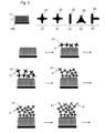
- Fig. 1
- Schematischer Verfahrensablauf der Herstellung einer Schicht aus mehreren Lagen zwei verschiedener Verbindungen A und B auf einer Opferschicht
- Fig. 2
- Rasterelektronenmikroskopaufnahme einer POF-Membran auf einem Kupfernetz nach Ausführungsbeispiel 2.
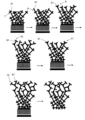
- Fig. 3
- Herstellung von unterschiedlich porösen Schichten innerhalb einer Folie aus mehreren Lagen verschiedener Verbindungen A-E auf einer Opferschicht.
- Fig. 4
- Permeanz (P in Nm3m-2h-1bar-1) von acht verschiedenen Gasen mit Molekülen unterschiedlich großer kinetischer Durchmesser (Ø in Å) durch eine POF Nanomembran, die auf einer PAN/PDMS Stützmembran aufliegt (gefüllte Rauten) im Vergleich zu der PAN/PDMS Stützmembran (gefüllte Dreiecke).
- Fig. 5
- Selektivität (S in Gas x/H2) der POF Nanomembran (gefüllte Rauten) von H2 gegenüber sieben verschiedenen Gasen mit Molekülen unterschiedlich großer kinetischer Durchmesser (Ø in Å).
- In
Fig. 1 ist der Aufbau einer Schicht aus zwei verschiedenen Lagen auf einer Opferschicht schematisch dargestellt. Die Verbindungen X der Opferschicht (1) sind auf einem Substrat (100) aufgebracht und mit funktionellen Gruppen (11) versehen. Die funktionellen Gruppen (11) der Verbindungen X der Opferschicht sind komplementär zu den funktionellen Gruppen (22) der Verbindungen A (21) der ersten Lage (2), welche ebenfalls komplementär zu den funktionellen Gruppen (32) der Verbindungen B (31) der zweiten Lage (3) sind. Auf die Opferschicht (1) wird nun abwechselnd jeweils eine Lage der Verbindungen A (21) der ersten Lage (2) und eine Lage der Verbindungen B (31) der zweiten Lage (3) aufgebracht, bis die gewünschte Dicke der Folie erreicht ist. - Anschließend wird die Opferschicht (1) aufgelöst (12) und man erhält die freistehende POF-Membran (4).
-
Fig. 3 zeigt eine Rasterelektronenmikroskopaufnahme einer freistehenden POF-Membran auf einem Kupfernetz. Die POF-Membran besteht aus 8 Schichten der Verbindungen Tetrakis(4-azidophenyl)-methan) und Tetrakis(4-ethinylphenyl)methan). - In
Fig. 4 ist der Aufbau einer Schicht aus 5 verschiedenen Lagen auf einer Opferschicht schematisch dargestellt. Die Verbindungen X der Opferschicht (1) sind auf einem Substrat (100) aufgebracht und mit funktionellen Gruppen (11) versehen. Die funktionellen Gruppen (11) der Verbindungen X der Opferschicht sind komplementär zu den funktionellen Gruppen (22) der Verbindungen A (21) der ersten Lage (2), welche ebenfalls komplementär zu den funktionellen Gruppen (32) der Verbindungen B (31) der zweiten Lage (3) sind. Auf die Opferschicht (1) wird nun zweimal abwechselnd jeweils eine Lage der Verbindungen A (21) der ersten Lage (2) und eine Lage der Verbindungen B (31) der zweiten Lage (3) aufgebracht, bis die gewünschte Dicke der Folie erreicht ist. Auf die zweite Lage der Verbindung B (31) der zweiten Lage (3) wird als nächstes eine Lage der Verbindung C (51), deren funktionelle Gruppen komplementär zu den funktionellen Gruppen der Verbindung B (31) sind, aufgebracht. Darauf wird eine Lage der Verbindung B (31) aufgebracht und erneut eine Lage der Verbindung C (41). Nun wird als nächstes eine Lage der Verbindung D (51), deren funktionelle Gruppen komplementär zu den funktionellen Gruppen der Verbindung C (41) sind aufgebracht. Darauf wird eine Lage der Verbindung E (61), deren funktionelle Gruppen komplementär zu den funktionellen Gruppen der Verbindung D (51) sind aufgebracht. Anschließend wird eine Lage der Verbindung D (61) aufgebracht und erneut eine Lage der Verbindung E (61). Anschließend wird die Opferschicht (1) aufgelöst und man erhält die freistehende POF-Membran (4). - Es wurde zunächst eine Opferschicht bestehend aus einem N3 funktionalisierten SURMOF hergestellt. Die SURMOF wurden wie in Literatur (M. Tsotsalas et al. J. Am. Chem. Soc. 2014, 136, 8-11) beschrieben synthetisiert. Dabei wurden 10 Lagen SURMOF bestehend aus Kupfer(II)acetat als Metallzentren und 2,2'-diazido-4,4'-stilbenedicarboxylic acid (DA-SBDC) hergestellt. Die N3-Funktionen dienen im layer-by-layer Verfahren (LbL) als Anknüpfungspunkte für die kovalente Anknüpfung der Komponente A (in diesem Beispiel Tetrakis(4-ethinylphenyl)methan) über eine Kupfer-katalysierte Alkin-Azid Kupplung. Im Anschluss wird dann die Komponente B (in diesem Beispiel Tetrakis(4-azidophenyl)-methan)an nicht abreagierte Ethinyl-Funktionen der Komponente A gebunden.
Fig. 1 zeigt die Bausteine A und B und eine schematische Darstellung der LbL Synthese. Vor jedem Schritt wurde ein Kupferkatalysator zugegeben (Tetrakis-acetonitrile-copper(I) hexafluorophosphate). Die Synthese fand unter Schutzgas (N2) statt. Nach jedem Schritt wurde das Substrat ausgiebig mit THF gespült. TPM.-azid, TPM-alkin und Tetrakis(acetonitril)Kupfer(I) hexafluorophosphat wurden in 25 mL wasserfreiem THF (c = 2 mmol/L) gelöst. Die Synthese wurde unter Schutzgas (N2) mittels Schlenktechnik durchgeführt. TPMazid und TPM-alkin wurden jeweils mit Cu(I)Katalysator versetzt und alternierend zum Substrat gegeben.- Nach jedem Schritt wurde das Substrat mit THF gespült. Die Reaktion wurde bei 40 °C für 30 Minuten durchgeführt. - Nach wenigen Minuten einlegen der SURMOF/POF Membran aus Ausführungsbeispiel 1 (2×2 cm) in einer Lösung aus 1 mg EDTA in 10 mL Ethanol/Wasser (1/1 nach Volumen) lässt sich so die POF Schicht isolieren. Die freie POF Membran, kann dann beispielsweise mit einem TEM Netz aufgefischt werden. Die SEM Aufnahmen der aufgefischten Membran ist in
Fig. 2 gezeigt. - Für Gastrennungsanwendungen wurde die freistehende POF Membran auf einen.PAN/PDMS Stützmembran (Yave et al., Nanotechnologie (2019) 395301) übertragen. Anschließend wurden 8 verschiedene Gase (Helium, Wasserstoff, Kohlenstoffdioxid, Argon, Sauerstoff, Stickstoff, Methan und Ethan) auf deren Permeanz getestet. Die Permeanz der Gase wurde bei einem Einspeisungsdruck zwischen 108 und 280 mbar und bei einer Temperatur von 30°C mittels eines konstantes Volumen/variabler Druck experimentellen Aufbau (A. M. Shishatskii et al. Journal of,Membrane Science 1996, 112, 275-285) gemessen.
Tabelle 2: Ergebnisse der Analyse der Permeanz verschiedener Gase durch die POF-Membran Gas Durchmesser (Å) Permeanz (Nm3 m-2h-1bar-1) Helium 2,6 1,72 Wasserstoff 2,89 1,86 Kohlenstoffdioxid 3,3 0,93 Argon 3,42 0,10 Sauerstoff 3,46 0,20 Stickstoff 3, 64 0,06 Methan 3,8 0,08 Ethan 4,43 0,046 -
Fig. 4 zeigt die Permeanz von acht verschiedenen Gasen mit Molekülen unterschiedlich großer kinetischer Durchmesser durch eine POF Nanomembran, aufliegend auf einer PDMS Stützmembran, im Vergleich zu der PDMS Stützmembran. Die Ergebnisse zeigen deutlich dass die Permeanz der verschiedenen Gase durch die POF Membran stark von dem Kinetischen Durchmesser der Gase abhängt (im Gegensatz zur PDMS Stützmembran alleine, bei welcher die Permeanz von den Adsorptions- und Diffusionseigenschaften der Gase durch die Membran abhängt).Fig. 5 zeigt die Selektivität der POF Nanomembran von H2 gegenüber sieben verschiedenen Gasen mit Molekülen unterschiedlich großer kinetischer Durchmesser. Die Ergebnisse zeigen deutlich, dass die erhaltene Membran als Molekularsieb verwendet werden kann. - Es wurde zunächst eine Opferschicht bestehend aus einem N3 funktionalisierten SURMOF hergestellt. Die N3-Funktionen dienen im layer-by-layerVerfahren (LbL) als Anknüpfungspunkte für die kovalente Anknüpfung der Komponente A (siehe Tabelle 3) über eine Kupfer-katalysierte Alkin-Azid Kupplung. Im Anschluss wird dann die Komponente B (Tetrakis(4-azidophenyl)-methan) an nicht abreagierte Ethinyl-Funktionen der Komponente A gebunden. FVor jedem Schritt wurde ein Kupferkatalysator zugegeben (Tetrakis-acetonitrile-copper(I) hexafluorophosphate). Die Synthese fand unter Schutzgas (N2) statt. Nach jedem Schritt wurde das Substrat ausgiebig mit THF gespült.
Tabelle 3: Komponenten A der weiteren POF-Membranen aus Ausführungsbeispiel 3 mit jeweils 16 Lagen. Experiment Komponente A 1 
2 
3 
4 
5 
6 
-
- G. Decher et al. Science 1997, 277, 1232-1237
- Kim et al. Macromolecules, 2011, 44, 7092
- Qian et al. Langmuir, 2012, 28, 17803
- M. Tsotsalas et al. J. Am. Chem. Soc. 2014, 136, 8-11
- A. M. Shishatskii et al. Journal of Membrane Science 1996, 112, 275-285
Claims (10)
- Verfahren zur Herstellung von mikroporösen organischen POF- (Porous Organic Framework) Membranen, enthaltend mindestens zwei verschiedene organische Verbindungen, die aromatische Bausteine enthalten, wobei mindestens eine der organischen Verbindungen mindestens zwei funktionelle Gruppen und mindestens eine der weiteren organischen Verbindungen mindestens drei funktionelle Gruppen aufweist, mit den folgenden Verfahrensschritten:a) Bereitstellen einer Opferschicht mit einer Vielzahl gleicher funktioneller Gruppenb) Aufbringen einer ersten Lage einer ersten organischen Verbindung durch Reaktion mit den funktionellen Gruppen der Opferschichtc) Aufbringen einer ersten Lage einer zweiten organischen Verbindung durch Reaktion mit mindestens einer der funktionellen Gruppen der organischen Verbindungen der ersten Laged) Auflösen der Opferschichte) Entnahme der POF-Membran,wobei mindestens eine der funktionellen Gruppen einer Lage oder der Opferschicht mit mindestens einer der funktionellen Gruppen der nachfolgenden Lage reagiert und die funktionellen Gruppen der aufeinanderfolgenden Lagen komplementär sind und/oder durch Schutzgruppen geschützt sind,wobei mehr als 2 verschiedene organische Verbindungen eingesetzt werden, um mehr als 2 verschiedene Lagen zu erzeugen,wobei die Opferschicht aus einem MOF (Metal-Organic Framework) oder SURMOF (Surface Anchored Metal-Organic Framework) Material besteht,wobei die POF-Membran freistehend ist und eine homogene, kontinuierliche Schichtdicke von mindestens 0,3 nm und eine Porengröße von 0,01 - 2 nm aufweist.
- Verfahren nach Anspruch 1, wobei zwischen den Verfahrensschritten c) und d) folgende Verfahrensschritte erfolgenc i) Aufbringen einer weiteren Lage der ersten oder einer weiteren organischen Verbindung, undc ii) Aufbringen einer weiteren Lage einer weiteren organischen Verbindung mit mindestens zwei funktionellen Gruppen und/oderc iii) Wiederholung der Schritte c, c i und/oder c ii, bis eine gewünschte Schichtdicke erreicht ist.
- Verfahren nach Anspruch 2, wobei nach mindestens einem der Verfahrensschritte a), b), c), d), e) eine Aktivierung der funktionellen Gruppe der jeweils zuletzt aufgebrachten Lage erfolgt.
- Verfahren nach einem der Ansprüche 1 bis 3, wobei die Reaktionen der Verfahrensschritte b-f zu kovalenten Bindungen führen.
- Verfahren nach einem der Ansprüche 1 bis 4, wobei die Reaktionen der Verfahrensschritte b-f ausgewählt sind unter Trimerisierung von Isocyanatgruppen, Kondensation von Alkoholen und Carbonsäurechloriden, Kupplungsreaktionen, nucleophile Substitutionen, Kreuzkupplungsreaktionen, Click-Chemie-Reaktionen.
- Verfahren nach einem der Ansprüche 1 bis 5, wobei Verfahrensschritt e) durch eine Veränderung des pH-Werts oder durch Zugabe eines Komplexbildners erfolgt.
- Mikroporöse organische POF-Membran, hergestellt nach einem Verfahren der Ansprüche 1 bis 6.
- Verwendung der nach einem der Ansprüche 1 bis 6 hergestellten POF-Membran für die Gastrennung, die Wasseraufbereitung und/oder die Nanofiltration.
- Verwendung der nach einem der Ansprüche 1 bis 6 hergestellten POF-Membran in Brennstoffzellen, Batterien und/oder für die chemische Katalyse.
- Verwendung der nach einem der Ansprüche 1 bis 6 hergestellten POF-Membran in organischen Leuchtdioden (OLEDs), organischen Feldeffekttransistoren/Dünnschichttransistoren (OFET) und organischen Solarzellen (OPV).
Applications Claiming Priority (1)
| Application Number | Priority Date | Filing Date | Title |
|---|---|---|---|
| DE102014112088.4A DE102014112088A1 (de) | 2014-08-25 | 2014-08-25 | Verfahren zur Herstellung mikroporöser organischer Membranen, mikroporöse organische Membranen und deren Verwendung |
Publications (2)
| Publication Number | Publication Date |
|---|---|
| EP2992947A1 EP2992947A1 (de) | 2016-03-09 |
| EP2992947B1 true EP2992947B1 (de) | 2023-03-01 |
Family
ID=54065635
Family Applications (1)
| Application Number | Title | Priority Date | Filing Date |
|---|---|---|---|
| EP15002482.6A Active EP2992947B1 (de) | 2014-08-25 | 2015-08-21 | Verfahren zur herstellung mikroporöser organischer membranen, mikroporöse organische membranen und deren verwendung |
Country Status (2)
| Country | Link |
|---|---|
| EP (1) | EP2992947B1 (de) |
| DE (1) | DE102014112088A1 (de) |
Families Citing this family (6)
| Publication number | Priority date | Publication date | Assignee | Title |
|---|---|---|---|---|
| CN106380579B (zh) * | 2016-09-09 | 2019-02-01 | 武汉工程大学 | 一类基于偶氮苯的有机多孔聚合物及其制备方法和应用 |
| US12502354B2 (en) * | 2019-01-24 | 2025-12-23 | Northwestern University | High density lipoprotein mimetic nanoparticles using lipid conjugated core scaffolds |
| CN110247016B (zh) * | 2019-06-10 | 2021-02-02 | 湖北大学 | 一体化三维有序多孔薄膜电极材料及其制备方法、应用 |
| CN115582027B (zh) * | 2022-09-09 | 2024-07-19 | 天津工业大学 | 一种不同长度烷基链修饰的共价有机框架有机溶剂纳滤膜制备方法 |
| CN119684548B (zh) * | 2024-11-15 | 2026-04-28 | 三峡大学 | 一种炔基修饰的酰腙共价有机框架材料,制备方法及其在燃料电池方面的应用 |
| CN121796696A (zh) * | 2026-03-09 | 2026-04-07 | 上海交通大学医学院附属仁济医院 | 一种改性珊瑚人工骨材料及其制备方法与应用 |
Family Cites Families (2)
| Publication number | Priority date | Publication date | Assignee | Title |
|---|---|---|---|---|
| US20090047517A1 (en) * | 2007-06-27 | 2009-02-19 | Francesco Caruso | Multilayer polymer films |
| US8377999B2 (en) * | 2011-07-13 | 2013-02-19 | Xerox Corporation | Porous structured organic film compositions |
-
2014
- 2014-08-25 DE DE102014112088.4A patent/DE102014112088A1/de not_active Ceased
-
2015
- 2015-08-21 EP EP15002482.6A patent/EP2992947B1/de active Active
Also Published As
| Publication number | Publication date |
|---|---|
| DE102014112088A1 (de) | 2016-02-25 |
| EP2992947A1 (de) | 2016-03-09 |
Similar Documents
| Publication | Publication Date | Title |
|---|---|---|
| EP2992947B1 (de) | Verfahren zur herstellung mikroporöser organischer membranen, mikroporöse organische membranen und deren verwendung | |
| Zhang et al. | Supramolecular chemistry assisted construction of ultra-stable solvent-resistant membranes for angstrom-sized molecular separation | |
| Khan et al. | Solid–vapor interface engineered covalent organic framework membranes for molecular separation | |
| Kalaj et al. | MOF-polymer hybrid materials: from simple composites to tailored architectures | |
| DE69534096T2 (de) | Hochpermeable Umkehrosmose-Verbundmembran, Verfahren zu deren Herstellung und Verfahren zu deren Verwendung | |
| Shekhah et al. | The liquid phase epitaxy method for the construction of oriented ZIF-8 thin films with controlled growth on functionalized surfaces | |
| Sun et al. | Covalent organic framework membranes with regulated orientation for monovalent cation sieving | |
| DE102012211300B4 (de) | Anwendung von porösen strukturierten organischen Filmen zur Gasaufnahme | |
| DE112004001096B4 (de) | Polyelektrolyttinte, Verfahren zu deren Herstellung und deren Verwendung zur Herstellung eines Filaments | |
| US8828239B2 (en) | Flexible free-standing ultrathin or thin protein membrane, its fabrication method and application | |
| JP2019150818A (ja) | 半透膜、およびその製造方法 | |
| DE112017004092T5 (de) | Herstellung von stickstoffreichem dreidimensionalem mesoporösem kohlenstoffnitrid und seine abtast- und photokatalytischen eigenschaften | |
| Xing et al. | Metal-organic framework based molecularly imprinted nanofiber membranes with enhanced selective recognition and separation performance: A multiple strengthening system | |
| EP1910586A1 (de) | Hochporöse schichten aus mof-materialien und verfahren zur herstellung derartiger schichten | |
| DE102012211305B4 (de) | Poröser strukturierter organischer Film | |
| EP0094060B1 (de) | Verfahren zur Herstellung von Membranen auf der Basis von Kieselsäureheteropolykondensaten, auf diese Weise herstellbare Membranen sowie deren Verwendung | |
| EP2943269A1 (de) | Verfahren zur herstellung eines kunststoffartikels mit hydrophober pfropfbeschichtung sowie kunststoffartikel | |
| CN111087615B (zh) | 一种cof膜,其制备方法、转移方法、用途和含有其的芯片 | |
| EP1141038B1 (de) | Verfahren zur herstellung eines polymeren netzwerkes | |
| Zhang et al. | Hydrogen bonded layer-by-layer assembly of poly (2-vinylpyridine) and poly (acrylic acid): influence of molecular weight on the formation of microporous film by post-base treatment | |
| Chen et al. | Molecular dissolution behaviors on porous membrane surface using hierarchical metal–organic framework lamellar membrane | |
| DE19916802A1 (de) | Verbundmembran auf Polyanilinbasis | |
| DE102011079778A1 (de) | Membran umfassend mindestens ein photochemisch vernetztes Polyimid | |
| Cichelli et al. | Chiral permselectivity in nanoporous opal films surface-modified with chiral selector moieties | |
| EP1232018A2 (de) | Verfahren zum aufbringen eines polymers auf einen träger |
Legal Events
| Date | Code | Title | Description |
|---|---|---|---|
| PUAI | Public reference made under article 153(3) epc to a published international application that has entered the european phase |
Free format text: ORIGINAL CODE: 0009012 |
|
| AK | Designated contracting states |
Kind code of ref document: A1 Designated state(s): AL AT BE BG CH CY CZ DE DK EE ES FI FR GB GR HR HU IE IS IT LI LT LU LV MC MK MT NL NO PL PT RO RS SE SI SK SM TR |
|
| AX | Request for extension of the european patent |
Extension state: BA ME |
|
| STAA | Information on the status of an ep patent application or granted ep patent |
Free format text: STATUS: REQUEST FOR EXAMINATION WAS MADE |
|
| 17P | Request for examination filed |
Effective date: 20161108 |
|
| RBV | Designated contracting states (corrected) |
Designated state(s): AL AT BE BG CH CY CZ DE DK EE ES FI FR GB GR HR HU IE IS IT LI LT LU LV MC MK MT NL NO PL PT RO RS SE SI SK SM TR |
|
| R17P | Request for examination filed (corrected) |
Effective date: 20161108 |
|
| RBV | Designated contracting states (corrected) |
Designated state(s): AL AT BE BG CH CY CZ DE DK EE ES FI FR GB GR HR HU IE IS IT LI LT LU LV MC MK MT NL NO PL PT RO RS SE SI SK SM TR |
|
| STAA | Information on the status of an ep patent application or granted ep patent |
Free format text: STATUS: EXAMINATION IS IN PROGRESS |
|
| 17Q | First examination report despatched |
Effective date: 20181029 |
|
| GRAP | Despatch of communication of intention to grant a patent |
Free format text: ORIGINAL CODE: EPIDOSNIGR1 |
|
| STAA | Information on the status of an ep patent application or granted ep patent |
Free format text: STATUS: GRANT OF PATENT IS INTENDED |
|
| INTG | Intention to grant announced |
Effective date: 20221007 |
|
| GRAS | Grant fee paid |
Free format text: ORIGINAL CODE: EPIDOSNIGR3 |
|
| GRAA | (expected) grant |
Free format text: ORIGINAL CODE: 0009210 |
|
| STAA | Information on the status of an ep patent application or granted ep patent |
Free format text: STATUS: THE PATENT HAS BEEN GRANTED |
|
| AK | Designated contracting states |
Kind code of ref document: B1 Designated state(s): AL AT BE BG CH CY CZ DE DK EE ES FI FR GB GR HR HU IE IS IT LI LT LU LV MC MK MT NL NO PL PT RO RS SE SI SK SM TR |
|
| REG | Reference to a national code |
Ref country code: GB Ref legal event code: FG4D Free format text: NOT ENGLISH |
|
| REG | Reference to a national code |
Ref country code: CH Ref legal event code: EP Ref country code: AT Ref legal event code: REF Ref document number: 1550600 Country of ref document: AT Kind code of ref document: T Effective date: 20230315 |
|
| REG | Reference to a national code |
Ref country code: DE Ref legal event code: R096 Ref document number: 502015016277 Country of ref document: DE |
|
| REG | Reference to a national code |
Ref country code: IE Ref legal event code: FG4D Free format text: LANGUAGE OF EP DOCUMENT: GERMAN |
|
| REG | Reference to a national code |
Ref country code: LT Ref legal event code: MG9D |
|
| REG | Reference to a national code |
Ref country code: NL Ref legal event code: MP Effective date: 20230301 |
|
| PG25 | Lapsed in a contracting state [announced via postgrant information from national office to epo] |
Ref country code: RS Free format text: LAPSE BECAUSE OF FAILURE TO SUBMIT A TRANSLATION OF THE DESCRIPTION OR TO PAY THE FEE WITHIN THE PRESCRIBED TIME-LIMIT Effective date: 20230301 Ref country code: NO Free format text: LAPSE BECAUSE OF FAILURE TO SUBMIT A TRANSLATION OF THE DESCRIPTION OR TO PAY THE FEE WITHIN THE PRESCRIBED TIME-LIMIT Effective date: 20230601 Ref country code: LV Free format text: LAPSE BECAUSE OF FAILURE TO SUBMIT A TRANSLATION OF THE DESCRIPTION OR TO PAY THE FEE WITHIN THE PRESCRIBED TIME-LIMIT Effective date: 20230301 Ref country code: LT Free format text: LAPSE BECAUSE OF FAILURE TO SUBMIT A TRANSLATION OF THE DESCRIPTION OR TO PAY THE FEE WITHIN THE PRESCRIBED TIME-LIMIT Effective date: 20230301 Ref country code: HR Free format text: LAPSE BECAUSE OF FAILURE TO SUBMIT A TRANSLATION OF THE DESCRIPTION OR TO PAY THE FEE WITHIN THE PRESCRIBED TIME-LIMIT Effective date: 20230301 Ref country code: ES Free format text: LAPSE BECAUSE OF FAILURE TO SUBMIT A TRANSLATION OF THE DESCRIPTION OR TO PAY THE FEE WITHIN THE PRESCRIBED TIME-LIMIT Effective date: 20230301 |
|
| PG25 | Lapsed in a contracting state [announced via postgrant information from national office to epo] |
Ref country code: SE Free format text: LAPSE BECAUSE OF FAILURE TO SUBMIT A TRANSLATION OF THE DESCRIPTION OR TO PAY THE FEE WITHIN THE PRESCRIBED TIME-LIMIT Effective date: 20230301 Ref country code: PL Free format text: LAPSE BECAUSE OF FAILURE TO SUBMIT A TRANSLATION OF THE DESCRIPTION OR TO PAY THE FEE WITHIN THE PRESCRIBED TIME-LIMIT Effective date: 20230301 Ref country code: NL Free format text: LAPSE BECAUSE OF FAILURE TO SUBMIT A TRANSLATION OF THE DESCRIPTION OR TO PAY THE FEE WITHIN THE PRESCRIBED TIME-LIMIT Effective date: 20230301 Ref country code: GR Free format text: LAPSE BECAUSE OF FAILURE TO SUBMIT A TRANSLATION OF THE DESCRIPTION OR TO PAY THE FEE WITHIN THE PRESCRIBED TIME-LIMIT Effective date: 20230602 Ref country code: FI Free format text: LAPSE BECAUSE OF FAILURE TO SUBMIT A TRANSLATION OF THE DESCRIPTION OR TO PAY THE FEE WITHIN THE PRESCRIBED TIME-LIMIT Effective date: 20230301 |
|
| PG25 | Lapsed in a contracting state [announced via postgrant information from national office to epo] |
Ref country code: SM Free format text: LAPSE BECAUSE OF FAILURE TO SUBMIT A TRANSLATION OF THE DESCRIPTION OR TO PAY THE FEE WITHIN THE PRESCRIBED TIME-LIMIT Effective date: 20230301 Ref country code: RO Free format text: LAPSE BECAUSE OF FAILURE TO SUBMIT A TRANSLATION OF THE DESCRIPTION OR TO PAY THE FEE WITHIN THE PRESCRIBED TIME-LIMIT Effective date: 20230301 Ref country code: PT Free format text: LAPSE BECAUSE OF FAILURE TO SUBMIT A TRANSLATION OF THE DESCRIPTION OR TO PAY THE FEE WITHIN THE PRESCRIBED TIME-LIMIT Effective date: 20230703 Ref country code: EE Free format text: LAPSE BECAUSE OF FAILURE TO SUBMIT A TRANSLATION OF THE DESCRIPTION OR TO PAY THE FEE WITHIN THE PRESCRIBED TIME-LIMIT Effective date: 20230301 Ref country code: CZ Free format text: LAPSE BECAUSE OF FAILURE TO SUBMIT A TRANSLATION OF THE DESCRIPTION OR TO PAY THE FEE WITHIN THE PRESCRIBED TIME-LIMIT Effective date: 20230301 |
|
| PG25 | Lapsed in a contracting state [announced via postgrant information from national office to epo] |
Ref country code: SK Free format text: LAPSE BECAUSE OF FAILURE TO SUBMIT A TRANSLATION OF THE DESCRIPTION OR TO PAY THE FEE WITHIN THE PRESCRIBED TIME-LIMIT Effective date: 20230301 Ref country code: IS Free format text: LAPSE BECAUSE OF FAILURE TO SUBMIT A TRANSLATION OF THE DESCRIPTION OR TO PAY THE FEE WITHIN THE PRESCRIBED TIME-LIMIT Effective date: 20230701 |
|
| REG | Reference to a national code |
Ref country code: DE Ref legal event code: R097 Ref document number: 502015016277 Country of ref document: DE |
|
| PLBE | No opposition filed within time limit |
Free format text: ORIGINAL CODE: 0009261 |
|
| STAA | Information on the status of an ep patent application or granted ep patent |
Free format text: STATUS: NO OPPOSITION FILED WITHIN TIME LIMIT |
|
| PG25 | Lapsed in a contracting state [announced via postgrant information from national office to epo] |
Ref country code: SI Free format text: LAPSE BECAUSE OF FAILURE TO SUBMIT A TRANSLATION OF THE DESCRIPTION OR TO PAY THE FEE WITHIN THE PRESCRIBED TIME-LIMIT Effective date: 20230301 Ref country code: DK Free format text: LAPSE BECAUSE OF FAILURE TO SUBMIT A TRANSLATION OF THE DESCRIPTION OR TO PAY THE FEE WITHIN THE PRESCRIBED TIME-LIMIT Effective date: 20230301 |
|
| 26N | No opposition filed |
Effective date: 20231204 |
|
| PG25 | Lapsed in a contracting state [announced via postgrant information from national office to epo] |
Ref country code: MC Free format text: LAPSE BECAUSE OF FAILURE TO SUBMIT A TRANSLATION OF THE DESCRIPTION OR TO PAY THE FEE WITHIN THE PRESCRIBED TIME-LIMIT Effective date: 20230301 |
|
| REG | Reference to a national code |
Ref country code: CH Ref legal event code: PL |
|
| PG25 | Lapsed in a contracting state [announced via postgrant information from national office to epo] |
Ref country code: MC Free format text: LAPSE BECAUSE OF FAILURE TO SUBMIT A TRANSLATION OF THE DESCRIPTION OR TO PAY THE FEE WITHIN THE PRESCRIBED TIME-LIMIT Effective date: 20230301 |
|
| PG25 | Lapsed in a contracting state [announced via postgrant information from national office to epo] |
Ref country code: LU Free format text: LAPSE BECAUSE OF NON-PAYMENT OF DUE FEES Effective date: 20230821 |
|
| PG25 | Lapsed in a contracting state [announced via postgrant information from national office to epo] |
Ref country code: LU Free format text: LAPSE BECAUSE OF NON-PAYMENT OF DUE FEES Effective date: 20230821 Ref country code: CH Free format text: LAPSE BECAUSE OF NON-PAYMENT OF DUE FEES Effective date: 20230831 |
|
| REG | Reference to a national code |
Ref country code: BE Ref legal event code: MM Effective date: 20230831 |
|
| REG | Reference to a national code |
Ref country code: IE Ref legal event code: MM4A |
|
| PG25 | Lapsed in a contracting state [announced via postgrant information from national office to epo] |
Ref country code: IT Free format text: LAPSE BECAUSE OF FAILURE TO SUBMIT A TRANSLATION OF THE DESCRIPTION OR TO PAY THE FEE WITHIN THE PRESCRIBED TIME-LIMIT Effective date: 20230301 |
|
| PG25 | Lapsed in a contracting state [announced via postgrant information from national office to epo] |
Ref country code: IE Free format text: LAPSE BECAUSE OF NON-PAYMENT OF DUE FEES Effective date: 20230821 |
|
| PG25 | Lapsed in a contracting state [announced via postgrant information from national office to epo] |
Ref country code: IE Free format text: LAPSE BECAUSE OF NON-PAYMENT OF DUE FEES Effective date: 20230821 |
|
| PG25 | Lapsed in a contracting state [announced via postgrant information from national office to epo] |
Ref country code: BE Free format text: LAPSE BECAUSE OF NON-PAYMENT OF DUE FEES Effective date: 20230831 |
|
| REG | Reference to a national code |
Ref country code: AT Ref legal event code: MM01 Ref document number: 1550600 Country of ref document: AT Kind code of ref document: T Effective date: 20230821 |
|
| PG25 | Lapsed in a contracting state [announced via postgrant information from national office to epo] |
Ref country code: AT Free format text: LAPSE BECAUSE OF NON-PAYMENT OF DUE FEES Effective date: 20230821 |
|
| PG25 | Lapsed in a contracting state [announced via postgrant information from national office to epo] |
Ref country code: AT Free format text: LAPSE BECAUSE OF NON-PAYMENT OF DUE FEES Effective date: 20230821 |
|
| PG25 | Lapsed in a contracting state [announced via postgrant information from national office to epo] |
Ref country code: BG Free format text: LAPSE BECAUSE OF FAILURE TO SUBMIT A TRANSLATION OF THE DESCRIPTION OR TO PAY THE FEE WITHIN THE PRESCRIBED TIME-LIMIT Effective date: 20230301 |
|
| PG25 | Lapsed in a contracting state [announced via postgrant information from national office to epo] |
Ref country code: BG Free format text: LAPSE BECAUSE OF FAILURE TO SUBMIT A TRANSLATION OF THE DESCRIPTION OR TO PAY THE FEE WITHIN THE PRESCRIBED TIME-LIMIT Effective date: 20230301 |
|
| PG25 | Lapsed in a contracting state [announced via postgrant information from national office to epo] |
Ref country code: CY Free format text: LAPSE BECAUSE OF FAILURE TO SUBMIT A TRANSLATION OF THE DESCRIPTION OR TO PAY THE FEE WITHIN THE PRESCRIBED TIME-LIMIT; INVALID AB INITIO Effective date: 20150821 |
|
| PG25 | Lapsed in a contracting state [announced via postgrant information from national office to epo] |
Ref country code: HU Free format text: LAPSE BECAUSE OF FAILURE TO SUBMIT A TRANSLATION OF THE DESCRIPTION OR TO PAY THE FEE WITHIN THE PRESCRIBED TIME-LIMIT; INVALID AB INITIO Effective date: 20150821 |
|
| PGFP | Annual fee paid to national office [announced via postgrant information from national office to epo] |
Ref country code: DE Payment date: 20250819 Year of fee payment: 11 |
|
| PGFP | Annual fee paid to national office [announced via postgrant information from national office to epo] |
Ref country code: GB Payment date: 20250822 Year of fee payment: 11 |
|
| PGFP | Annual fee paid to national office [announced via postgrant information from national office to epo] |
Ref country code: FR Payment date: 20250821 Year of fee payment: 11 |
|
| PG25 | Lapsed in a contracting state [announced via postgrant information from national office to epo] |
Ref country code: TR Free format text: LAPSE BECAUSE OF FAILURE TO SUBMIT A TRANSLATION OF THE DESCRIPTION OR TO PAY THE FEE WITHIN THE PRESCRIBED TIME-LIMIT Effective date: 20230301 |