EP2991707B1 - Flusswegbaugruppe - Google Patents
Flusswegbaugruppe Download PDFInfo
- Publication number
- EP2991707B1 EP2991707B1 EP14791686.0A EP14791686A EP2991707B1 EP 2991707 B1 EP2991707 B1 EP 2991707B1 EP 14791686 A EP14791686 A EP 14791686A EP 2991707 B1 EP2991707 B1 EP 2991707B1
- Authority
- EP
- European Patent Office
- Prior art keywords
- subassembly
- needle
- valve
- fluid path
- cover
- Prior art date
- Legal status (The legal status is an assumption and is not a legal conclusion. Google has not performed a legal analysis and makes no representation as to the accuracy of the status listed.)
- Active
Links
- 230000037361 pathway Effects 0.000 title claims description 14
- 239000012530 fluid Substances 0.000 claims description 49
- 239000003814 drug Substances 0.000 claims description 27
- 230000033001 locomotion Effects 0.000 claims description 25
- 238000000034 method Methods 0.000 claims description 10
- 238000012377 drug delivery Methods 0.000 claims description 7
- 230000005484 gravity Effects 0.000 claims description 7
- 238000011049 filling Methods 0.000 claims description 5
- 238000004806 packaging method and process Methods 0.000 claims description 3
- 230000036512 infertility Effects 0.000 claims description 2
- 230000001954 sterilising effect Effects 0.000 claims description 2
- 230000004913 activation Effects 0.000 description 69
- 230000007246 mechanism Effects 0.000 description 20
- 239000000853 adhesive Substances 0.000 description 11
- 230000001070 adhesive effect Effects 0.000 description 11
- 230000036961 partial effect Effects 0.000 description 11
- 238000006073 displacement reaction Methods 0.000 description 9
- 238000001802 infusion Methods 0.000 description 6
- 230000003993 interaction Effects 0.000 description 6
- 238000007689 inspection Methods 0.000 description 5
- 238000009434 installation Methods 0.000 description 5
- 239000004033 plastic Substances 0.000 description 5
- 229920003023 plastic Polymers 0.000 description 5
- 230000008901 benefit Effects 0.000 description 4
- 238000003780 insertion Methods 0.000 description 4
- 230000037431 insertion Effects 0.000 description 4
- 238000000465 moulding Methods 0.000 description 4
- 230000008569 process Effects 0.000 description 4
- 230000000903 blocking effect Effects 0.000 description 3
- 229910052751 metal Inorganic materials 0.000 description 3
- 239000002184 metal Substances 0.000 description 3
- 238000012545 processing Methods 0.000 description 3
- 230000000712 assembly Effects 0.000 description 2
- 238000000429 assembly Methods 0.000 description 2
- 230000008859 change Effects 0.000 description 2
- 238000010276 construction Methods 0.000 description 2
- 230000000977 initiatory effect Effects 0.000 description 2
- 238000002347 injection Methods 0.000 description 2
- 239000007924 injection Substances 0.000 description 2
- 239000000463 material Substances 0.000 description 2
- 238000007789 sealing Methods 0.000 description 2
- 238000007920 subcutaneous administration Methods 0.000 description 2
- 238000012371 Aseptic Filling Methods 0.000 description 1
- 230000003213 activating effect Effects 0.000 description 1
- 229910052782 aluminium Inorganic materials 0.000 description 1
- XAGFODPZIPBFFR-UHFFFAOYSA-N aluminium Chemical compound [Al] XAGFODPZIPBFFR-UHFFFAOYSA-N 0.000 description 1
- 238000000418 atomic force spectrum Methods 0.000 description 1
- 230000004323 axial length Effects 0.000 description 1
- 238000005452 bending Methods 0.000 description 1
- 239000003086 colorant Substances 0.000 description 1
- 230000000994 depressogenic effect Effects 0.000 description 1
- 229940079593 drug Drugs 0.000 description 1
- 230000000694 effects Effects 0.000 description 1
- -1 for example Inorganic materials 0.000 description 1
- 230000036541 health Effects 0.000 description 1
- 230000000670 limiting effect Effects 0.000 description 1
- 238000012423 maintenance Methods 0.000 description 1
- 238000004519 manufacturing process Methods 0.000 description 1
- 230000013011 mating Effects 0.000 description 1
- 238000007911 parenteral administration Methods 0.000 description 1
- 230000037368 penetrate the skin Effects 0.000 description 1
- 230000035515 penetration Effects 0.000 description 1
- 230000002829 reductive effect Effects 0.000 description 1
- 230000000284 resting effect Effects 0.000 description 1
- 230000000717 retained effect Effects 0.000 description 1
- 230000000087 stabilizing effect Effects 0.000 description 1
- 229910000811 surgical stainless steel Inorganic materials 0.000 description 1
- 239000010966 surgical stainless steel Substances 0.000 description 1
Images


Classifications
-
- A—HUMAN NECESSITIES
- A61—MEDICAL OR VETERINARY SCIENCE; HYGIENE
- A61M—DEVICES FOR INTRODUCING MEDIA INTO, OR ONTO, THE BODY; DEVICES FOR TRANSDUCING BODY MEDIA OR FOR TAKING MEDIA FROM THE BODY; DEVICES FOR PRODUCING OR ENDING SLEEP OR STUPOR
- A61M5/00—Devices for bringing media into the body in a subcutaneous, intra-vascular or intramuscular way; Accessories therefor, e.g. filling or cleaning devices, arm-rests
- A61M5/14—Infusion devices, e.g. infusing by gravity; Blood infusion; Accessories therefor
- A61M5/142—Pressure infusion, e.g. using pumps
- A61M5/145—Pressure infusion, e.g. using pumps using pressurised reservoirs, e.g. pressurised by means of pistons
- A61M5/1452—Pressure infusion, e.g. using pumps using pressurised reservoirs, e.g. pressurised by means of pistons pressurised by means of pistons
- A61M5/1454—Pressure infusion, e.g. using pumps using pressurised reservoirs, e.g. pressurised by means of pistons pressurised by means of pistons spring-actuated, e.g. by a clockwork
-
- A—HUMAN NECESSITIES
- A61—MEDICAL OR VETERINARY SCIENCE; HYGIENE
- A61M—DEVICES FOR INTRODUCING MEDIA INTO, OR ONTO, THE BODY; DEVICES FOR TRANSDUCING BODY MEDIA OR FOR TAKING MEDIA FROM THE BODY; DEVICES FOR PRODUCING OR ENDING SLEEP OR STUPOR
- A61M5/00—Devices for bringing media into the body in a subcutaneous, intra-vascular or intramuscular way; Accessories therefor, e.g. filling or cleaning devices, arm-rests
- A61M5/14—Infusion devices, e.g. infusing by gravity; Blood infusion; Accessories therefor
- A61M5/1413—Modular systems comprising interconnecting elements
-
- A—HUMAN NECESSITIES
- A61—MEDICAL OR VETERINARY SCIENCE; HYGIENE
- A61M—DEVICES FOR INTRODUCING MEDIA INTO, OR ONTO, THE BODY; DEVICES FOR TRANSDUCING BODY MEDIA OR FOR TAKING MEDIA FROM THE BODY; DEVICES FOR PRODUCING OR ENDING SLEEP OR STUPOR
- A61M5/00—Devices for bringing media into the body in a subcutaneous, intra-vascular or intramuscular way; Accessories therefor, e.g. filling or cleaning devices, arm-rests
- A61M5/14—Infusion devices, e.g. infusing by gravity; Blood infusion; Accessories therefor
- A61M5/142—Pressure infusion, e.g. using pumps
- A61M5/14244—Pressure infusion, e.g. using pumps adapted to be carried by the patient, e.g. portable on the body
- A61M5/14248—Pressure infusion, e.g. using pumps adapted to be carried by the patient, e.g. portable on the body of the skin patch type
-
- A—HUMAN NECESSITIES
- A61—MEDICAL OR VETERINARY SCIENCE; HYGIENE
- A61M—DEVICES FOR INTRODUCING MEDIA INTO, OR ONTO, THE BODY; DEVICES FOR TRANSDUCING BODY MEDIA OR FOR TAKING MEDIA FROM THE BODY; DEVICES FOR PRODUCING OR ENDING SLEEP OR STUPOR
- A61M5/00—Devices for bringing media into the body in a subcutaneous, intra-vascular or intramuscular way; Accessories therefor, e.g. filling or cleaning devices, arm-rests
- A61M5/14—Infusion devices, e.g. infusing by gravity; Blood infusion; Accessories therefor
- A61M5/142—Pressure infusion, e.g. using pumps
- A61M5/145—Pressure infusion, e.g. using pumps using pressurised reservoirs, e.g. pressurised by means of pistons
-
- A—HUMAN NECESSITIES
- A61—MEDICAL OR VETERINARY SCIENCE; HYGIENE
- A61M—DEVICES FOR INTRODUCING MEDIA INTO, OR ONTO, THE BODY; DEVICES FOR TRANSDUCING BODY MEDIA OR FOR TAKING MEDIA FROM THE BODY; DEVICES FOR PRODUCING OR ENDING SLEEP OR STUPOR
- A61M5/00—Devices for bringing media into the body in a subcutaneous, intra-vascular or intramuscular way; Accessories therefor, e.g. filling or cleaning devices, arm-rests
- A61M5/14—Infusion devices, e.g. infusing by gravity; Blood infusion; Accessories therefor
- A61M5/162—Needle sets, i.e. connections by puncture between reservoir and tube ; Connections between reservoir and tube
- A61M5/1626—Needle protectors therefor
-
- A—HUMAN NECESSITIES
- A61—MEDICAL OR VETERINARY SCIENCE; HYGIENE
- A61M—DEVICES FOR INTRODUCING MEDIA INTO, OR ONTO, THE BODY; DEVICES FOR TRANSDUCING BODY MEDIA OR FOR TAKING MEDIA FROM THE BODY; DEVICES FOR PRODUCING OR ENDING SLEEP OR STUPOR
- A61M5/00—Devices for bringing media into the body in a subcutaneous, intra-vascular or intramuscular way; Accessories therefor, e.g. filling or cleaning devices, arm-rests
- A61M5/14—Infusion devices, e.g. infusing by gravity; Blood infusion; Accessories therefor
- A61M5/168—Means for controlling media flow to the body or for metering media to the body, e.g. drip meters, counters ; Monitoring media flow to the body
- A61M5/16804—Flow controllers
- A61M5/16813—Flow controllers by controlling the degree of opening of the flow line
-
- A—HUMAN NECESSITIES
- A61—MEDICAL OR VETERINARY SCIENCE; HYGIENE
- A61M—DEVICES FOR INTRODUCING MEDIA INTO, OR ONTO, THE BODY; DEVICES FOR TRANSDUCING BODY MEDIA OR FOR TAKING MEDIA FROM THE BODY; DEVICES FOR PRODUCING OR ENDING SLEEP OR STUPOR
- A61M5/00—Devices for bringing media into the body in a subcutaneous, intra-vascular or intramuscular way; Accessories therefor, e.g. filling or cleaning devices, arm-rests
- A61M5/178—Syringes
- A61M5/31—Details
- A61M5/3129—Syringe barrels
- A61M5/3134—Syringe barrels characterised by constructional features of the distal end, i.e. end closest to the tip of the needle cannula
-
- A—HUMAN NECESSITIES
- A61—MEDICAL OR VETERINARY SCIENCE; HYGIENE
- A61M—DEVICES FOR INTRODUCING MEDIA INTO, OR ONTO, THE BODY; DEVICES FOR TRANSDUCING BODY MEDIA OR FOR TAKING MEDIA FROM THE BODY; DEVICES FOR PRODUCING OR ENDING SLEEP OR STUPOR
- A61M5/00—Devices for bringing media into the body in a subcutaneous, intra-vascular or intramuscular way; Accessories therefor, e.g. filling or cleaning devices, arm-rests
- A61M5/178—Syringes
- A61M5/31—Details
- A61M5/315—Pistons; Piston-rods; Guiding, blocking or restricting the movement of the rod or piston; Appliances on the rod for facilitating dosing ; Dosing mechanisms
- A61M5/31565—Administration mechanisms, i.e. constructional features, modes of administering a dose
- A61M5/31566—Means improving security or handling thereof
- A61M5/31571—Means preventing accidental administration
-
- B—PERFORMING OPERATIONS; TRANSPORTING
- B65—CONVEYING; PACKING; STORING; HANDLING THIN OR FILAMENTARY MATERIAL
- B65B—MACHINES, APPARATUS OR DEVICES FOR, OR METHODS OF, PACKAGING ARTICLES OR MATERIALS; UNPACKING
- B65B55/00—Preserving, protecting or purifying packages or package contents in association with packaging
- B65B55/02—Sterilising, e.g. of complete packages
- B65B55/04—Sterilising wrappers or receptacles prior to, or during, packaging
-
- A—HUMAN NECESSITIES
- A61—MEDICAL OR VETERINARY SCIENCE; HYGIENE
- A61M—DEVICES FOR INTRODUCING MEDIA INTO, OR ONTO, THE BODY; DEVICES FOR TRANSDUCING BODY MEDIA OR FOR TAKING MEDIA FROM THE BODY; DEVICES FOR PRODUCING OR ENDING SLEEP OR STUPOR
- A61M5/00—Devices for bringing media into the body in a subcutaneous, intra-vascular or intramuscular way; Accessories therefor, e.g. filling or cleaning devices, arm-rests
- A61M5/14—Infusion devices, e.g. infusing by gravity; Blood infusion; Accessories therefor
- A61M5/142—Pressure infusion, e.g. using pumps
- A61M5/14244—Pressure infusion, e.g. using pumps adapted to be carried by the patient, e.g. portable on the body
- A61M5/14248—Pressure infusion, e.g. using pumps adapted to be carried by the patient, e.g. portable on the body of the skin patch type
- A61M2005/14252—Pressure infusion, e.g. using pumps adapted to be carried by the patient, e.g. portable on the body of the skin patch type with needle insertion means
- A61M2005/14256—Pressure infusion, e.g. using pumps adapted to be carried by the patient, e.g. portable on the body of the skin patch type with needle insertion means with means for preventing access to the needle after use
-
- A—HUMAN NECESSITIES
- A61—MEDICAL OR VETERINARY SCIENCE; HYGIENE
- A61M—DEVICES FOR INTRODUCING MEDIA INTO, OR ONTO, THE BODY; DEVICES FOR TRANSDUCING BODY MEDIA OR FOR TAKING MEDIA FROM THE BODY; DEVICES FOR PRODUCING OR ENDING SLEEP OR STUPOR
- A61M5/00—Devices for bringing media into the body in a subcutaneous, intra-vascular or intramuscular way; Accessories therefor, e.g. filling or cleaning devices, arm-rests
- A61M5/178—Syringes
- A61M5/20—Automatic syringes, e.g. with automatically actuated piston rod, with automatic needle injection, filling automatically
- A61M2005/2073—Automatic syringes, e.g. with automatically actuated piston rod, with automatic needle injection, filling automatically preventing premature release, e.g. by making use of a safety lock
-
- A—HUMAN NECESSITIES
- A61—MEDICAL OR VETERINARY SCIENCE; HYGIENE
- A61M—DEVICES FOR INTRODUCING MEDIA INTO, OR ONTO, THE BODY; DEVICES FOR TRANSDUCING BODY MEDIA OR FOR TAKING MEDIA FROM THE BODY; DEVICES FOR PRODUCING OR ENDING SLEEP OR STUPOR
- A61M5/00—Devices for bringing media into the body in a subcutaneous, intra-vascular or intramuscular way; Accessories therefor, e.g. filling or cleaning devices, arm-rests
- A61M5/178—Syringes
- A61M5/24—Ampoule syringes, i.e. syringes with needle for use in combination with replaceable ampoules or carpules, e.g. automatic
- A61M5/2455—Ampoule syringes, i.e. syringes with needle for use in combination with replaceable ampoules or carpules, e.g. automatic with sealing means to be broken or opened
- A61M5/2466—Ampoule syringes, i.e. syringes with needle for use in combination with replaceable ampoules or carpules, e.g. automatic with sealing means to be broken or opened by piercing without internal pressure increase
- A61M2005/2474—Ampoule syringes, i.e. syringes with needle for use in combination with replaceable ampoules or carpules, e.g. automatic with sealing means to be broken or opened by piercing without internal pressure increase with movable piercing means, e.g. ampoule remains fixed or steady
-
- A—HUMAN NECESSITIES
- A61—MEDICAL OR VETERINARY SCIENCE; HYGIENE
- A61M—DEVICES FOR INTRODUCING MEDIA INTO, OR ONTO, THE BODY; DEVICES FOR TRANSDUCING BODY MEDIA OR FOR TAKING MEDIA FROM THE BODY; DEVICES FOR PRODUCING OR ENDING SLEEP OR STUPOR
- A61M2205/00—General characteristics of the apparatus
- A61M2205/19—Constructional features of carpules, syringes or blisters
- A61M2205/192—Avoiding coring, e.g. preventing formation of particles during puncture
- A61M2205/195—Avoiding coring, e.g. preventing formation of particles during puncture by the needle tip shape
-
- A—HUMAN NECESSITIES
- A61—MEDICAL OR VETERINARY SCIENCE; HYGIENE
- A61M—DEVICES FOR INTRODUCING MEDIA INTO, OR ONTO, THE BODY; DEVICES FOR TRANSDUCING BODY MEDIA OR FOR TAKING MEDIA FROM THE BODY; DEVICES FOR PRODUCING OR ENDING SLEEP OR STUPOR
- A61M2205/00—General characteristics of the apparatus
- A61M2205/70—General characteristics of the apparatus with testing or calibration facilities
-
- A—HUMAN NECESSITIES
- A61—MEDICAL OR VETERINARY SCIENCE; HYGIENE
- A61M—DEVICES FOR INTRODUCING MEDIA INTO, OR ONTO, THE BODY; DEVICES FOR TRANSDUCING BODY MEDIA OR FOR TAKING MEDIA FROM THE BODY; DEVICES FOR PRODUCING OR ENDING SLEEP OR STUPOR
- A61M2207/00—Methods of manufacture, assembly or production
-
- A—HUMAN NECESSITIES
- A61—MEDICAL OR VETERINARY SCIENCE; HYGIENE
- A61M—DEVICES FOR INTRODUCING MEDIA INTO, OR ONTO, THE BODY; DEVICES FOR TRANSDUCING BODY MEDIA OR FOR TAKING MEDIA FROM THE BODY; DEVICES FOR PRODUCING OR ENDING SLEEP OR STUPOR
- A61M39/00—Tubes, tube connectors, tube couplings, valves, access sites or the like, specially adapted for medical use
- A61M39/20—Closure caps or plugs for connectors or open ends of tubes
-
- A—HUMAN NECESSITIES
- A61—MEDICAL OR VETERINARY SCIENCE; HYGIENE
- A61M—DEVICES FOR INTRODUCING MEDIA INTO, OR ONTO, THE BODY; DEVICES FOR TRANSDUCING BODY MEDIA OR FOR TAKING MEDIA FROM THE BODY; DEVICES FOR PRODUCING OR ENDING SLEEP OR STUPOR
- A61M39/00—Tubes, tube connectors, tube couplings, valves, access sites or the like, specially adapted for medical use
- A61M39/22—Valves or arrangement of valves
-
- A—HUMAN NECESSITIES
- A61—MEDICAL OR VETERINARY SCIENCE; HYGIENE
- A61M—DEVICES FOR INTRODUCING MEDIA INTO, OR ONTO, THE BODY; DEVICES FOR TRANSDUCING BODY MEDIA OR FOR TAKING MEDIA FROM THE BODY; DEVICES FOR PRODUCING OR ENDING SLEEP OR STUPOR
- A61M5/00—Devices for bringing media into the body in a subcutaneous, intra-vascular or intramuscular way; Accessories therefor, e.g. filling or cleaning devices, arm-rests
- A61M5/14—Infusion devices, e.g. infusing by gravity; Blood infusion; Accessories therefor
- A61M5/162—Needle sets, i.e. connections by puncture between reservoir and tube ; Connections between reservoir and tube
Definitions
- the present invention relates to a drug delivery device for parenteral administration of a medicament.
- Drug delivery devices in the form of infusers are known in the prior art for administering medicament to a patient.
- Infusers are intended for mounting onto a patient's skin for self-administration of a medicament.
- Activation of the infuser not only provides for injection of a needle into a patient's skin, but also to cause auto-drive of a plunger to drive medicament into the patient via the injected needle.
- Typical infuser constructions have the needle fixed to the reservoir.
- U.S. Patent No. 5,858,001 to Tsals et al. an infuser is disclosed that is activated through swivel displacement of a reservoir-containing body.
- a needle that is also caused to penetrate the skin of a patient with the swivel displacement of the body is attached to the Tsals et al. device.
- the needle is fixed to the body to move therewith.
- Other types of infusers are known, including those which use standard needle-mounted syringe barrels. With many infusers, the ability to control the insertion of the needle independent of the administration of medicament is limited.
- PCT Publication WO 2011/146166 discloses an infuser in which activation of an actuator causes a spring to move a stopper in a reservoir from a first position toward a second position, and also causes a needle driver to displace a patient needle from a first state toward a second state. The needle moves relative to the reservoir, and separately from the stopper.
- a flow pathway subassembly including medicament flow pathway components of a medical device, and a holder configured for holding the components so that a center of gravity of the subassembly is disposed substantially on a central longitudinal axis of the subassembly.
- a method of assembling a drug delivery device including assembling a flow path subassembly, packaging and sterilizing the flow path subassembly, aseptically filling the flow path subassembly, inspecting the filled flow path subassembly, and assembling the filled flow path subassembly into a device body.
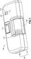
- Fig. 1 is a top perspective view of an infusion device or infuser 100 for infusing a medicament into a patient.
- a user other than a medicament recipient (for example, a health care professional) can use the device 100, for brevity, the term "user” will be employed hereinafter to refer to a patient or other user.
- the device 100 has a top cover 102 and a bottom cover 104 that, together, form a main body 106.
- the device 100 also includes a reservoir or syringe barrel 108, a button 110, and a status viewport 112. Through the status view port 112, as will be subsequently described in greater detail, a user can view the progress of the infusion of the medicament.
- the device 100 can function in three stages: a pre-activated stage (ready for activation), a first activation stage, and an end-of-dose or second activation stage.
- an indicator is visible through the viewport 112 to indicate each of these three stages.
- three colors can be used to represent the three stages.
- three numbers, three symbols, three letters, or three words or phrases can be visible through the viewport 112 to represent the three stages.
- a portion 113 of the viewport 112 is slanted. This reflects light into the viewport 112 and aids the user in viewing the status of the device 100.
- Fig. 2 is a bottom perspective view of the device 100, which includes a removable needle cover 114.
- the needle cover 114 is manufactured in a two-shot molding process.
- the tab 116 of the needle cover 114 preferably folds substantially parallel to and against the bottom of the device 200, on which there is an adhesive 118 for attaching the device to a patient's skin.
- the adhesive 118 is an adhesive pad secured on one side to the bottom cover 104, and having a patient adhesive on the opposing side.
- a removable adhesive liner preferably protects the patient adhesive, and is removed prior to securing the device to the patient's skin.
- the bottom cover 104 also includes one or more access slots 119, through which an assembler can, for example, access the button 110 and/or the needle cover 114 during assembly of the device 100.
- Fig. 3 is a perspective view illustrating the relationship between the button 110 and the needle cover 114 in the pre-activated stage.
- the needle cover 114 includes a safety extension 120 that extends through the bottom cover 104 and engages an engagement hole 122 of the button 110. This engagement prevents the button 110 from moving and activating the device 100 prior to removal of the needle cover 114.
- the safety extension 120 and the needle cover 114 are integrally formed as a unitary construction.
- the safety extension 120 is originally formed as a separate element, and subsequently joined to the needle cover 114, for example, by snapping the safety extension into a recess in the needle cover 114, or using an adhesive.
- the user unfolds the tab 116 about a hinge 117 (for example, a living hinge 117) to extend substantially perpendicular to the bottom cover 104, and then pulls the needle cover 114 out of the device 100, thereby uncovering a hollow patient needle 124 and permitting movement of the button 110.
- the user removes the release liner and then removes the needle shield 114, thereby freeing the button 110 for movement, as subsequently described in greater detail.
- the user removes the release liner from the adhesive 118 subsequent to removing the needle cover 114, or they are removed in a combined fashion.
- the release liner and the needle cover 114 are connected, and the release liner is retained on the needle cover 114 after removal from the infusion device. Such an embodiment allows the user to easily recycle or dispose of the connected release liner and needle cover 114. Examples of ways to connect a release liner and a needle cover can be found in the commonly-owned international application published as WO 2011/075101 , the disclosure of which is incorporated herein in its entirety.
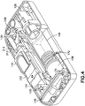
- Fig. 4 is a top perspective view of the device 100 in the pre-activated stage with the top cover 102 removed.
- the device 100 includes a valve cover 126, a rocker 128, a needle arm 130, a lever 132 that rotates about a pivot 134, a shutter 136, and a frame 138 that houses the shutter 136 and guides its movement.
- the shutter 136 is disposed at a first end of the main body 106 and the rocker 128 is disposed at a second end of the main body 106.
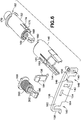
- Figs. 5-9 illustrate several components of a power pack 1380 of the device 100 in the pre-activated stage.
- Fig. 5 is a partial perspective view illustrating the interaction of several components with the shutter 136 in the pre-activated stage.
- the shutter 136 is illustrated as being transparent in Fig. 5 , although one skilled in the art will appreciate that the shutter's opacity can vary without departing from the present invention's scope.
- Fig. 6 is an exploded perspective view of the components illustrated in Fig. 5 .
- Fig. 7 illustrates a barrel plunger 152
- Fig. 8 illustrates an outer-telescoping member 146
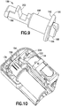
- Fig. 9 illustrates a needle actuation plunger 166.
- the power pack 1380 also includes the frame 138.
- the shutter 136 includes a substantially U-shaped arm cutout 140 and a through arm slot 142 to slidingly accommodate sliding arms 144 of the outer telescoping member 146.
- the shutter 136 also has a barrel plunger cutout 148 with a notch 149 at a top thereof, and a barrel plunger engaging surface 150 to engage the barrel plunger 152, as subsequently described in greater detail.
- the shutter 136 additionally has a horizontally oriented latch slot 154 for selectively engaging the shutter latch 156.
- the barrel plunger 152 is disposed within the outer telescoping member 146 and engages the barrel plunger engaging surface 150 of the shutter 136 at a barrel shutter-engaging structure 168 (best shown in Fig. 6 ).
- the barrel shutter-engaging structure 168 is defined by a pair of cutouts with a bridge structure 169 disposed therebetween that engages the notch 149 of the shutter 136 in the pre-activated stage.
- the barrel plunger 152 also includes a stopper seat 170 on which a stopper 172 is disposed (see, for example, Fig. 21 ), and a pair of cantilevered plunger arms 174.
- a pair of plunger hooks 176 is respectively disposed at the free ends of the cantilevered plunger arms 174, as shown in Fig. 7 .
- a barrel spring 178 engages the frame 138.
- the barrel spring 178 is disposed in an annular cavity 177 of the barrel plunger 152 (see Fig. 7 ), and at its second end, the barrel spring 178 engages the interior of the barrel plunger 152. Accordingly, the barrel spring 178 biases the barrel plunger 152 toward the second end of the main body 106.
- the outer telescoping member 146 has a pair of sliding arms 144 extending from the first end thereof, and also has a pair of teeth 180 extending from the second end that engage with corresponding engagement slots 182 in the barrel plunger 152.
- a cantilevered arm 181 and a foot 183 form a stabilizing feature that is slightly depressed or deflected radially inward during assembly to prevent the outer telescope member 146 and elements connected thereto from rocking.
- the sliding arms 144 slidably engage the arm slot 142 and arm cutout 140 of the shutter 136.
- the outer telescoping member 146 additionally has a stopped groove 182 in which the barrel plunger's plunger hooks 176 are slidably disposed.
- the groove 182 does not run the entire axial length of the interior of the outer telescoping member 146.
- the needle actuation plunger 166 has a second engaging structure 186 at a first end thereof, for engaging the second engaging surface 164 of the shutter 136 during the first activation stage.
- the second engaging structure 186 is a foot extending from the needle actuation plunger 166.
- the protrusion 188 and a flange 190 At the opposing, second end of the needle actuation plunger 166, there is a protrusion 188 and a flange 190 that has a spring-engaging surface 192 and a slider-engaging surface 194.
- the protrusion 188 and the slider-engaging surface 194 engage and position a needle activation slider 196.
- the needle actuation plunger 166 also has a cylindrical portion 198 for supporting a needle actuation spring 200, and a first engaging structure 202 for engaging the first engaging surface 162 of the shutter 136 during the pre-activation stage.
- the first engaging structure 202 in one embodiment is a transverse groove in the needle actuation plunger 166. According to one embodiment, at least one side of the transverse groove is inclined or sloped.
- the needle actuation spring 200 engages the frame 138 at a first end of the spring, and engages the spring-engaging surface 192 of the flange 190 at a second end of the spring.
- the shutter latch 156 is rotatably disposed on the bottom cover 104, and has a hook 184 for selectively engaging the latch slot 154 in the shutter 136. As noted previously, during the pre-activated stage, the hook 184 of the shutter latch 156 is engaged with the latch slot 154. In addition, as shown in Fig. 10 , a blocking arm 204 of the lever 132 engages the shutter latch 156 and prevents it from rotating, thereby maintaining the hook 184 in engagement with the latch slot 154, and thus preventing the shutter 136 from moving. According to one embodiment, the shutter latch is biased away from the shutter 136, for example, by a spring (not shown).
- Fig. 11 is a bottom perspective view of the lever 132, which includes the previously described laterally-extending pivots 134 and blocking arm 204, and also includes a loading element 218 that biases the needle arm 130 during operation of the device 100.
- the lever pivots 134 movably engage a corresponding pair of lever pivot mounts 135 (see Fig. 4 ) in the bottom cover 102.
- the needle arm 130 includes a pair of detents or wings 210 extending laterally from a first end, and a pair of pivots 212 extending laterally from a second end.
- the pivots 212 movably engage a corresponding pair of arm pivot mounts 213 (see Fig. 4 ) in the bottom cover 102.
- a port 238 is mounted to the first end of the needle arm 130, and the patient needle 124 extends from the needle hub or port 238.
- the patient needle 124 is hollow with a sharpened distal end, is made of surgical stainless steel, has a gauge of 29, and has an overall length of 11.5 mm for a subcutaneous penetration of about 4-6 mm.
- a connecting tube 228 connects a valve plate 232 and the port 238 to form part of the medicament flow path.
- the needle actuator or slider 196 has a pair of loading cliffs 214, a pair of depth stops 216, a pair of needle-retracting ramps 222, a pair of pivot ramps 224, and a pair of pivot ledges 220.
- the slider 196 moves toward the second end of the device 100, and thereby controls the movement of several of the components of the device 100.
- the wings 210 of the flexible needle arm 130 are disposed on the loading cliffs 214 during the pre-activated stage.
- the wings 210 slide off the loading cliffs 214 and contact the depth stops 216, which limit the insertion depth of the patient needle 124.
- the loading element 218 of the lever 132 (shown in Fig. 11 ) is positioned beneath the pivot ledges 220, thereby preventing the lever 132 and the button 110 from lifting during the first activation stage.
- the needle 124 is retracted into the device 100 because the wings 210 ride along the needle-retracting ramps 222, and the button 110 is lifted because the loading element 218 is lifted by the pivot ramps 224 as the slider 196 travels farther forward.
- the angle of the needle-retracting ramps can be varied to effect the desired timing or speed of the needle withdrawal without departing from the present invention's scope.
- the slider 196 also includes a stage-indicating structure 226 with areas 227, 229, and 231 for indicating the pre-activated stage, first activation stage, and second activation stage, respectively, though the status viewport 112.
- each of these areas can have a different color, number, letter, word, phrase, combination of these indicators, or some other indicator to represent the different stages of operation of the device 100.
- the face of the stage-indicating structure 226 that houses the areas 227, 229, and 231 is disposed at an angle to match the viewport 112, and to thereby be more readily visible through the viewport 112.
- the second end of the slider 196 contacts a switch arm 206, which is shown in Figs. 14 and 15 .
- the switch arm 206 has a pair of leg posts extending from a bottom thereof, and has a rocker post 208 extending from a top thereof to engage a switch collar 246 of the rocker 128, which is illustrated in Fig. 16 .
- a central portion 248 of the rocker 128 pivots about a post on the bottom cover 104, and a plate-engaging structure 250 is disposed on the opposite end of the rocker 128 from the switch collar 246.
- the ratio of the force input to the rocker relative to the force output of the rocker 128 is preferably from about 0.8:1.0 to 1.0:1.0. As the ratio increases, the force required from the needle actuation spring 200 to open the valve is reduced.
- the plate-engaging structure 250 engages the valve plate 232.
- the valve plate 232 is movably connected with the plate-engaging structure 250.
- the plate-engaging structure 250 simply contacts the valve plate 232.
- the valve plate 232 includes a plurality of guiding wings 252 that maintain the orientation of the valve plate relative to the valve cover 126 during movement of the valve plate 232.
- the valve plate 232 also includes a valve port 254 fluidly connected to a hollow valve needle 234.
- the connecting tube 228 or tubing 228 connects the valve port 254 to the port 238 disposed on the end of the needle arm 130.
- the connecting tube 228 is omitted from the majority of the drawings, but is shown, for example, in Fig. 27 .
- the valve cover 126 has a plurality of slots 256 corresponding to the guiding wings 252 of the valve plate 232.
- the slots 256 guide the guiding wings 252 during displacement of the valve plate 232 relative to the valve cover 126.
- the opposing side of the valve cover 126 includes a pair of cantilevered arms 258 with hooks 260 disposed at the free end thereof, as shown in Fig. 19 , for securing the syringe barrel 108 with the valve cover 126.
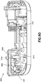
- Fig. 20 is a perspective view of the device 100 in the pre-activated stage, with several elements removed for illustrative purposes.
- the protrusion 188 and the slider-engaging surface 194 of the needle actuation plunger 166 engage the slider 196 at the first end thereof.
- the slider 196 engages the movable switch arm 206, the post 208 of which engages the rocker 128.
- the detents or wings 210 of the needle arm 130 are disposed on the loading cliffs 214 of the slider 196.
- the user After removing the adhesive liner, the user secures the device 100 to the user's skin.
- the user slides the button 110 forward, and at the end of the forward motion, pushes button 110 down.
- this feels like a single motion. For example, it can feel like sliding the button 110 on a ramp with a flat (horizontal) portion at the top of the ramp.
- the downward push of the button 110 rotates the lever 132 about the pivots 134. This lever rotation moves the loading element 218 down to deflect a middle portion of the flexible needle arm 130, thereby loading the needle arm 130.
- the deflection of the middle portion of the needle arm 130 biases the first end of the needle arm 130 (and thereby, the patient needle 124) to rotate down. Because the wings 210 are still resting on the loading cliffs 214, however, the patient needle 124 is maintained within the device 100.
- the blocking arm 204 no longer prevents movement of the shutter latch 156.
- the needle actuation plunger 166 moves and the sloped side of the first engaging structure 202 of the needle actuation plunger 166 displaces the shutter 136 upward. This frees the needle actuation plunger 166 and the barrel plunger 152 to move longitudinally forward toward the second end of the main body 106 under the force of their respective springs 178 and 200.
- the needle actuation plunger 166 moves forward until the second engaging structure 186 contacts the second engaging surface 164 of the shutter 136.
- the spring 200 continues to move the plunger 166 forward.
- the timing of events can be varied without departing from the present invention's scope, it is preferable that the loading element 218 biases the patient needle prior to the initial forward movement of the needle actuation plunger 166.
- the slider 196 moves forward under the force of the spring 200, via the plunger 166, the end of the loading cliff 214 reaches the wings 210, and because of the bias induced by the loading element 218, the patient needle quickly rotates down to extend outside of the main body 106 and into skin of the patient, as shown in Fig. 22 .
- the wings 210 contact the depth stop 216 to limit movement of the patient needle 124.
- the insertion depth of the patient needle 124 is determined by the length of the patient needle 124 and the height of the depth stop 216.
- the pivot ledge 220 of the slider 196 moves over the loading element 218 of the lever 132, thereby preventing the lever 132 and the button 110 from moving upward, and maintaining the loading on the needle arm 130.
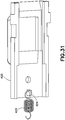
- the forward movement of the slider 196 also displaces the switch arm 206 forward. Because of the engagement of the post 208 with the rocker 128, as shown in Fig. 21 , the forward motion of the switch arm 206 rotates the rocker 128 about a rocker pivot 230, thereby displacing the valve plate 232 toward the first end of the bottom cover 204.
- the valve includes a valve septum 236 (see, for example, Fig. 31 ) disposed at the forward end of the syringe 108, and the valve needle 234 fixedly connected to the valve plate 232.
- the valve needle 234 is a whitacre needle having a conical tip and a side port (see Fig. 31 ). The shape of the whitacre needle 234 prevents coring of the valve septum 236. As the valve needle 234 is displaced by the motion of the rocker 128, the side port passes through the valve septum and communicates with the medicament in the syringe 108.
- valve needle 234 communicates with the tubing 228, which is connected to the patient needle 124 at the port 238 on the needle arm 130.
- valve needle can be fixed relative to the main body 106 and the valve septum can move to complete the fluid connection between the syringe 108 and the patient needle 124.
- valve mechanisms or assemblies without a needle and septum can be employed.
- the portion of the stage-indicating structure 226 visible through the status viewport 112 changes from the area 227 to the area 229, indicating the change from the pre-activation stage to the first activation stage.
- the leg posts 244 of the switch arm 206 enter a floor recess 242 (best shown in Fig. 20 ) in the bottom cover 204 and the switch arm 206 drops down.
- this permits the second, or front end of the slider 196 to travel over a portion of the switch arm 206 during the second activation stage.
- This functionality permits a greater travel for the slider 196 within the confines of the main body 106. In other words, it allows the device 100 to be more compact.
- the barrel plunger 152 moves longitudinally forward toward the second end of the main body 106 under the force of the barrel spring 178, thereby moving the stopper 172 forward. This pressurizes the medicament in the syringe 108.
- the release of the barrel plunger 152 and the needle activation plunger 166 from the shutter 136 is substantially simultaneous, their release and subsequent forward motions are independent.
- the timing of events can be determined.
- the barrel plunger hooks 176 engage the stopped ends of the stopped grooves 182.
- the biasing arm 158 of the shutter 136 displaces the shutter 136 toward the barrel side of the bottom cover 104, thereby automatically initiating the second activation stage or end-of-dose stage.
- the length of the sliding arms can be varied to vary the timing of the end-of-dose stage initiation.
- the second engaging surface 164 of the shutter 136 slides out of engagement with the second engagement structure or foot 186 of the needle actuation plunger 166. Because of the continued forward bias by the needle actuation spring 200, the needle actuation plunger 166 displaces further forward and drives the slider 196 further forward and over the rear portion of the switch arm 206. Briefly, this secondary forward movement of the slider 196 retracts the patient needle 124, rotates the lever 132 upward and raises the button 110, and makes the end-of-dose indicator 231 visible through the status viewport 212.
- the needle-retracting ramps 222 of the slider 196 engage the wings 210, thereby retracting the patient needle 124 back into the main body 106.
- the pivot ramps 224 of the slider 196 engage the loading element 218 of the lever 132 and rotate the lever 132 back up about the pivot 134, thereby releasing the loading of the needle arm 130 and raising the button 110, as shown in Fig. 23 .
- the portion of the stage-indicating structure 226 visible through the status viewport 112 changes to the area 231, indicating the change from the first activation stage to the second activation stage (or end-of-dose stage).
- continued forward motion of the slider 196 is prevented by interference with the main body 106.
- the user can remove the device 100 from his or her skin and safely dispose of the device 100.
- Figs. 25 and 26 illustrate another embodiment of a needle cover 400.
- Fig. 25 is a cross sectional view of a port 300, the patient needle 124, and a needle cover portion 302 that includes a tab 304.
- One end of the tubing 228 connects to the valve plate 232 and the other end connects to the port 300.
- the needle cover 302 is manufactured in a two-shot molding process, with a first molding shot portion 306 and a second molding shot portion 308.
- a button locking portion 402 forms the needle cover 400.
- the button lock portion 402 includes a safety extension 404 that engages the button or actuation button in a similar manner as the previously-described safety extension 120.
- this embodiment permits the needle cover portion 302 (along with the port, the patient needle, and other components of the fluid pathway) to be sterilized prior to assembly with the button lock portion 402.
- the button lock portion 402 and the needle cover portion 302 can be joined in several different ways, or a combination of ways, including snap-fit features, a friction fit, and an adhesive.
- the medical device can include a feature for retracting the actuation button to an initial position if the button is displaced subsequent to the removal of the needle cover, but not sufficiently displaced to activate the device.
- Figs. 27 and 28 illustrate a mechanism for retracting the actuation button 406.
- a fixed pin 410 is fixedly disposed in the lever or lift lever 408 and a movable pin 412 is fixedly connected to the underside of the button 406, but permitted to move in a slot 414 in the lift lever 408.
- the pins 410 and 412 are held in place by friction, but other methods of securing the pins 410 and 412, such as an adhesive, can be employed without departing from the present invention's scope.
- a spring 416 connects the two pins 410 and 412. If the button 406 is displaced by a distance that is insufficient to activate the device and subsequently released, the spring 416 retracts the movable pin 412 (and thus, the button 406) to its initial position. For example, if the user does not apply sufficient force to the button 406 to activate the device and then releases it, the button 406 will return to its initial position. This feature can help prevent accidental actuation and aid device assembly.
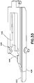
- both the lift lever 418 and the button 420 include hooks. More specifically, as shown in Figs. 29 and 30 , the lever 418 has a lever hook 422 disposed on a top thereof, and as shown in Fig. 31 , the button 420 has a button hook 424 disposed on its bottom side. A spring 426 connects the two hooks 422 and 424. The button hook 424 travels in a slot 428 in the lever 420 when the button is displaced.
- the spring 426 retracts the button hook 424 (and thus, the button 420) to its initial position shown in Fig. 29 .
- the slot 428 and the positioning of the lever hook 422 to the rear of the lever 418 provides additional clearance for the needle arm and port when the needle is retracted.
- Fig. 32 is a perspective view of a locking mechanism for selectively preventing activation of a drug delivery device in accordance with an embodiment of the present invention.
- the mechanism includes a needle cover 430 with a safety extension 432, a lift lever 434, and an actuation button 436.
- the button 436 includes a pair of flexible, cantilevered snap arms 438 separated laterally by a distance substantially equal to a lateral dimension of the proximal end of the safety extension 432.
- a pair of angled locking protrusions 440 is respectively disposed at the free ends of the snap arms 438.
- the lift lever 434 includes a track 442 that the snap arms 438 ride against.
- the track 442 has a pair of detents 444 and 446.
- the snap arms 438 are held in place or locked against the track 442 by the needle cover 430.
- the safety extension 432 prevents the snap arms 438 from displacing toward each other and disengaging from the detents 444.
- the actuation button 436 includes at least one cantilevered snap arm 438, and prior to needle cover removal, the snap arm 438 engages a detent 444 in the device and the safety extension 432 contacts the snap arm 439 and prevents the snap arm 438 from disengaging from the detent 444.
- the button 436 When the button 436 is in the initial position and the needle cover 430 is removed, unless the user applies sufficient force to deflect the snap arms 438 inward and engage the locking protrusions 440 with the detents 446, the interaction between the forward angled faces of the detents 444 and the forward angled faces of the locking protrusions 440, combined with the flexibility of the snap arms 438, causes the button 436 returns to its initial position with the locking protrusions engaged with the detents 444.
- the angles of the forward faces of the locking protrusions 440 and the forward faces of the detent 444 can be modified to adjust a force profile required from the user to activate the medical device.
- the obtuse angle between the of the forward face of the locking protrusion 440 and the straight portion of the snap arms 438 can be increased (and the corresponding angle of the forward face of the detent 444 can be modified) to lower the amount of force required by a user to overcome the interaction with the detent 444 and activate the device.
- the force required to activate the device is between about 4-10 N (0.9-2.2 1b F ).
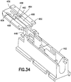
- FIG. 34 and 35 another embodiment of a stage-indicating mechanism is illustrated in Figs. 34 and 35 .
- the mechanism includes an indicator 448 and an indicator guide 450.
- the indicator guide 450 is fixedly connected to the top cover 452 and includes a cantilevered arm 454 and a guide slot 456 vertically supporting and guiding the indicator 448.
- the free end of the cantilevered arm 454 includes an indicator face 458 and an angled sliding surface 460. Prior to activation, the indicator face 458 is visible through the status viewport of the top cover 452 to indicate that the device has not yet been activated. This embodiment provides more room for assembling fluid path components in the device.
- the top surface of the indicator includes an area indicating the first activation stage 464 and an area indicating the second activation stage 466.
- the end of indicator has an angled surface 468 that is substantially complimentary to the angled sliding surface 460 of the cantilevered arm 454.
- the slider 462 displaces forward by a first distance (permitting the needle insertion into the user).
- the first forward displacement of the slider also displaces the indicator 448 forward.
- the forward displacement of the indicator 448 causes the angled surface 468 to ride over the angled sliding surface 460, downwardly deflecting the free end of the cantilevered arm 454, and displaying the area indicating the first activation stage 464 through the status viewport.
- the slider 462 displaces forward by a second distance, and displaces the indicator 448 forward to display the area indicating the second activation stage 466 through the status viewport.
- Fig. 36 illustrates another embodiment of the needle activation slider or slider 470. Similar to the slider 196, in this embodiment, the slider 470 includes a stage-indicating structure 472 fixedly connected thereto. But rather than being disposed at the forward end, in this embodiment, the stage-indicating structure 472 is disposed on the side of the slider 470.
- the stage-indicating structure 472 includes an area indicating the pre-activated stage 474, and area indicating the first activation stage 476, and an area indicating the second activation stage 478. As shown in Fig. 37 , the various stage-indicating areas (474, 476, and 478) are visible through the status viewport 480 of the top cover 482.
- Fig. 38 illustrates another embodiment of a switch arm or flip arm 484.
- the rear portion of the switch arm 484 resides in a recess of the needle activation slider 462, as shown in Fig. 39 .
- the bottom cover 486 includes a switch arm track 488 for guiding movement of the switch arm 484.
- Fig. 41 illustrates the switch arm prior to activation of the device.
- Front protrusions 490 rest on an upper track portion 492 and the rear portion of the switch arm 484 rests on the initial track portion 494.
- the slider 462 displaces forward by a first distance, displacing the switch arm 484 forward (to rotate the rocker) until the rear portion of the switch arm 484 falls off the initial track portion onto a lower track portion 496.
- the slider 462 can pass over the rear portion of the switch arm 484 without further displacing the switch arm 484 during the second activation stage. This configuration allows the slider 462 to travel a greater internal total distance
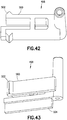
- Figs. 42 and 43 are respective top and bottom perspective views of a switch arm or flip arm 498 in accordance with another embodiment of the present invention.
- the switch arm 498 includes a pair of rear cantilevered arms 500, each having a snap protrusion 502 on its free end.
- the switch arm 498 also includes a guide rail 504 disposed on a bottom thereof that rides in a guide track in the bottom cover (not shown) to guide movement of the switch arm 498.
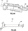
- the snap protrusions 502 rest against the forward end of the slider 470. Subsequent to activation, during the first activation stage, the slider 470 displaces forward by a first distance, displacing the switch arm 498 forward (to rotate the rocker) to its final forward position. According to one embodiment, at the beginning of the second activation stage, the slider 470 displaces further forward, but because the switch arm 498 does not displace further forward, the forward end of the slider 470 rides against the angled surfaces of the snap protrusions 502, deflecting the two cantilevered arms 500 toward each other. Further forward motion of the slider 470 bypasses the snap protrusions 502, as shown in Fig.
- the slider 470 includes a rear protrusion 471 for registration with the needle actuation plunger.
- Figs. 45 and 46 illustrate alternative embodiments of the needle arm.
- the needle arm 506 includes two pair of substantially vertical guide posts 508 for guiding installation and preventing lateral displacement of the tubing of the fluid pathway.
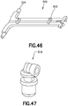
- the needle arm 510 of Fig. 46 includes two pairs of snap guides 512 to which the tubing is secured during installation.
- the pivots 514 and the corresponding pivot yokes 516 see, for example, Fig. 40 ).
- Fig. 47 is a top perspective view of a port 518 in accordance with an embodiment of the present invention.
- the port 518 makes a substantially horizontal connection with the tubing. This provides for less bending of the tubing during installation and additional clearance for the tubing once the needle is withdrawn.
- Fig. 48 is a rear perspective view of a power module of the device 100, illustrating the relative positioning of the frame 138, the shutter 136, and the needle actuation plunger 166 prior to activation of the device 100.
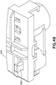
- Fig. 49 illustrates another embodiment of the frame 520 that substantially encloses the shutter except for its top, and supports the bottom of the needle actuation plunger 522 during its travel.
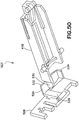
- Fig. 50 is a bottom perspective view of a shutter latching mechanism 523 in accordance with an embodiment of the present invention.
- the shutter latching mechanism of this embodiment includes the lift lever 418, a latch beam 424, the shutter latch 526, and the shutter 528 illustrated prior to activation
- the lift lever 418 (also shown in Fig. 30 ) includes a lifting arm 530 that engages the latch beam 424, which keeps the shutter latch 526 engaged with the shitter 528.
- the latch beam 524 is an L-shaped element having a long portion 532 and a short portion 534. According to one embodiment, the short portion 534 is secured in a pocket of the frame 520.
- the latch beam 424 is made of sheet metal or spring metal, and is strong but flexible.
- the front portion of the lift lever 418 rotates down (due to the user force on the button), thereby rotating the rear portion of the lift lever 418 up and lifting or deflecting the long portion 532 of the latch beam 524 so that it no longer contacts and supports the shutter latch 526.
- the shutter latch 526 is freed from the shutter 528 and the needle actuation plunger 522 lifts the shutter 528.
- Fig. 51 is a bottom perspective view of a shutter latching mechanism 535
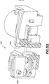
- Fig. 52 is a rear perspective cross-sectional view of a frame or power module frame 541.
- the shutter latching mechanism of this embodiment includes the lift lever 434, a swing arm 536, the shutter latch 538, and the shutter 540 illustrated prior to activation in accordance with an embodiment of the present invention.
- the lift lever 434 (also shown in Fig. 33 ) includes a lifting arm 542 that engages the swing arm 536, which selectively keeps the shutter latch 538 engaged with the shutter 540.
- the swing arm 536 is rotatably connected to the frame 541 at a stud 543 (see Fig. 52 ), and is preferably made of plastic. Prior to activation, the free end of the swing arm 536 is disposed beneath a frame protrusion 545.
- the front portion of the lift lever 434 rotates down (due to the user force on the button), thereby raising the lifting arm 542 and rotating the swing arm 536 so that the free end is disposed above the frame protrusion 545 and the swing arm 536 no longer contacts and supports the shutter latch 538.
- the shutter latch 538 is freed from the shutter 540 and the needle actuation plunger 548 (see Fig. 54 ) lifts the shutter 540.
- the swing arm 536 and the shutter latch 538 are located on the rear side of the shutter 540 and frame 541.
- This arrangement combined with the longer lifting arm 542 increases the lifting arm's effective travel.
- being able to make the swing arm out of plastic and its arrangement in the mechanism helps prevent creep prior to activation of the device.
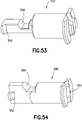
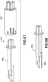
- Figs. 53 and 54 are top perspective views of needle actuation plungers in accordance with embodiments of the present invention.
- the needle actuation plunger 522 (also shown in Fig. 49 ) has a lower first engaging structure 544, and the second engaging structure 546 is angled.
- the needle actuation plunger 548 in Fig. 54 has a similar configuration with a lower first engaging structure 550 and an angled second engaging structure 552.
- the needle actuation plunger 548 has a cavity 553 with a front opening that receives the slider's rear protrusion 471 (shown in Fig. 44 ).
- the needle actuation plungers 522 and 548 can be made of plastic or metal, for example, aluminum.
- the lower first engaging structures 544 and 550 do not lift the shutter as high, and the angled second engaging structures 546 and 552 provide the side force to the shutter once the sliding arms 144 of the outer telescope member 146 displace and no longer contact the shutter, thereby eliminating the need for the biasing arm 158 of the shutter 136.
- the shutter 528 shown in Figs. 50 and 55
- the shutter 540 shown in Figs. 51 and 56
- Fig. 57 illustrates an embodiment of a two-part barrel plunger 554, which includes a plunger portion 556 and a plunger link 558.
- both the plunger portion 556 and the plunger link 558 have a cruciform shape.
- the plunger portion cruciform engages the barrel stopper and the plunger link cruciform engages the interior of the plunger portion cruciform, securing the two elements and preventing their relative rotation. Shapes other than a cruciform can be used without departing from the present invention's scope.
- Fig. 58 illustrates a plunger link 560 in accordance with another embodiment of the present invention.
- the plunger link 560 includes a lift ramp 562 for lifting the shutter in concert with the needle actuation plunger's first engaging structure. Having both elements lift the shutter substantially simultaneously and to substantially the same height reduces the likelihood that the shutter will rack during lifting.
- Fig. 59 is a top perspective view of a medical device 600 incorporating selected ones of the previously-described features.
- the device 600 includes the frame 541, the swing arm 536, the needle cover 430, the lift lever 434, the actuation button 436, the needle activation slider 470, the needle arm 506, and the switch arm 498.
- the device 600 also includes a valve assembly 602, which includes the rocker 604, a valve release cap 606, and a septum fitting 608 disposed about the valve release cap 606, as shown in Fig. 59 .
- the septum fitting 608 has a side port 618 connected to tubing 610 that fluidly connects to the patient needle.
- the rocker 604 has a pair of arms 612.
- the ends of the rocker arms 612 include angled faces 614.
- the rocker arms splay apart the septum fitting's cantilevered base arms 616.
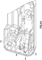
- Fig. 62 is an exploded view illustrating additional components of the valve assembly 602
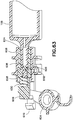
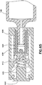
- Fig. 63 is a cross-sectional perspective plan view of the valve assembly 602.
- the septum fitting 608 includes teeth 620 at its first end that correspond with teeth 622 disposed at a first end of a one-piece plug valve 624, to prevent relative rotation between the septum fitting 608 and the plug valve 624.
- the plug valve 624 has a central lumen that fluidly communicates with the tip of the syringe barrel 108, and also has a side port 626 connected with the central lumen and aligned with the septum fitting's side port 618.
- the valve release cap 606 includes an end block 634 for securing the valve release cap 606 in a pre-activated position, and a guide block 636 that rides against a registration surface of the septum fitting 608 to prevent relative rotation between the septum fitting 608 and the valve release cap 606.
- retaining protrusions at the free end of the septum fitting's base arms 616 retain an end block 634 of the valve release cap 606.
- An inner spring 630 is disposed within a cavity 632 of the valve release cap 606 and biases a valve impactor 628 toward the syringe barrel 108. Under the force of the inner spring 630, the valve impactor contacts and elastically deforms the end of the plug valve, thereby causing an internal valve protrusion 638 to seal the syringe barrel tip 626 and prevent medicament in the syringe barrel 108 from flowing through the side ports 626 and 618.
- the plug valve 624 returns to its un-deformed shape, displacing the internal valve protrusion 638 out of sealing engagement with the tip of the syringe barrel 108 and permitting medicament in the syringe barrel 108 to flow through the side ports 626 and 618.
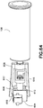
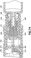
- Fig. 66 is a bottom perspective view of a valve assembly 640 and Fig. 67 is a partial, cross-sectional, plan view of the valve assembly 640.
- Figs. 66 and 67 illustrate a state prior to device activation.
- the valve assembly includes a lid 642 hingedly connected to a lid retainer 644, a valve case 646 connected with the tip of the syringe barrel 108, a valve body 648 disposed within the valve case and having a central lumen 650 fluidly communicating with the interior of the syringe barrel 108, an elastomeric valve member 652, and a cover 654 securing the valve member 652 to the valve body 648.
- the lid retainer 644 includes a cantilevered retainer arm 656 with a catch 658 to selectively retain the lid 642.
- the lid 642 includes a lid protrusion 660 for selectively compressing the valve member 652 to seal the valve body's central lumen 650.
- the valve member 652 includes one or more sealing protrusions 662 (for example, a protrusion and a ring) that seal the central lumen 650 when the valve member 652 is compressed by the lid 642.
- the valve member 652 also includes a side port 664 for communicating with the patient needle via the tubing.
- an angled rocker arm (not shown) wedges up the retainer arm 656 freeing the catch 658 from the lid 642.
- the valve body 648 returns to its un-deformed shape, and rotates the lid away from the syringe barrel 108 while unsealing the central lumen 650, thereby permitting the medicament to flow from the syringe barrel 108, through the central lumen 650, and through the interior of the valve body 648 to the side port 664.
- suitable plastics such as ABS.
- Other suitable plastics can also be employed.
- Fig. 68 illustrates a tub 262 for containing and processing (for example, filling) syringes, such as 10 mL BD HypakTM syringes.
- syringes such as 10 mL BD HypakTM syringes.
- the tub can be a ten centimetre (four inch) tub and can accommodate 42 barrels (HypakTM syringes) per tub.
- the manufacturing process for the device 100 utilizes components that allow for the use of such tubs and standard syringe processing equipment.
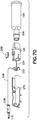
- Fig. 69 is a perspective view of a fluid path subassembly 264 in accordance with an embodiment of the present invention
- Fig. 70 is an exploded perspective view of the fluid path subassembly 264.
- the fluid path subassembly 264 includes the syringe barrel 108, the stopper 172 (not shown in Figs. 69 and 70 ), the valve cover 126, an adapter 266 for connecting the syringe barrel 108 with the valve cover 126, the hollow valve needle 234, the valve plate 232, and a locking element or lock 268 to selectively prevent the valve plate 232 from moving with respect to the valve cover 126.
- the valve septum 236 is disposed within the adapter 266.
- the fluid path subassembly 264 also includes the connecting tube 228, the port or needle hub 238, the hollow patient needle 124, the needle cover 114, and a sacrificial retainer 270 for holding the components of the fluid path subassembly 264 prior to installation in the bottom cover 104.
- the fluid path subassembly 264 includes all of the elements of the device that contact the medicament fluid plus the retainer 270 and the locking element 268. Additionally, the elements of the fluid path subassembly 264 minus the barrel 108 and the stopper 172 form a flow pathway subassembly 272, as subsequently described in greater detail.
- fluid path subassembly 264 in this embodiment is envisioned to be used in device 100, such a fluid path subassembly can also be utilized in other types of devices, such as autoinjectors, medication pens, and virtually any pre-filled device that requires sterility maintenance in the fluid path.
- the retainer 270 is re-usable.
- the retainer also includes a balancing feature or balancing weight 274 (see Fig. 69 ) for balancing the flow pathway subassembly 272 (as well as the fluid path subassembly 264) about its central longitudinal axis.
- the center of gravity of the flow pathway subassembly 272 is disposed on the central longitudinal axis, so that the subassembly 272 is rotationally balanced about the central longitudinal axis.
- the balancing weight 274 can be connectable to the main body of the retainer 270, or alternatively, can be integrally formed with the main body of the retainer 270. According to one embodiment, the balancing weight 274 is adjustable relative to the main body of the retainer 270. For example, the balancing weight 274 can be affixed to different locations on the main body of the retainer 270. Alternatively, if the balancing weight 274 is integrally formed with the retainer's main body, for example, as a weight at the end of a cantilevered arm, the arm can be deformed or deflected to position the balancing weight 274.
- the fluid path subassembly 264 is rotated at high speeds about its central longitudinal axis (for example, axis A in Fig. 69 ), so it is preferable that it be rotationally balanced about that axis).
- the retainer 270 has a path for looping and storing the connecting tube 228. This provides for space-efficient storage of the connecting tube 228, as well as protection for the tube 228. The retainer 270 also provides for convenient handling of the fluid path subassembly 264.
- the fluid path subassemblies 264 which are substantially the same size as a 10 mL BD HypackTM barrel, can be loaded into a ten centimetre (four inch) tub that can accommodate 42 fluid path subassemblies 264. Because of the additional components in a fluid path subassembly 264, the syringe barrel 108 is smaller than a 10 mL HypakTM barrel. According to one embodiment, the syringe barrel 108 can be filled with about 2-5 mL of medicament. Because of the size similarity of the fluid path subassembly 264 with respect to a HypakTM barrel, equipment standardized for filling and moving HypakTM barrels can be utilized to fill and move fluid path subassemblies 264.
- the medicament fluid path is self-contained, and therefore, sterile packaging or storage is not required. Instead, the fluid path subassemblies 264 can be stored and subsequently installed into the device 100 in a standard clean room.
- the installer unwinds the tubing 228 from the retainer 270, which is then discarded, re-used, or recycled.
- the installer secures the needle hub or port 238 at the end of the needle arm 130 and inserts the barrel 108 and valve cover 126 into the bottom cover 104, as shown in Fig. 71 .
- the installer removes the locking element 268, which is then also discarded, re-used, or recycled.
- Figs. 25 and 72-76 illustrate another embodiment of a fluid path subassembly 278.
- the retainer 280 includes first and second retaining members 282 and 284.
- the syringe barrel 108, the stopper 172, the valve cover 126, valve plate 232, the valve needle 234, the patient needle 124, and the tubing 228 are substantially similar to those previously described. Accordingly, the description of these elements is omitted for brevity.
- the valve cover 126 is omitted from Fig. 73 for clarity.
- the first and second retaining members 282 and 284 have inward-protruding walls to engage the valve plate 232 and fix its position within the valve cover 126.
- the retainer 280 prevents movement of the valve plate 232 relative to the valve cover 126.
- the retainer 280 has a balancing weight (not shown) similar to the previously-described balancing weight 274, to ensure that the center of gravity of the flow path assembly 278 lies on the central longitudinal axis thereof.
- a two-piece adapter 288 includes a septum holder 290 and a connector 292 for connecting to a neck of the tip of the syringe barrel 108.
- the septum holder 290 secures a valve septum 294 that is penetrated by the whitacre valve needle 234.
- the arms 258 and hooks 260 of the valve cover 126 secure the two-piece adapter 288 within the valve cover 126.
- the septum holder 290 and the connector 292 have mating screw threads 296 and 298 to secure one to the other.
- Fig. 77 is a flow chart illustrating a process 310 of assembly of the device 100.
- the assembler obtains or manufacturers the spring components of the device 100, for example, the barrel spring 178 and the needle actuation spring 200.
- the assembler molds or obtains the injection molded components, for example, the main body 106, the needle actuation plunger 166, the outer telescope member 146, and the retainer 270 or 280.
- the assembler obtains or manufactures the primary container, for example, the syringe barrel 108.
- the assembler obtains or manufactures the remaining components of the flow pathway subassembly 272, for example, the patient needle 124, the valve needle 234, the tubing 228, and the stopper 172.
- the assembler assembles the power pack 1380 using the spring components and the appropriate injection-molded components, for example, the needle actuation plunger 166, and the barrel plunger 152. Additionally, the fluid path subassembly 264 or 278 is assembled in operation 322. The remainder of the components, i.e., those that are not in the power pack 1380 or the fluid path subassembly 264 or 278, are assembled into the device body 1060.
- the assembled fluid path subassembly 264 or 278 is packaged (operation 326) and then sterilized (operation 328), thereby providing a self-contained, sterilized fluid path subassembly 264 or 278 that can be shipped to another location, for example, a pharmaceutical manufacturer, for aseptic filling (operation 330) with medicament.
- the fluid path subassembly 264 or 278 is inspected for quality during high-speed rotation about its central longitudinal axis, for example, by a light-based inspection system, such as a laser inspection system.
- inventive fluid path subassembly is that it can be processed (i.e., packaged, sterilized, filled, and inspected) using equipment that is standardized for processing syringes, such as BD HypakTM syringes. Those fluid path subassemblies that pass inspection can then be assembled into the device body 1060 along with the power pack 1380 to complete the device (operation 334).
Landscapes
- Health & Medical Sciences (AREA)
- Engineering & Computer Science (AREA)
- Hematology (AREA)
- Anesthesiology (AREA)
- Biomedical Technology (AREA)
- Heart & Thoracic Surgery (AREA)
- Vascular Medicine (AREA)
- Life Sciences & Earth Sciences (AREA)
- Animal Behavior & Ethology (AREA)
- General Health & Medical Sciences (AREA)
- Public Health (AREA)
- Veterinary Medicine (AREA)
- Dermatology (AREA)
- Mechanical Engineering (AREA)
- Infusion, Injection, And Reservoir Apparatuses (AREA)
Claims (10)
- Fluidweg-Baugruppe (264, 278) mit:Medikamentenfließwegkomponenten (108, 172, 126, 266, 234, 232, 268, 288) einer medizinischen Vorrichtung; undeinem Halter (270, 280), der dazu ausgebildet ist, die Komponenten vor der Montage der Komponenten in die Vorrichtung zu halten, so dass ein Schwerpunkt der Baugruppe im Wesentlichen auf einer Mittellängsachse der Baugruppe angeordnet ist;wobei der Halter aufweist:einen Hauptkörper; undeiner Ausgleichseinrichtung (274) zum Einstellen des Schwerpunkts der Baugruppe.
- Baugruppe nach Anspruch 1, bei welcher die Ausgleichseinrichtung (274) mit dem Hauptkörper verbindbar ist.
- Baugruppe nach Anspruch 1, bei welcher der Halter (270, 280) die Komponenten in einer im Wesentlichen festen Position in Bezug auf den Halter hält.
- Baugruppe nach Anspruch 1, bei welcher die Medikamentenfließwegkomponenten aufweisen:eine Ventilanordnung (602, 640), welche mit einem Spritzenzylinder (108) verbindbar ist;eine Schlauchleitung (228), die an einem ihrer Enden mit der Ventilanordnung verbunden ist;einen Port (238, 300, 518), der mit einem zweiten Ende der Schlauchleitung verbunden ist;eine Patientennadel (124), die mit dem Port verbunden ist, um einen Fluidweg von der Ventilanordnung durch die Patientennadel hindurch zu bilden; undeine Nadelabdeckung (114, 400, 430) zum Abdecken und Freilegen der Patientennadel.
- Baugruppe nach Anspruch 4, bei welcher der Halter eine Einrichtung zum Schleifen und Befestigen der Schlauchleitung aufweist.
- Baugruppe nach Anspruch 4, bei welcher die Ventilanordnung (602, 640) mit:einer mit dem ersten Ende der Schlauchleitung verbundenen Ventilplatte (232);einer Ventilabdeckung (126), welche die Ventilplatte zur Bewegung in dieser aufnimmt;wobei die Fließwegbaugruppe ferner ein entfernbares Verriegelungselement (268) aufweist, um ein Bewegung der Ventilplatte in Bezug auf die Ventilabdeckung zu verhindern.
- Baugruppe nach Anspruch 4, bei welcher die Nadelabdeckung ferner Sterilität bewirkt.
- Verfahren zum Montieren einer Medikamentenausgabevorrichtung mit den folgenden Schritten:A) Montieren einer Fluidwegbaugruppe (264, 278);B) Verpacken der Fluidwegbaugruppe und Sterilisieren der verpackten Fluidwegbaugruppe;C) aseptisches Füllen der sterilisierten Fluidwegbaugruppe;D) Inspizieren der gefüllten Fluidwegbaugruppe; undE) Montieren der gefüllten Fluidwegbaugruppe in einen Vorrichtungskörper,wobei der Schritt A das Zusammensetzen von Medikamentenfließwegkomponenten in einen Halter (270, 280) aufweist, der dazu ausgebildet ist, die Komponenten derart zu halten, dass ein Schwerpunkt der Baugruppe (264, 278) im Wesentlichen auf einer Mittellängsachse der Baugruppeangeordnet ist,
dadurch gekennzeichnet, dass
der Schritt A ferner das Einstellen einer Ausgleichseinrichtung (274) des Halters aufweist, um einen Schwerpunkt der Baugruppe auf eine Längsachse des Halters auszurichten. - Verfahren nach Anspruch 8, bei welchem der Schritt D das Drehen der Baugruppe um die Längsachse des Halters aufweist.
- Verfahren nach Anspruch 8, bei welcher die Schritte C und D in einer Einrichtung durchgeführt werden, die von einer Einrichtung verschieden ist, in welcher die Schritte A und B durchgeführt werden.
Applications Claiming Priority (2)
| Application Number | Priority Date | Filing Date | Title |
|---|---|---|---|
| US201361819443P | 2013-05-03 | 2013-05-03 | |
| PCT/US2014/036703 WO2014179776A1 (en) | 2013-05-03 | 2014-05-02 | Flow pathway subassembly |
Publications (3)
| Publication Number | Publication Date |
|---|---|
| EP2991707A1 EP2991707A1 (de) | 2016-03-09 |
| EP2991707A4 EP2991707A4 (de) | 2017-04-26 |
| EP2991707B1 true EP2991707B1 (de) | 2020-12-02 |
Family
ID=51844008
Family Applications (3)
| Application Number | Title | Priority Date | Filing Date |
|---|---|---|---|
| EP14791991.4A Active EP2991711B1 (de) | 2013-05-03 | 2014-05-02 | Arzneimittelabgabevorrichtung |
| EP14791686.0A Active EP2991707B1 (de) | 2013-05-03 | 2014-05-02 | Flusswegbaugruppe |
| EP22197787.9A Pending EP4134116A1 (de) | 2013-05-03 | 2014-05-02 | Arzneimittelabgabevorrichtung |
Family Applications Before (1)
| Application Number | Title | Priority Date | Filing Date |
|---|---|---|---|
| EP14791991.4A Active EP2991711B1 (de) | 2013-05-03 | 2014-05-02 | Arzneimittelabgabevorrichtung |
Family Applications After (1)
| Application Number | Title | Priority Date | Filing Date |
|---|---|---|---|
| EP22197787.9A Pending EP4134116A1 (de) | 2013-05-03 | 2014-05-02 | Arzneimittelabgabevorrichtung |
Country Status (11)
| Country | Link |
|---|---|
| US (2) | US10682458B2 (de) |
| EP (3) | EP2991711B1 (de) |
| JP (2) | JP6330029B2 (de) |
| CN (3) | CN105307709B (de) |
| AU (3) | AU2014259598B2 (de) |
| BR (2) | BR112015027723B1 (de) |
| CA (2) | CA2910689C (de) |
| ES (2) | ES2854949T3 (de) |
| MX (4) | MX2015015090A (de) |
| SG (3) | SG11201508647UA (de) |
| WO (2) | WO2014179776A1 (de) |
Families Citing this family (114)
| Publication number | Priority date | Publication date | Assignee | Title |
|---|---|---|---|---|
| DE602005023458D1 (de) | 2005-09-12 | 2010-10-21 | Unomedical As | Einfürungssystem für ein Infusionsset mit einem ersten und zweiten Federeinheit |
| US9656019B2 (en) | 2007-10-02 | 2017-05-23 | Medimop Medical Projects Ltd. | Apparatuses for securing components of a drug delivery system during transport and methods of using same |
| CN101868273B (zh) | 2007-10-02 | 2014-10-15 | 莱蒙德尔有限公司 | 外部药泵 |
| US10420880B2 (en) | 2007-10-02 | 2019-09-24 | West Pharma. Services IL, Ltd. | Key for securing components of a drug delivery system during assembly and/or transport and methods of using same |
| US7967795B1 (en) | 2010-01-19 | 2011-06-28 | Lamodel Ltd. | Cartridge interface assembly with driving plunger |
| US9345836B2 (en) | 2007-10-02 | 2016-05-24 | Medimop Medical Projects Ltd. | Disengagement resistant telescoping assembly and unidirectional method of assembly for such |
| US7959598B2 (en) | 2008-08-20 | 2011-06-14 | Asante Solutions, Inc. | Infusion pump systems and methods |
| US9393369B2 (en) | 2008-09-15 | 2016-07-19 | Medimop Medical Projects Ltd. | Stabilized pen injector |
| US8157769B2 (en) | 2009-09-15 | 2012-04-17 | Medimop Medical Projects Ltd. | Cartridge insertion assembly for drug delivery system |
| USD810278S1 (en) * | 2009-09-15 | 2018-02-13 | Medimop Medical Projects Ltd. | Injector device |
| US10071198B2 (en) * | 2012-11-02 | 2018-09-11 | West Pharma. Servicees IL, Ltd. | Adhesive structure for medical device |
| US8348898B2 (en) | 2010-01-19 | 2013-01-08 | Medimop Medical Projects Ltd. | Automatic needle for drug pump |
| CN102844060A (zh) | 2010-03-30 | 2012-12-26 | 犹诺医药有限公司 | 医疗装置 |
| WO2012123274A1 (en) | 2011-03-14 | 2012-09-20 | Unomedical A/S | Inserter system with transport protection |
| USD702834S1 (en) | 2011-03-22 | 2014-04-15 | Medimop Medical Projects Ltd. | Cartridge for use in injection device |
| WO2013050277A1 (en) | 2011-10-05 | 2013-04-11 | Unomedical A/S | Inserter for simultaneous insertion of multiple transcutaneous parts |
| EP2583715A1 (de) | 2011-10-19 | 2013-04-24 | Unomedical A/S | Infusionsschlauchsystem und Herstellungsverfahren |
| US9072827B2 (en) | 2012-03-26 | 2015-07-07 | Medimop Medical Projects Ltd. | Fail safe point protector for needle safety flap |
| US9421323B2 (en) | 2013-01-03 | 2016-08-23 | Medimop Medical Projects Ltd. | Door and doorstop for portable one use drug delivery apparatus |
| US9011164B2 (en) | 2013-04-30 | 2015-04-21 | Medimop Medical Projects Ltd. | Clip contact for easy installation of printed circuit board PCB |
| EP3268078B1 (de) | 2015-03-10 | 2020-11-04 | Regeneron Pharmaceuticals, Inc. | Aseptisches durchstechsystem |
| IL237788B (en) | 2015-03-16 | 2019-10-31 | Kriheli Marino | Septum holders used in injector connectors |
| US10293120B2 (en) | 2015-04-10 | 2019-05-21 | West Pharma. Services IL, Ltd. | Redundant injection device status indication |
| US9884175B2 (en) * | 2015-04-23 | 2018-02-06 | Freudenberg Medical, Llc | Automatic medical valve with a variable diameter seal |
| US11207512B2 (en) | 2015-04-23 | 2021-12-28 | Freudenberg Medical, Llc | Automatic medical valve with a variable diameter seal |
| US10149943B2 (en) | 2015-05-29 | 2018-12-11 | West Pharma. Services IL, Ltd. | Linear rotation stabilizer for a telescoping syringe stopper driverdriving assembly |
| US11207465B2 (en) | 2015-06-04 | 2021-12-28 | West Pharma. Services Il. Ltd. | Cartridge insertion for drug delivery device |
| US9987432B2 (en) | 2015-09-22 | 2018-06-05 | West Pharma. Services IL, Ltd. | Rotation resistant friction adapter for plunger driver of drug delivery device |
| US10576207B2 (en) | 2015-10-09 | 2020-03-03 | West Pharma. Services IL, Ltd. | Angled syringe patch injector |
| US11318254B2 (en) | 2015-10-09 | 2022-05-03 | West Pharma. Services IL, Ltd. | Injector needle cap remover |
| USD801346S1 (en) * | 2015-12-04 | 2017-10-31 | Hand Held Products, Inc. | Wearable module |
| USD808517S1 (en) * | 2015-12-11 | 2018-01-23 | Nuance Designs Of Ct, Llc | Wearable autoinjector |
| EP3374905A1 (de) | 2016-01-13 | 2018-09-19 | Bigfoot Biomedical, Inc. | Benutzerschnittstelle für diabetesmanagementsystem |
| CN113101448B (zh) | 2016-01-14 | 2024-01-23 | 比格福特生物医药公司 | 调整胰岛素输送速率的系统 |
| US11357912B2 (en) | 2016-01-19 | 2022-06-14 | Unomedical A/S | Cannula and infusion devices |
| EP3405229A1 (de) | 2016-01-21 | 2018-11-28 | West Pharma. Services Il, Ltd. | Nadeleinführ- und retraktionsmechanismus |
| CN111544704B (zh) | 2016-01-21 | 2022-06-03 | 西医药服务以色列有限公司 | 自动注射器中的力牵制 |
| US11311674B2 (en) | 2016-01-21 | 2022-04-26 | West Pharma. Services IL, Ltd. | Medicament delivery device comprising a visual indicator |
| US11389597B2 (en) | 2016-03-16 | 2022-07-19 | West Pharma. Services IL, Ltd. | Staged telescopic screw assembly having different visual indicators |
| US10342926B2 (en) * | 2016-05-26 | 2019-07-09 | Insulet Corporation | Single dose drug delivery device |
| JP6957525B2 (ja) | 2016-06-02 | 2021-11-02 | ウェスト ファーマ サービシーズ イスラエル リミテッド | 3つの位置による針の退避 |
| US20170348479A1 (en) | 2016-06-03 | 2017-12-07 | Bryan Choate | Adhesive system for drug delivery device |
| TWI746569B (zh) | 2016-06-08 | 2021-11-21 | 瑞士商瑞健醫療股份有限公司 | 計量器具、注射裝置、及其應用 |
| US10773024B2 (en) * | 2016-06-09 | 2020-09-15 | Becton, Dickinson And Company | Drive assembly for drug delivery system |
| US10751476B2 (en) * | 2016-06-09 | 2020-08-25 | Becton, Dickinson And Company | Actuator assembly for drug delivery system |
| US10603445B2 (en) | 2016-06-09 | 2020-03-31 | Becton, Dickinson And Company | Needle actuator assembly for drug delivery system |
| US10549044B2 (en) | 2016-06-09 | 2020-02-04 | Becton, Dickinson And Company | Spacer assembly for drug delivery system |
| US10792432B2 (en) | 2016-06-09 | 2020-10-06 | Becton, Dickinson And Company | Drive assembly and spacer for drug delivery system |
| CN109562220B (zh) | 2016-08-01 | 2021-06-29 | 西医药服务以色列有限公司 | 部分门关闭防止弹簧 |
| EP3490643B1 (de) | 2016-08-01 | 2021-10-27 | West Pharma. Services Il, Ltd. | Verdrehsicherungsstift |
| EP3730169B1 (de) | 2016-08-14 | 2023-08-02 | Insulet Corporation | Medikamentenverabreichungsgerät mit detektion der position des kolbens |
| USD804650S1 (en) * | 2016-09-26 | 2017-12-05 | West Pharmaceutical Services, Inc. | Injector device |
| USD805187S1 (en) * | 2016-09-26 | 2017-12-12 | West Pharmaceutical Services, Inc. | Injector device |
| USD805190S1 (en) * | 2016-09-26 | 2017-12-12 | West Pharmaceutical Services, Inc. | Injector device |
| USD805188S1 (en) * | 2016-09-26 | 2017-12-12 | West Pharmaceutical Services, Inc. | Injector device |
| USD804019S1 (en) * | 2016-09-26 | 2017-11-28 | West Pharmaceutical Services, Inc. | Injector device |
| USD805189S1 (en) * | 2016-09-26 | 2017-12-12 | West Pharmaceutical Services, Inc. | Injector device |
| USD805186S1 (en) * | 2016-09-26 | 2017-12-12 | West Pharmaceutical Services, Inc. | Injector device |
| USD878555S1 (en) | 2016-10-26 | 2020-03-17 | West Pharmaceutical Services, Inc. | Injector device |
| USD807499S1 (en) | 2016-10-26 | 2018-01-09 | West Pharmaceutical Services, Inc. | Injector device |
| USD808011S1 (en) | 2016-10-26 | 2018-01-16 | West Pharmaceutical Services, Inc. | Injector device |
| USD805633S1 (en) | 2016-10-26 | 2017-12-19 | West Pharmaceutical Services, Inc. | Injector device |
| USD878557S1 (en) | 2016-10-26 | 2020-03-17 | West Pharmaceutical Services, Inc. | Injector device |
| USD806235S1 (en) | 2016-10-26 | 2017-12-26 | West Pharmaceutical Services, Inc. | Injector device |
| USD882765S1 (en) | 2016-10-26 | 2020-04-28 | West Pharmaceutical Services, Inc. | Injector device |
| USD806234S1 (en) | 2016-10-26 | 2017-12-26 | West Pharmaceutical Services, Inc. | Injector device |
| USD806863S1 (en) | 2016-10-26 | 2018-01-02 | West Pharmaceutical Services, Inc. | Injector device |
| USD878556S1 (en) | 2016-10-26 | 2020-03-17 | West Pharmaceutical Services, Inc. | Injector device |
| USD805632S1 (en) | 2016-10-26 | 2017-12-19 | West Pharmaceutical Services, Inc. | Injector device |
| WO2018096149A1 (de) | 2016-11-28 | 2018-05-31 | Idorsia Pharmaceuticals Ltd | Vorrichtung zur abgabe einer substanz |
| USD839411S1 (en) * | 2016-12-15 | 2019-01-29 | Novartis Ag | Auto-injector |
| US11027063B2 (en) | 2017-01-13 | 2021-06-08 | Bigfoot Biomedical, Inc. | Insulin delivery methods, systems and devices |
| WO2018136699A1 (en) | 2017-01-19 | 2018-07-26 | Insulet Corporation | Cartridge hold-up volume reduction |
| USD872734S1 (en) | 2017-03-14 | 2020-01-14 | Insulet Corporation | Display screen with a graphical user interface |
| USD872733S1 (en) | 2017-03-14 | 2020-01-14 | Insulet Corporation | Display screen with a graphical user interface |
| WO2018189842A1 (ja) * | 2017-04-12 | 2018-10-18 | 光陽産業株式会社 | 医療用接続構造 |
| MA49549B1 (fr) | 2017-05-05 | 2022-05-31 | Regeneron Pharma | Auto-injecteur |
| US11040137B2 (en) * | 2017-05-19 | 2021-06-22 | Min Wei | Wearable drug delivery device |
| US11819666B2 (en) | 2017-05-30 | 2023-11-21 | West Pharma. Services IL, Ltd. | Modular drive train for wearable injector |
| EP3662161B1 (de) | 2017-08-03 | 2024-05-01 | Insulet Corporation | Mikrokolbenpumpe |
| WO2019032374A1 (en) | 2017-08-10 | 2019-02-14 | West Pharma, Services Il, Ltd. | INJECTOR DELAYED CARTRIDGE PUNCHING MECHANISM |
| USD836770S1 (en) * | 2017-09-25 | 2018-12-25 | Insulet Corporation | Drug delivery device |
| US11786668B2 (en) | 2017-09-25 | 2023-10-17 | Insulet Corporation | Drug delivery devices, systems, and methods with force transfer elements |
| CA3079353C (en) | 2017-10-16 | 2023-09-26 | Becton, Dickinson And Company | Connector for aseptic transfer of fluid |
| WO2019079181A1 (en) | 2017-10-16 | 2019-04-25 | Becton, Dickinson And Company | END OF DOSE DETECTION FOR DRUG DELIVERY SYSTEM |
| BR112020007283A2 (pt) | 2017-10-16 | 2020-11-03 | Becton, Dickinson And Company | arranjo de esterilização para dispositivo de administração de fármacos |
| BR112020007533A2 (pt) | 2017-10-16 | 2020-10-06 | Becton, Dickinson And Company | conjunto de espaçador para dispositivo de administração de fármacos |
| CN111372626B (zh) | 2017-10-16 | 2022-03-08 | 贝克顿·迪金森公司 | 用于药物输送装置的管夹压装置 |
| US11857767B2 (en) | 2017-12-22 | 2024-01-02 | West Pharma. Services IL, Ltd. | Injector usable with different dimension cartridges |
| US20220262529A9 (en) | 2018-01-02 | 2022-08-18 | Cerner Innovation, Inc. | Clinical Notifications |
| WO2019136064A1 (en) | 2018-01-02 | 2019-07-11 | Becton, Dickinson And Company | Port interface for drug delivery device |
| USD928199S1 (en) | 2018-04-02 | 2021-08-17 | Bigfoot Biomedical, Inc. | Medication delivery device with icons |
| US10874803B2 (en) | 2018-05-31 | 2020-12-29 | Insulet Corporation | Drug cartridge with drive system |
| AU2019308251B2 (en) | 2018-07-17 | 2023-05-18 | Insulet Corporation | Low force valves for drug delivery pumps |
| EP3632487A1 (de) | 2018-10-05 | 2020-04-08 | Sorrel Medical Ltd. | Auslösesequenz |
| CN113167258B (zh) | 2018-11-28 | 2023-05-12 | 英赛罗公司 | 药物输送往复泵系统和阀组件 |
| USD920343S1 (en) | 2019-01-09 | 2021-05-25 | Bigfoot Biomedical, Inc. | Display screen or portion thereof with graphical user interface associated with insulin delivery |
| CN109675141B (zh) * | 2019-01-31 | 2024-03-26 | 深圳中科生物医疗电子有限公司 | 一种传动部位置可调节的输注泵 |
| EP3958927A1 (de) * | 2019-04-22 | 2022-03-02 | SHL Medical AG | Aktivierungsmechanismus für eine arzneimittelabgabevorrichtung am körper |
| JP7478169B2 (ja) | 2019-05-20 | 2024-05-02 | ウノメディカル アクティーゼルスカブ | 回転可能な注入装置 |
| CA3140108A1 (en) | 2019-05-30 | 2020-12-03 | Becton, Dickinson And Company | Valve assembly for drug delivery device |
| US11369735B2 (en) | 2019-11-05 | 2022-06-28 | Insulet Corporation | Component positioning of a linear shuttle pump |
| US11305333B2 (en) | 2020-03-31 | 2022-04-19 | Insulet Corporation | Methods for forming low stress component for medical devices |
| USD977502S1 (en) | 2020-06-09 | 2023-02-07 | Insulet Corporation | Display screen with graphical user interface |
| CA3186610A1 (en) | 2020-07-22 | 2022-01-27 | Christina Rabolli | Valve assembly for drug delivery device |
| KR20230167118A (ko) * | 2021-04-07 | 2023-12-07 | 메드믹스 스위처랜드 아게 | 평형추를 갖는 약물 전달 장치 |
| EP4070832A1 (de) | 2021-04-07 | 2022-10-12 | medmix Switzerland AG | Verpolungssicherer steckverbinder |
| EP4070829A1 (de) * | 2021-04-07 | 2022-10-12 | medmix Switzerland AG | Arzneimittelabgabevorrichtung mit ausgleichsgewicht |
| USD1007676S1 (en) | 2021-11-16 | 2023-12-12 | Regeneron Pharmaceuticals, Inc. | Wearable autoinjector |
| EP4197572A1 (de) | 2021-12-17 | 2023-06-21 | Becton, Dickinson and Company | Thermoelektrischer generator zur speisung eines autoinjektors |
| USD1015531S1 (en) * | 2022-03-30 | 2024-02-20 | JJanssen Biotech, Inc. | Drug delivery system |
| USD1015529S1 (en) * | 2022-03-30 | 2024-02-20 | Janssen Biotech, Inc. | Drug delivery system |
| USD1015530S1 (en) * | 2022-03-30 | 2024-02-20 | Janssen Biotech, Inc. | Drug delivery system |
| USD1026216S1 (en) * | 2022-05-06 | 2024-05-07 | Sensile Medical Ag | Medical injector |
Family Cites Families (54)
| Publication number | Priority date | Publication date | Assignee | Title |
|---|---|---|---|---|
| JPS5136186A (en) | 1974-09-21 | 1976-03-26 | Nippon Kayaku Kk | Anpuru baiarurui no kensahoho oyobi sochi |
| US4456115A (en) | 1982-05-03 | 1984-06-26 | Eli Lilly And Company | Syringe inspection apparatus |
| US5743879A (en) | 1994-12-02 | 1998-04-28 | Science Incorporated | Medicament dispenser |
| ZA9610374B (en) | 1995-12-11 | 1997-06-23 | Elan Med Tech | Cartridge-based drug delivery device |
| US6186982B1 (en) * | 1998-05-05 | 2001-02-13 | Elan Corporation, Plc | Subcutaneous drug delivery device with improved filling system |
| US6500150B1 (en) * | 1997-06-16 | 2002-12-31 | Elan Pharma International Limited | Pre-filled drug-delivery device and method of manufacture and assembly of same |
| WO1998057683A1 (en) * | 1997-06-16 | 1998-12-23 | Elan Corporation, Plc. | Pre-filled drug-delivery device and method of manufacture and assembly of same |
| GB0102386D0 (en) | 2001-01-31 | 2001-03-14 | Weston Medical Ltd | Method for filling needless injector capsules |
| DK1490133T3 (da) * | 2002-03-08 | 2015-06-22 | Applied Diabetes Res Inc | Infusionsanordning med lavprofildrejeforbindelse |
| AU2003296884B2 (en) | 2002-07-22 | 2009-07-16 | Becton, Dickinson And Company | Patch-like infusion device |
| DK2609946T3 (en) * | 2003-08-12 | 2018-08-27 | Becton Dickinson Co | PLASTER-LIKE INFUSION DEVICE WITH PROTECTIVE ELEMENT |
| US8034035B2 (en) | 2004-01-29 | 2011-10-11 | Navilyst Medical, Inc. | Pressure activated safety valve with high flow slit |
| US7201740B2 (en) * | 2004-07-01 | 2007-04-10 | Becton, Dickinson And Company | Forward-shielding blood collection set |
| JP4999692B2 (ja) | 2004-09-10 | 2012-08-15 | ベクトン・ディキンソン・アンド・カンパニー | 再形成注入装置 |
| US7648483B2 (en) * | 2004-11-22 | 2010-01-19 | Intelliject, Inc. | Devices, systems and methods for medicament delivery |
| US8512288B2 (en) | 2006-08-23 | 2013-08-20 | Medtronic Minimed, Inc. | Infusion medium delivery device and method with drive device for driving plunger in reservoir |
| WO2007089295A2 (en) | 2006-01-26 | 2007-08-09 | Hyaluron, Inc. | Process for aseptic vacuum filling and stoppering of low viscosity liquids in containers |
| US20070175538A1 (en) | 2006-01-30 | 2007-08-02 | Jurgen Rothbauer | System and method for filling containers with liquid under varying pressure conditions |
| WO2008047372A2 (en) * | 2006-10-19 | 2008-04-24 | Elcam Medical Agricultural Cooperative Association Ltd. | Automatic injection device |
| CN101641123A (zh) * | 2007-03-06 | 2010-02-03 | 诺沃-诺迪斯克有限公司 | 包括操作机构系统的泵组件 |
| CN101854967B (zh) * | 2007-09-25 | 2013-06-05 | 贝克顿迪金森法国公司 | 具有能由安全护套移动的解除作用装置的自动注射器 |
| US9656019B2 (en) | 2007-10-02 | 2017-05-23 | Medimop Medical Projects Ltd. | Apparatuses for securing components of a drug delivery system during transport and methods of using same |
| US7967795B1 (en) | 2010-01-19 | 2011-06-28 | Lamodel Ltd. | Cartridge interface assembly with driving plunger |
| US7918825B2 (en) | 2007-11-29 | 2011-04-05 | Insulet Corporation | Interfacing a prefilled syringe with an infusion pump to fill the infusion pump |
| BRPI0923666A2 (pt) * | 2008-01-23 | 2012-12-25 | Novo Nordisk As | dispositivo de injeÇço para administrar doses distribuÍdas de fÁrmaco lÍquido |
| WO2009126720A1 (en) * | 2008-04-08 | 2009-10-15 | West Pharmaceutical Services, Inc. | Fluid control device having a safety needle |
| US9295776B2 (en) | 2008-04-11 | 2016-03-29 | Medtronic Minimed, Inc. | Reservoir plunger head systems and methods |
| EP2285360B1 (de) * | 2008-05-12 | 2016-04-13 | Kaleo, Inc. | Medikamentenfreisetzungsvorrichtung mit elektronischer schaltung |
| US8784381B2 (en) | 2009-03-04 | 2014-07-22 | Panasonic Healthcare Co., Ltd. | Drug injection device with acceleration sensor for detecting abnormal operation |
| US8167846B2 (en) | 2009-07-08 | 2012-05-01 | Medtronic Minimed, Inc. | Reservoir filling systems and methods |
| US8393357B2 (en) | 2009-07-08 | 2013-03-12 | Medtronic Minimed, Inc. | Reservoir filling systems and methods |
| EP2332600A1 (de) | 2009-12-09 | 2011-06-15 | F. Hoffmann-La Roche AG | Verfahren zum Füllen eines Behälters mit einem flüssigen Medikament |
| JP5650243B2 (ja) * | 2009-12-16 | 2015-01-07 | ベクトン・ディキンソン・アンド・カンパニーBecton, Dickinson And Company | 自己注射装置 |
| EP2781228B1 (de) * | 2009-12-16 | 2015-12-16 | Becton Dickinson and Company | Selbstinjektionsvorrichtung |
| CN102753213B (zh) * | 2009-12-16 | 2015-04-29 | 贝克顿·迪金森公司 | 自注射装置 |
| US8882726B2 (en) * | 2010-03-10 | 2014-11-11 | Becton Dickinson France | Drug delivery device with safe connection means |
| MX2012013426A (es) * | 2010-05-20 | 2013-02-12 | Becton Dickinson Co | Dispositivo de administracion de farmacos. |
| KR20180037303A (ko) | 2010-06-07 | 2018-04-11 | 암젠 인크 | 약물 전달 장치 |
| US8740847B2 (en) * | 2010-06-09 | 2014-06-03 | Valeritas, Inc. | Fluid delivery device needle retraction mechanisms, cartridges and expandable hydraulic fluid seals |
| DE102010027205A1 (de) * | 2010-07-06 | 2012-01-12 | C. & E. Fein Gmbh | Handwerkzeug |
| WO2012019641A1 (en) | 2010-08-10 | 2012-02-16 | F. Hoffmann-La Roche Ag | Drug reconstitution and delivery device |
| WO2012030316A1 (en) * | 2010-09-02 | 2012-03-08 | Becton, Dickinson And Company | Self-injection device having needle cover with activation preventer |
| JP5643079B2 (ja) | 2010-12-28 | 2014-12-17 | 株式会社シンキー | プランジャ挿入装置、及び、プランジャ挿入装置用のアダプタ、並びに、シリンジユニットの製造方法 |
| KR102001050B1 (ko) * | 2011-01-24 | 2019-07-17 | 엘캠 메디컬 애그리컬처럴 코오퍼레이티브 어소시에이션 리미티드 | 인젝터 |
| JP2014514100A (ja) * | 2011-04-21 | 2014-06-19 | サノフィ−アベンティス・ドイチュラント・ゲゼルシャフト・ミット・ベシュレンクテル・ハフツング | ロック機能を備えた薬用モジュール |
| AU2012245211B2 (en) | 2011-04-21 | 2016-03-10 | Abbvie Inc. | Wearable automatic injection device |
| US8795231B2 (en) | 2011-05-10 | 2014-08-05 | Medtronic Minimed, Inc. | Automated reservoir fill system |
| US10028886B2 (en) | 2011-05-17 | 2018-07-24 | Aktivax, Inc. | Filing system and methods for aseptic cartridge and dispenser arrangement |
| BR112014004960A2 (pt) | 2011-09-02 | 2017-04-11 | Unitract Syringe Pty Ltd | mecanismo de inserção para uma bomba de administração de fármaco |
| MX352613B (es) * | 2011-09-13 | 2017-12-01 | Unitract Syringe Pty Ltd | Conexión estéril de vía de fluido para contenedores de fármacos para bombas de suministro de fármacos. |
| PT3045189T (pt) * | 2011-10-14 | 2018-07-23 | Amgen Inc | Injetor e método de montagem |
| CN107347160B (zh) | 2011-11-18 | 2020-04-28 | 谷歌技术控股有限责任公司 | 针对高效率视频代码化用信号发送并置图片的显式方式 |
| MX2014007115A (es) | 2011-12-15 | 2014-09-08 | Sanofi Aventis Deutschland | Deposito, metodo y montaje para un sistema de suministro de farmacos. |
| MX2014010944A (es) | 2012-03-12 | 2014-11-13 | Unitract Syringe Pty Ltd | Cartuchos de llenado-terminado para conjuntos de ruta de fluido esteriles y dispositivos de administracion de farmaco que incorporan cartuchos de relleno-terminado. |
-
2014
- 2014-05-02 EP EP14791991.4A patent/EP2991711B1/de active Active
- 2014-05-02 US US14/888,699 patent/US10682458B2/en active Active
- 2014-05-02 WO PCT/US2014/036703 patent/WO2014179776A1/en active Application Filing
- 2014-05-02 ES ES14791686T patent/ES2854949T3/es active Active
- 2014-05-02 SG SG11201508647UA patent/SG11201508647UA/en unknown
- 2014-05-02 JP JP2016512095A patent/JP6330029B2/ja active Active
- 2014-05-02 CN CN201480031399.8A patent/CN105307709B/zh active Active
- 2014-05-02 EP EP14791686.0A patent/EP2991707B1/de active Active
- 2014-05-02 AU AU2014259598A patent/AU2014259598B2/en active Active
- 2014-05-02 US US14/888,691 patent/US10583241B2/en active Active
- 2014-05-02 SG SG10201804406YA patent/SG10201804406YA/en unknown
- 2014-05-02 CA CA2910689A patent/CA2910689C/en active Active
- 2014-05-02 CN CN201480031391.1A patent/CN105263550B/zh active Active
- 2014-05-02 BR BR112015027723-3A patent/BR112015027723B1/pt active IP Right Grant
- 2014-05-02 CN CN201911254685.1A patent/CN110841148B/zh active Active
- 2014-05-02 SG SG11201508648XA patent/SG11201508648XA/en unknown
- 2014-05-02 MX MX2015015090A patent/MX2015015090A/es active IP Right Grant
- 2014-05-02 WO PCT/US2014/036701 patent/WO2014179774A1/en active Application Filing
- 2014-05-02 CA CA2910688A patent/CA2910688C/en active Active
- 2014-05-02 MX MX2015015089A patent/MX2015015089A/es unknown
- 2014-05-02 JP JP2016512097A patent/JP6491195B2/ja active Active
- 2014-05-02 EP EP22197787.9A patent/EP4134116A1/de active Pending
- 2014-05-02 ES ES14791991T patent/ES2935038T3/es active Active
- 2014-05-02 BR BR112015027758-6A patent/BR112015027758B1/pt active IP Right Grant
- 2014-05-02 AU AU2014259600A patent/AU2014259600B2/en active Active
-
2015
- 2015-10-29 MX MX2020008980A patent/MX2020008980A/es unknown
- 2015-10-29 MX MX2019006626A patent/MX2019006626A/es unknown
-
2019
- 2019-03-19 AU AU2019201895A patent/AU2019201895B2/en active Active
Non-Patent Citations (1)
| Title |
|---|
| None * |
Also Published As
Similar Documents
| Publication | Publication Date | Title |
|---|---|---|
| AU2019201895B2 (en) | Flow pathway subassembly | |
| US8048029B2 (en) | Injector apparatus | |
| JP3544715B2 (ja) | 活性物質溶液注入装置 | |
| EP2288398B1 (de) | Automatischer injektionsmechanismus mit vorderstreben | |
| EP1652547B1 (de) | Injektionsvorrichtung zum Anlegen einer subkutanen Infusionsanordnung | |
| EA031953B1 (ru) | Устройство для доставки лекарственных средств, приводимое в действие ладонью | |
| GB2540740A (en) | Medicament packaging | |
| AU2020227208B2 (en) | Auto-injector with needle cover | |
| RU2299745C2 (ru) | Инжекторное устройство для установки комплекта для подкожного вливания | |
| CN116437977A (zh) | 用于药物输送装置的流体转移系统 |
Legal Events
| Date | Code | Title | Description |
|---|---|---|---|
| PUAI | Public reference made under article 153(3) epc to a published international application that has entered the european phase |
Free format text: ORIGINAL CODE: 0009012 |
|
| 17P | Request for examination filed |
Effective date: 20151125 |
|
| AK | Designated contracting states |
Kind code of ref document: A1 Designated state(s): AL AT BE BG CH CY CZ DE DK EE ES FI FR GB GR HR HU IE IS IT LI LT LU LV MC MK MT NL NO PL PT RO RS SE SI SK SM TR |
|
| AX | Request for extension of the european patent |
Extension state: BA ME |
|
| DAX | Request for extension of the european patent (deleted) | ||
| RAP1 | Party data changed (applicant data changed or rights of an application transferred) |
Owner name: BECTON, DICKINSON AND COMPANY |
|
| RIC1 | Information provided on ipc code assigned before grant |
Ipc: A61M 5/142 20060101ALI20161116BHEP Ipc: A61M 5/162 20060101ALI20161116BHEP Ipc: A61M 5/168 20060101ALI20161116BHEP Ipc: A61M 5/20 20060101AFI20161116BHEP Ipc: A61M 5/14 20060101ALI20161116BHEP Ipc: A61M 5/24 20060101ALI20161116BHEP Ipc: A61M 5/145 20060101ALI20161116BHEP Ipc: A61M 5/31 20060101ALI20161116BHEP Ipc: A61M 39/20 20060101ALI20161116BHEP Ipc: A61M 39/22 20060101ALI20161116BHEP |
|
| A4 | Supplementary search report drawn up and despatched |
Effective date: 20170323 |
|
| RIC1 | Information provided on ipc code assigned before grant |
Ipc: A61M 5/20 20060101AFI20170317BHEP Ipc: A61M 5/168 20060101ALI20170317BHEP Ipc: A61M 5/31 20060101ALI20170317BHEP Ipc: A61M 5/142 20060101ALI20170317BHEP Ipc: A61M 39/22 20060101ALI20170317BHEP Ipc: A61M 5/14 20060101ALI20170317BHEP Ipc: A61M 5/162 20060101ALI20170317BHEP Ipc: A61M 39/20 20060101ALI20170317BHEP Ipc: A61M 5/145 20060101ALI20170317BHEP Ipc: A61M 5/24 20060101ALI20170317BHEP |
|
| STAA | Information on the status of an ep patent application or granted ep patent |
Free format text: STATUS: EXAMINATION IS IN PROGRESS |
|
| 17Q | First examination report despatched |
Effective date: 20190418 |
|
| GRAP | Despatch of communication of intention to grant a patent |
Free format text: ORIGINAL CODE: EPIDOSNIGR1 |
|
| STAA | Information on the status of an ep patent application or granted ep patent |
Free format text: STATUS: GRANT OF PATENT IS INTENDED |
|
| INTG | Intention to grant announced |
Effective date: 20200612 |
|
| GRAS | Grant fee paid |
Free format text: ORIGINAL CODE: EPIDOSNIGR3 |
|
| GRAA | (expected) grant |
Free format text: ORIGINAL CODE: 0009210 |
|
| STAA | Information on the status of an ep patent application or granted ep patent |
Free format text: STATUS: THE PATENT HAS BEEN GRANTED |
|
| AK | Designated contracting states |
Kind code of ref document: B1 Designated state(s): AL AT BE BG CH CY CZ DE DK EE ES FI FR GB GR HR HU IE IS IT LI LT LU LV MC MK MT NL NO PL PT RO RS SE SI SK SM TR |
|
| REG | Reference to a national code |
Ref country code: GB Ref legal event code: FG4D |
|
| REG | Reference to a national code |
Ref country code: AT Ref legal event code: REF Ref document number: 1340197 Country of ref document: AT Kind code of ref document: T Effective date: 20201215 Ref country code: CH Ref legal event code: EP |
|
| REG | Reference to a national code |
Ref country code: IE Ref legal event code: FG4D |
|
| REG | Reference to a national code |
Ref country code: DE Ref legal event code: R096 Ref document number: 602014072973 Country of ref document: DE |
|
| PG25 | Lapsed in a contracting state [announced via postgrant information from national office to epo] |
Ref country code: NO Free format text: LAPSE BECAUSE OF FAILURE TO SUBMIT A TRANSLATION OF THE DESCRIPTION OR TO PAY THE FEE WITHIN THE PRESCRIBED TIME-LIMIT Effective date: 20210302 Ref country code: FI Free format text: LAPSE BECAUSE OF FAILURE TO SUBMIT A TRANSLATION OF THE DESCRIPTION OR TO PAY THE FEE WITHIN THE PRESCRIBED TIME-LIMIT Effective date: 20201202 Ref country code: RS Free format text: LAPSE BECAUSE OF FAILURE TO SUBMIT A TRANSLATION OF THE DESCRIPTION OR TO PAY THE FEE WITHIN THE PRESCRIBED TIME-LIMIT Effective date: 20201202 Ref country code: GR Free format text: LAPSE BECAUSE OF FAILURE TO SUBMIT A TRANSLATION OF THE DESCRIPTION OR TO PAY THE FEE WITHIN THE PRESCRIBED TIME-LIMIT Effective date: 20210303 |
|
| REG | Reference to a national code |
Ref country code: NL Ref legal event code: MP Effective date: 20201202 |
|
| REG | Reference to a national code |
Ref country code: AT Ref legal event code: MK05 Ref document number: 1340197 Country of ref document: AT Kind code of ref document: T Effective date: 20201202 |
|
| PG25 | Lapsed in a contracting state [announced via postgrant information from national office to epo] |
Ref country code: LV Free format text: LAPSE BECAUSE OF FAILURE TO SUBMIT A TRANSLATION OF THE DESCRIPTION OR TO PAY THE FEE WITHIN THE PRESCRIBED TIME-LIMIT Effective date: 20201202 Ref country code: SE Free format text: LAPSE BECAUSE OF FAILURE TO SUBMIT A TRANSLATION OF THE DESCRIPTION OR TO PAY THE FEE WITHIN THE PRESCRIBED TIME-LIMIT Effective date: 20201202 Ref country code: PL Free format text: LAPSE BECAUSE OF FAILURE TO SUBMIT A TRANSLATION OF THE DESCRIPTION OR TO PAY THE FEE WITHIN THE PRESCRIBED TIME-LIMIT Effective date: 20201202 Ref country code: BG Free format text: LAPSE BECAUSE OF FAILURE TO SUBMIT A TRANSLATION OF THE DESCRIPTION OR TO PAY THE FEE WITHIN THE PRESCRIBED TIME-LIMIT Effective date: 20210302 |
|
| PG25 | Lapsed in a contracting state [announced via postgrant information from national office to epo] |
Ref country code: NL Free format text: LAPSE BECAUSE OF FAILURE TO SUBMIT A TRANSLATION OF THE DESCRIPTION OR TO PAY THE FEE WITHIN THE PRESCRIBED TIME-LIMIT Effective date: 20201202 Ref country code: HR Free format text: LAPSE BECAUSE OF FAILURE TO SUBMIT A TRANSLATION OF THE DESCRIPTION OR TO PAY THE FEE WITHIN THE PRESCRIBED TIME-LIMIT Effective date: 20201202 |
|
| REG | Reference to a national code |
Ref country code: LT Ref legal event code: MG9D |
|
| PG25 | Lapsed in a contracting state [announced via postgrant information from national office to epo] |
Ref country code: LT Free format text: LAPSE BECAUSE OF FAILURE TO SUBMIT A TRANSLATION OF THE DESCRIPTION OR TO PAY THE FEE WITHIN THE PRESCRIBED TIME-LIMIT Effective date: 20201202 Ref country code: SK Free format text: LAPSE BECAUSE OF FAILURE TO SUBMIT A TRANSLATION OF THE DESCRIPTION OR TO PAY THE FEE WITHIN THE PRESCRIBED TIME-LIMIT Effective date: 20201202 Ref country code: PT Free format text: LAPSE BECAUSE OF FAILURE TO SUBMIT A TRANSLATION OF THE DESCRIPTION OR TO PAY THE FEE WITHIN THE PRESCRIBED TIME-LIMIT Effective date: 20210405 Ref country code: RO Free format text: LAPSE BECAUSE OF FAILURE TO SUBMIT A TRANSLATION OF THE DESCRIPTION OR TO PAY THE FEE WITHIN THE PRESCRIBED TIME-LIMIT Effective date: 20201202 Ref country code: SM Free format text: LAPSE BECAUSE OF FAILURE TO SUBMIT A TRANSLATION OF THE DESCRIPTION OR TO PAY THE FEE WITHIN THE PRESCRIBED TIME-LIMIT Effective date: 20201202 Ref country code: EE Free format text: LAPSE BECAUSE OF FAILURE TO SUBMIT A TRANSLATION OF THE DESCRIPTION OR TO PAY THE FEE WITHIN THE PRESCRIBED TIME-LIMIT Effective date: 20201202 Ref country code: CZ Free format text: LAPSE BECAUSE OF FAILURE TO SUBMIT A TRANSLATION OF THE DESCRIPTION OR TO PAY THE FEE WITHIN THE PRESCRIBED TIME-LIMIT Effective date: 20201202 |
|
| PG25 | Lapsed in a contracting state [announced via postgrant information from national office to epo] |
Ref country code: AT Free format text: LAPSE BECAUSE OF FAILURE TO SUBMIT A TRANSLATION OF THE DESCRIPTION OR TO PAY THE FEE WITHIN THE PRESCRIBED TIME-LIMIT Effective date: 20201202 |
|
| REG | Reference to a national code |
Ref country code: DE Ref legal event code: R097 Ref document number: 602014072973 Country of ref document: DE |
|
| REG | Reference to a national code |
Ref country code: ES Ref legal event code: FG2A Ref document number: 2854949 Country of ref document: ES Kind code of ref document: T3 Effective date: 20210923 |
|
| PG25 | Lapsed in a contracting state [announced via postgrant information from national office to epo] |
Ref country code: IS Free format text: LAPSE BECAUSE OF FAILURE TO SUBMIT A TRANSLATION OF THE DESCRIPTION OR TO PAY THE FEE WITHIN THE PRESCRIBED TIME-LIMIT Effective date: 20210402 |
|
| PLBE | No opposition filed within time limit |
Free format text: ORIGINAL CODE: 0009261 |
|
| STAA | Information on the status of an ep patent application or granted ep patent |
Free format text: STATUS: NO OPPOSITION FILED WITHIN TIME LIMIT |
|
| PG25 | Lapsed in a contracting state [announced via postgrant information from national office to epo] |
Ref country code: AL Free format text: LAPSE BECAUSE OF FAILURE TO SUBMIT A TRANSLATION OF THE DESCRIPTION OR TO PAY THE FEE WITHIN THE PRESCRIBED TIME-LIMIT Effective date: 20201202 |
|
| 26N | No opposition filed |
Effective date: 20210903 |
|
| PG25 | Lapsed in a contracting state [announced via postgrant information from national office to epo] |
Ref country code: DK Free format text: LAPSE BECAUSE OF FAILURE TO SUBMIT A TRANSLATION OF THE DESCRIPTION OR TO PAY THE FEE WITHIN THE PRESCRIBED TIME-LIMIT Effective date: 20201202 Ref country code: SI Free format text: LAPSE BECAUSE OF FAILURE TO SUBMIT A TRANSLATION OF THE DESCRIPTION OR TO PAY THE FEE WITHIN THE PRESCRIBED TIME-LIMIT Effective date: 20201202 |
|
| REG | Reference to a national code |
Ref country code: CH Ref legal event code: PL |
|
| PG25 | Lapsed in a contracting state [announced via postgrant information from national office to epo] |
Ref country code: LI Free format text: LAPSE BECAUSE OF NON-PAYMENT OF DUE FEES Effective date: 20210531 Ref country code: LU Free format text: LAPSE BECAUSE OF NON-PAYMENT OF DUE FEES Effective date: 20210502 Ref country code: MC Free format text: LAPSE BECAUSE OF FAILURE TO SUBMIT A TRANSLATION OF THE DESCRIPTION OR TO PAY THE FEE WITHIN THE PRESCRIBED TIME-LIMIT Effective date: 20201202 Ref country code: CH Free format text: LAPSE BECAUSE OF NON-PAYMENT OF DUE FEES Effective date: 20210531 |
|
| REG | Reference to a national code |
Ref country code: BE Ref legal event code: MM Effective date: 20210531 |
|
| PG25 | Lapsed in a contracting state [announced via postgrant information from national office to epo] |
Ref country code: IE Free format text: LAPSE BECAUSE OF NON-PAYMENT OF DUE FEES Effective date: 20210502 |
|
| PG25 | Lapsed in a contracting state [announced via postgrant information from national office to epo] |
Ref country code: IS Free format text: LAPSE BECAUSE OF FAILURE TO SUBMIT A TRANSLATION OF THE DESCRIPTION OR TO PAY THE FEE WITHIN THE PRESCRIBED TIME-LIMIT Effective date: 20210402 |
|
| PG25 | Lapsed in a contracting state [announced via postgrant information from national office to epo] |
Ref country code: BE Free format text: LAPSE BECAUSE OF NON-PAYMENT OF DUE FEES Effective date: 20210531 |
|
| PG25 | Lapsed in a contracting state [announced via postgrant information from national office to epo] |
Ref country code: HU Free format text: LAPSE BECAUSE OF FAILURE TO SUBMIT A TRANSLATION OF THE DESCRIPTION OR TO PAY THE FEE WITHIN THE PRESCRIBED TIME-LIMIT; INVALID AB INITIO Effective date: 20140502 |
|
| PG25 | Lapsed in a contracting state [announced via postgrant information from national office to epo] |
Ref country code: CY Free format text: LAPSE BECAUSE OF FAILURE TO SUBMIT A TRANSLATION OF THE DESCRIPTION OR TO PAY THE FEE WITHIN THE PRESCRIBED TIME-LIMIT Effective date: 20201202 |
|
| PGFP | Annual fee paid to national office [announced via postgrant information from national office to epo] |
Ref country code: IT Payment date: 20230420 Year of fee payment: 10 Ref country code: FR Payment date: 20230420 Year of fee payment: 10 Ref country code: ES Payment date: 20230601 Year of fee payment: 10 Ref country code: DE Payment date: 20230419 Year of fee payment: 10 |
|
| PGFP | Annual fee paid to national office [announced via postgrant information from national office to epo] |
Ref country code: GB Payment date: 20230420 Year of fee payment: 10 |
|
| PG25 | Lapsed in a contracting state [announced via postgrant information from national office to epo] |
Ref country code: MK Free format text: LAPSE BECAUSE OF FAILURE TO SUBMIT A TRANSLATION OF THE DESCRIPTION OR TO PAY THE FEE WITHIN THE PRESCRIBED TIME-LIMIT Effective date: 20201202 |