EP2991196A2 - Permanentmagnet für einen rotor einer elektrischen maschine - Google Patents
Permanentmagnet für einen rotor einer elektrischen maschine Download PDFInfo
- Publication number
- EP2991196A2 EP2991196A2 EP15176678.9A EP15176678A EP2991196A2 EP 2991196 A2 EP2991196 A2 EP 2991196A2 EP 15176678 A EP15176678 A EP 15176678A EP 2991196 A2 EP2991196 A2 EP 2991196A2
- Authority
- EP
- European Patent Office
- Prior art keywords
- permanent magnet
- rotor
- convex portion
- connecting device
- connection
- Prior art date
- Legal status (The legal status is an assumption and is not a legal conclusion. Google has not performed a legal analysis and makes no representation as to the accuracy of the status listed.)
- Withdrawn
Links
Images


Classifications
-
- H—ELECTRICITY
- H02—GENERATION; CONVERSION OR DISTRIBUTION OF ELECTRIC POWER
- H02K—DYNAMO-ELECTRIC MACHINES
- H02K1/00—Details of the magnetic circuit
- H02K1/06—Details of the magnetic circuit characterised by the shape, form or construction
- H02K1/22—Rotating parts of the magnetic circuit
- H02K1/27—Rotor cores with permanent magnets
- H02K1/2706—Inner rotors
- H02K1/272—Inner rotors the magnetisation axis of the magnets being perpendicular to the rotor axis
- H02K1/274—Inner rotors the magnetisation axis of the magnets being perpendicular to the rotor axis the rotor consisting of two or more circumferentially positioned magnets
- H02K1/2753—Inner rotors the magnetisation axis of the magnets being perpendicular to the rotor axis the rotor consisting of two or more circumferentially positioned magnets the rotor consisting of magnets or groups of magnets arranged with alternating polarity
- H02K1/278—Surface mounted magnets; Inset magnets
-
- H—ELECTRICITY
- H02—GENERATION; CONVERSION OR DISTRIBUTION OF ELECTRIC POWER
- H02K—DYNAMO-ELECTRIC MACHINES
- H02K1/00—Details of the magnetic circuit
- H02K1/06—Details of the magnetic circuit characterised by the shape, form or construction
- H02K1/22—Rotating parts of the magnetic circuit
- H02K1/27—Rotor cores with permanent magnets
- H02K1/2706—Inner rotors
- H02K1/272—Inner rotors the magnetisation axis of the magnets being perpendicular to the rotor axis
- H02K1/274—Inner rotors the magnetisation axis of the magnets being perpendicular to the rotor axis the rotor consisting of two or more circumferentially positioned magnets
-
- H—ELECTRICITY
- H01—ELECTRIC ELEMENTS
- H01F—MAGNETS; INDUCTANCES; TRANSFORMERS; SELECTION OF MATERIALS FOR THEIR MAGNETIC PROPERTIES
- H01F7/00—Magnets
- H01F7/02—Permanent magnets [PM]
- H01F7/0205—Magnetic circuits with PM in general
- H01F7/021—Construction of PM
-
- H—ELECTRICITY
- H02—GENERATION; CONVERSION OR DISTRIBUTION OF ELECTRIC POWER
- H02K—DYNAMO-ELECTRIC MACHINES
- H02K1/00—Details of the magnetic circuit
- H02K1/06—Details of the magnetic circuit characterised by the shape, form or construction
- H02K1/22—Rotating parts of the magnetic circuit
- H02K1/27—Rotor cores with permanent magnets
- H02K1/2706—Inner rotors
- H02K1/272—Inner rotors the magnetisation axis of the magnets being perpendicular to the rotor axis
- H02K1/274—Inner rotors the magnetisation axis of the magnets being perpendicular to the rotor axis the rotor consisting of two or more circumferentially positioned magnets
- H02K1/2753—Inner rotors the magnetisation axis of the magnets being perpendicular to the rotor axis the rotor consisting of two or more circumferentially positioned magnets the rotor consisting of magnets or groups of magnets arranged with alternating polarity
- H02K1/276—Magnets embedded in the magnetic core, e.g. interior permanent magnets [IPM]
- H02K1/2766—Magnets embedded in the magnetic core, e.g. interior permanent magnets [IPM] having a flux concentration effect
- H02K1/2773—Magnets embedded in the magnetic core, e.g. interior permanent magnets [IPM] having a flux concentration effect consisting of tangentially magnetized radial magnets
-
- H—ELECTRICITY
- H02—GENERATION; CONVERSION OR DISTRIBUTION OF ELECTRIC POWER
- H02K—DYNAMO-ELECTRIC MACHINES
- H02K1/00—Details of the magnetic circuit
- H02K1/06—Details of the magnetic circuit characterised by the shape, form or construction
- H02K1/22—Rotating parts of the magnetic circuit
- H02K1/28—Means for mounting or fastening rotating magnetic parts on to, or to, the rotor structures
- H02K1/30—Means for mounting or fastening rotating magnetic parts on to, or to, the rotor structures using intermediate parts, e.g. spiders
-
- H—ELECTRICITY
- H02—GENERATION; CONVERSION OR DISTRIBUTION OF ELECTRIC POWER
- H02K—DYNAMO-ELECTRIC MACHINES
- H02K15/00—Methods or apparatus specially adapted for manufacturing, assembling, maintaining or repairing of dynamo-electric machines
- H02K15/02—Methods or apparatus specially adapted for manufacturing, assembling, maintaining or repairing of dynamo-electric machines of stator or rotor bodies
- H02K15/03—Methods or apparatus specially adapted for manufacturing, assembling, maintaining or repairing of dynamo-electric machines of stator or rotor bodies having permanent magnets
Definitions
- the invention relates to a permanent magnet according to the preamble of claim 1.
- the invention also relates to a rotor for an electric machine, comprising the permanent magnet, as well as the electric machine and a use of the permanent magnet for the rotor of the electric machine.
- Such a permanent magnet is from the CH 549 307 A known.
- the permanent magnets described therein may have the shape of a horseshoe, whose yoke is located in the innermost and whose legs are directed outwards. It is not essential that the permanent magnet has the outer shape of a horseshoe magnet because, according to the cited publication, it is possible to form the magnet in the form of a hexagonal or segmental block.
- the replica of the U- or V-shape of the permanent magnet by individual rectangular permanent magnets are described in one piece existing magnets in U- or V-shape.
- the legs of the magnets extend radially outwardly so that the two magnetic poles of the permanent magnet are located at circumferentially spaced apart locations on the outermost radial surface of the magnet.
- the magnets of the publication are composed of a material having a high coercive force and may be made of a ceramic or metallic mass or a mixture of iron powder bonded with rubber or resin.
- the permanent magnets are normally magnetized prior to assembly, but it is also possible to use a stator winding to magnetize or adjust its magnetization level.
- the permanent magnets are used in a permanent magnet rotor for AC machines, in particular synchronous motors or generators.
- the rotor preferably includes a per se known shorting cage to the tightening torque to provide similar to the squirrel cage motors.
- the shorting cage of the shorting cage is manufactured by casting, the permanent magnets are held in place by aluminum castings simultaneously with the bars.
- An adhesive may be used to hold the magnets during the casting process.
- the shorting anchor is made of copper rods, the magnets are held by copper rods or the combination of copper rods with an adhesive, eg epoxy resin, used to attach the magnets to the coil.
- the invention has for its object to provide a technical contribution to a permanent magnet in which a high-quality connecting device of a rotor or an electric machine can be connected to the permanent magnet cost and can be used for a low-cost rotor or electrical machine high quality ,
- An inventive rotor for an electric machine comprises a permanent magnet according to the invention, wherein the permanent magnet extends from its first end to its second end parallel to a rotation axis, wherein the first convex portion of the permanent magnet along an envelope of the rotor is arranged, wherein the rotor is the connecting device and the connection between the connection device and the surface of the permanent magnet.
- the electric machine according to the invention comprises a rotor according to the invention and a stator which cooperates magnetically in an operation of the electric machine via an air gap, wherein the rotor is rotatably mounted about the axis of rotation.
- the object is also achieved by a use of a permanent magnet according to claim 15.
- the permanent magnet is used in the rotor having the connecting device, wherein the rotor has the connection between the connecting device and the surface of the permanent magnet, wherein at least one of the end surfaces of the permanent magnet, the surface and the cross section of the permanent magnet has the biconvex lenticular envelope.
- the object is achieved according to the invention advantageously by the cross-section of the permanent magnet with its biconvex lenticular envelope, the surface can be used advantageously at least one end surface of the permanent magnet cost of high quality for connection to the permanent magnet.
- Advantageously saving space can be advantageously achieved by the inventive cross section and extending from the south to the north pole magnetization lateral magnetization with advantageously a small amount of magnetic material. Due to the lateral magnetization, the permanent magnet advantageously makes space-saving provision of the north and south poles along the first convex section on one side of the permanent magnet.
- Advantageously saving space can be provided by the biconvex lenticular arrangement of the first convex portion and the second convex portion of the end surfaces advantageously large areas for connecting a connecting device, in particular a connecting device of the electric machine, with the permanent magnet available.
- the at least one of the end surfaces may run within the envelope of the cross section.
- the end surface can advantageously be inexpensively manufactured in a high quality and used in an electric machine, since the end surface does not protrude from the envelope.
- the permanent magnet extends from its first end in a first direction to its second end.
- the cross section of the permanent magnet extends in a plane which is spanned by a second direction and a third direction.
- the second direction and the third direction are perpendicular to the first direction.
- a rotor according to the invention has the further advantage that the rotor can advantageously be provided inexpensively in high quality with advantageously small dimensions.
- the permanent magnets can advantageously a small Height, wherein the height is measured as the largest distance between the first and the second convex distance.
- the rotor may comprise at least two permanent magnets according to the invention, which extend from their first to their second end parallel to a rotation axis, wherein the first convex portions of the permanent magnets are arranged on the envelope of the rotor on a concentric to the axis of rotation circular line, wherein the rotor has at least the connecting device and the connections between the at least one connecting device and the surface of the permanent magnets.
- a north pole of a permanent magnet may be present along the envelope of the rotor adjacent to the north pole of the closest permanent magnet to the envelope of the rotor.
- a magnetic pole of a rotor according to the invention can advantageously have the two north poles cost-effectively in high quality.
- the distance between the permanent magnet and its nearest permanent magnet can not correspond to the distance between the north pole and the south pole of one and the same permanent magnet.
- An electric machine according to the invention has the further advantage that the electric machine can advantageously be provided inexpensively in a high quality with advantageously small dimensions. It can be advantageous to save space, a permanent magnet according to the invention in the electric machine to a rotor according to the invention are fastened by the compound while an advantageous high air-gap induction in the air gap of the electric machine according to the invention can be advantageously achieved.
- the magnetic poles of the permanent magnets in the air gap are not completely, in particular not at all, covered with a connecting device, for example a bandage.
- the air gap induction can be further advantageously increased or the size of the electrical machine advantageously be reduced.
- a rotor according to the invention can be rotatably mounted on a shaft in an electric machine according to the invention by means of a first bearing device and a second bearing device about the axis of rotation.
- the rotor In an operation of an electric machine according to the invention with a rotor according to the invention as a generator, the rotor is offset by mechanical energy in a rotation about the axis of rotation. Due to the magnetic interaction between magnetic poles of the rotor and the stator via an air gap, the mechanical energy can be converted into electrical energy.
- the electrical energy can be taken from at least one winding, which is attached to the stator and contributes to the formation of the magnetic poles of the stator, by connecting an electrical load.
- An inventive use of the permanent magnet has the further advantage that the permanent magnet can be delivered inexpensively in a high quality with advantageously small dimensions. This is how transport volume becomes Advantageously saved for the permanent magnet and for the necessary safety precautions.
- an embodiment of a permanent magnet according to the invention is advantageous in which the end face of the first end has the surface at least for the connection of the connecting device with the permanent magnet by material bond.
- the permanent magnet can be advantageously connected via a plane cohesively with the connecting device.
- a plane can be produced with advantageously simple tools with advantageously simple movement sequences.
- a high-quality connection can advantageously be inexpensively achieved which advantageously enables the transmission of large forces from a permanent magnet according to the invention to a connecting device, since a cohesive layer between the connecting device and the permanent magnet adheres better to the surface due to their roughness , It can e.g. after the sintering of the permanent magnet, post-processing of the surface for the connection can advantageously be dispensed with.
- the surface of the permanent magnet may have a coating.
- a high-quality connection can be advantageously achieved inexpensively, which is a transmission achieved by large forces by material connection between the connecting device and the coating and a permanent magnet according to the invention advantageously.
- the surface may be unprocessed or processed prior to application of the coating on the permanent magnet.
- the end face of the first end has a contour which has the surface for the connection of the connecting device to the permanent magnet by positive locking.
- the contour can be advantageously produced on the end face, since it can have an advantageously large area due to the biconvex lenticular envelope and the arcuate course of the magnetization.
- the contour has a recess in the end face of the first end. Due to the advantageously large area, despite the recess still an advantageous boundary of the recess can be achieved and material eruptions are advantageously avoided on the permanent magnet.
- the contour may have a groove.
- the contour has a web projecting relative to the end surface. It can be advantageously poured easily for connection to the connecting device of the web.
- the contour has a circular boundary.
- the area can be made large by the circular boundary.
- the contour has a boundary, which extends arcuately from a first point of the second convex portion to a second point of the second convex portion. It can be so advantageous a parallel to the cross section on the permanent magnet relative to the connecting device acting force component absorbed by the boundary. In particular, this is advantageous in a rotor according to the invention, in which forces act in the radial direction.
- connection of the connecting device with the permanent magnet by positive locking can thus have this positive connection.
- high forces are absorbed by the boundary due to the peripheral edge, since the peripheral edge has no beginning and no end and thus when the forces act on the edge they are distributed over the entire peripheral edge.
- the permanent magnet has a recess between the north and the south pole at the first convex portion.
- the surface of the rotor facing the air gap may have a recess between the north and the south pole of the permanent magnet.
- the permanent magnet extends between the north and the south pole along the first convex portion.
- the surface of the rotor facing the air gap may be advantageous have a continuous surface between the north and the south pole of the permanent magnet.
- the permanent magnet is a sintered permanent magnet.
- a permanent magnet according to the invention with high magnetic force can be used for a use according to the invention; in particular, it can be present as part of a rotor according to the invention or an electric machine according to the invention.
- a high air gap induction can be advantageously achieved to save space by a high magnetic force with a reliable connection or connection possibility of the permanent magnet.
- the rotor has the connection at a first axial end of the rotor and the rotor has a second connection of the connecting device with the end surface at the second end of the permanent magnet.
- the permanent magnets can be advantageously connected by a compound at its two end surfaces with the rotor and thus advantageously attached, are, in particular advantageous within the envelope of the rotor.
- the rotor has the second connection in a rotor section between the first and a second axial end of the rotor and the rotor has at least one further permanent magnet between the rotor section and the second axial end.
- a plurality of permanent magnets can be attached to the rotor one behind the other in the axial direction.
- the connecting device extends in a cross section of the rotor to the permanent magnet adjacent concentric to the envelope of the rotor ring.
- the permanent magnet is embedded in the connecting device.
- the requirements for the dimensional stability of the permanent magnet in its dimensions may be advantageously low, since the connecting device fills the gaps caused by a lack of dimensional stability of the permanent magnet.
- the connecting device fills the gaps caused by a lack of dimensional stability of the permanent magnet.
- FIG. 1 shows a first embodiment of a permanent magnet 10 according to the invention comprising a north pole 21 and a south pole 22 as magnetic poles. Furthermore, the permanent magnet 10 comprises the end faces 12, 32 at a first end 11 and at a second end 32.
- a magnetization 14 extends from the south pole 22 to the north pole 21, the cross section 13 forming an envelope 15 having a first convex portion 16 and the magnetic poles arcuately along the first convex portion 16 run. Due to the lateral magnetization 14, the permanent magnet 10 provides the north 21 and the south pole 22 along the first convex portion 16 on one side of the permanent magnet 10.
- the end surface 12 at the first end 11 has the cross section 13 of the permanent magnet 10.
- the permanent magnet 10 extends from its first end 11 in a first direction 1 to its second end 31, wherein all cross sections along the first direction 1 have the same envelopes 15.
- the envelope 15 has a biconvex lens-like shape of the first convex portion 16 and a second convex portion 17, wherein the permanent magnet 10 along the second convex portion 17 is arcuate.
- At least one of the end surfaces 12 has, within the envelope 15, a surface 18 for a connection 670 of a connection device 672 to the permanent magnet 10.
- a height of the permanent magnet 10 is measured as the largest distance between the first convex portion 16 and the second convex portion 17.
- the cross section 13 of the permanent magnet 10 extends in a plane which are spanned by a second direction 2 and a third direction 3.
- the second direction 2 and the third direction 3 are perpendicular to the first direction 1.
- the end surface 12 of the first end 11 has the surface 18 at least for the connection 670 of the connecting device 672 with the permanent magnet 10 by material connection.
- the end surface 12 at the first end 11 is formed by the surface 18, which is a plane.
- the permanent magnet 10 extends between the north pole 21 and the south pole 22 along the first convex portion 16.
- the permanent magnet 10 is a sintered permanent magnet.
- FIG. 2 shows a view of a second embodiment of a permanent magnet 110 according to the invention, in which one sees on an end face 112.
- This embodiment has features based on the FIG. 1 have been described.
- the features are in FIG. 2 mostly provided with reference numerals, the reference numerals of FIG. 1 by advancing a "1" was created. So z. B. the description of the second convex portion 17 of FIG. 1 corresponding to a second convex portion 117 of the FIG. 2 transferred to.
- the permanent magnet 110 according to the FIG. 2 relative to the permanent magnet 10 according to FIG. 1 will be discussed below.
- the permanent magnet 110 was thus not mechanically processed after its sintering on the surface 118, ie on the end face 112.
- FIG. 3 shows a longitudinal section through a first embodiment of a rotor 600 according to the invention comprising a permanent magnet 1010, wherein the permanent magnet 1010 extends from its first end 1011 to its second end 1031 parallel to a rotation axis 4, the rotor 600, the connecting device 672 and the connection 670 between the connecting device 672 and the surface 1018 of the permanent magnet 1010 has.
- the permanent magnet 1010 according to the FIG. 3 has the features provided with reference numerals of the permanent magnet 10 according to the FIG. 1 on, wherein the reference numerals of FIG. 1 a "10" was prefixed.
- the permanent magnet 1010 according to the FIG. 3 has a coating on the surfaces 1018, 1038.
- the connecting device 672 has a plastic, which forms the connection with the permanent magnet 1010 by means of material connection with its coating.
- the plastic of the connecting device 673 is heated, so that the connections 670, 671 form by material connection .
- the rotor 600 has the connection 1018 at a first axial end 641 of the rotor 600, and the rotor 600 has the second connection 671 of the connection device with the end surface at the second end 1031 of the permanent magnet 1010.
- the rotor 600 has a shaft 605 which extends along the axis of rotation 4.
- the shaft 605 has a knurling 606 which extends in a direction parallel to the rotation axis 4 in sections along the connecting device 672.
- An attachment of the permanent magnets 1010 to the shaft 605 via the connecting device 672 is made by injection molding.
- the shaft 605 and the permanent magnets 1010 are positioned accordingly and the plastic for the connector 672 is injection molded between the permanent magnets 1010 and the shaft 605 and attached to the first and second ends 1011, 1031 of the permanent magnets 1010.
- the first connection 1018 and the second connection 1038 form on the end surfaces of the permanent magnets 1010 by material connection.
- the permanent magnets 1010 are embedded in the connecting device 772. Furthermore, a cohesive connection is formed between the shaft 605 and the connecting device 672, and a form-locking connection is formed by the knurling 606 of the shaft.
- the end surfaces at the first and second ends 1011, 1031 have the surfaces 1018, 1038 for the connections 670, 671 of the connection device 672 with the permanent magnet 1010 within the envelope 1015 of the cross section of the permanent magnets 1010.
- the connecting device 672 can advantageously simultaneously be used in a high quality as stops 673, 674 for the bearings of a first and second bearing device 58 of an electrical machine 61 with the rotor 600.
- the FIG. 4 shows a cross section of the rotor 600 of FIG. 3 along the line IV-IV.
- the rotor 600 includes a permanent magnet 1010, wherein the first convex portion 1016 of the permanent magnet 1010 is disposed along an envelope 675 of the rotor 600.
- the rotor 600 has at least two permanent magnets 1016 extending from its first 1011 to its second end 1031 parallel to the axis of rotation 4, wherein the first convex portions 1016 of the permanent magnets 1010 at the envelope 675 of the rotor 600 on one of the Are arranged axis of rotation 4 concentric circular line.
- FIG. 1 shows a cross section of the rotor 600 of FIG. 3 along the line IV-IV.
- the rotor 600 includes a permanent magnet 1010, wherein the first convex portion 1016 of the permanent magnet 1010 is disposed along an envelope 675 of the rotor 600.
- the rotor 600 has at least two permanent magnets 1016 extending from its first 1011 to its
- the circular line is not distinguishable from the envelope 675 of the rotor 600, since this completely covers the circle, at least from the perspective of the pictorial representation and thus the circle line in the FIG. 4 is identical to the envelope 675 of the rotor 600.
- a north pole of a permanent magnet 1010 is provided along the envelope 675 of the rotor 600 adjacent to the north pole of the permanent magnet 1010 closest to the envelope 675 of the rotor 600.
- FIG. 5 shows a view of a third Ausfactbeispiels of a permanent magnet according to the invention 210, in which one sees on an end face 212.
- This embodiment has features based on the FIG. 1 have been described. The features are in FIG. 5 mostly provided with reference numerals, the reference numerals of FIG. 1 by putting forward a "2".
- the end surface 212 of the first end of the permanent magnet 210 has a contour 223, which has the surface 218 for the connection of the connecting device 772 with the permanent magnet 210 by positive engagement.
- the contour 223 has a circular boundary 225, on which the surface 218 extends in a recess 224.
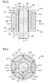
- FIG. 6 shows a longitudinal section of the permanent magnet 210 of FIG. 5 along the line VI-VI.
- the contour 223 of the permanent magnet 210 has the recess 224 in the end face 212 of the first end 211.
- the permanent magnet 202 has analogously to the second end 231 of the permanent magnet 210 has a contour which has the surface 238 for the second connection of the connecting device 772 with the permanent magnet 210 by positive engagement.
- the contour has a web projecting with respect to the end face
- the surfaces for the positive connection are not located in the recess 224 but on the projecting web.
- FIG. 7 shows a longitudinal section through a third embodiment of a rotor 700 according to the invention the permanent magnets according to the invention 210 according to the FIG. 5 having.
- This embodiment also has features based on the 3 and FIG. 4 have been described.
- the features are in the FIG. 7 provided with reference numerals consisting of the reference numerals of 3 and FIG. 4 by replacing the first digit "6" with a "7".
- the rotor 700 has the connection by positive locking at the first axial end 741 of the rotor 700 and the rotor has a second connection by positive engagement of the connecting device 772 with the end face at the second end 231 of the permanent magnet 210.
- the permanent magnets 210 are also embedded in the connector 772 by making the connector 772 by injection molding with an injection molding tool, the permanent magnets 210 concentric with their first convex portion 216 on the envelope of the rotor 700 on a rotation axis 4 extending circular line are arranged. That is, in the case of the rotor 705, the mounting of the shaft 705 is performed separately.
- the connecting device 772 has the opening 743 for the shaft 705. After attaching and embedding the permanent magnets 210 in the connector 772, the shaft 705 may be pressed through the opening 743 to frictionally secure the connector 772 to the shaft 705. Thus forces are permanently exerted on the connecting device 772.
- the end face of the first end 211 can cost-effectively have the surface 218 for the connection of the connecting device 772 to the permanent magnet 210 by adhesion.
- FIG. 8 shows a view of the third embodiment according to the FIG. 7 in which one sees along the axis of rotation 6 of the rotor 700 on the first axial end of the rotor 700.
- the features of the permanent magnets 210 of the connecting device 772 and of the shaft 705, which are not visible in this view, are indicated by dashed lines.
- FIG. 9 shows a longitudinal section through a fourth embodiment of a rotor 800 according to the invention, the inventive permanent magnets 310 according to the FIG. 10 having.
- This embodiment also has features based on the 7 and FIG. 8 have been described.
- the features are in the FIG. 9 provided with reference numerals consisting of the reference numerals of 7 and FIG. 8 by replacing the first digit "7" with an "8".
- the rotor 800 has the connection at the first axial end 841 of the rotor 800 by positive engagement, and the rotor 800 has a second connection of the connection device 872 with the end surface at the second end 331 of the permanent magnet 310.
- the rotor 800 has the second connection in a rotor section 844 between the first axial end 841 and the second axial end 842 of the rotor 800 and the rotor 800 has at least one further permanent magnet 310 between the rotor section 844 and the second axial end 842.
- a plurality of permanent magnets 310 in the axial direction 7 are successively provided with two permanent magnets 310 on the rotor 800.
- the FIG. 10 shows a cross section of the rotor 309 of FIG. 9 along the line XX.
- the connecting device 872 extends annularly in a cross section 845 of the rotor 800 adjacent to the permanent magnet 310, concentrically with the envelope 875 of the rotor 800.
- the connecting device 872 has for this purpose a ring as a connecting part 876.
- the rotor 800 according to the FIG. 10 has permanent magnets according to the invention 310 according to a fourth embodiment of a permanent magnet according to the invention 310.
- the fourth embodiment of the invention permanent magnets also has features that are based on the FIG. 1 have been described. The features are in the FIG. 9 and the FIG. 10 provided with reference numerals consisting of the reference numerals of FIG.
- the contour 323 has a recess 324 in the end face of the first end 311 of the permanent magnet 310.
- the contour 323 has a groove which is formed by the recess 324.
- the contour 323 has a boundary 309, which extends arcuately from a first point 308 of the second convex portion 317 to a second point 320 of the second convex portion 317.
- the connecting part 876 ie the ring of the connecting device 872, has a peripheral edge 877 for a positive connection with the boundary 309 of the contour 323. The connecting part 876 thus extends in the groove of two permanent magnets 310 arranged one after the other in the axial direction 7.
- the connecting part 876 is connected to a casting 878, which is the connecting device 872 has.
- the connecting part 876 is made of a steel, a carbon fiber reinforced plastic or a glass fiber reinforced plastic. The use of these materials is advantageous cost possible in a high quality in the rotor 800, since the centrifugal forces claim the material of the ring 876 to train.
- the permanent magnets 310 with the connecting part 876 can advantageously be positioned at least partially fixed in an injection molding tool and the casting 878 can be produced by injection molding with an injection molding material.
- the injection molding material comprises a plastic.
- the connecting part 876 is made of a glass fiber reinforced material or carbon fiber reinforced material
- the rotor 800 without shaft 805 can advantageously be produced inexpensively in a high quality and by pressing the shaft 805 into the opening 843 for the shaft, the connecting part 876 be biased, since the glass fiber reinforced material or carbon fiber reinforced material advantageous elastic for this is.
- a non-positive connection of the connecting device 872 with the permanent magnet 310 is advantageously inexpensive in high quality.
- FIG. 11 shows a longitudinal section through a fifth embodiment of a rotor 900 according to the invention, the inventive permanent magnets 410 according to a fifth embodiment.
- the fifth embodiment of the permanent magnet 410 also has features based on the FIG. 1 , of the 9 and FIG. 10 have been described.
- the features are in FIG. 11 provided with reference numerals or can be provided with reference numerals consisting of the reference numerals of FIG. 1 . 9 and FIG. 10 by replacing the first digit "8" with a "9” or by prefixing a "4".
- the permanent magnet 410 has, as in the fifth embodiment, a contour 473 with a groove having a rim 409 extending arcuately from the first point of the second convex portion to the second point of the second convex portion.
- the recess 424 extends with a smaller depth compared to the groove to the second convex portion of the permanent magnet 410th
- the FIG. 12 shows a cross section of the rotor 900 of FIG. 11 along the line XII-XII.
- the connecting device 972 extends annularly in its cross section 945 of the rotor 900 adjacent the permanent magnet 410, concentrically with the envelope 975 of the rotor 900.
- the connecting device in the cross section 945 of the rotor 900 has a connecting part 976, which has a peripheral edge 977 for a positive connection with the boundary 409 of the contour 423 of the permanent magnet 410.
- the connecting part 976 extends to the opening 943 for the shaft 905. In the embodiment of the FIG. 11 and FIG. 12
- the connecting part 976 extends from its peripheral edge 977 to the opening 943 disc-shaped.
- the connecting part 976 is along the opening 943 for the shaft 905 by successive Recesses 978 segmented.
- the rotor 900 can be fastened cost-effectively in a high quality with a press fit on the shaft 905 and, in addition, a centering of the permanent magnets 410 with respect to the axis of rotation 4 can advantageously be achieved.
- the connecting part 976 may be injected into the casting 978 as in the fourth embodiment of a rotor 800 according to the invention.
- FIG. 13 shows embodiments of inventive electrical machines 61, 62, 63, 64. These embodiments have features that are based on the 1 to 12 already described. These are in FIG. 13 not provided with reference numerals, but could with the reference numerals as in 1 to 12 be provided and described with the associated description.
- the electrical machines and corresponding embodiments of uses of the permanent magnets for a rotor of an electric machine according to the invention are described below with reference to an electrical machine, wherein the reference numerals of all embodiments are given.
- the description of the first embodiment with reference numeral 61 may be restricted to the reference numerals of the features of the electric machine with reference numeral 61 by deleting the reference numerals of a feature denoted second to fourth.
- the electric machine 61, 62, 63, 64 comprises a rotor 600, 700, 800, 900 and a stator 53, which in an operation of the electric machine 61, 62, 63, 64 via an air gap 54 with the rotor 600, 700, 800, 900 magnetically cooperates, wherein the rotor 600, 700, 800, 900 is rotatably mounted about the rotation axis 4.
- the rotor 600, 700, 800, 900 is fastened to the shaft 605, 705, 805, 905 and can be rotated by means of these with a first and a second bearing device 58 about the rotation axis 4 in a housing 52 of the electrical machine 61, 62, 63, 64 stored.
- the stator 53 is fixed in rotation in the housing 52 and has at least one winding 55 which extends in the axial direction 7 of the axis of rotation 4 along the air gap 54.
- the permanent magnets 10, 110, 210, 310, 410, 1010 for the rotor 600, 700, 800, 900 of the electric machine 61, 62, 63, 64 of the permanent magnets 10, 110, 210, 310, 410 , 1010 is used in the rotor 600, 700, 800, 900. This has been described in connection with the permanent magnet 10, 110, 210, 310, 410, 1010, the rotor 600, 700, 800, 900 and the electric machine 61, 62, 63, 64.
Landscapes
- Engineering & Computer Science (AREA)
- Power Engineering (AREA)
- Manufacturing & Machinery (AREA)
- Physics & Mathematics (AREA)
- Electromagnetism (AREA)
- Permanent Field Magnets Of Synchronous Machinery (AREA)
Abstract
Description
- Die Erfindung betrifft einen Permanentmagneten gemäß dem Oberbegriff des Anspruchs 1. Die Erfindung betrifft auch einen Rotor für eine elektrische Maschine, umfassend den Permanentmagneten, sowie die elektrische Maschine und eine Verwendung des Permanentmagneten für den Rotor der elektrischen Maschine.
- Ein derartiger Permanentmagnet ist aus der
CH 549 307 A - Der Erfindung liegt die Aufgabe zugrunde, einen technischen Beitrag zu einem Permanentmagneten zu leisten, bei dem kostengünstig in einer hohen Qualität eine Verbindungsvorrichtung eines Rotors oder einer elektrischen Maschine mit dem Permanentmagneten verbunden werden kann und für einen kostengünstigen Rotor oder elektrischen Maschine hoher Qualität verwendet werden kann.
- Die Aufgabe wird durch einen Permanentmagneten mit den Merkmalen des Anspruchs 1 gelöst.
- Ein erfindungsgemäßer Permanentmagnet umfasst
- einen Nord- und einen Südpol als magnetische Pole und
- Endflächen an einem ersten Ende und einem zweiten Ende des Permanentmagneten,
- wobei in einem Querschnitt des Permanentmagneten eine Magnetisierung von dem Südpol zu dem Nordpol verläuft,
- wobei der Querschnitt eine Hüllkurve mit einem ersten konvexen Abschnitt aufweist,
- wobei die magnetischen Pole bogenförmig entlang dem ersten konvexen Abschnitt verlaufen,
- wobei die Hüllkurve bikonvex linsenförmig den ersten konvexen Abschnitt und einen zweiten konvexen Abschnitt aufweist,
- wobei der Permanentmagnet entlang des zweiten konvexen Abschnitts bogenförmig verläuft,
- wobei mindestens eine der Endflächen innerhalb der Hüllkurve eine Fläche für eine Verbindung einer Verbindungsvorrichtung mit dem Permanentmagneten aufweist.
- Die Aufgabe wird auch durch einen Rotor für eine elektrische Maschine mit den Merkmalen des Anspruchs 11 gelöst.
- Ein erfindungsgemäßer Rotor für eine elektrische Maschine umfasst einen erfindungsgemäßen Permanentmagneten, wobei der Permanentmagnet sich von seinem ersten Ende zu seinem zweiten Ende parallel zu einer Drehachse erstreckt, wobei der erste konvexe Abschnitt des Permanentmagneten entlang einer Hüllkurve des Rotors angeordnet ist, wobei der Rotor die Verbindungsvorrichtung und die Verbindung zwischen der Verbindungsvorrichtung und der Fläche des Permanentmagneten aufweist.
- Die Aufgabe wird auch durch eine elektrische Maschine mit den Merkmalen des Anspruchs 14 gelöst.
- Die erfindungsgemäße elektrische Maschine umfasst einen erfindungsgemäßen Rotor und einen Stator, der in einem Betrieb der elektrischen Maschine über einen Luftspalt magnetisch zusammenwirkt, wobei der Rotor um die Drehachse drehbar gelagert ist.
- Die Aufgabe wird auch durch eine Verwendung eines Permanentmagneten nach Anspruch 15 gelöst.
- Bei einer erfindungsgemäßen Verwendung eines erfindungsgemäßen Permanentmagneten. Bei einer erfindungsgemäßen Verwendung eines erfindungsgemäßen Permanentmagneten für einen Rotor einer elektrischen Maschine wird der Permanentmagnet bei dem Rotor verwendet, der die Verbindungsvorrichtung aufweist, wobei der Rotor die Verbindung zwischen der Verbindungsvorrichtung und der Fläche des Permanentmagneten aufweist, wobei mindestens eine der Endflächen des Permanentmagneten die Fläche aufweist, und der Querschnitt des Permanentmagneten die bikonvexe linsenförmige Hüllkurve aufweist.
- Die Aufgabe wird erfindungsgemäß vorteilhaft gelöst, indem durch den Querschnitt des Permanentmagneten mit seiner bikonvexen linsenförmigen Hüllkurve die Fläche an mindestens einer Endfläche des Permanentmagneten vorteilhaft kostengünstig in einer hohen Qualität für eine Verbindung mit dem Permanentmagneten genutzt werden kann. Vorteilhaft platzsparend kann durch den erfindungsgemäßen Querschnitt und die vom Süd- zum Nordpol verlaufende Magnetisierung eine laterale Magnetisierung mit vorteilhaft geringer Menge an Magnetmaterial vorteilhaft erreicht werden. Durch die laterale Magnetisierung stellt der Permanentmagnet vorteilhaft platzsparend den Nord- und den Südpol entlang des ersten konvexen Abschnitts auf einer Seite des Permanentmagneten zur Verfügung. Vorteilhaft platzsparend können durch die zueinander bikonvexe linsenförmige Anordnung des ersten konvexen Abschnitts und des zweiten konvexen Abschnitts die Endflächen vorteilhaft große Flächen zur Verbindung einer Verbindungsvorrichtung, insbesondere einer Verbindungsvorrichtung der elektrischen Maschine, mit dem Permanentmagneten zur Verfügung stellen.
- Die mindestens eine der Endflächen kann innerhalb der Hüllkurve des Querschnitts verlaufen. So kann die Endfläche vorteilhaft kostengünstig in einer hohen Qualität hergestellt und in einer elektrischen Maschine verwendet werden, da die Endfläche nicht über die Hüllkurve hinausragt.
- Der Permanentmagnet erstreckt sich von seinem ersten Ende in einer ersten Richtung bis zu seinem zweiten Ende. Der Querschnitt des Permanentmagneten erstreckt sich in einer Ebene, die durch eine zweite Richtung und eine dritte Richtung aufgespannt sind. Die zweite Richtung und die dritte Richtung verlaufen senkrecht zu der ersten Richtung.
- Ein erfindungsgemäßer Rotor weist den weiteren Vorteil auf, dass der Rotor vorteilhaft kostengünstig in hoher Qualität mit vorteilhaft kleinen Abmessungen zur Verfügung gestellt werden kann. Die Permanentmagnete können vorteilhaft eine geringe Höhe aufweisen, wobei die Höhe als größter Abstand zwischen dem ersten und dem zweiten konvexen Abstand gemessen ist.
- Der Rotor kann mindestens zwei erfindungsgemäße Permanentmagnete aufweisen, die sich von ihrem ersten zu ihrem zweiten Ende parallel zu einer Drehachse erstrecken, wobei die ersten konvexen Abschnitte der Permanentmagnete an der Hüllkurve des Rotors auf einer zu der Drehachse konzentrisch verlaufenden Kreislinie angeordnet sind, wobei der Rotor mindestens die Verbindungsvorrichtung aufweist und die Verbindungen zwischen der mindestens einen Verbindungsvorrichtung und der Fläche der Permanentmagneten aufweist. So kann eine gleichmäßigere Drehbewegung des Rotors um die Drehachse vorteilhaft erreicht werden.
- Ein Nordpol eines Permanentmagneten kann entlang der Hüllkurve des Rotors neben dem Nordpol des an der Hüllkurve des Rotors nächstgelegenen Permanentmagneten vorhanden sein. So kann vorteilhaft kostengünstig in einer hohen Qualität ein magnetischer Pol eines erfindungsgemäßen Rotors die beiden Nordpole aufweisen. Vorteilhaft kann hierbei der Abstand zwischen dem Permanentmagneten und seinem nächstgelegenen Permanentmagneten nicht dem Abstand des Nordpols und des Südpols von ein und demselben Permanentmagneten entsprechen.
- Eine erfindungsgemäße elektrische Maschine weist den weiteren Vorteil auf, dass die elektrische Maschine vorteilhaft kostengünstig in einer hohen Qualität mit vorteilhaft kleiner Abmessung zur Verfügung gestellt werden kann. Es kann vorteilhaft platzsparend ein erfindungsgemäßer Permanentmagnet in der elektrischen Maschine an einem erfindungsgemäßen Rotor durch die Verbindung befestigt werden und dabei eine vorteilhaft hohe Luftspalt-Induktion im Luftspalt der erfindungsgemäßen elektrischen Maschine vorteilhaft erreicht werden.
- Beispielsweise könnte dadurch auf eine Bandagierung des gesamten Rotors vorteilhaft verzichtet werden. In diesem Fall sind die magnetischen Pole der Permanentmagnete im Luftspalt nicht vollständig, insbesondere überhaupt nicht, mit einer Verbindungsvorrichtung, z.B. einer Bandage, bedeckt. So kann die Luftspalt-Induktion weiterhin vorteilhaft erhöht werden oder die Abmessung der elektrischen Maschine vorteilhaft verkleinert werden.
- Ein erfindungsgemäßer Rotor kann an einer Welle befestigt in einer erfindungsgemäßen elektrischen Maschine mithilfe einer ersten Lagervorrichtung und einer zweiten Lagervorrichtung um die Drehachse drehbar gelagert werden.
- In einem Betrieb einer erfindungsgemäßen elektrischen Maschine mit einem erfindungsgemäßen Rotor als Generator wird der Rotor durch mechanische Energie in eine Drehung um die Drehachse versetzt. Durch das magnetische Zusammenwirken zwischen magnetischen Polen des Rotors und des Stator über einen Luftspalt kann die mechanische Energie in elektrische Energie umgewandelt werden. Die elektrische Energie kann an mindestens einer Wicklung, die am Stator befestigt ist und zu einer Bildung der magnetischen Pole des Stators beiträgt, durch Anschließen eines elektrischen Verbrauchers entnommen werden.
- Bei einem Betrieb einer erfindungsgemäßen elektrischen Maschine mit einem erfindungsgemäßen Rotor als Motor wird über die mindestens eine Wicklung elektrische Energie zugeführt und durch das magnetische Zusammenwirken zwischen den magnetischen Polen des Stators und eines erfindungsgemäßen Rotors über den Luftspalt elektrische Energie in mechanische Energie umgewandelt. Dabei wird ein Drehmoment erzeugt, dass den Rotor in Drehung um die Drehachse versetzen kann und es kann an der Welle mechanische Energie an einen mechanischen Verbraucher in Form einer Drehbewegung abgegeben werden.
- Eine erfindungsgemäße Verwendung des Permanentmagneten weist den weiteren Vorteil auf, dass der Permanentmagnet kostengünstig in einer hohen Qualität mit vorteilhaft kleinen Abmessungen angeliefert werden kann. So wird Transportvolumen für den Permanentmagneten und für die dafür notwendigen Sicherheitsvorkehrungen vorteilhaft eingespart.
- Vorteilhafte Ausgestaltungen der Erfindung sind in den abhängigen Ansprüchen angegeben. Es wird hierbei ein technischer Beitrag zur vorteilhaften Ausgestaltung eines erfindungsgemäßen Permanentmagneten geleistet, bei dem kostengünstig in einer hohen Qualität eine Verbindungsvorrichtung eines Rotors oder einer elektrischen Maschine mit dem Permanentmagneten verbunden werden kann und für einen kostengünstigen Rotor oder elektrischen Maschine hoher Qualität verwendet werden kann.
- So ist eine Ausgestaltung eines erfindungsgemäßen Permanentmagneten vorteilhaft, bei der die Endfläche des ersten Endes die Fläche zumindest für die Verbindung der Verbindungsvorrichtung mit dem Permanentmagneten durch Stoffschluss aufweist. So kann der Permanentmagnet vorteilhaft über eine Ebene stoffschlüssig mit der Verbindungsvorrichtung verbunden werden. Eine Ebene kann mit vorteilhaft einfachen Werkzeugen mit vorteilhaft einfachen Bewegungsabläufen herstellgestellt werden.
- Es kann die Fläche des Permanentmagneten unbearbeitet sein. So kann unter Verzicht auf eine Beschichtung kostengünstig eine qualitativ hochwertige Verbindung vorteilhaft erreicht werden, die die Übertragung von großen Kräften von einem erfindungsgemäßen Permanentmagneten auf eine Verbindungsvorrichtung vorteilhaft ermöglicht, da eine stoffschlüssige Schicht zwischen der Verbindungsvorrichtung und dem Permanentmagneten an der Fläche aufgrund ihrer Rauigkeit besser haftet. Es kann z.B. hierfür nach dem Sintern des Permanentmagneten auf eine Nachbearbeitung der Fläche für die Verbindung vorteilhaft verzichtet werden.
- Die Fläche des Permanentmagneten kann eine Beschichtung aufweisen. So kann kostengünstig eine qualitativ hochwertige Verbindung vorteilhaft erreicht werden, die eine Übertragung von großen Kräften durch Stoffschluss zwischen der Verbindungsvorrichtung und der Beschichtung und einem erfindungsgemäßen Permanentmagneten vorteilhaft erreicht. Hierbei kann die Fläche vor einem Aufbringen der Beschichtung auf dem Permanentmagneten unbearbeitet sein oder bearbeitet sein.
- In einer weiteren vorteilhaften Ausgestaltung eines erfindungsgemäßen Permanentmagneten weist die Endfläche des ersten Endes eine Kontur auf, die die Fläche für die Verbindung der Verbindungsvorrichtung mit dem Permanentmagneten durch Formschluss aufweist. So kann an der Endfläche die Kontur vorteilhaft hergestellt werden, da diese durch die bikonvexe linsenförmige Hüllkurve und den bogenförmigen Verlauf der Magnetisierung eine vorteilhaft große Fläche aufweisen kann.
- In einer weiteren vorteilhaften Ausgestaltung eines erfindungsgemäßen Permanentmagneten weist die Kontur eine Ausnehmung in der Endfläche des ersten Endes auf. Aufgrund der vorteilhaft großen Fläche kann trotz der Ausnehmung noch eine vorteilhafte Berandung der Ausnehmung erreicht werden und Materialausbrüche an den Permanentmagneten vorteilhaft vermieden werden.
- Die Kontur kann eine Nut aufweisen. So können vorteilhaft parallel zum Querschnitt auf dem Permanentmagnet wirkende Kraftkomponenten vorteilhaft auf die Fläche verteilt entsprechend dem Verlauf der Nut vorteilhaft aufgenommen werden.
- In einer weiteren vorteilhaften Ausgestaltung eines erfindungsgemäßen Permanentmagneten weist die Kontur einen gegenüber der Endfläche hervorstehenden Steg auf. Es kann so zum Verbinden mit der Verbindungsvorrichtung der Steg vorteilhaft einfach eingegossen werden.
- In einer weiteren vorteilhaften Ausgestaltung eines erfindungsgemäßen Permanentmagneten weist die Kontur eine kreisrunde Berandung auf. Vorteilhaft kann durch die kreisförmige Berandung die Fläche groß ausgeführt werden.
- In einer weiteren vorteilhaften Ausgestaltung eines erfindungsgemäßen Permanentmagneten weist die Kontur eine Berandung auf, die sich bogenförmig von einem ersten Punkt des zweiten konvexen Abschnitts zu einem zweiten Punkt des zweiten konvexen Abschnitts erstreckt. Es kann so vorteilhaft eine parallel zu dem Querschnitt auf dem Permanentmagneten relativ zu der Verbindungsvorrichtung wirkende Kraftkomponente durch die Berandung aufgenommen werden. Insbesondere ist dies bei einem erfindungsgemäßen Rotor vorteilhaft, bei dem Kräfte in radialer Richtung wirken.
- Es kann die Verbindungsvorrichtung ein Verbindungsteil aufweisen, das einen umlaufenden Rand für eine formschlüssige Verbindung mit der Berandung der Kontur aufweist. Die Verbindung der Verbindungsvorrichtung mit dem Permanentmagneten durch Formschluss kann so diese formschlüssige Verbindung aufweisen. So können vorteilhaft, insbesondere bei einem erfindungsgemäßen Rotor, durch den umlaufenden Rand hohe Kräfte von der Berandung aufgenommen werden, da der umlaufende Rand keinen Anfang und keine Ende aufweist und so beim Einwirken der Kräfte auf dem Rand diese auf dem gesamten umlaufende Rand verteilt werden.
- In einer weiteren vorteilhaften Ausgestaltung eines erfindungsgemäßen Permanentmagneten weist der Permanentmagnet zwischen dem Nord- und dem Südpol an dem ersten konvexen Abschnitt eine Ausnehmung auf. So kann vorteilhaft bei einer erfindungsgemäßen elektrischen Maschine die dem Luftspalt zugewandte Oberfläche des Rotors eine Ausnehmung zwischen dem Nord- und dem Südpol des Permanentmagneten aufweisen.
- In einer weiteren vorteilhaften Ausgestaltung eines erfindungsgemäßen Permanentmagneten verläuft der Permanentmagnet zwischen dem Nord- und dem Südpol entlang dem ersten konvexen Abschnitt. So kann bei einer erfindungsgemäßen Maschine vorteilhaft die dem Luftspalt zugewandte Oberfläche des Rotors zwischen dem Nord- und dem Südpol des Permanentmagneten eine durchgehende Oberfläche aufweisen.
- In einer weiteren vorteilhaften Ausgestaltung eines erfindungsgemäßen Permanentmagneten ist der Permanentmagnet ein gesinterter Permanentmagnet. Es kann vorteilhaft ein erfindungsgemäßer Permanentmagnet mit hoher Magnetkraft für eine erfindungsgemäße Verwendung verwendet werden, insbesondere kann er als Bestandteil eines erfindungsgemäßen Rotors oder einer erfindungsgemäßen elektrischen Maschine vorhanden sein. Es kann eine hohe Luftspaltinduktion platzsparend durch eine hohe Magnetkraft mit einer zuverlässigen Verbindung bzw. Verbindungsmöglichkeit des Permanentmagneten vorteilhaft erreicht werden.
- In einer weiteren vorteilhaften Ausgestaltung eines erfindungsgemäßen Rotors weist der Rotor die Verbindung an einem ersten axialen Ende des Rotors auf und der Rotor weist eine zweite Verbindung der Verbindungsvorrichtung mit der Endfläche an dem zweiten Ende des Permanentmagneten auf. So können die Permanentmagnete durch eine Verbindung an ihren beiden Endflächen mit dem Rotor vorteilhaft verbunden und damit vorvorteilhaft befestigt, werden, insbesondere vorteilhaft innerhalb der Hüllkurve des Rotors.
- In einer weiteren vorteilhaften Ausgestaltung eines erfindungsgemäßen Rotors weist der Rotor die zweite Verbindung in einem Rotorabschnitt zwischen dem ersten und einem zweiten axialen Ende des Rotors auf und der Rotor weist zwischen dem Rotorabschnitt und dem zweiten axialen Ende mindestens einen weiteren Permanentmagneten auf. Es können so vorteilhaft mehrere Permanentmagnete in axialer Richtung hintereinander an dem Rotor befestigt werden.
- In einer weiteren vorteilhaften Ausgestaltung eines erfindungsgemäßen Rotors erstreckt sich die Verbindungsvorrichtung in einem Querschnitt des Rotors an den Permanentmagneten angrenzend konzentrisch zur Hüllkurve des Rotors ringförmig. Es kann so eine vorteilhaft gleichmäßige Verteilung von Fliehkräften in einem Betrieb der elektrischen Maschine auf die Verbindungsvorrichtung vorteilhaft erreicht werden und gleichzeitig vorteilhaft bei mehreren Permanentmagneten in axialer Richtung hintereinander geringe, im Idealfall keine, Unterbrechung der Oberfläche zwischen hintereinander angeordneten Permanentmagneten erreicht werden.
- In einer weiteren vorteilhaften Ausgestaltung eines erfindungsgemäßen Rotors ist der Permanentmagnet in der Verbindungvorrichtung eingebettet. So können vorteilhaft die Anforderungen an die Maßhaltigkeit des Permanentmagneten in seinen Abmessungen vorteilhaft gering sein, da die Verbindungsvorrichtung die Lücken, die durch eine fehlende Maßhaltigkeit des Permanentmagneten entstehen, ausfüllt. So kann z.B. auf eine mechanische Nachbearbeitung eines Permanentmagneten nach dem Sintern vorteilhaft verzichtet werden.
- Vorteilhafte Ausgestaltungen erfindungsgemäßer Permanentmagnete, erfindungsgemäßer Rotoren sowie erfindungsgemäßer elektrischer Maschinen und erfindungsgemäßer Verwendungen ergeben sich vorteilhaft durch Kombination einiger oder mehrerer beschriebener Merkmale. Die oben beschriebenen Eigenschaften, Merkmale und Vorteile dieser Erfindung sowie die Art und Weise, wie diese erreicht werden, werden klarer und deutlicher verständlich im Zusammenhang mit der nun folgenden Beschreibung der Ausführungsbeispiele, die anhand der Figuren näher erläutert werden.
- Es zeigen:
- FIG 1
- ein erstes Ausführungsbeispiel eines erfindungsgemäßen Permanentmagneten,
- FIG 2
- eine Ansicht eines zweiten Ausführungsbeispiels eines erfindungsgemäßen Permanentmagneten, bei der man auf eine Endfläche sieht,
- FIG 3
- einen Längsschnitt durch ein erstes Ausführungsbeispiel eines erfindungsgemäßen Rotors,
- FIG 4
- einen Querschnitt des Rotors der
FIG 3 entlang der Linie IV-IV, - FIG 5
- eine Ansicht eines dritten Ausführungsbeispiels eines erfindungsgemäßen Permanentmagneten, bei der man auf eine Endfläche sieht,
- FIG 6
- einen Längsschnitt des Permanentmagneten der
FIG 5 entlang der Linie VI-VI, - FIG 7
- einen Längsschnitt durch ein drittes Ausführungsbeispiel eines erfindungsgemäßen Rotors, der erfindungsgemäße Permanentmagnete gemäß der
FIG 5 aufweist, - FIG 8
- eine Ansicht des dritten Ausführungsbeispiels gemäß der
FIG 7 , bei der man entlang einer Drehachse des Rotors auf ein erstes axiale Ende des Rotors sieht, - FIG 9
- einen Längsschnitt durch ein viertes Ausführungsbeispiel eines erfindungsgemäßen Rotors, der erfindungsgemäße Permanentmagnete gemäß der
FIG 10 aufweist, - FIG 10
- einen Querschnitt des Rotors der
FIG 9 entlang der Linie X-X, - FIG 11
- einen Längsschnitt durch ein fünftes Ausführungsbeispiel eines erfindungsgemäßen Rotors, der erfindungsgemäße Permanentmagnete gemäß einem fünften Ausführungsbeispiel aufweist,
- FIG 12
- einen Querschnitt des Rotors der
FIG 11 entlang der Linie XII-XII, - FIG 13
- Ausführungsbeispiele erfindungsgemäßer elektrischer Maschinen.
-
FIG 1 zeigt ein erstes Ausführungsbeispiel eines erfindungsgemäßen Permanentmagneten 10 der einen Nordpol 21 und einen Südpol 22 als magnetische Pole umfasst. Des Weiteren umfasst der Permanentmagnet 10 die Endflächen 12, 32 an einem ersten Ende 11 und an einem zweiten Ende 32. In einem Querschnitt 13 des Permanentmagneten 10 verläuft eine Magnetisierung 14 von dem Südpol 22 zu dem Nordpol 21, wobei der Querschnitt 13 eine Hüllkurve 15 mit einem ersten konvexen Abschnitt 16 aufweist und die magnetischen Pole bogenförmig entlang des ersten konvexen Abschnitts 16 verlaufen. Durch die laterale Magnetisierung 14 stellt der Permanentmagnet 10 den Nord- 21 und den Südpol 22 entlang des ersten konvexen Abschnitts 16 auf einer Seite des Permanentmagneten 10 zur Verfügung. In dem Ausführungsbeispiel gemäß derFIG 1 weist die Endfläche 12 an dem ersten Ende 11 den Querschnitt 13 des Permanentmagneten 10 auf. Der Permanentmagnet 10 erstreckt sich von seinem ersten Ende 11 in einer ersten Richtung 1 bis zu seinem zweiten Ende 31, wobei alle Querschnitte entlang der ersten Richtung 1 gleiche Hüllkurven 15 aufweisen. Die Hüllkurve 15 weist bikonvex linsenförmig den ersten konvexen Abschnitt 16 und einen zweiten konvexen Abschnitt 17 auf, wobei der Permanentmagnet 10 entlang des zweiten konvexen Abschnitts 17 bogenförmig verläuft. Mindestens eine der Endflächen 12 weist innerhalb der Hüllkurve 15 eine Fläche 18 für eine Verbindung 670 einer Verbindungsvorrichtung 672 mit dem Permanentmagneten 10 auf. Eine Höhe des Permanentmagneten 10 ist als größter Abstand zwischen dem ersten konvexen Abschnitt 16 und dem zweiten konvexen Abschnitt 17 gemessen. Der Querschnitt 13 des Permanentmagneten 10 erstreckt sich in einer Ebene, die durch eine zweite Richtung 2 und eine dritte Richtung 3 aufgespannt sind. Die zweite Richtung 2 und die dritte Richtung 3 verlaufen senkrecht zu der ersten Richtung 1. Die Endfläche 12 des ersten Endes 11 weist die Fläche 18 zumindest für die Verbindung 670 der Verbindungsvorrichtung 672 mit dem Permanentmagneten 10 durch Stoffschluss auf. In dem Ausführungsbeispiel gemäß derFIG 1 wird die Endfläche 12 an dem ersten Ende 11 durch die Fläche 18 gebildet, die eine Ebene ist. Der Permanentmagnet 10 verläuft zwischen dem Nordpol 21 und dem Südpol 22 entlang dem ersten konvexen Abschnitt 16. Der Permanentmagnet 10 ist ein gesinterter Permanentmagnet. -
FIG 2 zeigt eine Ansicht eines zweiten Ausführungsbeispiels eines erfindungsgemäßen Permanentmagneten 110, bei der man auf eine Endfläche 112 sieht. Dieses Ausführungsbeispiel weist Merkmale auf, die anhand derFIG 1 beschrieben wurden. Die Merkmale sind inFIG 2 größtenteils mit Bezugszeichen versehen, die aus den Bezugszeichen derFIG 1 durch Voranstellen einer "1" entstanden ist. So ist z. B. die Beschreibung zu dem zweiten konvexen Abschnitt 17 derFIG 1 entsprechend auf einen zweiten konvexen Abschnitt 117 derFIG 2 zu übertragen. Auf die unterschiedlichen Merkmale des Permanentmagneten 110 gemäßFIG 2 gegenüber dem Permanentmagneten 10 gemäßFIG 1 wird nachfolgend eingegangen. Der Permanentmagnet 110 gemäß derFIG 2 weist zwischen dem Nordpol 121 und dem Südpol 122 an dem ersten konvexen Abschnitt 116 eine Ausnehmung 119 auf. Die Fläche 118 des Permanentmagneten 110 ist unbearbeitet. Der Permanentmagnet 110 wurde damit nach dessen Sintern an der Fläche 118, d. h. an der Endfläche 112 nicht mechanisch bearbeitet. - Die
FIG 3 zeigt einen Längsschnitt durch ein erstes Ausführungsbeispiel eines erfindungsgemäßen Rotors 600, der einen Permanentmagneten 1010 umfasst, wobei der Permanentmagnet 1010 sich von seinem ersten Ende 1011 zu seinem zweiten Ende 1031 parallel zu einer Drehachse 4 erstreckt, wobei der Rotor 600 die Verbindungsvorrichtung 672 und die Verbindung 670 zwischen der Verbindungsvorrichtung 672 und der Fläche 1018 des Permanentmagneten 1010 aufweist. Der Permanentmagnet 1010 gemäß derFIG 3 weist die größtenteils mit Bezugszeichen versehenen Merkmale des Permanentmagneten 10 gemäß derFIG 1 auf, wobei den Bezugszeichen derFIG 1 eine "10" vorangestellt wurde. Der Permanentmagnet 1010 gemäß derFIG 3 weist an den Flächen 1018, 1038 eine Beschichtung auf. Die Verbindungsvorrichtung 672 weist einen Kunststoff auf, der die Verbindung mit dem Permanentmagneten 1010 durch Stoffschluss mit dessen Beschichtung ausbildet. Zur Ausbildung der Verbindungen 670, 671 der Verbindungsvorrichtung 672 mit den Flächen 1018, 1038 der Endflächen an dem ersten Ende 1011 und dem zweiten Ende 1031 des Permanentmagneten 1010 wird der Kunststoff der Verbindungsvorrichtung 673 erwärmt, so dass sich die Verbindungen 670, 671 durch Stoffschluss ausbilden. Der Rotor 600 weist die Verbindung 1018 an einem ersten axialen Ende 641 des Rotors 600 auf und der Rotor 600 weist die zweite Verbindung 671 der Verbindungsvorrichtung mit der Endfläche an dem zweiten Ende 1031 des Permanentmagneten 1010 auf. - Der Rotor 600 weist eine Welle 605 auf, die sich entlang der Drehachse 4 erstreckt. Die Welle 605 weist eine Rändelung 606 auf, die sich in einer Richtung parallel zu der Drehachse 4 abschnittsweise entlang der Verbindungsvorrichtung 672 erstreckt. Eine Befestigung der Permanentmagnete 1010 an der Welle 605 über die Verbindungsvorrichtung 672 wird durch Spritzgießen hergestellt. Hierbei wird die Welle 605 und die Permanentmagnete 1010 entsprechend positioniert und der Kunststoff für die Verbindungsvorrichtung 672 durch Spritzgießen zwischen den Permanentmagneten 1010 und der Welle 605 und an dem ersten und zweitem Ende 1011, 1031 der Permanentmagneten 1010 angebracht. Hierbei bilden sich die erste Verbindung 1018 und die zweite Verbindung 1038 an den Endflächen der Permanentmagnete 1010 durch Stoffschluss aus. Die Permanentmagnete 1010 sind dabei in der Verbindungsvorrichtung 772 eingebettet. Des Weiteren bildet sich zwischen der Welle 605 und der Verbindungsvorrichtung 672 eine stoffschlüssige Verbindung und durch die Rändelung 606 der Welle eine formschlüssige Verbindung auf. Die Endflächen an dem ersten und dem zweiten Ende 1011, 1031 weisen die Flächen 1018, 1038 für die Verbindungen 670, 671 der Verbindungsvorrichtung 672 mit dem Permanentmagneten 1010 innerhalb der Hüllkurve 1015 des Querschnitts der Permanentmagnete 1010 auf. Durch die Befestigung der Permanentmagnete 1010 an den Flächen 1018, 1038 kann vorteilhaft kostengünstig in einer hohen Qualität die Verbindungsvorrichtung 672 gleichzeitig als Anschläge 673, 674 für die Lager einer ersten und zweiten Lagervorrichtung 58 einer elektrischen Maschine 61 mit dem Rotor 600 dienen.
- Die
FIG 4 zeigt einen Querschnitt des Rotors 600 derFIG 3 entlang der Linie IV-IV. Der Rotor 600 umfasst einen Permanentmagneten 1010, wobei der erste konvexe Abschnitt 1016 des Permanentmagneten 1010 entlang einer Hüllkurve 675 des Rotors 600 angeordnet ist. Der Rotor 600 weist mindestens zwei Permanentmagnete 1016 auf, die sich von ihrem ersten 1011 zu ihrem zweiten Ende 1031 parallel zu der Drehachse 4 erstrecken, wobei die ersten konvexen Abschnitte 1016 der Permanentmagnete 1010 an der Hüllkurve 675 des Rotors 600 auf einer zu der Drehachse 4 konzentrisch verlaufenden Kreislinie angeordnet sind. In derFIG 4 ist die Kreislinie nicht von der Hüllkurve 675 des Rotors 600 unterscheidbar, da diese die Kreislinie zumindest aus Sicht der bildlichen Darstellung vollständig bedeckt und somit die Kreislinie in derFIG 4 identisch zu der Hüllkurve 675 des Rotors 600 ist. Ein Nordpol eines Permanentmagneten 1010 ist entlang der Hüllkurve 675 des Rotors 600 neben dem Nordpol des auf der Hüllkurve 675 des Rotors 600 nächst gelegenen Permanentmagneten 1010 vorhanden. - Die
FIG 5 zeigt eine Ansicht eines dritten Ausführbeispiels eines erfindungsgemäßen Permanentmagneten 210, bei der man auf eine Endfläche 212 sieht. Dieses Ausführungsbeispiel weist Merkmale auf, die anhand derFIG 1 beschrieben wurden. Die Merkmale sind inFIG 5 größtenteils mit Bezugszeichen versehen, die aus den Bezugszeichen derFIG 1 durch Voranstellen einer "2" entstanden sind. Die Endfläche 212 des ersten Endes des Permanentmagneten 210 weist eine Kontur 223 auf, die die Fläche 218 für die Verbindung der Verbindungsvorrichtung 772 mit dem Permanentmagneten 210 durch Formschluss aufweist. Die Kontur 223 weist eine kreisrunde Berandung 225 auf, an der sich in einer Ausnehmung 224 die Fläche 218 erstreckt. - Die
FIG 6 zeigt einen Längsschnitt des Permanentmagneten 210 derFIG 5 entlang der Linie VI-VI. Die Kontur 223 des Permanentmagneten 210 weist in der Endfläche 212 des ersten Endes 211 die Ausnehmung 224 auf. Der Permanentmagnet 202 weist analog dazu an den zweiten Ende 231 des Permanentmagneten 210 eine Kontur auf, die die Fläche 238 für die zweite Verbindung der Verbindungsvorrichtung 772 mit dem Permanentmagneten 210 durch Formschluss aufweist. Bei einem weiteren Ausführungsbeispiel eines erfindungsgemäßen Permanentmagneten, bei dem die Kontur einem gegenüber der Endfläche hervorstehenden Steg aufweist, befinden sich die Flächen für die formschlüssige Verbindung nicht in der Ausnehmung 224, sondern an dem hervorstehenden Steg. -
FIG 7 zeigt einen Längsschnitt durch ein drittes Ausführungsbeispiel eines erfindungsgemäßen Rotors 700 der erfindungsgemäße Permanentmagnete 210 gemäß derFIG 5 aufweist. Dieses Ausführungsbeispiel weist auch Merkmale auf, die anhand derFIG 3 und FIG 4 beschrieben wurden. Die Merkmale sind in derFIG 7 mit Bezugszeichen versehen, die aus den Bezugszeichen derFIG 3 und FIG 4 durch Ersetzen der ersten Ziffer "6" durch eine "7" entstanden sind. Der Rotor 700 weist die Verbindung durch Formschluss an dem ersten axialen Ende 741 des Rotors 700 auf und der Rotor weist eine zweite Verbindung durch Formschluss der Verbindungsvorrichtung 772 mit der Endfläche an dem zweiten Ende 231 des Permanentmagneten 210 auf. Bei dem Rotor 700 sind die Permanentmagnete 210 ebenfalls in der Verbindungsvorrichtung 772 eingebettet, indem die Verbindungsvorrichtung 772 durch Spritzgießen mit einem Spritzgusswerkzeug hergestellt wird, wobei die Permanentmagnete 210 mit ihrem ersten konvexen Abschnitt 216 an der Hüllkurve des Rotors 700 auf einer zu der Drehachse 4 konzentrisch verlaufenden Kreislinie angeordnet sind. Das heißt, dass bei dem Rotor 705 die Montage der Welle 705 separat erfolgt. Die Verbindungsvorrichtung 772 weist die Öffnung 743 für die Welle 705 auf. Nach dem Befestigen und Einbetten der Permanentmagnete 210 in die Verbindungsvorrichtung 772 kann die Welle 705 durch die Öffnung 743 gepresst werden, um die Verbindungsvorrichtung 772 kraftschlüssig an der Welle 705 zu befestigen. So werden dauerhaft Kräfte auf die Verbindungsvorrichtung 772 ausgeübt. Diese können vorteilhaft kostengünstig in einer hohen Qualität zusätzlich für die Verbindungen der Verbindungsvorrichtung 772 mit dem Permanentmagneten 210 durch Kraftschluss verwendet werden. So kann vorteilhaft kostengünstig in einer hohen Qualität die Endfläche des ersten Endes 211 die Fläche 218 auch für die Verbindung der Verbindungsvorrichtung 772 mit dem Permanentmagneten 210 durch Kraftschluss aufweisen. -
FIG 8 zeigt eine Ansicht des dritten Ausführungsbeispiel gemäß derFIG 7 , bei der man entlang der Drehachse 6 des Rotors 700 auf das erste axiale Ende des Rotors 700 sieht. In derFIG 8 sind strichliert die in dieser Ansicht nicht sichtbaren Merkmale der Permanentmagneten 210 der Verbindungsvorrichtung 772 und der Welle 705 eingezeichnet. - Die
FIG 9 zeigt einen Längsschnitt durch ein viertes Ausführungsbeispiel eines erfindungsgemäßen Rotors 800, der erfindungsgemäße Permanentmagnete 310 gemäß derFIG 10 aufweist. Dieses Ausführungsbeispiel weist auch Merkmale auf, die anhand derFIG 7 und FIG 8 beschrieben wurden. Die Merkmale sind in derFIG 9 mit Bezugszeichen versehen, die aus den Bezugszeichen derFIG 7 und FIG 8 durch Ersetzen der ersten Ziffer "7" durch eine "8" entstanden sind. Der Rotor 800 weist die Verbindung an dem ersten axialen Ende 841 des Rotors 800 durch Formschluss auf und der Rotor 800 weist eine zweite Verbindung der Verbindungsvorrichtung 872 mit der Endfläche an dem zweiten Ende 331 des Permanentmagneten 310 auf. Der Rotor 800 weist die zweite Verbindung in einem Rotorabschnitt 844 zwischen dem ersten axialen Ende 841 und dem zweiten axialen Ende 842 des Rotors 800 auf und der Rotor 800 weist zwischen dem Rotorabschnitt 844 und dem zweiten axialen Ende 842 mindestens einen weiteren Permanentmagneten 310 auf. An dem Rotor 800 sind somit mehrere Permanentmagnete 310 in der axialen Richtung 7 hintereinander zwei Permanentmagnete 310 auf. - Die
FIG 10 zeigt einen Querschnitt des Rotors 309 derFIG 9 entlang der Linie X-X. Die Verbindungsvorrichtung 872 erstreckt sich in einem Querschnitt 845 des Rotors 800 an den Permanentmagneten 310 angrenzend konzentrisch zur Hüllkurve 875 des Rotors 800 ringförmig. Die Verbindungsvorrichtung 872 weist hierfür einen Ring als Verbindungsteil 876 auf. Der Rotor 800 gemäß derFIG 10 weist erfindungsgemäße Permanentmagnete 310 gemäß einem vierten Ausführungsbeispiel eines erfindungsgemäßen Permanentmagneten 310. Das vierte Ausführungsbeispiel erfindungsgemäße Permanentmagnete weist auch Merkmale auf, die anhand derFIG 1 beschrieben wurden. Die Merkmale sind in derFIG 9 und derFIG 10 mit Bezugszeichen versehen, die aus den Bezugszeichen derFIG 1 durch Ersetzen der ersten Ziffer in "1" durch eine "3" entstanden sind. Die Kontur 323 weist eine Ausnehmung 324 in der Endfläche des ersten Endes 311 des Permanentmagneten 310 auf. Die Kontur 323 weist eine Nut auf, die durch die Ausnehmung 324 gebildet ist. Die Kontur 323 weist eine Berandung 309 auf, die sich bogenförmig von einem ersten Punkt 308 des zweiten konvexen Abschnitts 317 zu einem zweiten Punkt 320 des zweiten konvexen Abschnitts 317 erstreckt. Das Verbindungsteil 876, d. h. der Ring der Verbindungsvorrichtung 872, weist einen umlaufenden Rand 877 für eine formschlüssige Verbindung mit der Berandung 309 der Kontur 323 auf. Das Verbindungsteil 876 verläuft so in der Nut von zwei in der axialen Richtung 7 hintereinander angeordneten Permanentmagneten 310. Zwischen einem Permanentmagneten 310 und des ihm auf der Hüllkurve 875 des Rotors 800 nächstgelegenen Permanentmagneten 310 ist das Verbindungsteil 876 mit einem Gussteil 878 verbunden, welches die Verbindungsvorrichtung 872 aufweist. Damit die zulässigen Fliehkräfte in einem Betrieb des Rotors 800 durch die Festigkeit des Rings hohe Werte ohne Schädigung des Rotors 800 vorteilhaft annehmen kann, ist das Verbindungsteil 876 aus einem Stahl, einem Karbonfaser verstärkten Kunststoff oder einem Glasfaser verstärkten Kunststoff. Der Einsatz dieser Materialien ist vorteilhaft kostengünstig in einer hohen Qualität bei dem Rotor 800 möglich, da die Fliehkräfte das Material des Rings 876 auf Zug beanspruchen. Bei einer Herstellung des Rotors 800 können die Permanentmagnete 310 mit dem Verbindungsteil 876 vorteilhaft zumindest teilweise fixiert in einem Spritzgusswerkzeug positioniert werden und das Gussteil 878 durch Spritzgießen mit einem Spritzgussmaterial hergestellt werden. Das Spritzgussmaterial weist einen Kunststoff auf. Bei einem Ausführungsbeispiel des Rotors 800, bei dem das Verbindungsteil 876 aus einem Glasfaser verstärkten Material oder Karbonfaser verstärkten Material ist, kann vorteilhaft kostengünstig in einer hohen Qualität der Rotor 800 ohne Welle 805 hergestellt werden und durch das Einpressen der Welle 805 in die Öffnung 843 für die Welle das Verbindungsteil 876 vorgespannt werden, da das Glasfaser verstärkten Material oder Karbonfaser verstärkten Material vorteilhaft elastisch hierfür ist. So ist vorteilhaft kostengünstig in einer hohen Qualität auch eine kraftschlüssige Verbindung der Verbindungsvorrichtung 872 mit dem Permanentmagneten 310 vorhanden. - Die
FIG 11 zeigt einen Längsschnitt durch ein fünftes Ausführungsbeispiel eines erfindungsgemäßen Rotors 900, der erfindungsgemäße Permanentmagnete 410 gemäß einem fünften Ausführungsbeispiel aufweist. Das fünfte Ausführungsbeispiel des Permanentmagneten 410 weist auch Merkmale auf, die anhand derFIG 1 , derFIG 9 und FIG 10 beschrieben wurden. Die Merkmale sind inFIG 11 mit Bezugszeichen versehen bzw. können mit Bezugszeichen versehen werden, die aus den Bezugszeichen derFIG 1 ,FIG 9 und FIG 10 durch Ersetzen der ersten Ziffer "8" durch eine "9" entstanden sind bzw. durch Voranstellen einer "4". Der Permanentmagnet 410 weist wie bei dem fünften Ausführungsbeispiel eine Kontur 473 mit einer Nut auf, die eine Berandung 409 aufweist, die sich bogenförmig von dem ersten Punkt des zweiten konvexen Abschnitts zum zweiten Punkt des zweiten konvexen Abschnitts erstreckt. Zusätzlich erstreckt sich die Ausnehmung 424 mit einer im Vergleich zu der Nut geringeren Tiefe bis zum zweiten konvexen Abschnitt des Permanentmagneten 410. - Die
FIG 12 zeigt einen Querschnitt des Rotors 900 derFIG 11 entlang der Linie XII-XII. Die Verbindungsvorrichtung 972 erstreckt sich in ihrem Querschnitt 945 des Rotors 900 an den Permanentmagneten 410 angrenzend konzentrisch zur Hüllkurve 975 des Rotors 900 ringförmig. Hierzu weist die Verbindungsvorrichtung in dem Querschnitt 945 des Rotors 900 ein Verbindungsteil 976 auf, das einen umlaufenden Rand 977 für eine formschlüssige Verbindung mit der Berandung 409 der Kontur 423 des Permanentmagneten 410 aufweist. Das Verbindungsteil 976 erstreckt sich bis zu der Öffnung 943 für die Welle 905. In dem Ausführungsbeispiel derFIG 11 und FIG 12 erstreckt sich das Verbindungsteil 976 von seinem umlaufenden Rand 977 bis zu der Öffnung 943 scheibenförmig. Das Verbindungsteil 976 ist entlang der Öffnung 943 für die Welle 905 durch aufeinanderfolgende Ausnehmungen 978 segmentiert. So kann vorteilhaft kostengünstig in einer hohen Qualität der Rotor 900 mit einer Presspassung auf der Welle 905 befestigt werden und zusätzlich eine Zentrierung der Permanentmagnete 410 zur Drehachse 4 vorteilhaft erreicht werden. Das Verbindungsteil 976 kann wie in dem vierten Ausführungsbeispiel eines erfindungsgemäßen Rotors 800 in dem Gussteil 978 eingespritzt sein. -
FIG 13 zeigt Ausführungsbeispiele erfindungsgemäßer elektrischer Maschinen 61, 62, 63, 64. Diese Ausführungsbeispiele weisen Merkmale auf, die anhand derFIG 1 bis 12 bereits beschrieben wurden. Diese sind inFIG 13 nicht mit Bezugszeichen versehen, könnten aber mit den Bezugszeichen wie inFIG 1 bis 12 versehen werden und mit der dazugehörigen Beschreibung beschrieben werden. Nachfolgend werden die elektrischen Maschinen und entsprechende Ausführungsbeispiele von erfindungsgemäßen Verwendungen der Permanentmagnete für einen Rotor einer elektrischen Maschine anhand einer elektrischen Maschine beschrieben, wobei die Bezugszeichen aller Ausführungsbeispiele angegeben werden. Es kann z.B. die Beschreibung des ersten Ausführungsbeispiels mit dem Bezugszeichen 61 auf die Bezugszeichen der Merkmale der elektrischen Maschine mit Bezugszeichen 61 beschränkt werden, indem die an zweiter bis vierter Stelle genannten Bezugszeichens eines Merkmals gestrichen werden. Entsprechend erhält man die Beschreibung für ein zweites Ausführungsbeispiel mit dem Bezugszeichen 62 durch Streichen der an erster Stelle und dritter und vierter Stelle genannten Bezugszeichen eines Merkmals. Die elektrischen Maschine 61, 62, 63, 64 umfasst einen Rotor 600, 700, 800, 900 und einen Stator 53, der in einem Betrieb der elektrischen Maschine 61, 62, 63, 64 über einen Luftspalt 54 mit dem Rotor 600, 700, 800, 900 magnetisch zusammenwirkt, wobei der Rotor 600, 700, 800, 900 um die Drehachse 4 drehbar gelagert ist. Der Rotor 600, 700, 800, 900 ist an der Welle 605, 705, 805, 905 befestigt und über diese mit einer ersten und einer zweiten Lagervorrichtung 58 um die Drehachse 4 drehbar in einem Gehäuse 52 der elektrischen Maschine 61, 62, 63, 64 gelagert. Der Stator 53 ist drehfest in dem Gehäuse 52 befestigt und weist mindestens eine Wicklung 55 auf, die sich in der axialen Richtung 7 der Drehachse 4 entlang des Luftspalts 54 erstreckt. - Bei Ausführungsbeispielen erfindungsgemäßer Verwendungen der Permanentmagnete 10, 110, 210, 310, 410, 1010 für den Rotor 600, 700, 800, 900 der elektrischen Maschine 61, 62, 63, 64 wird der der Permanentmagnete 10, 110, 210, 310, 410, 1010 bei dem Rotor 600, 700, 800, 900 verwendet. Dies wurde im Zusammenhang mit dem Permanentmagnet 10, 110, 210, 310, 410, 1010, dem Rotor 600, 700, 800, 900 und der elektrischen Maschine 61, 62, 63, 64 beschrieben.
- Obwohl die Erfindung im Detail durch die bevorzugten Ausführungsbeispiele näher beschrieben wurde, ist sie nicht auf die offenbarten Beispiele beschränkt. Andere Variationen können vom Fachmann hieraus abgeleitet werden, ohne den Schutzumfang der Erfindung zu verlassen.
Claims (15)
- Permanentmagnet (10, 110, 210, 310, 410, 1010) umfassend- einen Nord- (21, 121) und einen Südpol (22, 122) als magnetische Pole und- Endflächen (12, 112, 212) an einem ersten Ende (11, 1011, 211, 311, 411) und einem zweiten Ende (31, 1031, 231, 331, 431) des Permanentmagneten (10, 110, 210, 310, 410, 1010),- wobei in einem Querschnitt (13) des Permanentmagneten (10, 110, 210, 310, 410, 1010) eine Magnetisierung (14, 114) von dem Südpol (22, 122) zu dem Nordpol (21, 121) verläuft,- wobei der Querschnitt (13) eine Hüllkurve (15, 1015, 215) mit einem ersten konvexen Abschnitt (16, 116, 1016, 216) aufweist,- wobei die magnetischen Pole bogenförmig entlang des ersten konvexen Abschnitts (16, 116, 1016, 216) verlaufen,dadurch gekennzeichnet, dass die Hüllkurve (15, 1015, 215) bikonvex linsenförmig den ersten konvexen Abschnitt (16, 116, 1016, 216) und einen zweiten konvexen Abschnitt (17, 117, 217, 317) aufweist,- wobei der Permanentmagnet (10, 110, 210, 310, 410, 1010) entlang des zweiten konvexen Abschnitts (17, 117, 217, 317) bogenförmig verläuft,- wobei mindestens eine der Endflächen (12, 112, 212) innerhalb der Hüllkurve (15, 1015, 215) eine Fläche (18, 118, 218, 318, 418, 1038, 238, 338, 438) für eine Verbindung (670, 671) einer Verbindungsvorrichtung (672, 772, 872, 972) mit dem Permanentmagneten (10, 110, 210, 310, 410, 1010) aufweist.
- Permanentmagnet (10, 110, 1010) nach Anspruch 1, wobei die Endfläche (12, 112) des ersten Endes (11, 1011) die Fläche (18, 118, 1018, 1038) zumindest für die Verbindung (670) der Verbindungsvorrichtung (672) mit dem Permanentmagneten (10, 110, 1010) durch Stoffschluss aufweist.
- Permanentmagnet (210, 310, 410) nach Anspruch 1 oder 2, wobei die Endfläche des ersten Endes (211, 311, 411) eine Kontur (223, 323, 423) aufweist, die die Fläche (218, 318, 418) für die Verbindung der Verbindungsvorrichtung (772, 872, 972) mit dem Permanentmagneten (210, 310, 410) durch Formschluss aufweist.
- Permanentmagnet (210, 310, 410) nach Anspruch 3, wobei die Kontur (223, 323, 423) eine Ausnehmung (224, 324, 424) in der Endfläche des ersten Endes (211, 311, 411) aufweist.
- Permanentmagnet nach Anspruch 3, wobei die Kontur einen gegenüber der Endfläche hervorstehenden Steg aufweist.
- Permanentmagnet (210) nach einem der Ansprüche 3 bis 5, wobei die Kontur (223) eine kreisrunde Berandung (225) aufweist.
- Permanentmagnet (310, 410) nach einem der Ansprüche 3 bis 5, wobei die Kontur (323, 324) eine Berandung (309, 409) aufweist, die sich von einem ersten Punkt (308) des zweiten konvexen Abschnitts (317) zu einem zweiten Punkt (320) des zweiten konvexen Abschnitts (317) bogenförmig erstreckt.
- Permanentmagnet (110) nach einem der vorhergehenden Ansprüche, wobei der Permanentmagnet (110) zwischen dem Nord-(121) und dem Südpol (122) an dem ersten konvexen Abschnitt (116) eine Ausnehmung (119) aufweist.
- Permanentmagnet (10, 1010, 210, 310, 410) nach einem der Ansprüche 1 bis 7, wobei der Permanentmagnet (10, 1010, 210, 310, 410) zwischen dem Nordpol (21) und dem Südpol (22) entlang dem ersten konvexen Abschnitt (16) verläuft.
- Permanentmagnet (10, 110, 210, 310, 410, 1010) nach einem der vorhergehenden Ansprüche, wobei der Permanentmagnet (10, 110, 210, 310, 410, 1010) ein gesinterter Permanentmagnet ist.
- Rotor (600, 700, 800, 900) für eine elektrische Maschine (61, 62, 63, 64) umfassend einen Permanentmagnet (10, 110, 210, 310, 410, 1010) nach einem der vorhergehenden Ansprüche, wobei der Permanentmagnet (10, 110, 210, 310, 410, 1010) sich von seinem ersten Ende (11, 1011, 211, 311, 411) zu seinem zweiten Ende (31, 1031, 231, 338, 438) parallel zu einer Drehachse (4) erstreckt, wobei der erste konvexe Abschnitt (16, 116, 1016, 216) des Permanentmagneten (10, 110, 210, 310, 410, 1010) entlang einer Hüllkurve (675, 875) des Rotors (600, 700, 800, 900) angeordnet ist, wobei der Rotor (600, 700, 800, 900) die Verbindungsvorrichtung (672, 772, 872, 972) und die Verbindung (670, 671) zwischen der Verbindungsvorrichtung (672, 772, 872, 972) und der Fläche (18, 118, 218, 318, 418) des Permanentmagneten (10, 110, 210, 310, 410, 1010) aufweist.
- Rotor (600, 700, 800, 900) nach Anspruch 11, wobei der Rotor (600, 700, 800, 900) die Verbindung an einem ersten axialen Ende (641, 741, 841, 941) des Rotors (600, 700, 800, 900) aufweist und der Rotor (600, 700, 800, 900) eine zweite Verbindung der Verbindungsvorrichtung (672, 772, 872, 972) mit der Endfläche an dem zweiten Ende (1031, 231, 331, 431) des Permanentmagneten (10, 110, 210, 310, 410, 1010) aufweist.
- Rotor (800, 900) nach Anspruch 11 oder 12, wobei sich die Verbindungsvorrichtung (872, 972) in einem Querschnitt (845, 945) des Rotors (800, 900) an den Permanentmagneten (310, 410) angrenzend konzentrisch zur Hüllkurve (875, 975) des Rotors (800, 900) ringförmig erstreckt.
- Elektrische Maschine (61, 62, 63, 64), umfassend einen Rotor (600, 700, 800, 900) nach Anspruch 11, und- einen Stator (53), der in einem Betrieb der elektrischen Maschine (61, 62, 63, 64) über einen Luftspalt (54) mit dem Rotor (600, 700, 800, 900) magnetisch zusammenwirkt,- wobei der Rotor (600, 700, 800, 900) um die Drehachse (4) drehbar gelagert ist.
- Verwendung eines Permanentmagneten (10, 110, 1010, 210, 310, 410) nach einem der Ansprüche 1 bis 10 für einen Rotor (600, 700, 800, 900) einer elektrischen Maschine (61, 62, 63, 64), wobei der Permanentmagnet (10, 110, 1010, 210, 310, 410) bei dem Rotor (600, 700, 800, 900) verwendet wird, der die Verbindungsvorrichtung (672, 772, 872, 972) aufweist, wobei der Rotor (600, 700, 800, 900) die Verbindung (670, 671) zwischen der Verbindungsvorrichtung (672, 772, 872, 972) und der Fläche (18, 118, 1018, 218, 318, 418) des Permanentmagneten (10, 110, 1010, 210, 310, 410) aufweist, wobei mindestens eine der Endflächen (12, 112, 212) des Permanentmagneten (10, 110, 1010, 210, 310, 410) die Fläche innerhalb der Hüllkurve (15, 1015, 215) aufweist und der Querschnitt (13) des Permanentmagneten (10, 110, 1010, 210, 310, 410) die bikonvexe linsenförmige Hüllkurve (15, 1015, 215) aufweist.
Priority Applications (5)
| Application Number | Priority Date | Filing Date | Title |
|---|---|---|---|
| EP15176678.9A EP2991196A3 (de) | 2014-09-01 | 2015-07-14 | Permanentmagnet für einen rotor einer elektrischen maschine |
| CN201510526758.3A CN105391204B (zh) | 2014-09-01 | 2015-08-25 | 用于电机的转子的永磁铁及其应用、转子和电机 |
| JP2015170839A JP2016052249A (ja) | 2014-09-01 | 2015-08-31 | 電気機械の回転子用の永久磁石 |
| US14/840,939 US20160065014A1 (en) | 2014-09-01 | 2015-08-31 | Permanent magnet for a rotor of an electric machine |
| US16/040,170 US10211691B2 (en) | 2014-09-01 | 2018-07-19 | Permanent magnet rotor for an electric machine |
Applications Claiming Priority (3)
| Application Number | Priority Date | Filing Date | Title |
|---|---|---|---|
| EP14183004.2A EP2991195A1 (de) | 2014-09-01 | 2014-09-01 | Permanenterregte dynamoelektrische Maschine |
| EP15162240.4A EP3076529A1 (de) | 2015-04-01 | 2015-04-01 | Elektrische rotierende maschine mit lateral magnetisierten linsenförmigen magneten |
| EP15176678.9A EP2991196A3 (de) | 2014-09-01 | 2015-07-14 | Permanentmagnet für einen rotor einer elektrischen maschine |
Publications (2)
| Publication Number | Publication Date |
|---|---|
| EP2991196A2 true EP2991196A2 (de) | 2016-03-02 |
| EP2991196A3 EP2991196A3 (de) | 2016-06-29 |
Family
ID=53524697
Family Applications (1)
| Application Number | Title | Priority Date | Filing Date |
|---|---|---|---|
| EP15176678.9A Withdrawn EP2991196A3 (de) | 2014-09-01 | 2015-07-14 | Permanentmagnet für einen rotor einer elektrischen maschine |
Country Status (4)
| Country | Link |
|---|---|
| US (1) | US10211691B2 (de) |
| EP (1) | EP2991196A3 (de) |
| JP (1) | JP2016052249A (de) |
| CN (1) | CN105391204B (de) |
Cited By (4)
| Publication number | Priority date | Publication date | Assignee | Title |
|---|---|---|---|---|
| WO2019008068A1 (de) * | 2017-07-07 | 2019-01-10 | Thyssenkrupp Ag | Verfahren zur herstellung eines rotors für einen elektromotor und mit diesem verfahren hergestellter rotor |
| WO2019220007A1 (en) * | 2018-05-14 | 2019-11-21 | Lappeenrannan-Lahden Teknillinen Yliopisto Lut | A rotor of a permanent magnet machine |
| WO2021063501A1 (de) * | 2019-10-02 | 2021-04-08 | Wilo Se | Permanenterregter rotor mit verbesserter magnetgeometrie |
| DE102022116994A1 (de) | 2022-07-07 | 2024-01-18 | Dr. Ing. H.C. F. Porsche Aktiengesellschaft | Rotoranordnung und elektrische Maschine |
Families Citing this family (8)
| Publication number | Priority date | Publication date | Assignee | Title |
|---|---|---|---|---|
| KR101668660B1 (ko) * | 2015-01-15 | 2016-10-24 | 하남전기주식회사 | 모터의 로터 |
| JP6712518B2 (ja) * | 2016-08-31 | 2020-06-24 | 株式会社ダイドー電子 | 極異方磁石及びその製造方法、並びに、永久磁石型モータジェネレータ |
| DE102019200767A1 (de) * | 2019-01-23 | 2020-07-23 | Bühler Motor GmbH | Permanentmagnetrotor |
| JP2020145881A (ja) * | 2019-03-07 | 2020-09-10 | 三菱電機株式会社 | 回転子及び同期電動機 |
| CN112117846A (zh) * | 2019-06-19 | 2020-12-22 | 上海海立电器有限公司 | 一种电机转子的异形永磁体结构及压缩机 |
| JP7371361B2 (ja) * | 2019-06-20 | 2023-10-31 | 株式会社デンソー | 回転電機 |
| US20220103036A1 (en) * | 2020-09-29 | 2022-03-31 | Nichia Corporation | Yoke for rotor of axial gap motor |
| JP2022073240A (ja) * | 2020-10-30 | 2022-05-17 | セイコーエプソン株式会社 | 回転型モーターおよびローターの製造方法 |
Citations (1)
| Publication number | Priority date | Publication date | Assignee | Title |
|---|---|---|---|---|
| CH549307A (de) | 1971-12-09 | 1974-05-15 | Univ Southampton | Permanentmagnetrotor fuer wechselstrommaschinen. |
Family Cites Families (15)
| Publication number | Priority date | Publication date | Assignee | Title |
|---|---|---|---|---|
| JPS5179613U (de) * | 1974-12-20 | 1976-06-24 | ||
| DE2550702A1 (de) | 1975-11-12 | 1977-05-18 | Vyzk Vyvojovy Ustav Elektric | Elektrische gleichpolmaschine mit einem zahnlaeufer |
| DE2756626C2 (de) | 1977-12-19 | 1982-08-19 | Philips Patentverwaltung Gmbh, 2000 Hamburg | "Verfahren zur Herstellung eines Rotors für eine elektrische Maschine" |
| JPS552313A (en) * | 1978-06-20 | 1980-01-09 | Citizen Watch Co Ltd | Rotor for converter |
| US5280209A (en) | 1989-11-14 | 1994-01-18 | The United States Of America As Represented By The Secretary Of The Army | Permanent magnet structure for use in electric machinery |
| TW513841B (en) * | 2000-04-04 | 2002-12-11 | Bosch Gmbh Robert | Rotor |
| JP2003124019A (ja) * | 2001-10-18 | 2003-04-25 | Yaskawa Electric Corp | 永久磁石とそれを用いた回転形モータのロータ |
| US6879075B2 (en) | 2003-01-31 | 2005-04-12 | Curtiss-Wright Electro-Mechanical Corporation | Trapezoidal shaped magnet flux intensifier motor pole arrangement for improved motor torque density |
| GB0310639D0 (en) | 2003-05-08 | 2003-06-11 | Corac Group Plc | Rotary electric machine |
| DE102006017233B4 (de) | 2006-04-12 | 2008-04-30 | Minebea Co., Ltd. | Rotoranordnung für eine elektrische Maschine und Klauenpolmotor |
| US7847457B2 (en) * | 2007-05-09 | 2010-12-07 | Federal-Mogul World Wide, Inc | BLDC motor assembly |
| US8928198B2 (en) * | 2011-02-28 | 2015-01-06 | Uqm Technologies Inc. | Brushless PM machine construction enabling low coercivity magnets |
| CN102957237B (zh) | 2011-08-22 | 2017-02-01 | 德昌电机(深圳)有限公司 | 无刷电机及其电机转子 |
| EP2770616A1 (de) | 2013-02-25 | 2014-08-27 | Siemens Aktiengesellschaft | Elektrische Maschine mit geteiltem Stator |
| DE102013007563A1 (de) | 2013-05-02 | 2014-11-06 | Minebea Co., Ltd. | Rotor für eine elektrische Maschine |
-
2015
- 2015-07-14 EP EP15176678.9A patent/EP2991196A3/de not_active Withdrawn
- 2015-08-25 CN CN201510526758.3A patent/CN105391204B/zh not_active Expired - Fee Related
- 2015-08-31 JP JP2015170839A patent/JP2016052249A/ja active Pending
-
2018
- 2018-07-19 US US16/040,170 patent/US10211691B2/en not_active Expired - Fee Related
Patent Citations (1)
| Publication number | Priority date | Publication date | Assignee | Title |
|---|---|---|---|---|
| CH549307A (de) | 1971-12-09 | 1974-05-15 | Univ Southampton | Permanentmagnetrotor fuer wechselstrommaschinen. |
Cited By (4)
| Publication number | Priority date | Publication date | Assignee | Title |
|---|---|---|---|---|
| WO2019008068A1 (de) * | 2017-07-07 | 2019-01-10 | Thyssenkrupp Ag | Verfahren zur herstellung eines rotors für einen elektromotor und mit diesem verfahren hergestellter rotor |
| WO2019220007A1 (en) * | 2018-05-14 | 2019-11-21 | Lappeenrannan-Lahden Teknillinen Yliopisto Lut | A rotor of a permanent magnet machine |
| WO2021063501A1 (de) * | 2019-10-02 | 2021-04-08 | Wilo Se | Permanenterregter rotor mit verbesserter magnetgeometrie |
| DE102022116994A1 (de) | 2022-07-07 | 2024-01-18 | Dr. Ing. H.C. F. Porsche Aktiengesellschaft | Rotoranordnung und elektrische Maschine |
Also Published As
| Publication number | Publication date |
|---|---|
| US10211691B2 (en) | 2019-02-19 |
| US20180331589A1 (en) | 2018-11-15 |
| CN105391204A (zh) | 2016-03-09 |
| EP2991196A3 (de) | 2016-06-29 |
| CN105391204B (zh) | 2018-11-02 |
| JP2016052249A (ja) | 2016-04-11 |
Similar Documents
| Publication | Publication Date | Title |
|---|---|---|
| EP2991196A2 (de) | Permanentmagnet für einen rotor einer elektrischen maschine | |
| EP1495527B1 (de) | Elektrische maschine, insbesondere permanentmagnet-erregter motor | |
| EP3350909B1 (de) | Permanentmagnet für einen rotor einer aussenläufermaschine | |
| DE112010003859T5 (de) | Drehmotor vom Lundell-Typ | |
| DE102019127583A1 (de) | Rotoreinrichtung und Verfahren zur Herstellung einer Rotoreinrichtung für eine elektrische Maschine, insbesondere für einen Fahrzeugantrieb für ein Elektrofahrzeug | |
| DE102013213554A1 (de) | Elektrische permanentmagnet-rotationsmaschine | |
| DE102007013732A1 (de) | Trägheitsarmer Direktantrieb hoher Leistungsdichte | |
| DE102015121102B4 (de) | Rotorvorrichtung für einen Elektromotor und/oder Generator, Rotor und Motor mit einer solchen Rotorvorrichtung sowie Herstellungsverfahren | |
| DE102012205760A1 (de) | Rotierende elektrische Maschine und Verfahren zur Herstellung einer rotierenden elektrischen Maschine | |
| DE102016223509A1 (de) | Rotor für eine elektrische Rotationsmaschine | |
| DE202011101568U1 (de) | E-Motor mit Wuchtmaterial | |
| DE2550640A1 (de) | Stator fuer elektrische maschinen | |
| DE102016214542A1 (de) | Rotor für eine Synchron-Reluktanzmaschine | |
| DE102019119244A1 (de) | Permanenterregter geschrägter Elektromotor-Rotor | |
| EP3093960A1 (de) | Rotor mit einem ringmagneten und einem kunststoffteil | |
| DE102010026263A1 (de) | Stator einer elektrischen Maschine | |
| DE102009000028A1 (de) | Gleichstrommotor | |
| DE102016101437A1 (de) | Rotor für einen Elektromotor eines elektrischen Verdichters | |
| DE2107197A1 (de) | Ausgewuchtete Zylinderspule und Verfahren zum Herstellen derselben | |
| WO2014060228A2 (de) | Läuferanordnung für eine permanentmagneterregte elektrische maschine | |
| DE700286C (de) | Umlaufendes Dauermagnetsystem fuer elektrische Kleinmaschinen, insbesondere Fahrradlichtmaschinen | |
| DE1261235B (de) | Rotor fuer elektrische Maschinen, insbesondere Synchron-Kleinstmotoren | |
| EP1515419A2 (de) | Verfahren zur Magnetisierung von Magnetelementen für eine elektrische Maschine | |
| AT337303B (de) | Stator fur elektrische maschinen | |
| DE10056875A1 (de) | Rotor für eine elektrische Maschine |
Legal Events
| Date | Code | Title | Description |
|---|---|---|---|
| PUAI | Public reference made under article 153(3) epc to a published international application that has entered the european phase |
Free format text: ORIGINAL CODE: 0009012 |
|
| 17P | Request for examination filed |
Effective date: 20150720 |
|
| AK | Designated contracting states |
Kind code of ref document: A2 Designated state(s): AL AT BE BG CH CY CZ DE DK EE ES FI FR GB GR HR HU IE IS IT LI LT LU LV MC MK MT NL NO PL PT RO RS SE SI SK SM TR |
|
| AX | Request for extension of the european patent |
Extension state: BA ME |
|
| PUAL | Search report despatched |
Free format text: ORIGINAL CODE: 0009013 |
|
| AK | Designated contracting states |
Kind code of ref document: A3 Designated state(s): AL AT BE BG CH CY CZ DE DK EE ES FI FR GB GR HR HU IE IS IT LI LT LU LV MC MK MT NL NO PL PT RO RS SE SI SK SM TR |
|
| AX | Request for extension of the european patent |
Extension state: BA ME |
|
| RIC1 | Information provided on ipc code assigned before grant |
Ipc: H02K 1/30 20060101ALI20160524BHEP Ipc: H02K 1/20 20060101ALN20160524BHEP Ipc: H02K 1/27 20060101ALI20160524BHEP Ipc: H02K 1/17 20060101ALI20160524BHEP Ipc: H02K 21/40 20060101AFI20160524BHEP |
|
| 17Q | First examination report despatched |
Effective date: 20160621 |
|
| STAA | Information on the status of an ep patent application or granted ep patent |
Free format text: STATUS: EXAMINATION IS IN PROGRESS |
|
| RAP1 | Party data changed (applicant data changed or rights of an application transferred) |
Owner name: SIEMENS AKTIENGESELLSCHAFT |
|
| STAA | Information on the status of an ep patent application or granted ep patent |
Free format text: STATUS: EXAMINATION IS IN PROGRESS |
|
| STAA | Information on the status of an ep patent application or granted ep patent |
Free format text: STATUS: EXAMINATION IS IN PROGRESS |
|
| STAA | Information on the status of an ep patent application or granted ep patent |
Free format text: STATUS: THE APPLICATION IS DEEMED TO BE WITHDRAWN |
|
| 18D | Application deemed to be withdrawn |
Effective date: 20221013 |