EP2990678A1 - Dispositif d'embrayage pour un véhicule automobile - Google Patents
Dispositif d'embrayage pour un véhicule automobile Download PDFInfo
- Publication number
- EP2990678A1 EP2990678A1 EP15175488.4A EP15175488A EP2990678A1 EP 2990678 A1 EP2990678 A1 EP 2990678A1 EP 15175488 A EP15175488 A EP 15175488A EP 2990678 A1 EP2990678 A1 EP 2990678A1
- Authority
- EP
- European Patent Office
- Prior art keywords
- hub
- output shaft
- torque
- axially
- torque output
- Prior art date
- Legal status (The legal status is an assumption and is not a legal conclusion. Google has not performed a legal analysis and makes no representation as to the accuracy of the status listed.)
- Granted
Links
- 230000007246 mechanism Effects 0.000 claims abstract description 52
- 230000008878 coupling Effects 0.000 claims abstract description 12
- 238000010168 coupling process Methods 0.000 claims abstract description 12
- 238000005859 coupling reaction Methods 0.000 claims abstract description 12
- 239000012530 fluid Substances 0.000 claims description 10
- 230000000295 complement effect Effects 0.000 claims description 6
- 238000003466 welding Methods 0.000 description 5
- 238000013016 damping Methods 0.000 description 2
- 230000000284 resting effect Effects 0.000 description 2
- 230000005540 biological transmission Effects 0.000 description 1
- 230000008859 change Effects 0.000 description 1
- 238000002485 combustion reaction Methods 0.000 description 1
- 238000001816 cooling Methods 0.000 description 1
- 230000007704 transition Effects 0.000 description 1
Images

Classifications
-
- F—MECHANICAL ENGINEERING; LIGHTING; HEATING; WEAPONS; BLASTING
- F16—ENGINEERING ELEMENTS AND UNITS; GENERAL MEASURES FOR PRODUCING AND MAINTAINING EFFECTIVE FUNCTIONING OF MACHINES OR INSTALLATIONS; THERMAL INSULATION IN GENERAL
- F16D—COUPLINGS FOR TRANSMITTING ROTATION; CLUTCHES; BRAKES
- F16D1/00—Couplings for rigidly connecting two coaxial shafts or other movable machine elements
- F16D1/10—Quick-acting couplings in which the parts are connected by simply bringing them together axially
- F16D1/108—Quick-acting couplings in which the parts are connected by simply bringing them together axially having retaining means rotating with the coupling and acting by interengaging parts, i.e. positive coupling
- F16D1/116—Quick-acting couplings in which the parts are connected by simply bringing them together axially having retaining means rotating with the coupling and acting by interengaging parts, i.e. positive coupling the interengaging parts including a continuous or interrupted circumferential groove in the surface of one of the coupling parts
-
- F—MECHANICAL ENGINEERING; LIGHTING; HEATING; WEAPONS; BLASTING
- F16—ENGINEERING ELEMENTS AND UNITS; GENERAL MEASURES FOR PRODUCING AND MAINTAINING EFFECTIVE FUNCTIONING OF MACHINES OR INSTALLATIONS; THERMAL INSULATION IN GENERAL
- F16D—COUPLINGS FOR TRANSMITTING ROTATION; CLUTCHES; BRAKES
- F16D13/00—Friction clutches
- F16D13/58—Details
- F16D13/60—Clutching elements
- F16D13/64—Clutch-plates; Clutch-lamellae
- F16D13/644—Hub construction
-
- F—MECHANICAL ENGINEERING; LIGHTING; HEATING; WEAPONS; BLASTING
- F16—ENGINEERING ELEMENTS AND UNITS; GENERAL MEASURES FOR PRODUCING AND MAINTAINING EFFECTIVE FUNCTIONING OF MACHINES OR INSTALLATIONS; THERMAL INSULATION IN GENERAL
- F16D—COUPLINGS FOR TRANSMITTING ROTATION; CLUTCHES; BRAKES
- F16D25/00—Fluid-actuated clutches
- F16D25/06—Fluid-actuated clutches in which the fluid actuates a piston incorporated in, i.e. rotating with the clutch
- F16D25/062—Fluid-actuated clutches in which the fluid actuates a piston incorporated in, i.e. rotating with the clutch the clutch having friction surfaces
- F16D25/063—Fluid-actuated clutches in which the fluid actuates a piston incorporated in, i.e. rotating with the clutch the clutch having friction surfaces with clutch members exclusively moving axially
- F16D25/0635—Fluid-actuated clutches in which the fluid actuates a piston incorporated in, i.e. rotating with the clutch the clutch having friction surfaces with clutch members exclusively moving axially with flat friction surfaces, e.g. discs
- F16D25/0638—Fluid-actuated clutches in which the fluid actuates a piston incorporated in, i.e. rotating with the clutch the clutch having friction surfaces with clutch members exclusively moving axially with flat friction surfaces, e.g. discs with more than two discs, e.g. multiple lamellae
-
- F—MECHANICAL ENGINEERING; LIGHTING; HEATING; WEAPONS; BLASTING
- F16—ENGINEERING ELEMENTS AND UNITS; GENERAL MEASURES FOR PRODUCING AND MAINTAINING EFFECTIVE FUNCTIONING OF MACHINES OR INSTALLATIONS; THERMAL INSULATION IN GENERAL
- F16D—COUPLINGS FOR TRANSMITTING ROTATION; CLUTCHES; BRAKES
- F16D25/00—Fluid-actuated clutches
- F16D25/10—Clutch systems with a plurality of fluid-actuated clutches
-
- F—MECHANICAL ENGINEERING; LIGHTING; HEATING; WEAPONS; BLASTING
- F16—ENGINEERING ELEMENTS AND UNITS; GENERAL MEASURES FOR PRODUCING AND MAINTAINING EFFECTIVE FUNCTIONING OF MACHINES OR INSTALLATIONS; THERMAL INSULATION IN GENERAL
- F16B—DEVICES FOR FASTENING OR SECURING CONSTRUCTIONAL ELEMENTS OR MACHINE PARTS TOGETHER, e.g. NAILS, BOLTS, CIRCLIPS, CLAMPS, CLIPS OR WEDGES; JOINTS OR JOINTING
- F16B21/00—Means for preventing relative axial movement of a pin, spigot, shaft or the like and a member surrounding it; Stud-and-socket releasable fastenings
- F16B21/10—Means for preventing relative axial movement of a pin, spigot, shaft or the like and a member surrounding it; Stud-and-socket releasable fastenings by separate parts
- F16B21/16—Means for preventing relative axial movement of a pin, spigot, shaft or the like and a member surrounding it; Stud-and-socket releasable fastenings by separate parts with grooves or notches in the pin or shaft
- F16B21/18—Means for preventing relative axial movement of a pin, spigot, shaft or the like and a member surrounding it; Stud-and-socket releasable fastenings by separate parts with grooves or notches in the pin or shaft with circlips or like resilient retaining devices, i.e. resilient in the plane of the ring or the like; Details
- F16B21/183—Means for preventing relative axial movement of a pin, spigot, shaft or the like and a member surrounding it; Stud-and-socket releasable fastenings by separate parts with grooves or notches in the pin or shaft with circlips or like resilient retaining devices, i.e. resilient in the plane of the ring or the like; Details internal, i.e. with spreading action
-
- F—MECHANICAL ENGINEERING; LIGHTING; HEATING; WEAPONS; BLASTING
- F16—ENGINEERING ELEMENTS AND UNITS; GENERAL MEASURES FOR PRODUCING AND MAINTAINING EFFECTIVE FUNCTIONING OF MACHINES OR INSTALLATIONS; THERMAL INSULATION IN GENERAL
- F16D—COUPLINGS FOR TRANSMITTING ROTATION; CLUTCHES; BRAKES
- F16D1/00—Couplings for rigidly connecting two coaxial shafts or other movable machine elements
- F16D1/10—Quick-acting couplings in which the parts are connected by simply bringing them together axially
- F16D2001/103—Quick-acting couplings in which the parts are connected by simply bringing them together axially the torque is transmitted via splined connections
-
- F—MECHANICAL ENGINEERING; LIGHTING; HEATING; WEAPONS; BLASTING
- F16—ENGINEERING ELEMENTS AND UNITS; GENERAL MEASURES FOR PRODUCING AND MAINTAINING EFFECTIVE FUNCTIONING OF MACHINES OR INSTALLATIONS; THERMAL INSULATION IN GENERAL
- F16D—COUPLINGS FOR TRANSMITTING ROTATION; CLUTCHES; BRAKES
- F16D2300/00—Special features for couplings or clutches
- F16D2300/12—Mounting or assembling
Definitions
- the present invention relates to a clutch device for a motor vehicle.
- the patent application DE 10 2011 006 027 discloses a clutch device for a motor vehicle, comprising torque input means for coupling to a crankshaft, a first torque output shaft, a second torque output shaft, a first clutch mechanism suitable for coupling or decoupling the torque input means and the first torque output shaft, and a second clutch mechanism adapted to couple or decouple the torque input means and the second torque output shaft.
- the first and second clutch mechanisms respectively comprise first and second disks respectively mounted on a first and a second external support belonging to the torque input means.
- the first and second clutch mechanisms further comprise respectively first and second counter-disks respectively mounted on a first and a second internal support rotatably coupled respectively to the first and second torque output shafts.
- Each internal support comprises a radially inner hub mounted around the corresponding torque output shaft, said hub and said corresponding torque output shaft having complementary rotational coupling means, such as for example complementary splines.
- the hub of the first internal support is held axially in position by means of two circlip type elastic rings and an adjusting washer to reduce the axial mounting clearance.
- the invention aims in particular to provide a simple, effective and economical solution to the aforementioned problems.
- a clutch device for a motor vehicle comprising torque input means intended to be coupled to a crankshaft, a first torque output shaft, a second torque output shaft, a first clutch mechanism adapted to couple or decouple the torque input means and the first torque output shaft, a second clutch mechanism adapted to couple or decouple the torque input means and the second output shaft of torque, the first and second clutch mechanisms respectively comprising first and second disks respectively mounted on a first and a second external support belonging to the torque input means, the first and second clutch mechanisms further comprising, respectively, first and second counter-disks respectively mounted on first and second inner supports rotatably coupled to the first and second shafts respectively e torque output, the first internal support and / or the second internal support having a radially inner hub mounted around the corresponding torque output shaft, said hub and said corresponding torque output shaft having rotational coupling means such as, for example, that complementary grooves, and axial positioning means of said hub on the corresponding torque output shaft, characterized in that the axial positioning means
- the mounting of the hub on the corresponding torque output shaft thus requires only one elastic ring, the axial end play being determined by the dimensional tolerance at the axial dimension of the ring and the axial dimensions of the rings. corresponding grooves of the hub and the output shaft. The cost and complexity of such a clutch device are therefore reduced, compared with the prior art.
- the hub comprises a chamfer or a fillet at one of the axial ends of its radially inner periphery, the elastic ring being able to be moved towards its unlocked position when the hub is being fitted around of the corresponding output shaft, by supporting said resilient ring on the chamfer or the fillet of the hub.
- the mounting of the hub of the internal support can be easily achieved on the corresponding torque output shaft, the elastic ring being deformed and then engage or lock in the aforementioned grooves, without intervention of an operator and without disassembly of a part of the device, unlike the prior art.
- the corresponding hub comprises at least one recess extending axially, opening axially into the groove of said hub.
- the two torque output shafts are coaxial, the first torque output shaft being mounted radially inside the second torque output shaft, the first clutch mechanism being located radially outside the second torque output shaft. clutch mechanism.
- first and second clutch mechanisms may be wet clutch mechanisms, that is to say lubricated with a fluid, such as oil.
- the torque input means may comprise a torque input member, rotatably coupled to the first external support and defining therewith an internal volume in which are housed the first and second clutch mechanisms and wherein a fluid is adapted to lubricate and cool in particular said clutch mechanisms, the torque input means further comprising a fluid supply hub rotatably coupled to the external supports, said supply hub surrounding the second shaft torque output device, the first internal support being located axially between the torque input member and the second internal support, the second internal support being located axially between the first internal support and the supply hub.
- a first bearing can then be mounted axially between the torque input member and the first internal support, a second bearing being mounted axially between the first internal support and the second internal support, a third bearing being mounted axially between the second support.
- the feed hub being fixed axially with respect to the first external support, itself fixed axially with respect to the torque input member.
- bearings are for example needle stops.
- each clutch mechanism may be associated with a piston capable of being actuated between a clutch position in which said piston plates the disks on the associated counter-disks of the corresponding clutch mechanism, and a disengaging position in said piston releases the disks and counter-disks of the corresponding clutch mechanism.
- each piston may be associated with a pressure chamber and a back pressure chamber, each piston being further subjected to a return force applied by an elastic return member, such as an elastic washer, tending to return the piston to its disengaged position.
- an elastic return member such as an elastic washer
- the invention also relates to a motor vehicle comprising at least one device of the aforementioned type.
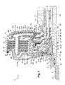
- a clutch device 1 according to one embodiment of the invention is illustrated in FIGS. Figures 1 to 3 . It comprises a torque input member 2 comprising a front portion 3 extending axially and intended to be coupled to a damping device, itself coupled to a crankshaft of an internal combustion engine of a motor vehicle, and a rear portion 4 extending radially.
- the front part 3 comprises, from front to rear, a first cylindrical portion and a second cylindrical portion 6 and larger in diameter than the first portion 5.
- the radial rear portion 4 has a cylindrical rim 7 extending forward and having a diameter larger than the diameter of the second cylindrical portion 6.
- the first part 5 serves for mounting a bearing.
- the second part 6 is intended to be coupled to the damping device, for example by means of complementary splines.
- the cylindrical rim 7 is intended to support a seal in order to prevent fluid, such as oil, escaping from the engine side of the vehicle.
- the radially outer periphery of the rear portion 4 of the torque input member 2 is rotatably coupled to a first external support 8. More particularly, the first external support 8 has a generally cylindrical front portion 9 and an annular rear portion. Extending radially inwardly from the front portion 9.
- the radially outer periphery of the torque input member 2 is rotatably coupled to the front portion 9 and is held axially in position by means of an elastic ring or circlip 11.
- the torque input member 2 and the first external support 8 delimit an internal volume 12.
- First discs 13 are further mounted on the front portion 9 of the first external support 8, the first discs 13 being spaced from each other, housed in the aforementioned internal volume 12 and slidable along said front portion 9.
- the inner periphery of the rear portion 10 of the first external support 8 is fixed, for example by welding, to a fluid supply hub 14, for example oil.
- a first seal support 15 is further secured, for example by spot welding or riveting, to the front face of the rear portion 10 of the first external support 8.
- the first seal support 15 has a cylindrical front portion 16 for at supporting a lip seal 17 and a rear radial annular portion 18 fixed to the first external support 8.
- the clutch device 1 further comprises a second external support 19 comprising, as previously, a cylindrical front portion 20 and an annular rear portion 21 extending radially and whose radially inner periphery is fixed, for example by welding, to the hub 14. More particularly, the rear portion 21 comprises a radially inner zone 21a and a radially outer zone 21b extending radially and axially offset from each other. The radially inner zone 21a is offset forwards with respect to the radially outer zone 21b and is connected thereto by a cylindrical shoulder 21c.
- the rear portion 21 of the second external support 19 is mounted in front of the rear portion 10 of the first external support 8, the second external support 19 being housed inside the internal volume 12.
- Second disks 22 are further mounted on the front portion 20 of the second outer support 19, the second disks 22 being spaced from each other and are slidable along said front portion 20.
- a second seal support 23 is further secured, for example by spot welding or riveting, to the front face of the zone 21a of the rear portion 21.
- the second seal support 23 has a front cylindrical portion 24 for supporting a lip seal 25 and a rear radial annular portion 26 fixed to the second external support 19.
- the clutch device 1 further comprises a first internal support 27 comprising a radially extending annular front portion 28 and a cylindrical rear portion 29 extending from the radially outer periphery of the front portion 28.
- a first cylindrical hub 30 is located at the radially inner periphery of the front portion 28.
- the first cylindrical hub 30 has internal splines cooperating with external splines of a first torque output shaft 31 or first input shaft of a gearbox. This tree 31 is for example associated with odd gear ratios of the gearbox.
- First counter-discs 32 are coupled in rotation to the rear portion 29 of the first internal support 27 and are interposed each time between two first discs 13, the first against-discs 32 being able to slide along said rear portion 29.
- Each counter-disk 32 carries friction linings 33, as is well known per se.
- the first discs 13 and the first counter-discs 32 form a first wet clutch mechanism.
- the device further comprises a second internal support 33 comprising an annular front portion 34 extending radially and a cylindrical rear portion 35 extending from the radially outer periphery of the front portion 34.
- a second cylindrical hub 36 is located peripherally radially.
- the second cylindrical hub 36 has internal splines cooperating with external splines of a second torque output shaft 37 or second input shaft of a gearbox. This shaft 37 is for example associated with gear ratios even transmission.
- the torque output shafts 31, 37 and the feed hub 14 are coaxial, the second torque output shaft 37 being mounted within the feed hub 14, the first torque output shaft 31 being mounted inside the second torque output shaft 37.
- Second counter-discs 38 are rotatably coupled to the rear portion 35 of the second internal support 33 and are interposed each time between two second discs 22, the second counter-discs 38 being able to slide along said rear part 35.
- Each counter-disk 38 carries friction linings 39.
- Second discs 22 and second counter-discs 39 form a second wet clutch mechanism.
- the second Clutch mechanism is located radially inside the first clutch mechanism.
- the front portion 28 of the first internal support 27 is located axially between the radial portion 4 of the torque input member 2 and the front portion 34 of the second internal support 33.
- the front portion 34 of the second internal support 33 is located axially. between the front portion 28 of the first inner support 27 and the front end of the feed hub 14.
- a bearing 40 is mounted axially between the torque input member 2 and the first internal support 27.
- a bearing 41 is mounted axially between the first internal support 27 and the second internal support 33.
- a bearing 42 is mounted axially between the second internal support 33 and the feed hub 14.
- a bearing 43 is mounted radially between the front end of the first torque output shaft 31 and the front portion 3 of the torque input member 2.
- Bearings 44 are further mounted radially between the hub 14 and the second shaft 37. These bearings 43, 44 are for example formed by roller bearings.
- the clutch device 1 also comprises a first piston 45, associated with the first clutch mechanism.
- the first piston 45 is mounted axially between the first external support 8 and the second external support 19.
- the first piston 45 generally comprises two radially extending zones 45a, 45b radially offset from one another, delimiting between them a cylindrical shoulder 45c.
- the radially inner periphery of the first piston 45 is equipped with a lip seal 46 resting on the outer surface of the supply hub 14.
- the seal 17 bears on the radially inner surface of the shoulder 45c of the first piston 45.
- a first sealed pressure chamber 47 is thus delimited by the zone 45b, the shoulder 45c, the seal support 15, the radially inner periphery of the first external support 8 and the feed hub 14.
- the radially outer periphery 45d of the first piston 45 is able to bear against one of the first discs 13.
- the first piston 45 is axially displaceable between a clutch position in which the first piston 45 tends to press the first discs 13 on the first counter-disks 32 associated with the first clutch mechanism, and a disengagement position in which the first piston 45 tends to release the first disks 13 and the first counter-disks 32 of the first clutch mechanism.
- a first washer 48 is mounted in front of the first piston 45, said first washer 48 being fixed on the rear face of the rear portion 21 of the second external support 19, more particularly in the zone 21a, said first washer 48 having an annular portion radial radial front 49, whose radially outer periphery is extended axially rearwardly by a cylindrical rear portion 50, located radially inside the shoulder 21c.
- a first elastic return member such as for example a Belleville washer 51, is mounted axially between the front portion 49 of the first washer 48 and the first piston 45.
- the first elastic return member 51 thus tends to recall the first piston 45 to its disengaged position.
- the first clutch mechanism is therefore of the normally open type.
- a first counterpressure chamber 52 is thus defined by the first washer 48, the first piston 45, the radially inner periphery of the second external support 19 and the feed hub 14.
- the clutch device comprises a second piston 53, associated with the second clutch mechanism.
- the second piston 53 is mounted axially between the second external support 19 and the second internal support 33.
- the second piston 53 carries a lip seal 54 at its inner periphery, said seal 54 resting on the supply hub 14, and a lip seal 55 at a shoulder 53c, said seal 55 bearing on a cylindrical portion of a second washer 56.
- the second washer 56 is mounted around the feed hub 14 and is placed in contact with it.
- a second elastic return member such as for example a Belleville washer 57, is mounted between the second washer 56 and the second piston 53.
- a second sealed pressure chamber 58 is delimited by the second piston 53, the second seal carrier 23, the inner periphery of the second external support 19 and the feed hub 14.
- a second back pressure chamber 59 is delimited by the second washer 56, the second piston 53 and the feed hub 14.
- the radially outer periphery 53d of the second piston 53 is able to bear against one of the second discs 22.
- the second piston 53 is axially displaceable between a clutch position in which the second piston 53 tends to press the second discs 22 on the associated second counter-disks 38 of the second clutch mechanism, and a disengagement position in which the second piston 53 tends to release the second disks 22 and the second against-disks 38 of the second clutch mechanism.
- the feed hub 14 has three ducts 61 defining two fluid circuits, namely a cooling circuit, a so-called low-pressure circuit and a so-called high-pressure circuit. Both low and high pressure circuits are powered by corresponding pumps. At least one of said pumps has a drive member 62 which is fixed to the hub 14, for example by welding, directly behind the first external support 8.
- the high-pressure circuit opens into the first and second pressure chambers 47, 58 through orifices referenced respectively 63 and 64, while the low-pressure circuit opens into the first and second back pressure chambers 52, 59 and the internal volume 9 housing in particular the first and second clutch mechanisms, by orifices respectively referenced 65, 66 and 67.
- fluid under high pressure can be brought either to the first pressure chamber 47 or to the second pressure chamber 58, so as to respectively move the first piston 45 or the second piston 53 and thereby actuate the first mechanism clutch or the second clutch mechanism.
- the torque entering through the torque input member 2 is transmitted to the second torque output shaft via the first external support 8, the supply hub 14. , the second external support 19, the second clutch mechanism 22, 38 and the second internal support 33.
- the two clutch mechanisms can be actuated simultaneously at the time of the change of the gear ratio or at the moment of the torque transition.
- said pressure chambers 47, 58 are not subjected to a fluid at high pressure, then the return members 51, 57 tend to return the pistons 45, 53 to their disengaging positions.
- the first shaft 30 comprises a grooved front zone 68 engaged in the hub 30 of the first internal support 27 and cooperating with the splines thereof so as to ensure a rotational coupling of the first shaft 31 and the first internal support 27.
- the first shaft 30 further includes a groove 69 opening radially outward and located near or in the grooved area 68.
- the hub 30 of the first internal support 27 also comprises a groove 70 opening radially inwards, located axially opposite the groove 69.
- An elastic ring or circlip 71 is mounted both in the groove 69 of the first shaft 31 and in the groove 70 of the first internal support 27, so as to ensure the axial positioning of the first internal support 27 on the first shaft 31.
- the rear end of the hub 30 has a chamfer 72 located at the radially inner periphery of said hub 30. Furthermore, as illustrated in FIG. figure 3 , the first shaft 31 has recesses 73 uniformly distributed over the entire circumference, for example four in number, said recesses opening axially towards the front and in the groove 69 of the first shaft 31, said recesses 73 opening further radially towards the 'outside.
- Such a clutch device 1 can be mounted in the following manner.
- the assembly formed in particular by the torque input member 2, the external supports 8, 19, the internal supports 27, 33, the clutch mechanisms 13, 32; 22, 38, the feed hub 14, the pistons 45, 53, the washers 48, 56 and the resilient return members 51, 57 may be pre-assembled.
- This assembly is then engaged on the gearbox, in particular on the first and second shafts 31, 37 of the gearbox. During this engagement, the grooved areas of the first and second shafts 31, 37 are engaged in the corrugated hubs 30, 36 of the first and second internal supports 27, 33.
- the elastic ring 71 is deformed or constrained in an unlocked position in which it is housed only in the groove 69 of the first shaft 31, by pressing the radially outer periphery of said elastic ring 71 on the chamfer 72 of the hub 30 of the first internal support 27.
- the axial sliding of the first shaft 31 by The ratio to the corresponding corrugated hub 30 can be continued until the grooves 69, 70 are located axially opposite one another.
- the ring elastic 71 deploys in the locked position, so as to extend both in the groove 69 of the first shaft 31 and in the groove 70 of the corrugated hub 30.
- the invention thus proposes a clutch device 1 of little complex structure, particularly easy to assemble while being able to be disassembled in certain particular cases. Note however that such disassembly occurs only exceptionally.
Abstract
Description
- La présente invention concerne un dispositif d'embrayage pour un véhicule automobile.
- La demande de brevet
DE 10 2011 006 027 divulgue un dispositif d'embrayage pour un véhicule automobile, comprenant des moyens d'entrée de couple destinés à être couplés à un vilebrequin, un premier arbre de sortie de couple, un second arbre de sortie de couple, un premier mécanisme d'embrayage apte à coupler ou découpler les moyens d'entrée de couple et le premier arbre de sortie de couple, et un second mécanisme d'embrayage apte à coupler ou découpler les moyens d'entrée de couple et le second arbre de sortie de couple. Les premier et second mécanismes d'embrayage comportent respectivement des premiers et des seconds disques montés respectivement sur un premier et un second supports externes appartenant aux moyens d'entrée de couple. Les premiers et seconds mécanismes d'embrayage comportent en outre respectivement des premiers et des seconds contre-disques montés respectivement sur un premier et un second supports internes couplés en rotation respectivement au premier et au second arbres de sortie de couple. Chaque support interne comporte un moyeu radialement interne monté autour de l'arbre de sortie de couple correspondant, ledit moyeu et ledit arbre de sortie de couple correspondant comportant des moyens de couplage en rotation complémentaires, tels par exemple que des cannelures complémentaires. - En outre, le moyeu du premier support interne est maintenu axialement en position à l'aide de deux anneaux élastiques de type circlips et d'une rondelle d'ajustement permettant de réduire le jeu de montage axial.
- Le nombre d'éléments nécessaires à un tel montage est donc relativement important.
- Par ailleurs, afin de réaliser le montage d'un tel dispositif d'embrayage sur une boîte de vitesses, c'est-à-dire afin de monter les moyeu des supports internes sur les arbres de sortie de couple correspondants (qui forment également les arbres d'entrée de la boîte de vitesses), il est nécessaire de démonter une partie du dispositif, en particulier les moyens d'entrée de couple, afin d'avoir accès aux anneaux élastiques.
- Ceci est relativement fastidieux, couteux et peut être source d'erreur ou d'endommagement du dispositif lors de son montage sur la boîte de vitesses.
- L'invention a notamment pour but d'apporter une solution simple, efficace et économique aux problèmes précités.
- A cet effet, elle propose un dispositif d'embrayage pour un véhicule automobile, comprenant des moyens d'entrée de couple destinés à être couplés à un vilebrequin, un premier arbre de sortie de couple, un second arbre de sortie de couple, un premier mécanisme d'embrayage apte à coupler ou découpler les moyens d'entrée de couple et le premier arbre de sortie de couple, un second mécanisme d'embrayage apte à coupler ou découpler les moyens d'entrée de couple et le second arbre de sortie de couple, les premier et second mécanismes d'embrayage comportant respectivement des premiers et des seconds disques montés respectivement sur un premier et un second supports externes appartenant aux moyens d'entrée de couple, les premiers et seconds mécanismes d'embrayage comportant en outre respectivement des premiers et des seconds contre-disques montés respectivement sur un premier et un second supports internes couplés en rotation respectivement au premier et au second arbres de sortie de couple, le premier support interne et/ou le second support interne comportant un moyeu radialement interne monté autour de l'arbre de sortie de couple correspondant, ledit moyeu et ledit arbre de sortie de couple correspondant comportant des moyens de couplage en rotation complémentaires, tels par exemple que des cannelures complémentaires, et des moyens de positionnement axiaux dudit moyeu sur l'arbre de sortie de couple correspondant, caractérisé en ce que les moyens de positionnement axiaux comportent au moins une gorge ménagée dans l'arbre de sortie de couple correspondant, au moins une gorge ménagée dans ledit moyeu, et au moins un anneau élastique apte à être déformé entre une position déverrouillée dans laquelle ledit anneau élastique est logé dans la gorge de l'arbre de sortie de couple correspondant de façon à permettre le montage du moyeu autour dudit arbre de sortie correspondant, et une position verrouillée dans laquelle ledit anneau élastique est logé à la fois dans la gorge dudit arbre de sortie correspondant et dans la gorge dudit moyeu, de manière à immobiliser axialement le support interne correspondant sur l'arbre de sortie correspondant.
- Le montage du moyeu sur l'arbre de sortie de couple correspondant ne nécessite ainsi plus qu'un seul anneau élastique, le jeu axial de montage étant déterminé par la tolérance dimensionnelle au niveau de la dimension axiale de l'anneau et des dimensions axiales des gorges correspondantes du moyeu et de l'arbre de sortie. Le coût et la complexité d'un tel dispositif d'embrayage sont donc réduits, par comparaison avec l'art antérieur.
- Selon une caractéristique de l'invention, le moyeu comporte un chanfrein ou un congé au niveau de l'une des extrémités axiales de sa périphérie radialement interne, l'anneau élastique étant apte à être déplacé vers sa position déverrouillée lors du montage du moyeu autour de l'arbre de sortie correspondant, par appui dudit anneau élastique sur le chanfrein ou le congé du moyeu.
- Ainsi, le montage du moyeu du support interne peut être réalisé aisément sur l'arbre de sortie de couple correspondant, l'anneau élastique venant se déformer puis s'engager ou se verrouiller dans les gorges précitées, sans intervention d'un opérateur et sans démontage d'une partie du dispositif, contrairement à l'art antérieur.
- Par ailleurs, le moyeu correspondant comporte au moins un évidement s'étendant axialement, débouchant axialement dans la gorge dudit moyeu.
- Un tel évidement permet de pouvoir contraindre et déverrouiller l'anneau élastique à l'aide d'un outil, de façon à pouvoir extraire le moyeu du support interne hors de l'arbre de sortie de couple. On notera cependant qu'un tel démontage n'intervient qu'exceptionnellement.
- De préférence, les deux arbres de sortie de couple sont coaxiaux, le premier arbre de sortie de couple étant monté radialement à l'intérieur du second arbre de sortie de couple, le premier mécanisme d'embrayage étant situé radialement à l'extérieur du second mécanisme d'embrayage.
- En outre, les premier et second mécanismes d'embrayage peuvent être des mécanismes d'embrayage humides, c'est-à-dire lubrifiés à l'aide d'un fluide, tel que de l'huile.
- Dans ce cas, les moyens d'entrée de couple peuvent comporter un organe d'entrée de couple, couplé en rotation au premier support externe et délimitant avec celui-ci un volume interne dans lequel sont logés les premiers et seconds mécanismes d'embrayage et dans lequel un fluide est destiné à lubrifier et refroidir notamment lesdits mécanismes d'embrayage, les moyens d'entrée de couple comportant en outre un moyeu d'alimentation en fluide couplé en rotation aux supports externes, ledit moyeu d'alimentation entourant le second arbre de sortie de couple, le premier support interne étant situé axialement entre l'organe d'entrée de couple et le second support interne, le second support interne étant situé axialement entre le premier support interne et le moyeu d'alimentation.
- Un premier palier peut alors être monté axialement entre l'organe d'entrée de couple et le premier support interne, un second palier étant monté axialement entre le premier support interne et le second support interne, un troisième palier étant monté axialement entre le second support interne et le moyeu d'alimentation, le moyeu d'alimentation étant fixe axialement par rapport au premier support externe, lui-même fixe axialement par rapport à l'organe d'entrée de couple.
- Ces paliers sont par exemple des butées à aiguilles.
- De plus, chaque mécanisme d'embrayage peut être associé à un piston apte à être actionné entre une position d'embrayage dans laquelle ledit piston plaque les disques sur les contre-disques associés du mécanisme d'embrayage correspondant, et une position de débrayage dans laquelle ledit piston libère les disques et les contre-disques du mécanisme d'embrayage correspondant.
- Dans ce cas, chaque piston peut être associé à une chambre de pression et une chambre de contre-pression, chaque piston étant en outre soumis à un effort de rappel appliqué par un organe de rappel élastique, tel par exemple qu'une rondelle élastique, tendant à rappeler le piston vers sa position débrayée.
- L'invention concerne également un véhicule automobile comportant au moins un dispositif du type précité.
- L'invention sera mieux comprise et d'autres détails, caractéristiques et avantages de l'invention apparaîtront à la lecture de la description suivante faite à titre d'exemple non limitatif en référence aux dessins annexés dans lesquels :
- la
figure 1 est une demi-vue en coupe d'un dispositif d'embrayage selon l'invention, - la
figure 2 est une vue de détail d'une partie de lafigure 1 , - la
figure 3 est une vue en perspective d'une partie du dispositif. - Un dispositif d'embrayage 1 selon une forme de réalisation de l'invention est illustré aux
figures 1 à 3 . Celui-ci comporte un organe d'entrée de couple 2 comprenant une partie avant 3 s'étendant axialement et destinée à être couplée à un dispositif d'amortissement, lui-même couplé à un vilebrequin d'un moteur à combustion interne d'un véhicule automobile, et une partie arrière 4 s'étendant radialement. La partie avant 3 comporte, d'avant en arrière, une première partie 5 cylindrique et une deuxième partie 6 cylindrique et de plus grand diamètre que la première partie 5. La partie arrière radiale 4 comporte un rebord cylindrique 7 s'étendant vers l'avant et présentant un diamètre plus grand que le diamètre de la deuxième partie cylindrique 6. - La première partie 5 sert au montage d'un roulement. La deuxième partie 6 est destinée à être couplée au dispositif d'amortissement, par exemple par l'intermédiaire de cannelures complémentaires. Le rebord cylindrique 7 est destiné à supporter un joint afin d'éviter que du fluide, tel que de l'huile, ne s'échappe du côté du moteur du véhicule.
- La périphérie radialement externe de la partie arrière 4 de l'organe d'entrée de couple 2 est couplée en rotation à un premier support externe 8. Plus particulièrement, le premier support externe 8 comporte une partie avant 9 globalement cylindrique et une partie arrière annulaire 10 s'étendant radialement vers l'intérieur depuis la partie avant 9.
- La périphérie radialement externe de l'organe d'entrée de couple 2 est couplée en rotation à la partie avant 9 et est maintenue axialement en position à l'aide d'un anneau élastique ou circlips 11. L'organe d'entrée de couple 2 et le premier support externe 8 délimitent un volume interne 12.
- Des premiers disques 13 sont en outre montés sur la partie avant 9 du premier support externe 8, les premiers disques 13 étant espacés les uns des autres, logés dans le volume interne 12 précité et aptes à coulisser le long de ladite partie avant 9.
- La périphérie interne de la partie arrière 10 du premier support externe 8 est fixée, par exemple par soudage, à un moyeu d'alimentation en fluide 14, par exemple en huile. Un premier support de joint 15 est en outre fixé, par exemple par soudage par point ou par rivetage, sur la face avant de la partie arrière 10 du premier support externe 8. Le premier support de joint 15 comporte une partie cylindrique avant 16, destinée à supporter un joint à lèvre 17, et une partie annulaire radiale arrière 18, fixée sur le premier support externe 8.
- Le dispositif d'embrayage 1 comporte en outre un second support externe 19 comportant, comme précédemment, une partie avant cylindrique 20 et une partie arrière annulaire 21 s'étendant radialement et dont la périphérie radialement interne est fixée, par exemple par soudage, au moyeu d'alimentation 14. Plus particulièrement la partie arrière 21 comporte une zone radialement interne 21a et une zone radialement externe 21 b s'étendant radialement et décalées axialement l'une de l'autre. La zone radialement interne 21a est décalée vers l'avant par rapport à la zone radialement externe 21 b et est reliée à cette dernière par un épaulement cylindrique 21 c.
- La partie arrière 21 du second support externe 19 est monté en avant de la partie arrière 10 du premier support externe 8, le second support externe 19 étant logé à l'intérieur du volume interne 12. Des seconds disques 22 sont en outre montés sur la partie avant 20 du second support externe 19, les seconds disques 22 étant espacés les uns des autres et sont aptes à coulisser le long de ladite partie avant 20.
- Un second support de joint 23 est en outre fixé, par exemple par soudage par point ou par rivetage, sur la face avant de la zone 21 a de la partie arrière 21. Le second support de joint 23 comporte une partie cylindrique avant 24, destinée à supporter un joint à lèvre 25, et une partie annulaire radiale arrière 26, fixée sur le second support externe 19.
- Le dispositif d'embrayage 1 comporte de plus un premier support interne 27 comprenant une partie avant 28 annulaire s'étendant radialement et une partie arrière cylindrique 29 s'étendant depuis la périphérie radialement externe de la partie avant 28. Un premier moyeu cylindrique 30 est situé en périphérie radialement interne de la partie avant 28. Le premier moyeu cylindrique 30 comporte des cannelures internes coopérant avec des cannelures externes d'un premier arbre de sortie de couple 31 ou premier arbre d'entrée d'une boîte de vitesses. Cet arbre 31 est par exemple associé aux rapports de vitesses impairs de la boîte de vitesses.
- Des premiers contre-disques 32 sont couplés en rotation à la partie arrière 29 du premier support interne 27 et sont intercalés à chaque fois entre deux premiers disques 13, les premiers contre-disques 32 étant aptes à coulisser le long de ladite partie arrière 29. Chaque contre-disque 32 porte des garnitures de friction 33, comme cela est bien connu en soi.
- Les premiers disques 13 et les premiers contre-disques 32 forment un premier mécanisme d'embrayage humide.
- Le dispositif comporte en outre un second support interne 33 comprenant une partie avant annulaire 34 s'étendant radialement et une partie arrière cylindrique 35 s'étendant depuis la périphérie radialement externe de la partie avant 34. Un second moyeu cylindrique 36 est situé en périphérie radialement interne de la partie avant 34. Le second moyeu cylindrique 36 comporte des cannelures internes coopérant avec des cannelures externes d'un second arbre de sortie de couple 37 ou second arbre d'entrée d'une boîte de vitesses. Cet arbre 37 est par exemple associé aux rapports de vitesses pairs de la boîte de vitesses.
- Les arbres de sortie de couple 31, 37 et le moyeu d'alimentation 14 sont coaxiaux, le second arbre de sortie de couple 37 étant monté à l'intérieur du moyeu d'alimentation 14, le premier arbre de sortie de couple 31 étant monté à l'intérieur du second arbre de sortie de couple 37.
- Des seconds contre-disques 38 sont couplés en rotation à la partie arrière 35 du second support interne 33 et sont intercalés à chaque fois entre deux seconds disques 22, les seconds contre-disques 38 étant aptes à coulisser le long de ladite partie arrière 35. Chaque contre-disque 38 porte des garnitures de friction 39.
- Les seconds disques 22 et les seconds contre-disques 39 forment un second mécanisme d'embrayage humide. Le second mécanisme d'embrayage est situé radialement à l'intérieur du premier mécanisme d'embrayage.
- La partie avant 28 du premier support interne 27 est située axialement entre la partie radiale 4 de l'organe d'entrée de couple 2 et la partie avant 34 du second support interne 33. La partie avant 34 du second support interne 33 est située axialement entre la partie avant 28 du premier support interne 27 et l'extrémité avant du moyeu d'alimentation 14.
- Un palier 40 est monté axialement entre l'organe d'entrée de couple 2 et le premier support interne 27. Un palier 41 est monté axialement entre le premier support interne 27 et le second support interne 33. Un palier 42 est monté axialement entre le second support interne 33 et le moyeu d'alimentation 14. Ces paliers 40, 41, 42 sont par exemple formés par des butées à aiguilles.
- En outre, un palier 43 est monté radialement entre l'extrémité avant du premier arbre de sortie de couple 31 et la partie avant 3 de l'organe d'entrée de couple 2. Des paliers 44 sont en outre montés radialement entre le moyeu d'alimentation 14 et le second arbre 37. Ces paliers 43, 44 sont par exemple formés par des roulements à rouleaux.
- Le dispositif d'embrayage 1 comporte également un premier piston 45, associé au premier mécanisme d'embrayage. Le premier piston 45 est monté axialement entre le premier support externe 8 et le second support externe 19. Le premier piston 45 comporte globalement deux zones 45a, 45b s'étendant radialement et décalée axialement l'une de l'autre, délimitant entre elles un épaulement cylindrique 45c. La périphérie radialement interne du premier piston 45 est équipée d'un joint à lèvre 46 en appui sur la surface externe du moyeu d'alimentation 14. Par ailleurs, le joint 17 est en appui sur la surface radialement interne de l'épaulement 45c du premier piston 45. Une première chambre de pression étanche 47 est ainsi délimitée par la zone 45b, l'épaulement 45c, le support de joint 15, la périphérie radialement interne du premier support externe 8 et le moyeu d'alimentation 14.
- La périphérie radialement externe 45d du premier piston 45 est apte à venir en appui contre l'un des premiers disques 13. Le premier piston 45 est déplaçable axialement entre une position d'embrayage dans laquelle le premier piston 45 tend à plaquer les premier disques 13 sur les premier contre-disques 32 associés du premier mécanisme d'embrayage, et une position de débrayage dans laquelle le premier piston 45 tend à libérer les premier disques 13 et les premier contre-disques 32 du premier mécanisme d'embrayage.
- Une première rondelle 48 est montée en avant du premier piston 45, ladite première rondelle 48 étant fixée sur la face arrière de la partie arrière 21 du second support externe 19, plus particulièrement dans la zone 21 a, ladite première rondelle 48 comportant une partie annulaire radiale avant 49, dont la périphérie radialement externe est prolongée axialement vers l'arrière par une partie arrière cylindrique 50, située radialement à l'intérieur de l'épaulement 21 c.
- Un premier organe de rappel élastique, tel par exemple qu'une rondelle Belleville 51, est monté axialement entre la partie avant 49 de la première rondelle 48 et le premier piston 45. Le premier organe de rappel élastique 51 tend ainsi à rappeler le premier piston 45 vers sa position de débrayage. Le premier mécanisme d'embrayage est donc du type normalement ouvert.
- Le joint à lèvre 46 porté par l'épaulement 45c du premier piston 45 vient en appui sur la partie cylindrique arrière 50 de la première rondelle 48. Une première chambre de contre-pression 52 est ainsi délimitée par la première rondelle 48, le premier piston 45, la périphérie radialement interne du second support externe 19 et le moyeu d'alimentation 14.
- Par ailleurs, le dispositif d'embrayage comporte un second piston 53, associé au second mécanisme d'embrayage. Le second piston 53 est monté axialement entre le second support externe 19 et le second support interne 33. Comme précédemment, le second piston 53 porte un joint à lèvre 54 à sa périphérie interne, ledit joint 54 venant en appui sur le moyeu d'alimentation 14, et un joint à lèvre 55 au niveau d'un épaulement 53c, ledit joint 55 venant en appui sur une partie cylindrique d'une seconde rondelle 56. La seconde rondelle 56 est montée autour du moyeu d'alimentation 14 et est placée au contact de celui-ci. Un second organe de rappel élastique, tel par exemple qu'une rondelle Belleville 57, est monté entre la seconde rondelle 56 et le second piston 53.
- Une seconde chambre de pression étanche 58 est délimitée par le second piston 53, le second porte-joint 23, la périphérie interne du second support externe 19 et le moyeu d'alimentation 14. Une seconde chambre de contre-pression 59 est délimitée par la seconde rondelle 56, le second piston 53 et le moyeu d'alimentation 14.
- La périphérie radialement externe 53d du second piston 53 est apte à venir en appui contre l'un des seconds disques 22. Le second piston 53 est déplaçable axialement entre une position d'embrayage dans laquelle le second piston 53 tend à plaquer les seconds disques 22 sur les seconds contre-disques associés 38 du second mécanisme d'embrayage, et une position de débrayage dans laquelle le second piston 53 tend à libérer les seconds disques 22 et les seconds contre-disques 38 du second mécanisme d'embrayage.
- Le moyeu d'alimentation 14 comporte trois canalisations 61 définissant deux circuits de fluide, à savoir un circuit de refroidissement, un circuit dit basse pression et un circuit dit haute pression. Les deux circuits de basse et de haute pression sont alimentés par des pompes correspondantes. L'une au moins desdits pompes à un organe d'entraînement 62 qui est fixé au moyeu 14, par exemple par soudage, directement en arrière du premier support externe 8.
- Le circuit haute-pression débouche dans les première et seconde chambres de pression 47, 58 par des orifices référencés respectivement 63 et 64, tandis que le circuit basse-pression débouche dans les première et seconde chambres de contre-pression 52, 59 et dans le volume interne 9 logeant notamment les premier et second mécanismes d'embrayage, par des orifices référencés respectivement 65, 66 et 67.
- En fonctionnement, du fluide sous haute-pression peut être amené soit vers la première chambre de pression 47, soit vers la seconde chambre de pression 58, de façon à déplacer respectivement le premier piston 45 ou le second piston 53 et actionner ainsi le premier mécanisme d'embrayage ou le second mécanisme d'embrayage.
- Lors de l'embrayage du premier mécanisme d'embrayage, le couple entrant par l'organe d'entrée de couple 2 est transmis au premier arbre de sortie de couple 31 par l'intermédiaire du premier support externe 8, du premier mécanisme d'embrayage 13, 32 et du premier support interne 27.
- Lors de l'embrayage du second mécanisme d'embrayage, le couple entrant par l'organe d'entrée de couple 2 est transmis au second arbre de sortie de couple par l'intermédiaire du premier support externe 8, du moyeu d'alimentation 14, du second support externe 19, du second mécanisme d'embrayage 22, 38 et du second support interne 33.
- On notera que les deux mécanismes d'embrayage peuvent être actionnés simultanément au moment du changement du rapport de vitesse ou au moment de la transition de couple. Lorsque lesdites chambres de pression 47, 58 ne sont pas soumises à un fluide à haute-pression, alors les organes de rappel 51, 57 tendent à rappeler les pistons 45, 53 vers leurs positions de débrayage.
- On s'intéressera dans ce qui suit au montage du moyeu 30 du premier support interne 27 sur le premier arbre 31.
- Comme cela est mieux visible à la
figure 2 , le premier arbre 30 comporte une zone avant cannelée 68 engagée dans le moyeu 30 du premier support interne 27 et coopérant avec les cannelures de celui-ci de manière à assurer un couplage en rotation du premier arbre 31 et du premier support interne 27. Le premier arbre 30 comporte de plus une gorge 69 débouchant radialement vers l'extérieur et située à proximité ou dans la zone cannelée 68. Le moyeu 30 du premier support interne 27 comporte également une gorge 70 débouchant radialement vers l'intérieur, située axialement en regard de la gorge 69. Un anneau élastique ou circlips 71 est monté à la fois dans la gorge 69 du premier arbre 31 et dans la gorge 70 du premier support interne 27, de manière à assurer le positionnement axial du premier support interne 27 sur le premier arbre 31. - L'extrémité arrière du moyeu 30 comporte un chanfrein 72 situé au niveau de la périphérie radialement interne dudit moyeu 30. Par ailleurs, comme illustré à la
figure 3 , le premier arbre 31 comporte des évidements 73 régulièrement répartis sur toute la circonférence, par exemple au nombre de quatre, lesdits évidements débouchant axialement vers l'avant et dans la gorge 69 du premier arbre 31, lesdits évidements 73 débouchant en outre radialement vers l'extérieur. - Un tel dispositif d'embrayage 1 peut être monté de la façon suivante.
- L'ensemble formé notamment par l'organe d'entrée de couple 2, les supports externes 8, 19, les supports internes 27, 33, les mécanismes d'embrayage 13, 32 ; 22, 38, le moyeu d'alimentation 14, les pistons 45, 53, les rondelles 48, 56 et les organes de rappel élastiques 51, 57 peut être pré-monté. Cet ensemble est ensuite engagé sur la boîte de vitesses, en particulier sur les premier et seconds arbres 31, 37 de la boîte de vitesses. Lors de cet engagement, les zones cannelées des premiers et seconds arbres 31, 37 viennent s'engager dans les moyeux cannelés 30, 36 des premier et second supports internes 27, 33. En outre, l'anneau élastique 71 est déformé ou contraint dans une position déverrouillée dans laquelle il est logé uniquement dans la gorge 69 du premier arbre 31, par appui de la périphérie radialement externe dudit anneau élastique 71 sur le chanfrein 72 du moyeu 30 du premier support interne 27. Le coulissement axial du premier arbre 31 par rapport au moyeu cannelé correspondant 30 peut être poursuivi jusqu'à ce que les gorges 69, 70 soient situées axialement en regard l'une de l'autre. Dans cette position, l'anneau élastique 71 se déploie en position verrouillée, de façon à s'étendre à la fois dans la gorge 69 du premier arbre 31 et dans la gorge 70 du moyeu cannelé 30.
- On notera qu'un tel montage ne nécessite pas de démontage, même partiel, de l'ensemble pré-monté précité.
- A l'inverse, lorsque l'on souhaite démonter ledit ensemble des premiers et seconds arbres de sortie de couple 31, 37, il est nécessaire de démonter par exemple l'organe d'entrée de couple 2 afin qu'un opérateur puisse avoir accès à l'extrémité avant du premier arbre 31. Pour cela, le retrait de l'anneau élastique 11 permet de séparer l'organe d'entrée de couple 2 di premier support externe 8. Un outil peut alors être engagé axialement dans les évidements 73 du moyeu 30, de façon à contraindre l'anneau élastique 71 vers sa position déverrouillée, dans laquelle il est logé uniquement dans la gorge 69 du premier arbre 31. Il est alors possible de retirer l'ensemble précité, par coulissement vers l'arrière le long des premiers et seconds arbres de sortie de couple 31, 37.
- L'invention propose ainsi un dispositif d'embrayage 1 de structure peu complexe, particulièrement facile à monter tout en pouvant être démonté dans certains cas particuliers. On notera cependant qu'un tel démontage n'intervient qu'exceptionnellement.
Claims (10)
- Dispositif d'embrayage (1) pour un véhicule automobile, comprenant des moyens d'entrée de couple (2) destinés à être couplés à un vilebrequin, un premier arbre de sortie de couple (31), un second arbre de sortie de couple (37), un premier mécanisme d'embrayage apte à coupler ou découpler les moyens d'entrée de couple (2) et le premier arbre de sortie de couple (31), un second mécanisme d'embrayage apte à coupler ou découpler les moyens d'entrée de couple (2) et le second arbre de sortie de couple (37), les premier et second mécanismes d'embrayage comportant respectivement des premiers et des seconds disques (13, 22) montés respectivement sur un premier et un second supports externes (8, 19) appartenant aux moyens d'entrée de couple, les premiers et seconds mécanismes d'embrayage comportant en outre respectivement des premiers et des seconds contre-disques (32, 38) montés respectivement sur un premier et un second supports internes (27, 33) couplés en rotation respectivement au premier et au second arbres de sortie de couple (31, 37), le premier support interne (27) et/ou le second support interne (33) comportant un moyeu radialement interne (30) monté autour de l'arbre de sortie de couple correspondant (31), ledit moyeu (30) et ledit arbre de sortie de couple correspondant (31) comportant des moyens de couplage en rotation complémentaires, tels par exemple que des cannelures complémentaires, et des moyens de positionnement axiaux dudit moyeu sur l'arbre de sortie de couple correspondant, caractérisé en ce que les moyens de positionnement axiaux comportent au moins une gorge (69) ménagée dans l'arbre de sortie de couple correspondant (31), au moins une gorge (70) ménagée dans ledit moyeu (30), et au moins un anneau élastique (71) apte à être déformé entre une position déverrouillée dans laquelle ledit anneau élastique est logé dans la gorge (69) de l'arbre de sortie de couple correspondant (31) de façon à permettre le montage du moyeu (30) autour dudit arbre de sortie correspondant (31), et une position verrouillée dans laquelle ledit anneau élastique (71) est logé à la fois dans la gorge (69) dudit arbre de sortie correspondant (31) et dans la gorge (70) dudit moyeu (30), de manière à immobiliser axialement le support interne correspondant (27) sur l'arbre de sortie correspondant (31).
- Dispositif (1) selon la revendication 1, caractérisé en ce que le moyeu (30) comporte un chanfrein (72) ou un congé au niveau de l'une des extrémités axiales de sa périphérie radialement interne, l'anneau élastique (71) étant apte à être déplacé vers sa position déverrouillée lors du montage du moyeu (30) autour de l'arbre de sortie correspondant (31), par appui dudit anneau élastique (71) sur le chanfrein (72) ou le congé du moyeu (30).
- Dispositif (1) selon la revendication 1 ou 2, caractérisé en ce que le moyeu (30) comporte au moins un évidement (73) s'étendant axialement, débouchant axialement dans la gorge (70) dudit moyeu (30).
- Dispositif (1) selon l'une des revendications 1 à 3, caractérisé en ce que les deux arbres de sortie de couple (31, 37) sont coaxiaux, le premier arbre de sortie de couple (31) étant monté radialement à l'intérieur du second arbre de sortie de couple (37), le premier mécanisme d'embrayage (13, 32) étant situé radialement à l'extérieur du second mécanisme d'embrayage (22, 38).
- Dispositif (1) selon l'une des revendications 1 à 4, caractérisé en ce que les premier et second mécanismes d'embrayage sont des mécanismes d'embrayage humides.
- Dispositif (1) selon les revendications 4 et 5, caractérisé en ce que les moyens d'entrée de couple comportent un organe d'entrée de couple (2), couplé en rotation au premier support externe (8) et délimitant avec celui-ci un volume interne (9) dans lequel sont logés les premiers et seconds mécanismes d'embrayage et dans lequel un fluide est destiné à lubrifier et refroidir notamment lesdits mécanismes d'embrayage, les moyens d'entrée de couple comportant en outre un moyeu d'alimentation en fluide (14) couplé en rotation aux supports externes (8, 19), ledit moyeu d'alimentation (14) entourant le second arbre de sortie de couple (37), le premier support interne (27) étant situé axialement entre l'organe d'entrée de couple (2) et le second support interne (33), le second support interne (33) étant situé axialement entre le premier support interne (27) et le moyeu d'alimentation (14).
- Dispositif (1) selon la revendication 6, caractérisé en ce qu'un premier palier (40) est monté axialement entre l'organe d'entrée de couple (2) et le premier support interne (27), un second palier (41) étant monté axialement entre le premier support interne (27) et le second support interne (33), un troisième palier (42) étant monté axialement entre le second support interne (33) et le moyeu d'alimentation (14), le moyeu d'alimentation (14) étant fixe axialement par rapport au premier support externe (8), lui-même fixe axialement par rapport à l'organe d'entrée de couple (2).
- Dispositif (1) selon l'une des revendications 1 à 7, caractérisé en ce que chaque mécanisme d'embrayage est associé à un piston (45, 53) apte à être actionné entre une position d'embrayage dans laquelle ledit piston (45, 53) plaque les disques (13, 22) sur les contre-disques associés (32, 38) du mécanisme d'embrayage correspondant, et une position de débrayage dans laquelle ledit piston (45, 53) libère les disques (13, 22) et les contre-disques (32, 38) du mécanisme d'embrayage correspondant.
- Dispositif (1) selon la revendication 8, caractérisé en ce que chaque piston (45, 53) est associé à une chambre de pression (47, 58) et une chambre de contre-pression (52, 59), chaque piston (45, 53) étant en outre soumis à un effort de rappel appliqué par un organe de rappel élastique, tel par exemple qu'une rondelle élastique (51, 57), tendant à rappeler le piston (45, 53) vers sa position débrayée.
- Véhicule automobile comportant au moins un dispositif (1) selon l'une des revendications 1 à 9.
Applications Claiming Priority (1)
| Application Number | Priority Date | Filing Date | Title |
|---|---|---|---|
| FR1457498A FR3024508B1 (fr) | 2014-08-01 | 2014-08-01 | Dispositif d'embrayage pour un vehicule automobile |
Publications (2)
| Publication Number | Publication Date |
|---|---|
| EP2990678A1 true EP2990678A1 (fr) | 2016-03-02 |
| EP2990678B1 EP2990678B1 (fr) | 2017-02-01 |
Family
ID=52016718
Family Applications (1)
| Application Number | Title | Priority Date | Filing Date |
|---|---|---|---|
| EP15175488.4A Revoked EP2990678B1 (fr) | 2014-08-01 | 2015-07-06 | Dispositif d'embrayage pour un véhicule automobile |
Country Status (4)
| Country | Link |
|---|---|
| EP (1) | EP2990678B1 (fr) |
| KR (1) | KR20160016659A (fr) |
| CN (1) | CN105317878B (fr) |
| FR (1) | FR3024508B1 (fr) |
Cited By (3)
| Publication number | Priority date | Publication date | Assignee | Title |
|---|---|---|---|---|
| EP3527412A1 (fr) * | 2018-02-20 | 2019-08-21 | Valeo Embrayages | Dispositif de transmission pour vehicule hybride |
| DE102018128799A1 (de) | 2018-11-16 | 2020-05-20 | Schaeffler Technologies AG & Co. KG | Welle-Nabe-Verbindung für ein Getriebe mit einer Doppelkupplungsvorrichtung |
| CN111601727A (zh) * | 2017-11-22 | 2020-08-28 | 法雷奥离合器公司 | 用于混合动力车辆的传动装置 |
Families Citing this family (8)
| Publication number | Priority date | Publication date | Assignee | Title |
|---|---|---|---|---|
| DE102016125074A1 (de) * | 2016-10-06 | 2018-04-12 | Schaeffler Technologies AG & Co. KG | Kupplungseinrichtung |
| FR3062695B1 (fr) * | 2017-02-07 | 2019-03-22 | Valeo Embrayages | Mecanisme a double embrayages demontable |
| KR101871917B1 (ko) * | 2017-11-20 | 2018-06-27 | 주식회사 카펙발레오 | 차량용 듀얼 클러치 장치 |
| KR101871916B1 (ko) * | 2017-11-20 | 2018-06-27 | 주식회사 카펙발레오 | 차량용 듀얼 클러치 장치 |
| FR3090768B1 (fr) * | 2018-12-20 | 2022-01-21 | Valeo Embrayages | Dispositif de transmission pour véhicule automobile |
| WO2020229528A1 (fr) | 2019-05-14 | 2020-11-19 | Transmisiones Y Equipos Mecanicos, S.A. De Cv | Boîte à 8 vitesses |
| US11649861B2 (en) * | 2019-05-17 | 2023-05-16 | Transmisiones Y Equipos Mecanicos, S.A. De Cv | Double clutch unit in a transmission |
| EP3969771B1 (fr) * | 2019-05-17 | 2024-02-14 | Transmisiones Y Equipos Mecánicos, S.A. de C.V. | Flux d'énergie dans un embrayage concentrique double |
Citations (3)
| Publication number | Priority date | Publication date | Assignee | Title |
|---|---|---|---|---|
| US2886355A (en) * | 1955-08-09 | 1959-05-12 | Waldes Kohinoor Inc | Coupled assemblies and coupling ring for use therein |
| DE102007027117A1 (de) * | 2007-06-13 | 2008-12-24 | Volkswagen Ag | Kupplung |
| DE102011006027A1 (de) | 2011-03-24 | 2012-09-27 | Zf Friedrichshafen Ag | Ölzuführnabe für eine nasslaufende Doppelkupplung |
Family Cites Families (8)
| Publication number | Priority date | Publication date | Assignee | Title |
|---|---|---|---|---|
| US1442223A (en) * | 1919-12-22 | 1923-01-16 | Cleveland Steel Tool Company | Rivet set |
| DE10004190B4 (de) * | 1999-09-30 | 2013-02-07 | Volkswagen Ag | Mehrfach-Kupplungseinrichtung |
| DE10115454A1 (de) | 2001-01-25 | 2002-08-08 | Zf Sachs Ag | Mehrfach-Kupplungseinrichtung, ggf. in Kombination mit einer Torsionsschwingungsdämpferanordnung oder/und einer Elektromaschine |
| FR2861147B1 (fr) * | 2003-10-21 | 2005-12-30 | Valeo Embrayages | Embrayage, notamment pour vehicule automobile, et procede de montage de cet embrayage. |
| FR2919573B1 (fr) | 2007-08-01 | 2010-03-12 | Valeo Embrayages | Agencement pour la fixation d'un dispositif modulaire d'embrayage sur un arbre mene |
| DE102008009361B4 (de) | 2008-02-14 | 2009-11-12 | Gkn Driveline Deutschland Gmbh | Verbindungsanordnung mit Sicherungsring |
| ITMO20080224A1 (it) | 2008-09-02 | 2010-03-03 | Rossi Motoriduttori S P A | Dispositivo di fissaggio assiale di un albero rispetto ad un organo cavo, particolarmente per il fissaggio assiale dell'albero di un solare rispetto ad un portasatelliti in un rotismo epicicloidale multistadio. |
| DE102009052791A1 (de) | 2009-11-11 | 2011-07-07 | Knorr-Bremse Systeme für Nutzfahrzeuge GmbH, 80809 | Vorrichtung zum Koppeln einer Antriebswelle eines Nebenaggregates eines Nutzfahrzeuges mit einem Rädertrieb und Verfahren zur Herstellung dieser Vorrichtung |
-
2014
- 2014-08-01 FR FR1457498A patent/FR3024508B1/fr active Active
-
2015
- 2015-07-06 EP EP15175488.4A patent/EP2990678B1/fr not_active Revoked
- 2015-07-30 KR KR1020150107959A patent/KR20160016659A/ko unknown
- 2015-07-31 CN CN201510463222.1A patent/CN105317878B/zh active Active
Patent Citations (3)
| Publication number | Priority date | Publication date | Assignee | Title |
|---|---|---|---|---|
| US2886355A (en) * | 1955-08-09 | 1959-05-12 | Waldes Kohinoor Inc | Coupled assemblies and coupling ring for use therein |
| DE102007027117A1 (de) * | 2007-06-13 | 2008-12-24 | Volkswagen Ag | Kupplung |
| DE102011006027A1 (de) | 2011-03-24 | 2012-09-27 | Zf Friedrichshafen Ag | Ölzuführnabe für eine nasslaufende Doppelkupplung |
Cited By (6)
| Publication number | Priority date | Publication date | Assignee | Title |
|---|---|---|---|---|
| CN111601727A (zh) * | 2017-11-22 | 2020-08-28 | 法雷奥离合器公司 | 用于混合动力车辆的传动装置 |
| CN111601727B (zh) * | 2017-11-22 | 2024-02-20 | 法雷奥离合器公司 | 用于混合动力车辆的传动装置 |
| EP3527412A1 (fr) * | 2018-02-20 | 2019-08-21 | Valeo Embrayages | Dispositif de transmission pour vehicule hybride |
| FR3078028A1 (fr) * | 2018-02-20 | 2019-08-23 | Valeo Embrayages | Dispositif de transmission pour vehicule hybride |
| CN110171285A (zh) * | 2018-02-20 | 2019-08-27 | 法雷奥离合器公司 | 用于混合动力车辆的传动装置 |
| DE102018128799A1 (de) | 2018-11-16 | 2020-05-20 | Schaeffler Technologies AG & Co. KG | Welle-Nabe-Verbindung für ein Getriebe mit einer Doppelkupplungsvorrichtung |
Also Published As
| Publication number | Publication date |
|---|---|
| FR3024508A1 (fr) | 2016-02-05 |
| EP2990678B1 (fr) | 2017-02-01 |
| CN105317878B (zh) | 2019-04-23 |
| FR3024508B1 (fr) | 2016-07-22 |
| KR20160016659A (ko) | 2016-02-15 |
| CN105317878A (zh) | 2016-02-10 |
Similar Documents
| Publication | Publication Date | Title |
|---|---|---|
| EP2990678B1 (fr) | Dispositif d'embrayage pour un véhicule automobile | |
| EP3219998B1 (fr) | Mecanisme d' embrayage et procede d' assemblage d' un tel mecanisme sur une chaîne de transmission | |
| EP3366938B1 (fr) | Dispositif de rappel elastique pour mecanisme d'embrayage humide et embrayage humide comprenant un tel dispositif de rappel elastique | |
| EP3252333B1 (fr) | Système d'encliquetage axial pour un mécanisme d'embrayage | |
| EP3580468B1 (fr) | Mécanisme a double embrayage démontable | |
| EP1681481B1 (fr) | Elément de transmission à palier de centrage et de reprise d'effort | |
| EP2990680B1 (fr) | Dispositif d embrayage pour un véhicule automobile | |
| FR3024509A1 (fr) | Dispositif d'embrayage pour un vehicule automobile | |
| WO2018096114A1 (fr) | Assemblage radial d'un mecanisme d'embrayage sur une transmission | |
| EP3830439B1 (fr) | Double embrayage humide avec butée de sécurité apte à limiter la course d'un piston du système de commande | |
| FR2881490A1 (fr) | Dispositif de montage d'un palier sur un element de transmission. | |
| EP2988014B1 (fr) | Dispositif d'embrayage pour un véhicule automobile | |
| WO2019166516A1 (fr) | Dispositif de transmission pour vehicule hybride | |
| WO2019166511A1 (fr) | Dispositif de transmission pour vehicule | |
| FR3092373A1 (fr) | Double embrayage humide et dispositif de rappel elastique pour un tel double embrayage humide | |
| EP3857090B1 (fr) | Mecanisme a double embrayage humide compact | |
| FR3051863B1 (fr) | Mecanisme d'embrayage compact comportant des paliers radiaux distincts des paliers axiaux | |
| FR3083278A1 (fr) | Porte-disque assemble et mecanisme d'embrayage humide comprenant ce porte-disque assemble | |
| FR3058488A1 (fr) | Mecanisme a double embrayage compact et systeme de transmission comprenant un tel mecanisme a double embrayage | |
| FR3115081A1 (fr) | « dispositif de rappel elastique pour systeme d’embrayage » | |
| FR3102815A1 (fr) | Mecanisme d’embrayage multidisques comprenant une etancheite amelioree |
Legal Events
| Date | Code | Title | Description |
|---|---|---|---|
| PUAI | Public reference made under article 153(3) epc to a published international application that has entered the european phase |
Free format text: ORIGINAL CODE: 0009012 |
|
| 17P | Request for examination filed |
Effective date: 20150706 |
|
| AK | Designated contracting states |
Kind code of ref document: A1 Designated state(s): AL AT BE BG CH CY CZ DE DK EE ES FI FR GB GR HR HU IE IS IT LI LT LU LV MC MK MT NL NO PL PT RO RS SE SI SK SM TR |
|
| AX | Request for extension of the european patent |
Extension state: BA ME |
|
| RIC1 | Information provided on ipc code assigned before grant |
Ipc: F16D 13/52 20060101ALI20160830BHEP Ipc: F16D 1/116 20060101ALI20160830BHEP Ipc: F16B 21/18 20060101ALI20160830BHEP Ipc: F16D 21/06 20060101ALN20160830BHEP Ipc: F16D 13/38 20060101AFI20160830BHEP Ipc: F16D 25/0638 20060101ALI20160830BHEP |
|
| GRAP | Despatch of communication of intention to grant a patent |
Free format text: ORIGINAL CODE: EPIDOSNIGR1 |
|
| INTG | Intention to grant announced |
Effective date: 20161014 |
|
| STAA | Information on the status of an ep patent application or granted ep patent |
Free format text: STATUS: GRANT OF PATENT IS INTENDED |
|
| GRAS | Grant fee paid |
Free format text: ORIGINAL CODE: EPIDOSNIGR3 |
|
| GRAA | (expected) grant |
Free format text: ORIGINAL CODE: 0009210 |
|
| STAA | Information on the status of an ep patent application or granted ep patent |
Free format text: STATUS: THE PATENT HAS BEEN GRANTED |
|
| AK | Designated contracting states |
Kind code of ref document: B1 Designated state(s): AL AT BE BG CH CY CZ DE DK EE ES FI FR GB GR HR HU IE IS IT LI LT LU LV MC MK MT NL NO PL PT RO RS SE SI SK SM TR |
|
| REG | Reference to a national code |
Ref country code: GB Ref legal event code: FG4D Free format text: NOT ENGLISH |
|
| REG | Reference to a national code |
Ref country code: CH Ref legal event code: EP Ref country code: AT Ref legal event code: REF Ref document number: 865860 Country of ref document: AT Kind code of ref document: T Effective date: 20170215 |
|
| REG | Reference to a national code |
Ref country code: IE Ref legal event code: FG4D Free format text: LANGUAGE OF EP DOCUMENT: FRENCH |
|
| REG | Reference to a national code |
Ref country code: DE Ref legal event code: R096 Ref document number: 602015001407 Country of ref document: DE |
|
| REG | Reference to a national code |
Ref country code: NL Ref legal event code: MP Effective date: 20170201 |
|
| REG | Reference to a national code |
Ref country code: LT Ref legal event code: MG4D |
|
| REG | Reference to a national code |
Ref country code: AT Ref legal event code: MK05 Ref document number: 865860 Country of ref document: AT Kind code of ref document: T Effective date: 20170201 |
|
| PG25 | Lapsed in a contracting state [announced via postgrant information from national office to epo] |
Ref country code: IS Free format text: LAPSE BECAUSE OF FAILURE TO SUBMIT A TRANSLATION OF THE DESCRIPTION OR TO PAY THE FEE WITHIN THE PRESCRIBED TIME-LIMIT Effective date: 20170601 Ref country code: HR Free format text: LAPSE BECAUSE OF FAILURE TO SUBMIT A TRANSLATION OF THE DESCRIPTION OR TO PAY THE FEE WITHIN THE PRESCRIBED TIME-LIMIT Effective date: 20170201 Ref country code: FI Free format text: LAPSE BECAUSE OF FAILURE TO SUBMIT A TRANSLATION OF THE DESCRIPTION OR TO PAY THE FEE WITHIN THE PRESCRIBED TIME-LIMIT Effective date: 20170201 Ref country code: NO Free format text: LAPSE BECAUSE OF FAILURE TO SUBMIT A TRANSLATION OF THE DESCRIPTION OR TO PAY THE FEE WITHIN THE PRESCRIBED TIME-LIMIT Effective date: 20170501 Ref country code: GR Free format text: LAPSE BECAUSE OF FAILURE TO SUBMIT A TRANSLATION OF THE DESCRIPTION OR TO PAY THE FEE WITHIN THE PRESCRIBED TIME-LIMIT Effective date: 20170502 Ref country code: LT Free format text: LAPSE BECAUSE OF FAILURE TO SUBMIT A TRANSLATION OF THE DESCRIPTION OR TO PAY THE FEE WITHIN THE PRESCRIBED TIME-LIMIT Effective date: 20170201 |
|
| REG | Reference to a national code |
Ref country code: FR Ref legal event code: PLFP Year of fee payment: 3 |
|
| PG25 | Lapsed in a contracting state [announced via postgrant information from national office to epo] |
Ref country code: RS Free format text: LAPSE BECAUSE OF FAILURE TO SUBMIT A TRANSLATION OF THE DESCRIPTION OR TO PAY THE FEE WITHIN THE PRESCRIBED TIME-LIMIT Effective date: 20170201 Ref country code: SE Free format text: LAPSE BECAUSE OF FAILURE TO SUBMIT A TRANSLATION OF THE DESCRIPTION OR TO PAY THE FEE WITHIN THE PRESCRIBED TIME-LIMIT Effective date: 20170201 Ref country code: PT Free format text: LAPSE BECAUSE OF FAILURE TO SUBMIT A TRANSLATION OF THE DESCRIPTION OR TO PAY THE FEE WITHIN THE PRESCRIBED TIME-LIMIT Effective date: 20170601 Ref country code: PL Free format text: LAPSE BECAUSE OF FAILURE TO SUBMIT A TRANSLATION OF THE DESCRIPTION OR TO PAY THE FEE WITHIN THE PRESCRIBED TIME-LIMIT Effective date: 20170201 Ref country code: ES Free format text: LAPSE BECAUSE OF FAILURE TO SUBMIT A TRANSLATION OF THE DESCRIPTION OR TO PAY THE FEE WITHIN THE PRESCRIBED TIME-LIMIT Effective date: 20170201 Ref country code: NL Free format text: LAPSE BECAUSE OF NON-PAYMENT OF DUE FEES Effective date: 20170201 Ref country code: LV Free format text: LAPSE BECAUSE OF FAILURE TO SUBMIT A TRANSLATION OF THE DESCRIPTION OR TO PAY THE FEE WITHIN THE PRESCRIBED TIME-LIMIT Effective date: 20170201 Ref country code: AT Free format text: LAPSE BECAUSE OF FAILURE TO SUBMIT A TRANSLATION OF THE DESCRIPTION OR TO PAY THE FEE WITHIN THE PRESCRIBED TIME-LIMIT Effective date: 20170201 Ref country code: BG Free format text: LAPSE BECAUSE OF FAILURE TO SUBMIT A TRANSLATION OF THE DESCRIPTION OR TO PAY THE FEE WITHIN THE PRESCRIBED TIME-LIMIT Effective date: 20170501 |
|
| REG | Reference to a national code |
Ref country code: DE Ref legal event code: R026 Ref document number: 602015001407 Country of ref document: DE |
|
| PG25 | Lapsed in a contracting state [announced via postgrant information from national office to epo] |
Ref country code: IT Free format text: LAPSE BECAUSE OF FAILURE TO SUBMIT A TRANSLATION OF THE DESCRIPTION OR TO PAY THE FEE WITHIN THE PRESCRIBED TIME-LIMIT Effective date: 20170201 Ref country code: SK Free format text: LAPSE BECAUSE OF FAILURE TO SUBMIT A TRANSLATION OF THE DESCRIPTION OR TO PAY THE FEE WITHIN THE PRESCRIBED TIME-LIMIT Effective date: 20170201 Ref country code: CZ Free format text: LAPSE BECAUSE OF FAILURE TO SUBMIT A TRANSLATION OF THE DESCRIPTION OR TO PAY THE FEE WITHIN THE PRESCRIBED TIME-LIMIT Effective date: 20170201 Ref country code: RO Free format text: LAPSE BECAUSE OF FAILURE TO SUBMIT A TRANSLATION OF THE DESCRIPTION OR TO PAY THE FEE WITHIN THE PRESCRIBED TIME-LIMIT Effective date: 20170201 Ref country code: EE Free format text: LAPSE BECAUSE OF FAILURE TO SUBMIT A TRANSLATION OF THE DESCRIPTION OR TO PAY THE FEE WITHIN THE PRESCRIBED TIME-LIMIT Effective date: 20170201 |
|
| PLBI | Opposition filed |
Free format text: ORIGINAL CODE: 0009260 |
|
| PG25 | Lapsed in a contracting state [announced via postgrant information from national office to epo] |
Ref country code: SM Free format text: LAPSE BECAUSE OF FAILURE TO SUBMIT A TRANSLATION OF THE DESCRIPTION OR TO PAY THE FEE WITHIN THE PRESCRIBED TIME-LIMIT Effective date: 20170201 Ref country code: DK Free format text: LAPSE BECAUSE OF FAILURE TO SUBMIT A TRANSLATION OF THE DESCRIPTION OR TO PAY THE FEE WITHIN THE PRESCRIBED TIME-LIMIT Effective date: 20170201 |
|
| 26 | Opposition filed |
Opponent name: BORGWARNER INC. Effective date: 20171030 |
|
| PG25 | Lapsed in a contracting state [announced via postgrant information from national office to epo] |
Ref country code: SI Free format text: LAPSE BECAUSE OF FAILURE TO SUBMIT A TRANSLATION OF THE DESCRIPTION OR TO PAY THE FEE WITHIN THE PRESCRIBED TIME-LIMIT Effective date: 20170201 |
|
| REG | Reference to a national code |
Ref country code: IE Ref legal event code: MM4A |
|
| PG25 | Lapsed in a contracting state [announced via postgrant information from national office to epo] |
Ref country code: IE Free format text: LAPSE BECAUSE OF NON-PAYMENT OF DUE FEES Effective date: 20170706 |
|
| REG | Reference to a national code |
Ref country code: BE Ref legal event code: MM Effective date: 20170731 |
|
| PLAX | Notice of opposition and request to file observation + time limit sent |
Free format text: ORIGINAL CODE: EPIDOSNOBS2 |
|
| PG25 | Lapsed in a contracting state [announced via postgrant information from national office to epo] |
Ref country code: LU Free format text: LAPSE BECAUSE OF NON-PAYMENT OF DUE FEES Effective date: 20170706 |
|
| REG | Reference to a national code |
Ref country code: FR Ref legal event code: PLFP Year of fee payment: 4 |
|
| PG25 | Lapsed in a contracting state [announced via postgrant information from national office to epo] |
Ref country code: BE Free format text: LAPSE BECAUSE OF NON-PAYMENT OF DUE FEES Effective date: 20170731 |
|
| PLBB | Reply of patent proprietor to notice(s) of opposition received |
Free format text: ORIGINAL CODE: EPIDOSNOBS3 |
|
| PG25 | Lapsed in a contracting state [announced via postgrant information from national office to epo] |
Ref country code: MT Free format text: LAPSE BECAUSE OF FAILURE TO SUBMIT A TRANSLATION OF THE DESCRIPTION OR TO PAY THE FEE WITHIN THE PRESCRIBED TIME-LIMIT Effective date: 20170201 |
|
| REG | Reference to a national code |
Ref country code: CH Ref legal event code: PL |
|
| PG25 | Lapsed in a contracting state [announced via postgrant information from national office to epo] |
Ref country code: CH Free format text: LAPSE BECAUSE OF NON-PAYMENT OF DUE FEES Effective date: 20180731 Ref country code: LI Free format text: LAPSE BECAUSE OF NON-PAYMENT OF DUE FEES Effective date: 20180731 |
|
| PG25 | Lapsed in a contracting state [announced via postgrant information from national office to epo] |
Ref country code: HU Free format text: LAPSE BECAUSE OF FAILURE TO SUBMIT A TRANSLATION OF THE DESCRIPTION OR TO PAY THE FEE WITHIN THE PRESCRIBED TIME-LIMIT; INVALID AB INITIO Effective date: 20150706 Ref country code: MC Free format text: LAPSE BECAUSE OF FAILURE TO SUBMIT A TRANSLATION OF THE DESCRIPTION OR TO PAY THE FEE WITHIN THE PRESCRIBED TIME-LIMIT Effective date: 20170201 |
|
| PG25 | Lapsed in a contracting state [announced via postgrant information from national office to epo] |
Ref country code: CY Free format text: LAPSE BECAUSE OF FAILURE TO SUBMIT A TRANSLATION OF THE DESCRIPTION OR TO PAY THE FEE WITHIN THE PRESCRIBED TIME-LIMIT Effective date: 20170201 |
|
| PG25 | Lapsed in a contracting state [announced via postgrant information from national office to epo] |
Ref country code: MK Free format text: LAPSE BECAUSE OF FAILURE TO SUBMIT A TRANSLATION OF THE DESCRIPTION OR TO PAY THE FEE WITHIN THE PRESCRIBED TIME-LIMIT Effective date: 20170201 |
|
| GBPC | Gb: european patent ceased through non-payment of renewal fee |
Effective date: 20190706 |
|
| PG25 | Lapsed in a contracting state [announced via postgrant information from national office to epo] |
Ref country code: TR Free format text: LAPSE BECAUSE OF FAILURE TO SUBMIT A TRANSLATION OF THE DESCRIPTION OR TO PAY THE FEE WITHIN THE PRESCRIBED TIME-LIMIT Effective date: 20170201 |
|
| PG25 | Lapsed in a contracting state [announced via postgrant information from national office to epo] |
Ref country code: GB Free format text: LAPSE BECAUSE OF NON-PAYMENT OF DUE FEES Effective date: 20190706 |
|
| APBM | Appeal reference recorded |
Free format text: ORIGINAL CODE: EPIDOSNREFNO |
|
| APBP | Date of receipt of notice of appeal recorded |
Free format text: ORIGINAL CODE: EPIDOSNNOA2O |
|
| APAH | Appeal reference modified |
Free format text: ORIGINAL CODE: EPIDOSCREFNO |
|
| PG25 | Lapsed in a contracting state [announced via postgrant information from national office to epo] |
Ref country code: AL Free format text: LAPSE BECAUSE OF FAILURE TO SUBMIT A TRANSLATION OF THE DESCRIPTION OR TO PAY THE FEE WITHIN THE PRESCRIBED TIME-LIMIT Effective date: 20170201 |
|
| APBQ | Date of receipt of statement of grounds of appeal recorded |
Free format text: ORIGINAL CODE: EPIDOSNNOA3O |
|
| P01 | Opt-out of the competence of the unified patent court (upc) registered |
Effective date: 20230528 |
|
| PGFP | Annual fee paid to national office [announced via postgrant information from national office to epo] |
Ref country code: FR Payment date: 20230727 Year of fee payment: 9 Ref country code: DE Payment date: 20230712 Year of fee payment: 9 |
|
| APBU | Appeal procedure closed |
Free format text: ORIGINAL CODE: EPIDOSNNOA9O |
|
| REG | Reference to a national code |
Ref country code: DE Ref legal event code: R103 Ref document number: 602015001407 Country of ref document: DE Ref country code: DE Ref legal event code: R064 Ref document number: 602015001407 Country of ref document: DE |
|
| RDAF | Communication despatched that patent is revoked |
Free format text: ORIGINAL CODE: EPIDOSNREV1 |
|
| STAA | Information on the status of an ep patent application or granted ep patent |
Free format text: STATUS: PATENT REVOKED |
|
| RDAG | Patent revoked |
Free format text: ORIGINAL CODE: 0009271 |
|
| REG | Reference to a national code |
Ref country code: CH Ref legal event code: PL |
|
| 27W | Patent revoked |
Effective date: 20231206 |