EP2990656B1 - Vakuumpumpe - Google Patents
Vakuumpumpe Download PDFInfo
- Publication number
- EP2990656B1 EP2990656B1 EP15180797.1A EP15180797A EP2990656B1 EP 2990656 B1 EP2990656 B1 EP 2990656B1 EP 15180797 A EP15180797 A EP 15180797A EP 2990656 B1 EP2990656 B1 EP 2990656B1
- Authority
- EP
- European Patent Office
- Prior art keywords
- rotor
- stator
- magnetic bearing
- pump
- magnetic
- Prior art date
- Legal status (The legal status is an assumption and is not a legal conclusion. Google has not performed a legal analysis and makes no representation as to the accuracy of the status listed.)
- Active
Links
- 230000000903 blocking effect Effects 0.000 claims description 5
- 238000000034 method Methods 0.000 description 6
- 239000007789 gas Substances 0.000 description 5
- 238000005086 pumping Methods 0.000 description 4
- 230000015572 biosynthetic process Effects 0.000 description 2
- 238000001311 chemical methods and process Methods 0.000 description 1
- 230000006835 compression Effects 0.000 description 1
- 238000007906 compression Methods 0.000 description 1
- 238000005461 lubrication Methods 0.000 description 1
- 239000000463 material Substances 0.000 description 1
- 239000002245 particle Substances 0.000 description 1
- 230000000149 penetrating effect Effects 0.000 description 1
- 230000002028 premature Effects 0.000 description 1
Images

Classifications
-
- F—MECHANICAL ENGINEERING; LIGHTING; HEATING; WEAPONS; BLASTING
- F04—POSITIVE - DISPLACEMENT MACHINES FOR LIQUIDS; PUMPS FOR LIQUIDS OR ELASTIC FLUIDS
- F04D—NON-POSITIVE-DISPLACEMENT PUMPS
- F04D27/00—Control, e.g. regulation, of pumps, pumping installations or pumping systems specially adapted for elastic fluids
- F04D27/02—Surge control
- F04D27/0292—Stop safety or alarm devices, e.g. stop-and-go control; Disposition of check-valves
-
- F—MECHANICAL ENGINEERING; LIGHTING; HEATING; WEAPONS; BLASTING
- F04—POSITIVE - DISPLACEMENT MACHINES FOR LIQUIDS; PUMPS FOR LIQUIDS OR ELASTIC FLUIDS
- F04D—NON-POSITIVE-DISPLACEMENT PUMPS
- F04D19/00—Axial-flow pumps
- F04D19/02—Multi-stage pumps
- F04D19/04—Multi-stage pumps specially adapted to the production of a high vacuum, e.g. molecular pumps
- F04D19/048—Multi-stage pumps specially adapted to the production of a high vacuum, e.g. molecular pumps comprising magnetic bearings
-
- F—MECHANICAL ENGINEERING; LIGHTING; HEATING; WEAPONS; BLASTING
- F04—POSITIVE - DISPLACEMENT MACHINES FOR LIQUIDS; PUMPS FOR LIQUIDS OR ELASTIC FLUIDS
- F04D—NON-POSITIVE-DISPLACEMENT PUMPS
- F04D23/00—Other rotary non-positive-displacement pumps
- F04D23/008—Regenerative pumps
-
- F—MECHANICAL ENGINEERING; LIGHTING; HEATING; WEAPONS; BLASTING
- F04—POSITIVE - DISPLACEMENT MACHINES FOR LIQUIDS; PUMPS FOR LIQUIDS OR ELASTIC FLUIDS
- F04D—NON-POSITIVE-DISPLACEMENT PUMPS
- F04D29/00—Details, component parts, or accessories
- F04D29/05—Shafts or bearings, or assemblies thereof, specially adapted for elastic fluid pumps
- F04D29/056—Bearings
- F04D29/058—Bearings magnetic; electromagnetic
-
- F—MECHANICAL ENGINEERING; LIGHTING; HEATING; WEAPONS; BLASTING
- F16—ENGINEERING ELEMENTS AND UNITS; GENERAL MEASURES FOR PRODUCING AND MAINTAINING EFFECTIVE FUNCTIONING OF MACHINES OR INSTALLATIONS; THERMAL INSULATION IN GENERAL
- F16C—SHAFTS; FLEXIBLE SHAFTS; ELEMENTS OR CRANKSHAFT MECHANISMS; ROTARY BODIES OTHER THAN GEARING ELEMENTS; BEARINGS
- F16C32/00—Bearings not otherwise provided for
- F16C32/04—Bearings not otherwise provided for using magnetic or electric supporting means
- F16C32/0406—Magnetic bearings
- F16C32/0408—Passive magnetic bearings
- F16C32/0423—Passive magnetic bearings with permanent magnets on both parts repelling each other
- F16C32/0425—Passive magnetic bearings with permanent magnets on both parts repelling each other for radial load mainly
-
- F—MECHANICAL ENGINEERING; LIGHTING; HEATING; WEAPONS; BLASTING
- F16—ENGINEERING ELEMENTS AND UNITS; GENERAL MEASURES FOR PRODUCING AND MAINTAINING EFFECTIVE FUNCTIONING OF MACHINES OR INSTALLATIONS; THERMAL INSULATION IN GENERAL
- F16C—SHAFTS; FLEXIBLE SHAFTS; ELEMENTS OR CRANKSHAFT MECHANISMS; ROTARY BODIES OTHER THAN GEARING ELEMENTS; BEARINGS
- F16C2360/00—Engines or pumps
- F16C2360/44—Centrifugal pumps
- F16C2360/45—Turbo-molecular pumps
-
- F—MECHANICAL ENGINEERING; LIGHTING; HEATING; WEAPONS; BLASTING
- F16—ENGINEERING ELEMENTS AND UNITS; GENERAL MEASURES FOR PRODUCING AND MAINTAINING EFFECTIVE FUNCTIONING OF MACHINES OR INSTALLATIONS; THERMAL INSULATION IN GENERAL
- F16C—SHAFTS; FLEXIBLE SHAFTS; ELEMENTS OR CRANKSHAFT MECHANISMS; ROTARY BODIES OTHER THAN GEARING ELEMENTS; BEARINGS
- F16C35/00—Rigid support of bearing units; Housings, e.g. caps, covers
Definitions
- the invention relates to a vacuum pump, in particular a turbo-molecular pump or a side channel pump, with a rotor comprising a rotor shaft, a stator and a magnetic bearing space provided in the area of the pump inlet, in which a magnetic bearing is arranged for rotatably supporting the rotor shaft.
- the magnetic bearing can in particular comprise a permanent magnetic bearing.
- Vacuum pumps are used in various technical processes in order to create the vacuum required for the respective process.
- the vacuum pumps can be provided with different bearings to support the rotor shaft in a rotatable manner.
- One possible form of mounting for turbo-molecular pumps, for example, is the so-called hybrid mounting, in which the rotor shaft is mounted on the side facing the fore-vacuum by an oil or grease-lubricated roller bearing, especially ball bearings, and on the high-vacuum side, i.e. in the area of the pump inlet, by a permanent magnetic bearing.
- a magnetic bearing has the advantage that it runs with little vibration and without contact and does not require any lubrication.
- a rotor-side bearing half and a stator-side bearing half each of which comprises a ring stack of several permanent magnetic rings stacked on top of one another in the axial direction.
- the magnetic rings lie radially opposite one another with the formation of an annular gap. Since this annular gap extends over a large distance in the axial direction compared to its radial gap width, this annular gap is also referred to below as an axial annular gap.
- a disadvantage of such magnetic bearings is that, due to the required gap, the magnetic rings more or less the normally harmful process gases are exposed. These gases can damage the material of the magnetic rings through chemical processes, which can lead to premature failure of the vacuum pump.
- the DE 43 27 506 A1 and the DE 60 2004 000 798 T2 each disclose vacuum pumps with a rotor comprising a rotor shaft, a stator, a magnetic bearing space in which a magnetic bearing is arranged for the rotatable support of the rotor shaft, and a dynamic seal or movement seal.
- the invention is based on the object of specifying a vacuum pump of the type mentioned at the outset, in which process gas is prevented from penetrating into the magnetic bearing space provided in the area of the pump inlet while maintaining a structure that is kept as simple and compact as possible.
- the object is achieved by a vacuum pump having the features of claim 1.
- the vacuum pump which can in particular be a turbo-molecular pump or a side channel pump, comprises a rotor with a rotor shaft, a stator and a magnetic bearing space provided in the area of the pump inlet or on the high vacuum side, in which a magnetic bearing is arranged to rotatably support the rotor shaft , which can in particular include a permanent magnetic bearing.
- the vacuum pump comprises means to shut off the magnetic bearing space using the rotor rotating relative to the stator.
- a locking step is provided for shutting off the magnetic bearing space, which includes a dynamic labyrinth seal or Siegbahn step provided between the rotor and the stator.
- Fig. 2 and 3 show, in schematic partial representations, different examples of a vacuum pump which is a turbo-molecular pump, but this type of pump is not essential for the implementation or application of the invention.
- the protection of the magnetic bearing according to the invention can also be used with other types of pumps.
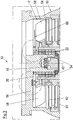
- the vacuum pump comprises a rotor 12 with a rotor shaft 14, a stator 16 and a magnetic bearing space 20 provided in the area of the pump inlet 18, in which a magnetic bearing 22 is arranged for the rotatable support of the rotor shaft 14.
- the magnetic bearing 22 can in particular comprise a permanent magnetic bearing.
- the magnetic bearing 22 has a rotor-side bearing half 24 and a stator-side bearing half 26, each of which comprises a ring stack of several permanent magnetic rings 28 and 30 stacked on top of one another in the axial direction.
- the magnet rings 28, 30 lie radially opposite one another with the formation of a narrow bearing gap 32, the rotor-side magnet rings 28 being disposed radially on the outside and the stator-side magnet rings 30 being disposed radially on the inside.
- the magnetic field present in the bearing gap 32 causes magnetic repulsive forces between the magnetic rings 28, 30, which cause the rotor shaft 14 to be supported radially.
- the ones in the Fig. 2 and 3 The vacuum pumps 10 shown each include means for evacuating or shutting off the magnetic storage space using the rotor 12 rotating relative to the stator 16 during operation.
- an axial annular gap 50 provided in the area of the magnetic bearing 20 between the rotor 12 and the stator 16 is designed as a pumping stage or blocking stage 52 acting on the magnetic bearing space 20.
- the axial annular gap 50 can, for example, have a structured, active pumping surface on the rotor and / or stator side, for example to form a Holweck or cross-thread pump stage.
- a structured pumping-active surface can in particular form one or more conveying channels which run helically or thread-like around the rotor axis 40 in the axial direction.
- the axial annular gap 50 can therefore be provided with a type of thread around the rotor axis 40 on the rotor and / or stator side.
- Such a pumping stage which can have a compression ratio of at least 2, for example, ensures that there is a lower pressure and thus a lower particle density of harmful molecules in the area of the magnetic rings 28, 30 than would be the case without this pumping stage. This leads to less attack on the magnetic rings 28, 30 by the process gases and thus to a longer service life of the magnetic bearing 22 in operation with aggressive pump media.
- the axial annular gap 50 can also be designed, for example, as a Gaede or Siegbahn step.
- an embodiment would also be conceivable, for example, according to which the axial annular gap 50 comprises a turbo-blade structure which is small in accordance with the spatial relationships.
- Fig. 3 shows an embodiment of a vacuum pump according to the invention, which has a locking step 54 for shutting off the magnetic bearing space 20, which includes a dynamic labyrinth seal or Siegbahn step provided between rotor 12 and stator 16.
- the relevant locking step 54 is arranged between the inlet-side rotor disk 58 and an inlet flange of the vacuum pump 10 assigned to the stator 16.
Description
- Die Erfindung betrifft eine Vakuumpumpe, insbesondere Turbomolekularpumpe oder Seitenkanalpumpe, mit einem eine Rotorwelle umfassenden Rotor, einem Stator und einem im Bereich des Pumpeneinlasses vorgesehenen Magnetlagerraum, in dem zur drehbaren Unterstützung der Rotorwelle ein Magnetlager angeordnet ist. Dabei kann das Magnetlager insbesondere ein Permanentmagnetlager umfassen.
- Vakuumpumpen werden in unterschiedlichen technischen Prozessen eingesetzt, um ein für den jeweiligen Prozess notwendiges Vakuum zu schaffen. Zur drehbaren Unterstützung der Rotorwelle können die Vakuumpumpen mit unterschiedlichen Lagerungen versehen sein. Eine mögliche Lagerungsform beispielsweise für Turbomolekularpumpen ist die sogenannte Hybridlagerung, bei der die Rotorwelle auf der dem Vorvakuum zugewandten Seite durch ein öl- oder fettgeschmiertes Wälzlager, insbesondere Kugellager, und auf der Hochvakuumseite, d.h. im Bereich des Pumpeneinlasses, durch ein Permanentmagnetlager gelagert ist. Ein Magnetlager besitzt den Vorteil, dass es vibrationsarm und berührungslos läuft und keinerlei Schmierung benötigt. Es umfasst in der Regel eine rotorseitige Lagerhälfte und eine statorseitige Lagerhälfte, die jeweils einen Ringstapel aus mehreren in axialer Richtung aufeinander gestapelten permanentmagnetischen Ringen umfassen. Die Magnetringe liegen einander unter Ausbildung eines Ringspalts radial gegenüber. Da sich dieser Ringspalt über eine im Vergleich zu seiner radialen Spaltbreite großen Strecke in axialer Richtung erstreckt, wird dieser Ringspalt nachstehend auch als axialer Ringspalt bezeichnet. Ein Nachteil solcher Magnetlager besteht allerdings darin, dass aufgrund des erforderlichen Spalts die Magnetringe mehr oder weniger den üblicherweise schädlichen Prozessgasen ausgesetzt sind. Diese Gase können das Material der Magnetringe durch chemische Prozesse schädigen, was zu einem vorzeitigen Ausfall der Vakuumpumpe führen kann.
- Die
DE 43 27 506 A1 und dieDE 60 2004 000 798 T2 offenbaren jeweils Vakuumpumpen mit einem eine Rotorwelle umfassenden Rotor, einem Stator, einem Magnetlagerraum, in dem zur drehbaren Unterstützung der Rotorwelle ein Magnetlager angeordnet ist, und einer dynamischen Dichtung bzw. Bewegungsdichtung. - Der Erfindung liegt die Aufgabe zugrunde, eine Vakuumpumpe der eingangs genannten Art anzugeben, bei der unter Aufrechterhaltung eines möglichst einfach und kompakt gehaltenen Aufbaus ein Eindringen von Prozessgas in den im Bereich des Pumpeneinlasses vorgesehenen Magnetlagerraum verhindert wird.
- Die Aufgabe wird erfindungsgemäß durch eine Vakuumpumpe mit den Merkmalen des Anspruchs 1 gelöst.
- Die Vakuumpumpe, bei der es sich insbesondere um eine Turbomolekularpumpe oder Seitenkanalpumpe handeln kann, umfasst einen Rotor mit einer Rotorwelle, einen Stator und einen im Bereich des Pumpeneinlasses bzw. auf der Hochvakuumseite vorgesehenen Magnetlagerraum, in dem zur drehbaren Unterstützung der Rotorwelle ein Magnetlager angeordnet ist, das insbesondere ein Permanentmagnetlager umfassen kann.
- Gemäß der Erfindung umfasst die Vakuumpumpe Mittel, um den Magnetlagerraum unter Nutzung des relativ zum Stator rotierenden Rotors abzusperren.
- Gemäß der Erfindung ist zum Absperren des Magnetlagerraums eine Sperrstufe vorgesehen, die eine zwischen Rotor und Stator vorgesehene dynamische Labyrinthdichtung oder Siegbahnstufe umfasst.
- Die Erfindung wird im Folgenden anhand der Zeichnung näher erläutert; in dieser zeigen:
- Fig. 2
- eine schematische Teildarstellung einer Vakuumpumpe, deren im Bereich des Pumpeneinlasses vorgesehener Magnetlagerraum unter Nutzung des relativ zum Stator rotierenden Rotors evakuiert bzw. abgesperrt wird, die aber nicht erfindungsgemäß ausgebildet ist, und
- Fig. 3
- eine schematische Darstellung einer beispielhaften Ausführungsform einer erfindungsgemäßen Vakuumpumpe, deren im Bereich des Pumpeneinlasses vorgesehener Magnetlagerraum unter Nutzung des relativ zum Stator rotierenden Rotors abgesperrt wird.
- Die
Fig. 2 und3 zeigen in schematischen Teildarstellungen unterschiedliche Beispiele einer Vakuumpumpe, bei der es sich um eine Turbomolekularpumpe handelt, wobei dieser Pumpentyp für die Realisierung bzw. Anwendung der Erfindung aber nicht zwingend ist. Der erfindungsgemäße Schutz der Magnetlagerung kann auch bei anderen Pumpentypen zum Einsatz kommen. - Die Vakuumpumpe umfasst einen Rotor 12 mit einer Rotorwelle 14, einen Stator 16 sowie einen im Bereich des Pumpeneinlasses 18 vorgesehenen Magnetlagerraum 20, in dem zur drehbaren Unterstützung der Rotorwelle 14 ein Magnetlager 22 angeordnet ist. Das Magnetlager 22 kann insbesondere ein Permanentmagnetlager umfassen.
- Das Magnetlager 22 weist eine rotorseitige Lagerhälfte 24 und eine statorseitige Lagerhälfte 26 auf, die jeweils einen Ringstapel aus mehreren in axialer Richtung aufeinandergestapelten permanentmagnetischen Ringen 28 bzw. 30 umfassen.
- Die Magnetringe 28, 30 liegen einander unter Ausbildung eines engen Lagerspalts 32 radial gegenüber, wobei die rotorseitigen Magnetringe 28 radial außen und die statorseitigen Magnetringe 30 radial innen angeordnet sind. Das in dem Lagerspalt 32 vorhandene magnetische Feld bewirkt magnetische Abstoßungskräfte zwischen den Magnetringen 28, 30, die eine radiale Lagerung der Rotorwelle 14 bewirken.
- Die in den
Fig. 2 und3 dargestellten Vakuumpumpen 10 umfassen jeweils Mittel, um den Magnetlagerraum unter Nutzung des während des Betriebs relativ zum Stator 16 rotierenden Rotors 12 zu evakuieren bzw. abzusperren. - Dabei ist bei der Ausführungsform gemäß
Fig. 2 ein im Bereich des Magnetlagers 20 vorgesehener axialer Ringspalt 50 zwischen dem Rotor 12 und dem Stator 16 als den Magnetlagerraum 20 beaufschlagende Pumpstufe bzw. Sperrstufe 52 ausgeführt. Hierzu kann der axiale Ringspalt 50 beispielsweise zur Bildung einer Holweck- oder Kreuzgewindepumpstufe rotor- und/oder statorseitig insbesondere eine strukturierte pumpaktive Fläche aufweisen. Eine solche strukturierte pumpaktive Fläche kann insbesondere einen oder mehrere Förderkanäle bilden, die schraubenlinienförmig bzw. gewindeartig um die Rotorachse 40 herum in axialer Richtung verlaufen. - Der axiale Ringspalt 50 kann also rotor- und/oder statorseitig mit einer Art Gewinde um die Rotorachse 40 versehen sein.
- Eine solche Pumpstufe, die z.B. ein Kompressionsverhältnis von mindestens 2 aufweisen kann, sorgt dafür, dass im Bereich der Magnetringe 28, 30 ein geringerer Druck und damit eine geringere Partikeldichte an Schadmolekülen vorhanden ist, als dies ohne diese Pumpstufe der Fall wäre. Dies führt zu einem geringeren Angriff der Magnetringe 28, 30 durch die Prozessgase und damit zu einer längeren Haltbarkeit des Magnetlagers 22 im Betrieb mit aggressiven Pumpmedien.
- Alternativ kann der axiale Ringspalt 50 beispielsweise auch als Gaede- oder Siegbahnstufe ausgeführt sein. Zudem wäre beispielsweise auch eine Ausführung denkbar, gemäß der der axiale Ringspalt 50 eine entsprechend den räumlichen Verhältnissen kleine Turboschaufelstruktur umfasst.
-
Fig. 3 zeigt eine Ausführungsform einer erfindungsgemäßen Vakuumpumpe, die zum Absperren des Magnetlagerraumes 20 eine Sperrstufe 54 aufweist, die eine zwischen Rotor 12 und Stator 16 vorgesehene dynamische Labyrinthdichtung oder Siegbahnstufe umfasst. - Beim vorliegenden Ausführungsbeispiel ist die betreffende Sperrstufe 54 zwischen der einlassseitigen Rotorscheibe 58 und einem dem Stator 16 zugeordneten Einlassflansch der Vakuumpumpe 10 angeordnet.
- In der Darstellung gemäß
Fig. 3 sind zudem auch wieder das Magnetlager 22, das Not- bzw. Fanglager 46 sowie Statorscheiben 62 und weitere Rotorscheiben 64 zu erkennen. -
- 10
- Vakuumpumpe
- 12
- Rotor
- 14
- Rotorwelle
- 16
- Stator
- 18
- Pumpeneinlass
- 20
- Magnetlagerraum
- 22
- Magnetlager
- 24
- rotorseitige Lagerhälfte
- 26
- statorseitige Lagerhälfte
- 28
- rotorseitiger Magnetring
- 30
- statorseitiger Magnetring
- 32
- Lagerspalt
- 40
- Rotorachse
- 46
- Not- bzw. Fanglagereinsatz
- 50
- Ringspalt
- 52
- Pumpstufe, Sperrstufe
- 54
- Sperrstufe
- 56
- Einlassflansch
- 58
- Rotorscheibe
- 62
- Statorscheibe
- 64
- Rotorscheibe
- 66
- Prozessgas
Claims (1)
- Vakuumpumpe (10), insbesondere Turbomolekularpumpe oder Seitenkanalpumpe, mit einem eine Rotorwelle (14) umfassenden Rotor (12), einem Stator (16) und einem im Bereich des Pumpeneinlasses (18) vorgesehenen Magnetlagerraum (20), in dem zur drehbaren Unterstützung der Rotorwelle (14) ein Magnetlager (22) angeordnet ist,
wobei Mittel (52, 54) vorgesehen sind, um den Magnetlagerraum (20) unter Nutzung des relativ zum Stator (16) rotierenden Rotors (12) abzusperren,
dadurch gekennzeichnet, dass zum Absperren des Magnetlagerraumes (20) eine Sperrstufe (54) vorgesehen ist, die eine zwischen Rotor (12) und Stator (16) vorgesehene dynamische Labyrinthdichtung oder Siegbahnstufe umfasst.
Applications Claiming Priority (1)
| Application Number | Priority Date | Filing Date | Title |
|---|---|---|---|
| DE102014112553.3A DE102014112553A1 (de) | 2014-09-01 | 2014-09-01 | Vakuumpumpe |
Publications (3)
| Publication Number | Publication Date |
|---|---|
| EP2990656A2 EP2990656A2 (de) | 2016-03-02 |
| EP2990656A3 EP2990656A3 (de) | 2016-07-13 |
| EP2990656B1 true EP2990656B1 (de) | 2021-07-28 |
Family
ID=53835954
Family Applications (1)
| Application Number | Title | Priority Date | Filing Date |
|---|---|---|---|
| EP15180797.1A Active EP2990656B1 (de) | 2014-09-01 | 2015-08-12 | Vakuumpumpe |
Country Status (3)
| Country | Link |
|---|---|
| EP (1) | EP2990656B1 (de) |
| JP (1) | JP6193320B2 (de) |
| DE (1) | DE102014112553A1 (de) |
Families Citing this family (2)
| Publication number | Priority date | Publication date | Assignee | Title |
|---|---|---|---|---|
| GB2578899B (en) * | 2018-11-13 | 2021-05-26 | Edwards Ltd | Vacuum pump |
| EP3628883B1 (de) * | 2019-12-09 | 2022-02-09 | Pfeiffer Vacuum Gmbh | Vakuumpumpe |
Citations (1)
| Publication number | Priority date | Publication date | Assignee | Title |
|---|---|---|---|---|
| JPS639495U (de) * | 1986-07-04 | 1988-01-22 |
Family Cites Families (9)
| Publication number | Priority date | Publication date | Assignee | Title |
|---|---|---|---|---|
| DE3818556A1 (de) * | 1988-06-01 | 1989-12-07 | Pfeiffer Vakuumtechnik | Magnetlager fuer eine schnell rotierende vakuumpumpe |
| JP2998441B2 (ja) * | 1992-08-19 | 2000-01-11 | 株式会社日立製作所 | ターボ真空ポンプ |
| JP3201348B2 (ja) * | 1998-05-25 | 2001-08-20 | 株式会社島津製作所 | ターボ分子ポンプ |
| JP2000161284A (ja) * | 1998-11-26 | 2000-06-13 | Hitachi Ltd | ターボ真空ポンプ |
| JP2001003890A (ja) * | 1999-06-23 | 2001-01-09 | Shimadzu Corp | 磁気軸受式ターボ分子ポンプ |
| JP2005042709A (ja) * | 2003-07-10 | 2005-02-17 | Ebara Corp | 真空ポンプ |
| FR2859250B1 (fr) * | 2003-08-29 | 2005-11-11 | Cit Alcatel | Pompe a vide |
| DE202012000611U1 (de) * | 2012-01-21 | 2013-04-23 | Oerlikon Leybold Vacuum Gmbh | Turbomolekularpumpe |
| DE102013100853A1 (de) * | 2013-01-29 | 2014-07-31 | Pfeiffer Vacuum Gmbh | Verfahren zum Beschichten und/oder Lackieren von Magnetringen eines Rotor-Magnetlagers, Rotor-Magnetlager sowie Vakuumpumpe |
-
2014
- 2014-09-01 DE DE102014112553.3A patent/DE102014112553A1/de active Pending
-
2015
- 2015-08-12 EP EP15180797.1A patent/EP2990656B1/de active Active
- 2015-08-31 JP JP2015170141A patent/JP6193320B2/ja active Active
Patent Citations (1)
| Publication number | Priority date | Publication date | Assignee | Title |
|---|---|---|---|---|
| JPS639495U (de) * | 1986-07-04 | 1988-01-22 |
Also Published As
| Publication number | Publication date |
|---|---|
| JP6193320B2 (ja) | 2017-09-06 |
| JP2016050582A (ja) | 2016-04-11 |
| DE102014112553A1 (de) | 2016-03-03 |
| EP2990656A2 (de) | 2016-03-02 |
| EP2990656A3 (de) | 2016-07-13 |
Similar Documents
| Publication | Publication Date | Title |
|---|---|---|
| EP2826999B1 (de) | Vakuumpumpe | |
| EP0159464B1 (de) | Molekularvakuumpumpe | |
| EP3657021B1 (de) | Vakuumpumpe | |
| EP1252446A1 (de) | Dynamische dichtung | |
| EP2990656B1 (de) | Vakuumpumpe | |
| DE3722164C2 (de) | Turbomolekularpumpe | |
| EP1706645A1 (de) | Mehrstufige reibungsvakuumpumpe | |
| EP3112687B1 (de) | Feststellung der strömung eines hilfsgases, das in eine vakuumpumpe gespeist wird | |
| DE60319585T2 (de) | Vakuumpumpe | |
| WO2010015501A1 (de) | Verwendung eines wälzlagers zur lagerung rotierender bauteile in vakuumeinrichtungen sowie vakuumeinrichtung | |
| EP3851680B1 (de) | Molekularvakuumpumpe und verfahren zum beeinflussen des saugvermögens einer solchen | |
| DE102015113821B4 (de) | Vakuumpumpe | |
| EP3196471B1 (de) | Vakuumpumpe | |
| EP3628873B1 (de) | Rotorlagerung | |
| EP3438460A1 (de) | Vakuumpumpe | |
| EP3088746B1 (de) | Vakuumpumpe | |
| EP3650702B1 (de) | Verwendung eines synthetischen öls in einer vakuumpumpe und vakuumpumpe | |
| EP3318763B1 (de) | Vakuumdichtung, doppeldichtung, vakuumsystem und vakuumpumpe | |
| DE102018119747B3 (de) | Turbomolekularpumpe für massenspektrometer | |
| EP3135932B1 (de) | Vakuumpumpe und permanentmagnetlager | |
| EP3327293B1 (de) | Vakuumpumpe mit mehreren einlässen | |
| EP2910791A1 (de) | Vakuumpumpe | |
| EP3267040B1 (de) | Turbomolekularpumpe | |
| EP3767109B1 (de) | Vakuumsystem | |
| DE102020116770A1 (de) | Vakuumpumpe mit integriertem miniaturventil |
Legal Events
| Date | Code | Title | Description |
|---|---|---|---|
| PUAI | Public reference made under article 153(3) epc to a published international application that has entered the european phase |
Free format text: ORIGINAL CODE: 0009012 |
|
| AK | Designated contracting states |
Kind code of ref document: A2 Designated state(s): AL AT BE BG CH CY CZ DE DK EE ES FI FR GB GR HR HU IE IS IT LI LT LU LV MC MK MT NL NO PL PT RO RS SE SI SK SM TR |
|
| AX | Request for extension of the european patent |
Extension state: BA ME |
|
| PUAL | Search report despatched |
Free format text: ORIGINAL CODE: 0009013 |
|
| AK | Designated contracting states |
Kind code of ref document: A3 Designated state(s): AL AT BE BG CH CY CZ DE DK EE ES FI FR GB GR HR HU IE IS IT LI LT LU LV MC MK MT NL NO PL PT RO RS SE SI SK SM TR |
|
| AX | Request for extension of the european patent |
Extension state: BA ME |
|
| RIC1 | Information provided on ipc code assigned before grant |
Ipc: F04D 23/00 20060101ALI20160603BHEP Ipc: F04D 27/02 20060101ALI20160603BHEP Ipc: F04D 19/04 20060101AFI20160603BHEP Ipc: F04D 29/058 20060101ALI20160603BHEP |
|
| STAA | Information on the status of an ep patent application or granted ep patent |
Free format text: STATUS: REQUEST FOR EXAMINATION WAS MADE |
|
| 17P | Request for examination filed |
Effective date: 20170113 |
|
| RBV | Designated contracting states (corrected) |
Designated state(s): AL AT BE BG CH CY CZ DE DK EE ES FI FR GB GR HR HU IE IS IT LI LT LU LV MC MK MT NL NO PL PT RO RS SE SI SK SM TR |
|
| STAA | Information on the status of an ep patent application or granted ep patent |
Free format text: STATUS: EXAMINATION IS IN PROGRESS |
|
| 17Q | First examination report despatched |
Effective date: 20190823 |
|
| STAA | Information on the status of an ep patent application or granted ep patent |
Free format text: STATUS: EXAMINATION IS IN PROGRESS |
|
| REG | Reference to a national code |
Ref country code: DE Ref legal event code: R079 Ref document number: 502015014983 Country of ref document: DE Free format text: PREVIOUS MAIN CLASS: F04D0019040000 Ipc: F16C0032040000 |
|
| GRAP | Despatch of communication of intention to grant a patent |
Free format text: ORIGINAL CODE: EPIDOSNIGR1 |
|
| STAA | Information on the status of an ep patent application or granted ep patent |
Free format text: STATUS: GRANT OF PATENT IS INTENDED |
|
| RIC1 | Information provided on ipc code assigned before grant |
Ipc: F04D 29/058 20060101ALI20210204BHEP Ipc: F04D 23/00 20060101ALI20210204BHEP Ipc: F04D 27/02 20060101ALI20210204BHEP Ipc: F16C 32/04 20060101AFI20210204BHEP Ipc: F04D 19/04 20060101ALI20210204BHEP |
|
| RAP1 | Party data changed (applicant data changed or rights of an application transferred) |
Owner name: PFEIFFER VACUUM GMBH |
|
| INTG | Intention to grant announced |
Effective date: 20210224 |
|
| GRAS | Grant fee paid |
Free format text: ORIGINAL CODE: EPIDOSNIGR3 |
|
| GRAA | (expected) grant |
Free format text: ORIGINAL CODE: 0009210 |
|
| STAA | Information on the status of an ep patent application or granted ep patent |
Free format text: STATUS: THE PATENT HAS BEEN GRANTED |
|
| AK | Designated contracting states |
Kind code of ref document: B1 Designated state(s): AL AT BE BG CH CY CZ DE DK EE ES FI FR GB GR HR HU IE IS IT LI LT LU LV MC MK MT NL NO PL PT RO RS SE SI SK SM TR |
|
| REG | Reference to a national code |
Ref country code: GB Ref legal event code: FG4D Free format text: NOT ENGLISH |
|
| REG | Reference to a national code |
Ref country code: CH Ref legal event code: EP |
|
| REG | Reference to a national code |
Ref country code: DE Ref legal event code: R096 Ref document number: 502015014983 Country of ref document: DE |
|
| REG | Reference to a national code |
Ref country code: AT Ref legal event code: REF Ref document number: 1414988 Country of ref document: AT Kind code of ref document: T Effective date: 20210815 |
|
| REG | Reference to a national code |
Ref country code: IE Ref legal event code: FG4D Free format text: LANGUAGE OF EP DOCUMENT: GERMAN |
|
| REG | Reference to a national code |
Ref country code: LT Ref legal event code: MG9D |
|
| REG | Reference to a national code |
Ref country code: NL Ref legal event code: MP Effective date: 20210728 |
|
| PG25 | Lapsed in a contracting state [announced via postgrant information from national office to epo] |
Ref country code: NL Free format text: LAPSE BECAUSE OF FAILURE TO SUBMIT A TRANSLATION OF THE DESCRIPTION OR TO PAY THE FEE WITHIN THE PRESCRIBED TIME-LIMIT Effective date: 20210728 Ref country code: PT Free format text: LAPSE BECAUSE OF FAILURE TO SUBMIT A TRANSLATION OF THE DESCRIPTION OR TO PAY THE FEE WITHIN THE PRESCRIBED TIME-LIMIT Effective date: 20211129 Ref country code: NO Free format text: LAPSE BECAUSE OF FAILURE TO SUBMIT A TRANSLATION OF THE DESCRIPTION OR TO PAY THE FEE WITHIN THE PRESCRIBED TIME-LIMIT Effective date: 20211028 Ref country code: ES Free format text: LAPSE BECAUSE OF FAILURE TO SUBMIT A TRANSLATION OF THE DESCRIPTION OR TO PAY THE FEE WITHIN THE PRESCRIBED TIME-LIMIT Effective date: 20210728 Ref country code: FI Free format text: LAPSE BECAUSE OF FAILURE TO SUBMIT A TRANSLATION OF THE DESCRIPTION OR TO PAY THE FEE WITHIN THE PRESCRIBED TIME-LIMIT Effective date: 20210728 Ref country code: BG Free format text: LAPSE BECAUSE OF FAILURE TO SUBMIT A TRANSLATION OF THE DESCRIPTION OR TO PAY THE FEE WITHIN THE PRESCRIBED TIME-LIMIT Effective date: 20211028 Ref country code: LT Free format text: LAPSE BECAUSE OF FAILURE TO SUBMIT A TRANSLATION OF THE DESCRIPTION OR TO PAY THE FEE WITHIN THE PRESCRIBED TIME-LIMIT Effective date: 20210728 Ref country code: RS Free format text: LAPSE BECAUSE OF FAILURE TO SUBMIT A TRANSLATION OF THE DESCRIPTION OR TO PAY THE FEE WITHIN THE PRESCRIBED TIME-LIMIT Effective date: 20210728 Ref country code: SE Free format text: LAPSE BECAUSE OF FAILURE TO SUBMIT A TRANSLATION OF THE DESCRIPTION OR TO PAY THE FEE WITHIN THE PRESCRIBED TIME-LIMIT Effective date: 20210728 Ref country code: HR Free format text: LAPSE BECAUSE OF FAILURE TO SUBMIT A TRANSLATION OF THE DESCRIPTION OR TO PAY THE FEE WITHIN THE PRESCRIBED TIME-LIMIT Effective date: 20210728 |
|
| PG25 | Lapsed in a contracting state [announced via postgrant information from national office to epo] |
Ref country code: PL Free format text: LAPSE BECAUSE OF FAILURE TO SUBMIT A TRANSLATION OF THE DESCRIPTION OR TO PAY THE FEE WITHIN THE PRESCRIBED TIME-LIMIT Effective date: 20210728 Ref country code: LV Free format text: LAPSE BECAUSE OF FAILURE TO SUBMIT A TRANSLATION OF THE DESCRIPTION OR TO PAY THE FEE WITHIN THE PRESCRIBED TIME-LIMIT Effective date: 20210728 Ref country code: GR Free format text: LAPSE BECAUSE OF FAILURE TO SUBMIT A TRANSLATION OF THE DESCRIPTION OR TO PAY THE FEE WITHIN THE PRESCRIBED TIME-LIMIT Effective date: 20211029 |
|
| REG | Reference to a national code |
Ref country code: CH Ref legal event code: PL |
|
| REG | Reference to a national code |
Ref country code: BE Ref legal event code: MM Effective date: 20210831 |
|
| PG25 | Lapsed in a contracting state [announced via postgrant information from national office to epo] |
Ref country code: LI Free format text: LAPSE BECAUSE OF NON-PAYMENT OF DUE FEES Effective date: 20210831 Ref country code: DK Free format text: LAPSE BECAUSE OF FAILURE TO SUBMIT A TRANSLATION OF THE DESCRIPTION OR TO PAY THE FEE WITHIN THE PRESCRIBED TIME-LIMIT Effective date: 20210728 Ref country code: CH Free format text: LAPSE BECAUSE OF NON-PAYMENT OF DUE FEES Effective date: 20210831 |
|
| REG | Reference to a national code |
Ref country code: DE Ref legal event code: R097 Ref document number: 502015014983 Country of ref document: DE |
|
| PG25 | Lapsed in a contracting state [announced via postgrant information from national office to epo] |
Ref country code: SM Free format text: LAPSE BECAUSE OF FAILURE TO SUBMIT A TRANSLATION OF THE DESCRIPTION OR TO PAY THE FEE WITHIN THE PRESCRIBED TIME-LIMIT Effective date: 20210728 Ref country code: SK Free format text: LAPSE BECAUSE OF FAILURE TO SUBMIT A TRANSLATION OF THE DESCRIPTION OR TO PAY THE FEE WITHIN THE PRESCRIBED TIME-LIMIT Effective date: 20210728 Ref country code: RO Free format text: LAPSE BECAUSE OF FAILURE TO SUBMIT A TRANSLATION OF THE DESCRIPTION OR TO PAY THE FEE WITHIN THE PRESCRIBED TIME-LIMIT Effective date: 20210728 Ref country code: MC Free format text: LAPSE BECAUSE OF FAILURE TO SUBMIT A TRANSLATION OF THE DESCRIPTION OR TO PAY THE FEE WITHIN THE PRESCRIBED TIME-LIMIT Effective date: 20210728 Ref country code: LU Free format text: LAPSE BECAUSE OF NON-PAYMENT OF DUE FEES Effective date: 20210812 Ref country code: EE Free format text: LAPSE BECAUSE OF FAILURE TO SUBMIT A TRANSLATION OF THE DESCRIPTION OR TO PAY THE FEE WITHIN THE PRESCRIBED TIME-LIMIT Effective date: 20210728 Ref country code: AL Free format text: LAPSE BECAUSE OF FAILURE TO SUBMIT A TRANSLATION OF THE DESCRIPTION OR TO PAY THE FEE WITHIN THE PRESCRIBED TIME-LIMIT Effective date: 20210728 |
|
| PLBE | No opposition filed within time limit |
Free format text: ORIGINAL CODE: 0009261 |
|
| STAA | Information on the status of an ep patent application or granted ep patent |
Free format text: STATUS: NO OPPOSITION FILED WITHIN TIME LIMIT |
|
| 26N | No opposition filed |
Effective date: 20220429 |
|
| PG25 | Lapsed in a contracting state [announced via postgrant information from national office to epo] |
Ref country code: IE Free format text: LAPSE BECAUSE OF NON-PAYMENT OF DUE FEES Effective date: 20210812 Ref country code: FR Free format text: LAPSE BECAUSE OF NON-PAYMENT OF DUE FEES Effective date: 20210928 Ref country code: BE Free format text: LAPSE BECAUSE OF NON-PAYMENT OF DUE FEES Effective date: 20210831 |
|
| REG | Reference to a national code |
Ref country code: AT Ref legal event code: MM01 Ref document number: 1414988 Country of ref document: AT Kind code of ref document: T Effective date: 20210812 |
|
| PG25 | Lapsed in a contracting state [announced via postgrant information from national office to epo] |
Ref country code: AT Free format text: LAPSE BECAUSE OF NON-PAYMENT OF DUE FEES Effective date: 20210812 |
|
| PG25 | Lapsed in a contracting state [announced via postgrant information from national office to epo] |
Ref country code: HU Free format text: LAPSE BECAUSE OF FAILURE TO SUBMIT A TRANSLATION OF THE DESCRIPTION OR TO PAY THE FEE WITHIN THE PRESCRIBED TIME-LIMIT; INVALID AB INITIO Effective date: 20150812 |
|
| PG25 | Lapsed in a contracting state [announced via postgrant information from national office to epo] |
Ref country code: CY Free format text: LAPSE BECAUSE OF FAILURE TO SUBMIT A TRANSLATION OF THE DESCRIPTION OR TO PAY THE FEE WITHIN THE PRESCRIBED TIME-LIMIT Effective date: 20210728 |
|
| PGFP | Annual fee paid to national office [announced via postgrant information from national office to epo] |
Ref country code: IT Payment date: 20230825 Year of fee payment: 9 Ref country code: GB Payment date: 20230822 Year of fee payment: 9 Ref country code: CZ Payment date: 20230807 Year of fee payment: 9 |
|
| PGFP | Annual fee paid to national office [announced via postgrant information from national office to epo] |
Ref country code: DE Payment date: 20231027 Year of fee payment: 9 |