EP2990581A1 - Tür oder fenster mit brandschutzeigenschaften - Google Patents
Tür oder fenster mit brandschutzeigenschaften Download PDFInfo
- Publication number
- EP2990581A1 EP2990581A1 EP15182151.9A EP15182151A EP2990581A1 EP 2990581 A1 EP2990581 A1 EP 2990581A1 EP 15182151 A EP15182151 A EP 15182151A EP 2990581 A1 EP2990581 A1 EP 2990581A1
- Authority
- EP
- European Patent Office
- Prior art keywords
- profile
- door
- thermally
- frame
- sash
- Prior art date
- Legal status (The legal status is an assumption and is not a legal conclusion. Google has not performed a legal analysis and makes no representation as to the accuracy of the status listed.)
- Granted
Links
Images


Classifications
-
- E—FIXED CONSTRUCTIONS
- E06—DOORS, WINDOWS, SHUTTERS, OR ROLLER BLINDS IN GENERAL; LADDERS
- E06B—FIXED OR MOVABLE CLOSURES FOR OPENINGS IN BUILDINGS, VEHICLES, FENCES OR LIKE ENCLOSURES IN GENERAL, e.g. DOORS, WINDOWS, BLINDS, GATES
- E06B5/00—Doors, windows, or like closures for special purposes; Border constructions therefor
- E06B5/10—Doors, windows, or like closures for special purposes; Border constructions therefor for protection against air-raid or other war-like action; for other protective purposes
- E06B5/16—Fireproof doors or similar closures; Adaptations of fixed constructions therefor
-
- E—FIXED CONSTRUCTIONS
- E06—DOORS, WINDOWS, SHUTTERS, OR ROLLER BLINDS IN GENERAL; LADDERS
- E06B—FIXED OR MOVABLE CLOSURES FOR OPENINGS IN BUILDINGS, VEHICLES, FENCES OR LIKE ENCLOSURES IN GENERAL, e.g. DOORS, WINDOWS, BLINDS, GATES
- E06B3/00—Window sashes, door leaves, or like elements for closing wall or like openings; Layout of fixed or moving closures, e.g. windows in wall or like openings; Features of rigidly-mounted outer frames relating to the mounting of wing frames
- E06B3/04—Wing frames not characterised by the manner of movement
- E06B3/263—Frames with special provision for insulation
- E06B3/26301—Frames with special provision for insulation with prefabricated insulating strips between two metal section members
Definitions
- the present invention relates to a door or a window with fire protection properties according to the preamble of claim 1.
- Composite profiles consist of at least one metallic outer profile and a metallic inner profile, which are connected to one another by at least one heat transfer reducing element, for example an insulating web.
- a disadvantage of such composite profiles is that they bend at different temperatures on the inside and outside of a built-up of them component, such as a door. This phenomenon is commonly referred to as a so-called bimetallic effect.
- Fire protection structures made of thermally separated profile constructions have also been known for a long time.
- a profile system described in fire protection which consists of a metal profile having a central region in which the heat flow is reduced compared to the outer areas.
- a disadvantage of such fire protection structures is that these in case of fire, so at different temperatures on the inside and outside), also bend.
- the cause of the temperature development in the event of fire is the so-called bimetallic effect. Due to the bimetallic effect, fire protection constructions can even result in flame penetration through a corresponding component such as a door. To remedy this situation, the sash are locked several times, so as to prevent the deflection.
- fire protection materials that react with appropriate temperature exposure with an endothermic reaction or foam and thereby prevent hot gases or flames penetrate through the chambers.
- the invention has the object, starting from this prior art, to provide a door or a window with fire protection properties, which / at least significantly reduces the above-mentioned disadvantages, in particular the bimetallic effect of the profiles, both under ambient temperatures, as well as in case of fire.
- Fire protection means at least maintaining a fire protection 30 minutes (T 30).
- the present invention solves this problem by the subject matter of claim 1.
- At least one of the vertical wing frame spars is made of a thermally non-separated profile.
- a thermally not separated profile is preferably a profile made of metal or a metal alloy, in which not two or more metal profiles or - shells are separated by one or more insulating bars or in which not one or more insulating profiles, the metal profiles of a composite profile from each other separate.
- Doors or windows with fire protection properties are understood to be those which at least comply with the T-30 standard (fire protection or fire protection class) or more.
- the Fig. 1 shows a door 1 a, 1 b with fire protection properties, which has a sash 2 and a frame 3 a, 3 b. This is merely an example to understand. Alternatively to the in Fig. 1 shown door 1 a, 1 b, the present invention can also be applied to windows or other components.
- the sash 2 has a vertical sash 6 on the handle side and another vertical sash 7 on the hinge side.
- the sash 2 has an upper horizontal Wing frame spar 8 and a lower horizontal wing frame spar 9.
- the lower horizontal wing frame spar 9 can from a sogn. Base profile be made, but it can also be the same profile as in the other wing frame beams 6, 7, 8 are used.
- the sash members 6, 7, 8 are joined to the sash 2, so that in the sash 2 a sogn. Fill 20 can be used.
- the frame 3 a, 3 b of this door 1 is equipped with side parts 10, 11 and has frame frame spars 12 a, 12 b, 13 a, 13 b, 14 a, 14 b.
- the vertical wing frame spar 6 is formed on the handle side from a thermally unseparated profile 4.
- the second vertical sash 7 on the band side of the thermally unseparated profile 4 is formed, particularly preferably in addition the upper horizontal sash 8 and most preferably all four sash members 6, 7, 8, 9 executed from the thermally unseparated profile 4.
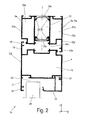
- Fig. 2 the door is off Fig. 1 shown in section. For simplicity, only a horizontally extending section is shown.
- the horizontally extending sash 8 of the sash 2 is executed here from a thermally unseparated profile 4.
- the thermally unseparated profile 4 has a T-shaped cross-section with the "T" turned 90 degrees to the left.
- the profile has a central hollow chamber 15.
- the thermally unseparated profile 4 also has two webs 16, 17, whose free ends each have a groove 18, 19, each receiving a sealing profile (not shown here).
- the thermally unseparated profile 4 also has a fold 23 into which the filling 20 is inserted.
- the fold 23 has a groove 21 into which a retaining strip 22 is inserted.
- the thermally unseparated profile 4 is preferably made of a metal, particularly preferably made of an aluminum material by extrusion.
- Blendrahmenholm 14a of the frame 3a is made here of a composite profile 5a.
- the composite profile 5a has a first partial profile 24a, in which in this case at least one hollow chamber 26a is formed, and a second partial profile 25a, in which also preferably at least one hollow chamber 27a is formed.
- the metallic profiles 24a, 25a can alternatively also be designed without pronounced hollow chambers 26a, 27a or have a plurality of hollow chambers.
- the first partial profile 24a is connected to the second partial profile 25a via at least one or more insulating webs 28a (aligned parallel here). These insulating webs 28a between the first part profile 24a and the second part profile 25a form a first insulating land zone I or plane.
- the insulating webs 28a here-exemplarily- no hollow chamber.
- the insulating webs 28a but also have one or more hollow chambers or the insulating webs 28a may be summarized by transverse webs to a kind of superior insulating profile.
- the insulating webs 28a of Isolierstegzone I are here-purely exemplary- in a plane. Alternatively, it is also possible for the insulating webs 28a of the insulating web zone I to be arranged vertically and / or horizontally offset from each other.
- the first and second partial profile 24a, 25a are preferably produced as extruded aluminum profiles. Alternatively, the production is also possible from a different material such as steel and / or another manufacturing method.
- the insulating webs 28a are made of a plastic material, so that in each case a substantial thermal separation between the sub-profiles 24a, 25a is achieved.
- the insulating webs 28a are web-shaped in cross-section and have thickened end portions 29.
- each of the end portions 29 engages in a corresponding groove 30 of each one of the sub-profiles 24a, 25a, wherein the groove walls, the thickened end portions 29 of the insulating webs 28a in the x and y directions (see coordinate system in Fig. 2 ) preferably engage positively.
- the respective end portion 29 preferably has a trapezoidal or triangular or wedge-shaped or L-shaped or rectangular cross-section.
- the respective groove 30 accordingly has a cross section with a corresponding cross section.
- the respective end sections 29 are fixed in the respective groove 30 by a forming process and / or with a wire (not shown here) ), which has an outer structure, such as a knurling, which the shear strength in the profile direction (perpendicular to the plane of the Fig. 2 ) elevated.
- the end sections can also be inserted into the groove 30 with a suitable joining method without wire or the like.
- the first sub-profile 24a is preferably separated from the second sub-profile 25a by a hollow chamber 31 which is formed in the first insulating land zone I between the two insulating webs 28a and the adjacent metal profiles 24a, 25a.
- a number of hollow chambers 26a, 31, and 27a are formed, which provide good thermal insulation.
- the second partial profile 25a has a web 32a, wherein at the end of the web 32a a groove 33a for receiving a seal (not shown here) is provided.
- the invention is based on the in Fig. 2 illustrated variant, but also on a composite profile 5b feasible, in which two partial profiles 24b, 25b (inner profile and outer profile) and a metallic center profile 35 (not shown here) via two Isolierstegzonen I, II are connected to one or more insulating webs 28b.
- Fig. 3 an embodiment of the door 1 is shown.
- the horizontally extending frame spar 14b of the frame 3b is made here of a composite profile 5b.
- the composite profile 5b has a first partial profile 24b, in which in this case at least one hollow chamber 26b is formed, and a second partial profile 25b, in which also preferably at least one hollow chamber 27b is formed.
- the composite profile 5b has a metallic center profile 35, in which also preferably at least one hollow chamber 36 is formed.
- the metallic profiles 24b, 25b, 35 may alternatively be designed without pronounced hollow chambers 26b, 27b, 36 or have a plurality of hollow chambers.
- the first part profile 24b is connected to the center profile 35 via at least one or more insulating webs 28b (here aligned in parallel and arranged horizontally slightly offset). These insulating webs 28b between the first part profile 24b and the middle profile 35 form a first insulating land zone I or plane.
- the central profile 35 is connected to the second partial profile 24b via at least one or more insulating webs 28b (here aligned in parallel and arranged horizontally slightly offset). These insulating webs 28b between the first part profile 24b and the middle profile 35 form a second insulating land zone II or plane.
- the first and second partial profile 24b, 25b and the middle profile 35 are preferably produced as extruded aluminum profiles. Alternatively, the production is also possible from a different material such as steel and / or another manufacturing method.
- the insulating webs 28b are made of a plastic material, so that in each case a substantial thermal separation between the sub-profiles 24b, 25b and the central profile 35 is achieved.
- the first sub-profile 24b is preferably separated from the center profile 35 by a hollow chamber 37 which is formed in the first insulating land zone I between the two insulating webs 28b and the adjacent metal profiles 24b, 35b.
- the second sub-profile 25b is preferably separated from the middle profile 35 by a hollow chamber 38 which is formed in the first insulating land zone II between the two insulating webs 28b and the adjacent metal profiles 25b, 35b.
- the second sub-profile 25b has a web 32b, wherein at the end of the web 32b, a groove 33b for receiving a seal (not shown) is provided.
- the fold region 34a, 34b is not represented by the seals here), for which the grooves 18 or 33a, 33b are provided, sealed against the environment.
- the window frame 3 a, 3 b is designed to be thermally separated from the casement 2, so that no temperatures above 140 ° occur on the side of the door 1 a, 1 b facing away from the fire.
- the construction described which is to be used preferably for fire doors, is characterized in an advantageous manner by a significant cost advantage, as can be dispensed with expensive multi-point locks and a correspondingly complex installation.
- the majority of these doors (about 90%) is anyway installed in the interior of buildings, so that the disadvantages of a thermally unseparated construction, as they occur in an arrangement of such doors in the building envelope, hardly or not come to fruition.
Landscapes
- Engineering & Computer Science (AREA)
- Civil Engineering (AREA)
- Structural Engineering (AREA)
- Special Wing (AREA)
Abstract
Description
- Die vorliegende Erfindung betrifft eine Tür oder ein Fenster mit Brandschutzeigenschaften nach dem Oberbegriff des Anspruchs 1.
- Derartige Türen oder Fenster mit Brandschutzeigenschaften sind aus dem Stand der Technik bekannt.
- Verbundprofile bestehen aus mindestens einem metallischen Außenprofil und einem metallischen Innenprofil, die durch mindestens ein den Wärmedurchgang reduzierendes Element, zum Beispiel ein Isoliersteg, miteinander verbunden sind. Nachteilig bei derartigen Verbundprofilen ist, dass sich diese bei unterschiedlichen Temperaturen auf der Innen- und Außenseite eines aus ihnen aufgebauten Bauelements, beispielsweise einer Tür, verbiegen. Diese Erscheinung wird üblicherweise als sogenannter Bimetalleffekt bezeichnet.
- Durch diesen Bimetalleffekt kann es leicht zu Undichtigkeiten kommen, die insbesondere auch bei Brandschutzkonstruktionen unbedingt vermieden werden müssen. Um das Problem des Bimetalleffektes auszuräumen, sind bereits zahlreiche Lösungen vorgeschlagen worden. Eine Lösung, die sich besonders bewährt hat, wird in der
EP 0 829 609 B1 beschrieben. - Brandschutzkonstruktionen aus thermisch getrennten Profilkonstruktionen, sind ebenfalls seit langem bekannt. So wird beispielsweise in der
EP 0 717 165 B1 ein Profilsystem in Brandschutzausführung beschrieben, das aus einem Metallprofil besteht, dass einen Mittelbereich aufweist, in dem der Wärmefluss gegenüber den Außenbereichen herabgesetzt ist. Nachteilig bei derartigen Brandschutzkonstruktionen ist, dass sich diese im Brandfall, also bei unterschiedlichen Temperaturen auf der Innen- und Außenseite), ebenfalls verbiegen. Auch hier stellt sich ursächlich durch die Temperaturentwicklung im Brandfall also der sogenannte Bimetalleffekt ein. Durch den Bimetalleffekt kann es bei Brandschutzkonstruktionen sogar zum Flammendurchschlag durch ein entsprechendes Bauelement, wie z.B. einer Tür kommen. Um hier Abhilfe zu schaffen, werden die Flügelrahmen mehrfach verriegelt, um so die Durchbiegung zu verhindern. Zusätzlich werden in den Kammern zwischen den Elementen (Blendrahmen/Flügelrahmen) Brandschutzmaterialien eingesetzt, die bei entsprechender Temperaturbeaufschlagung mit einer endothermen Reaktion reagieren bzw. aufschäumen und dadurch verhindern, heiße Gase oder Flammen durch die Kammern dringen. - Sowohl der Einsatz von besonderen Dämmprofilen aus Brandschutzmaterialien, wie auch die Verwendung von Mehrfach-Verriegelungen sind aufwändig und damit teuer und darüber hinaus reparaturanfällig.
- Die Erfindung hat ausgehend von diesem Stand der Technik demnach die Aufgabe, eine Tür oder ein Fenster mit Brandschutzeigenschaften zu schaffen, die / das die oben genannten Nachteile, insbesondere den Bimetalleffekt der Profile, sowohl unter Umgebungstemperaturen, wie auch im Brandfall zumindest signifikant verringert. Brandschutz bedeutet zumindest ein Einhalten eines Brandschutzes 30 Minuten (T 30).
- Die vorliegende Erfindung löst dieses Problem durch den Gegenstand des Anspruchs 1.
- Demnach ist erfindungsgemäß vorgesehen, dass zumindest einer der vertikalen Flügelrahmenholme aus einem thermisch nicht getrennten Profil hergestellt ist. Ein thermisch nicht getrenntes Profil ist vorzugsweise ein aus Metall oder einer Metalllegierung hergestelltes Profil, bei dem nicht zwei oder mehr Metall-Profile bzw. - schalen durch einen oder mehrere Isolierstege getrennt sind bzw. bei dem nicht einer oder mehrere Isolierprofile die Metallprofile eines Verbundprofils voneinander trennen.
- Der Erfindung verzichtet bewusst auf die Vorteile einer thermischen Trennung im Flügelrahmen, um die größeren Vorteile einer erfindungsgemäßen Konstruktion für Türen oder Fenster mit Brandschutzeigenschaften -nämlich die Vermeidung des Bimetalleffektes im Brandfall- zu erhalten. Unter Türen oder Fenster mit Brandschutzeigenschaften werden solche verstanden, die mindestens die Norm T-30 (Brandschutz- bzw. Feuerschutzklasse) oder mehr einhalten.
- Durch eine erfindungsgemäße Gestaltung einer Tür oder eines Fensters mit Brandschutzeigenschaften mit einem Flügelrahmen ohne oder mit nur teilweiser thermischen Trennung und einen Blendrahmen mit thermischer Trennung kann in besonders einfacher und damit vorteilhafter Weise auf eine teure und aufwändig zu montierende Verriegelungen und/ oder auf besondere Dämmprofile mit Brandschutzeigenschaften verzichtet werden.
- Die beschriebene Konstruktion, die für Brandschutztüren oder -fenster zum Einsatz kommen soll, kennzeichnet sich somit in vorteilhafter Weise durch einen erheblichen Kostenvorteil im Vergleich zum Stand der Technik, da auf teure Mehrfachverriegelungen und eine entsprechend aufwändige Montage verzichtet werden kann.
- Weitere vorteilhafte Ausführungen der Erfindung sind den Unteransprüchen zu entnehmen.
- Ausführungsbeispiele des erfindungsgemäßen Gegenstandes sind in den Zeichnungen dargestellt und werden im Folgenden näher beschrieben. Es zeigt:
- Figur 1:
- eine Vorderansicht einer Tür;
- Figur 2:
- eine Seitenansicht im Schnitt der Tür aus
Fig. 1 ; - Figur 3:
- eine Seitenansicht im Schnitt einer Ausführungsvariante der Tür aus
Fig. 1 . - Die
Fig. 1 zeigt eine Tür 1 a, 1 b mit Brandschutzeigenschaften, die einen Flügelrahmen 2 und einen Blendrahmen 3a, 3b aufweist. Dies ist lediglich rein beispielhaft zu verstehen. Alternativ zu der inFig. 1 dargestellten Tür 1 a, 1 b kann die vorliegende Erfindung auch bei Fenstern oder anderen Bauelementen zur Anwendung kommen. - Für die vorliegende Erfindung ist insbesondere der Aufbau des beweglichen Flügelrahmens 2 von Bedeutung. Der Flügelrahmen 2 weist einen vertikalen Flügelrahmenholm 6 auf der Griffseite sowie einen weiteren vertikalen Flügelrahmenholm 7 auf der Bandseite auf. Darüber hinaus weist der Flügelrahmen 2 ein oberen horizontalen Flügelrahmenholm 8 sowie einen unteren horizontalen Flügelrahmenholm 9 auf. Der untere horizontale Flügelrahmenholm 9 kann aus einem sogn. Sockelprofil hergestellt sein, es kann aber auch das gleiche Profil wie bei den übrigen Flügelrahmenholmen 6, 7, 8 verwendet werden. Die Flügelrahmenholme 6, 7, 8 sind zu dem Flügelrahmen 2 zusammengefügt, so dass in den Flügelrahmen 2 eine sogn. Füllung 20 eingesetzt werden kann. Der Blendrahmen 3a, 3b dieser Tür 1 ist mit Seitenteilen 10, 11 ausgestattet und weist Blendrahmenholme 12a, 12b, 13a, 13b, 14a, 14b auf.
- Erfindungsgemäß wird mindestens der vertikale Flügelrahmenholm 6 auf der Griffseite aus einem thermisch ungetrennten Profil 4 ausgebildet. Vorzugsweise wird auch der zweite vertikal Flügelrahmenholm 7 auf der Bandseite aus dem thermisch ungetrennten Profil 4 ausgebildet, besonders bevorzugt wird zusätzlich der obere horizontale Flügelrahmenholm 8 und ganz besonders bevorzugt alle vier Flügelrahmenholme 6, 7, 8, 9 aus dem thermisch ungetrennten Profil 4 ausgeführt. Durch eine solche Ausführung der Flügelrahmenholme 6, 7, 8, 9 wird ein Bimetalleffekt beim Flügelrahmen bei einseitiger Temperaturbeaufschlagung ausgeschlossen oder prägt sich nur unwesentlich aus.
- In
Fig. 2 ist die Tür ausFig. 1 im Schnitt dargestellt. Zur Vereinfachung ist nur ein horizontal verlaufender Abschnitt dargestellt. Der waagerecht verlaufende Flügelrahmenholm 8 des Flügelrahmens 2 ist hier aus einem thermisch ungetrennten Profil 4 ausgeführt. - Das thermisch ungetrennte Profil 4 weist einen T-förmigen Querschnitt auf, wobei das "T" um 90° nach links gedreht ist. Das Profil weist eine zentrale Hohlkammer 15 auf. Das thermisch ungetrennte Profil 4 weist weiterhin zwei Stege 16, 17 auf, deren freien Enden jeweils eine Nut 18, 19 aufweist, die jeweils ein Dichtungsprofil (hier nicht dargestellt) aufnehmen. Das thermisch ungetrennte Profil 4 weist ferner einen Falz 23 auf, in den die Füllung 20 eingesetzt ist. Der Falz 23 weist eine Nut 21 auf, in die eine Halteleiste 22 eingesetzt ist. Das thermisch ungetrennte Profil 4 ist vorzugsweise aus einem Metall, besonders bevorzugt aus einem Aluminiumwerkstoff im Strangpressverfahren hergestellt.
- Besonders vorteilhaft ist, dass die Profilkontur eines thermisch ungetrennten Flügelrahmenprofils 4 mit der der Kontur eines thermisch getrennten Flügelprofils (hier nicht dargestellt) entspricht, insbesondere wenn diese über Gehrungsecken miteinander verbunden werden, z. B. wenn nicht alle vier Flügelrahmenholme 6, 7, 8, 9 thermisch ungetrennt ausgeführt sind.
- Der waagerecht verlaufende Blendrahmenholm 14a des Blendrahmens 3a ist hier aus einem Verbundprofil 5a ausgeführt.
- Das Verbundprofil 5a weist ein erstes Teilprofil 24a, auf, in welchem hier wenigstens eine Hohlkammer 26a ausgebildet ist, sowie ein zweites Teilprofil 25a, in dem ebenfalls vorzugsweise wenigstens eine Hohlkammer 27a ausgebildet ist. Die metallischen Profile 24a, 25a können alternativ auch ohne ausgeprägte Hohlkammern 26a, 27a, ausgeführt sein oder mehrere Hohlkammern aufweisen.
- Das erste Teilprofil 24a ist mit dem zweiten Teilprofil 25a über wenigstens einen oder mehrere Isolierstege 28a (hier parallel ausgerichtet) verbunden. Diese Isolierstege 28a zwischen dem ersten Teilprofil 24a und dem zweiten Teilprofil 25a bilden eine erste Isolierstegzone I bzw. -ebene.
- Die Isolierstege 28a weisen hier -rein beispielhaft- keine Hohlkammer auf. Alternativ können die Isolierstege 28a aber auch eine oder mehrere Hohlkammern aufweisen oder die Isolierstege 28a können durch Querstege zu einer Art übergeordnetem Isolierprofil zusammengefasst sein.
- Die Isolierstege 28a der Isolierstegzone I liegen hier -rein beispielhaft- in einer Ebene. Alternativ ist es auch möglich, dass die Isolierstege 28a der Isolierstegzone I jeweils vertikal und oder horizontal zueinander versetzt angeordnet sind.
- Das erste und zweite Teilprofil 24a, 25a sind vorzugsweise als stranggepresste Aluminiumprofile hergestellt. Alternativ ist die Herstellung auch aus einem anderen Werkstoff wie Stahl und/oder einem anderen Fertigungsverfahren möglich. Die Isolierstege 28a sind aus einem Kunststoffwerkstoff hergestellt, so dass jeweils eine weitgehende thermische Trennung zwischen den Teilprofilen 24a, 25a erreicht wird.
- Vorzugsweise sind die Isolierstege 28a im Querschnitt stegförmig ausgebildet und weisen verdickte Endabschnitte 29 auf. Vorzugsweise greift dabei jeder der Endabschnitte 29 in eine korrespondierende Nut 30 von jeweils einem der Teilprofile 24a, 25a ein, wobei die Nutwände die verdickten Endabschnitte 29 der Isolierstege 28a in x- und y-Richtung (siehe Koordinatensystem in
Fig. 2 ) vorzugsweise formschlüssig umgreifen. Der jeweilige Endabschnitt 29 weist vorzugsweise einen trapezförmigen oder dreieck- bzw. keilförmigen oder L-förmigen oder rechteckigen Querschnitt auf. Die jeweilige Nut 30 weist dementsprechend einen Querschnitt mit jeweils korrespondierendem Querschnitt auf. - Um eine schubfeste und damit zusätzlich kraftschlüssige Verbindung zwischen dem jeweiligen Endabschnitt 29 und der jeweiligen Nut 30 zu erhalten, ist es vorteilhaft, wenn die jeweiligen Endabschnitte 29 in die jeweilige Nut 30 durch ein Umformverfahren festgelegt ist und / oder mit einem Draht (hier nicht dargestellt) festgesetzt sind, der eine Außenstruktur, wie z.B. eine Rändelung aufweist, was die Schubfestigkeit in Profilrichtung (senkrecht zur Zeichenebene der
Fig. 2 ) erhöht. Die Endabschnitte können aber alternativ auch mit einem geeigneten Fügeverfahren ohne Draht oder dgl. in die Nut 30 eingesetzt sein. - Das erste Teilprofil 24a ist von dem zweiten Teilprofil 25a vorzugsweise über eine Hohlkammer 31 getrennt, die in der ersten Isolierstegzone I zwischen den beiden Isolierstegen 28a und den angrenzenden Metallprofilen 24a, 25a ausgebildet wird. Dadurch sind von einer Außenseite des ersten Teilprofils 24a zu einer zweiten Außenseite des zweiten metallischen Außenprofils 25a eine Reihe von Hohlkammern 26a, 31, und 27a ausgebildet, die für eine gute Wärmedämmung sorgen. Das zweite Teilprofil 25a weist einen Steg 32a auf, wobei endseitig an dem Steg 32a eine Nut 33a zur Aufnahme einer Dichtung (hier nicht dargestellt) vorgesehen ist.
- Die Erfindung ist auf die in
Fig. 2 dargestellte Variante nicht beschränkt, sondern auch an einem Verbundprofil 5b realisierbar, bei dem zwei Teilprofile 24b, 25b (Innenprofil und Außenprofil) und ein metallisches Mittelprofil 35 (hier nicht dargestellt) über zwei Isolierstegzonen I, II mit einem oder mehreren Isolierstegen 28b verbunden sind. - In
Fig. 3 ist eine Ausführungsvariante der Tür 1 dargestellt. Der waagerecht verlaufende Blendrahmenholm 14b des Blendrahmens 3b ist hier aus einem Verbundprofil 5b ausgeführt. - Um Wiederholungen zu vermeiden, werden im Folgenden nur Abweichungen bzw. Änderungen und Ergänzungen zu der oben beschriebenen Ausführungsvariante eines erfindungsgemäßen Verbundprofils 5a nach
Fig. 2 beschrieben. - Das Verbundprofil 5b weist ein erstes Teilprofil 24b, auf, in welchem hier wenigstens eine Hohlkammer 26b ausgebildet ist, sowie ein zweites Teilprofil 25b, in dem ebenfalls vorzugsweise wenigstens eine Hohlkammer 27b ausgebildet ist. Darüber hinaus weist das Verbundprofil 5b ein metallisches Mittelprofil 35 auf, in dem ebenfalls vorzugsweise wenigstens eine Hohlkammer 36 ausgebildet ist. Die metallischen Profile 24b, 25b, 35 können alternativ auch ohne ausgeprägte Hohlkammern 26b, 27b, 36 ausgeführt sein oder mehrere Hohlkammern aufweisen.
- Das erste Teilprofil 24b ist mit dem Mittelprofil 35 über wenigstens einen oder mehrere Isolierstege 28b (hier parallel ausgerichtet und horizontal leicht versetzt angeordnet) verbunden. Diese Isolierstege 28b zwischen dem ersten Teilprofil 24b und dem Mittelprofil 35 bilden eine erste Isolierstegzone I bzw. -ebene.
- Das Mittelprofil 35 ist mit dem zweiten Teilprofil 24b über wenigstens einen oder mehrere Isolierstege 28b (hier parallel ausgerichtet und horizontal leicht versetzt angeordnet) verbunden. Diese Isolierstege 28b zwischen dem ersten Teilprofil 24b und dem Mittelprofil 35 bilden eine zweite Isolierstegzone II bzw. -ebene.
- Das erste und zweite Teilprofil 24b, 25b sowie das Mittelprofil 35 sind vorzugsweise als stranggepresste Aluminiumprofile hergestellt. Alternativ ist die Herstellung auch aus einem anderen Werkstoff wie Stahl und/oder einem anderen Fertigungsverfahren möglich. Die Isolierstege 28b sind aus einem Kunststoffwerkstoff hergestellt, so dass jeweils eine weitgehende thermische Trennung zwischen den Teilprofilen 24b, 25b und dem Mittelprofil 35 erreicht wird.
- Das erste Teilprofil 24b ist von dem Mittelprofil 35 vorzugsweise über eine Hohlkammer 37 getrennt, die in der ersten Isolierstegzone I zwischen den beiden Isolierstegen 28b und den angrenzenden Metallprofilen 24b, 35 ausgebildet wird. Das zweite Teilprofil 25b ist von dem Mittelprofil 35 vorzugsweise über eine Hohlkammer 38 getrennt, die in der ersten Isolierstegzone II zwischen den beiden Isolierstegen 28b und den angrenzenden Metallprofilen 25b, 35 ausgebildet wird.
- Dadurch sind von einer Außenseite des ersten Teilprofils 24b zu einer zweiten Außenseite des zweiten Teilprofils 25b eine Reihe von Hohlkammern 26b, 37, 36, 38 und 27b ausgebildet, die für eine gute Wärmedämmung sorgen. Das zweite Teilprofil 25b weist einen Steg 32b auf, wobei endseitig an dem Steg 32b eine Nut 33b zur Aufnahme einer Dichtung (hier nicht dargestellt) vorgesehen ist.
- Das thermisch nicht getrennte Profil 4 des Flügelrahmens 2 und das Verbundprofil 5a, 5b des Blendrahmens 3a, 3b bilden im geschlossenen Zustand der Tür 1 einen Falzbereich 34a, 34b. Der Falzbereich 34a, 34b wird durch die Dichtungen hier nicht dargestellt), für die die Nuten 18 bzw. 33a, 33b vorgesehen sind, gegen die Umgebung abgedichtet.
- Erfindungsgemäß ist der Blendrahmen 3a, 3b zum Flügelrahmen 2 thermisch getrennt ausgeführt, so dass auf der brandabgewandten Seite der Tür 1 a, 1 b keine Temperaturen über 140° auftreten.
- Die beschriebene Konstruktion, die vorzugsweise für Brandschutztüren zum Einsatz kommen soll, kennzeichnet sich in vorteilhafter Weise durch einen erheblichen Kostenvorteil aus, da auf teure Mehrfachverriegelungen und eine entsprechend aufwändige Montage verzichtet werden kann. Der überwiegende Teil dieser Türen (ca. 90 %) wird ohnehin im Innenbereich von Gebäuden installiert, so dass die Nachteile einer thermisch ungetrennten Konstruktion, wie sie bei einer Anordnung solcher Türen in der Gebäudehülle auftreten, kaum bzw. nicht zum Tragen kommen.
-
- 1a, 1b
- Tür
- 2
- Flügelrahmen
- 3a, 3b
- Blendrahmen
- 4
- Profil
- 5a, 5b
- Verbundprofil
- 6
- Flügelrahmenholm
- 7
- Flügelrahmenholm
- 8
- Flügelrahmenholm
- 9
- Flügelrahmenholm
- 10
- Seitenteil
- 11
- Seitenteil
- 12a, 12b
- Blendrahmenholm
- 13a, 13b
- Blendrahmenholm
- 14a, 14b
- Blendrahmenholm
- 15
- Hohlkammer
- 16
- Steg
- 17
- Steg
- 18
- Nut
- 19
- Nut
- 20
- Füllung
- 21
- Nut
- 22
- Halteleiste
- 23
- Falz
- 24a, 24b
- Teilprofil
- 25a, 25b
- Teilprofil
- 26a, 26b
- Hohlkammer
- 27a, 27b
- Hohlkammer
- 28a, 28b
- Isoliersteg
- 29
- Endabschnitt
- 30
- Nut
- 31
- Hohlkammer
- 32a, 32b
- Steg
- 33a, 33b
- Nut
- 34a, 34b
- Falzbereich
- 35
- Mittelprofil
- 36
- Hohlkammer
- 37
- Hohlkammer
- 38
- Hohlkammer
- I
- Isolierstegebene
- II
- Isolierstegebene
Claims (10)
- Tür (1 a, 1 b) oder Fenster mit Brandschutzeigenschaften, wobei die Tür (1 a, 1 b) oder das Fenster mit einem Blendrahmen (3a, 3b) und einem Flügelrahmen (2), wobei der Flügelrahmen (2) aus Flügelrahmenholmen (6, 7, 8, 9) aufgebaut ist und die Flügelrahmenholme (6, 7, 8, 9) jeweils aus einem Abschnitt eines Profils hergestellt sind und wobei der Blendrahmen (3a, 3b) aus Blendrahmenholmen (12a, 12b, 13a, 13b, 14a, 14b) aufgebaut ist und die Blendrahmenholme (12a, 12b, 13a, 13b, 14a, 14b) jeweils aus einem Abschnitt eines Verbundprofils (5a, 5b) hergestellt sind, wobei am Flügelrahmen (2) ein Falz (23) ausgebildet ist, in den eine Füllung (20) einsetzbar ist, dadurch gekennzeichnet, dass zumindest einer der vertikalen Flügelrahmenholme (6, 7) aus einem thermisch nicht getrennten Profil (4) hergestellt ist.
- Tür (1a, 1 b) oder Fenster nach Anspruch 1, dadurch gekennzeichnet, dass beide vertikalen Flügelrahmenholme (6, 7) aus dem thermisch nicht getrennten Profil (4) hergestellt sind.
- Tür (1a, 1 b) oder Fenster nach Anspruch 1 oder Anspruch 2, dadurch gekennzeichnet, dass beide vertikalen Flügelrahmenholme (6, 7) und ein waagerechter Flügelrahmenholm (8) aus dem thermisch nicht getrennten Profil (4) hergestellt sind.
- Tür (1 a, 1 b) oder Fenster nach einem der vorgenannten Ansprüche, dadurch gekennzeichnet, dass sämtliche Flügelrahmenholme (6, 7, 8, 9) aus dem thermisch nicht getrennten Profil (4) hergestellt sind.
- Tür (1a, 1 b) oder Fenster nach einem der vorgenannten Ansprüche, dadurch gekennzeichnet, dass das Verbundprofil (5a) aus einem ersten Teilprofil (24a) und einem zweiten Teilprofil (25a) aufgebaut ist, die jeweils durch Isolierstege (28a) beabstandet miteinander verbunden sind.
- Tür (1 a, 1 b) oder Fenster nach einem der vorgenannten Ansprüche, dadurch gekennzeichnet, dass das Verbundprofil (5b) aus einem ersten Teilprofil (24a), einem Mittelprofil (35) und einem zweiten Teilprofil (25b) aufgebaut ist, die jeweils durch Isolierstege (28b) beabstandet miteinander verbunden sind.
- Tür (1 a, 1 b) oder Fenster nach einem der vorgenannten Ansprüche, dadurch gekennzeichnet, dass das Verbundprofil (5a, 5b) jeweils mehrere Hohlkammern (26a, 31, 27a) bzw. (26b, 37, 36, 38, 27b) aufweist.
- Tür (1 a, 1 b) oder Fenster nach einem der vorgenannten Ansprüche, dadurch gekennzeichnet, dass das thermisch nicht getrennten Profil (4), das erste Teilprofil (24a, 24b), das Mittelprofil (35) und das zweite Teilprofil (25a, 25b) jeweils zumindest eine Hohlkammer (26a, 26b, 36, 27a, 27b) aufweist.
- Tür (1 a, 1 b) oder Fenster nach einem der vorgenannten Ansprüche, dadurch gekennzeichnet, dass das thermisch nicht getrennte Profil (4), das erste Teilprofil (24a, 24b), das Mittelprofil (35) und das zweite Teilprofil (25a, 25b) jeweils aus einem Metall, bevorzugt aus einem Aluminiumwerkstoff im Strangpressverfahren hergestellt sind.
- Tür (1 a, 1 b) oder Fenster nach einem der vorgenannten Ansprüche, dadurch gekennzeichnet, dass das die Isolierstege (28a, 28b) jeweils aus einem Kunststoffwerkstoff hergestellt sind.
Priority Applications (1)
| Application Number | Priority Date | Filing Date | Title |
|---|---|---|---|
| PL15182151T PL2990581T3 (pl) | 2014-08-25 | 2015-08-24 | Drzwi lub okno o własnościach przeciwpożarowych |
Applications Claiming Priority (1)
| Application Number | Priority Date | Filing Date | Title |
|---|---|---|---|
| DE102014112107.4A DE102014112107A1 (de) | 2014-08-25 | 2014-08-25 | Tür oder Fenster mit Brandschutzeigenschaften |
Publications (2)
| Publication Number | Publication Date |
|---|---|
| EP2990581A1 true EP2990581A1 (de) | 2016-03-02 |
| EP2990581B1 EP2990581B1 (de) | 2022-01-26 |
Family
ID=53969272
Family Applications (1)
| Application Number | Title | Priority Date | Filing Date |
|---|---|---|---|
| EP15182151.9A Active EP2990581B1 (de) | 2014-08-25 | 2015-08-24 | Tür oder fenster mit brandschutzeigenschaften |
Country Status (3)
| Country | Link |
|---|---|
| EP (1) | EP2990581B1 (de) |
| DE (1) | DE102014112107A1 (de) |
| PL (1) | PL2990581T3 (de) |
Cited By (1)
| Publication number | Priority date | Publication date | Assignee | Title |
|---|---|---|---|---|
| EP4424968A1 (de) | 2023-03-01 | 2024-09-04 | SCHÜCO International KG | Verbundprofil, rahmen und verfahren zur herstellung des verbundprofils |
Citations (3)
| Publication number | Priority date | Publication date | Assignee | Title |
|---|---|---|---|---|
| DE8505873U1 (de) * | 1985-03-01 | 1986-03-27 | Nahr, Helmar, Dr.Dr., 8530 Neustadt | Wärmegedämmtes Fenster oder entsprechende, verglaste Tür |
| EP0717165B1 (de) | 1994-12-08 | 1999-05-12 | SCHÜCO International KG | Rahmenwerk aus Metallprofilen in Brandschutzausführung für Fenster, Türen, Fassaden oder Glasdächer |
| EP0829609B1 (de) | 1996-09-17 | 2001-05-09 | SCHÜCO International KG | Wärmegedämmtes Verbundprofil für Türen, Fenster oder Fassaden |
Family Cites Families (3)
| Publication number | Priority date | Publication date | Assignee | Title |
|---|---|---|---|---|
| IT7921463U1 (it) * | 1979-05-02 | 1980-11-02 | Fonderia Elett Alluminio E Leghe F E A L Spa | Serramento in alluminio con taglio termico a scudo e giunto aperto, particolarmente per telai di porte e finestre |
| DE19848570C1 (de) * | 1998-10-21 | 2000-03-16 | Evg Bauprofil System Entwicklungs & Vermarktungsgesellschaft Mbh | Rauchschutzprofil |
| DE102005057389B3 (de) * | 2005-11-30 | 2007-08-16 | Hydro Building Systems Gmbh | Gebäudeelement in brandgeschützter Ausführung |
-
2014
- 2014-08-25 DE DE102014112107.4A patent/DE102014112107A1/de not_active Withdrawn
-
2015
- 2015-08-24 PL PL15182151T patent/PL2990581T3/pl unknown
- 2015-08-24 EP EP15182151.9A patent/EP2990581B1/de active Active
Patent Citations (3)
| Publication number | Priority date | Publication date | Assignee | Title |
|---|---|---|---|---|
| DE8505873U1 (de) * | 1985-03-01 | 1986-03-27 | Nahr, Helmar, Dr.Dr., 8530 Neustadt | Wärmegedämmtes Fenster oder entsprechende, verglaste Tür |
| EP0717165B1 (de) | 1994-12-08 | 1999-05-12 | SCHÜCO International KG | Rahmenwerk aus Metallprofilen in Brandschutzausführung für Fenster, Türen, Fassaden oder Glasdächer |
| EP0829609B1 (de) | 1996-09-17 | 2001-05-09 | SCHÜCO International KG | Wärmegedämmtes Verbundprofil für Türen, Fenster oder Fassaden |
Cited By (2)
| Publication number | Priority date | Publication date | Assignee | Title |
|---|---|---|---|---|
| EP4424968A1 (de) | 2023-03-01 | 2024-09-04 | SCHÜCO International KG | Verbundprofil, rahmen und verfahren zur herstellung des verbundprofils |
| DE102023105033A1 (de) | 2023-03-01 | 2024-09-05 | SCHÜCO International KG | Verbundprofil, Rahmen und Verfahren zur Herstellung des Verbundprofils |
Also Published As
| Publication number | Publication date |
|---|---|
| DE102014112107A1 (de) | 2016-02-25 |
| PL2990581T3 (pl) | 2022-06-13 |
| EP2990581B1 (de) | 2022-01-26 |
Similar Documents
| Publication | Publication Date | Title |
|---|---|---|
| EP0829609B1 (de) | Wärmegedämmtes Verbundprofil für Türen, Fenster oder Fassaden | |
| EP3140485B1 (de) | Verbundprofil für türen, fenster oder fassadenelemente | |
| CH649809A5 (de) | Aluminium-verbundprofil und mit diesem hergestellte fenster- oder tuerkonstruktion. | |
| EP4495366B1 (de) | Verbundkonstruktion für feststehende und bewegbare flächenelemente | |
| DE1509553A1 (de) | Fensterkonstruktion | |
| EP3246505B1 (de) | Verbundprofil für türen, fenster oder fassadenelemente | |
| DE19635409A1 (de) | Glastür für Brandschutzzwecke sowie Verfahren zum Herstellen einer Glastür für Brandschutzzwecke | |
| EP2363567B1 (de) | Rahmen eines Kunststofffensters oder einer Kunststofftür | |
| CH648380A5 (de) | Fluegel- und blendrahmen fuer fenster oder verglaste tueren. | |
| EP1965011A2 (de) | Fensterprofil | |
| EP2990581B1 (de) | Tür oder fenster mit brandschutzeigenschaften | |
| EP1650394B1 (de) | Fenster oder Türe | |
| EP3140483B1 (de) | Verbundprofil für türen, fenster oder fassadenelemente | |
| EP2530230A2 (de) | Isoliersteg für Fenster- und Türrahmen | |
| EP3423659B1 (de) | Verbundprofil für eine tür, ein fenster oder ein fassadenelement sowie verfahren zur herstellung des verbundprofils | |
| EP3140484B1 (de) | Verbundprofil für türen, fenster oder fassadenelemente | |
| DE102014112145A1 (de) | Verbundprofil für Türen, Fenster oder Fassadenelemente | |
| DE20100618U1 (de) | Rahmenprofil | |
| EP2039866A2 (de) | Flügelrahmen für Fenster und Türen | |
| DE102005021934A1 (de) | Rahmen für ein Fenster oder eine Tür | |
| EP4424968B1 (de) | Verbundprofil, rahmen und verfahren zur herstellung des verbundprofils | |
| EP4102021B1 (de) | Fenster- oder tür-hohlkammerprofil, system mit einem solchen hohlkammerprofil und daraus hergestellter rahmen | |
| DE102014112128A1 (de) | Verbundprofil für Türen, Fenster oder Fassadenelemente | |
| DE1183658B (de) | Vorhaengewand | |
| EP2942468A1 (de) | Verbundprofil für türen, fenster oder fassadenelemente |
Legal Events
| Date | Code | Title | Description |
|---|---|---|---|
| PUAI | Public reference made under article 153(3) epc to a published international application that has entered the european phase |
Free format text: ORIGINAL CODE: 0009012 |
|
| AK | Designated contracting states |
Kind code of ref document: A1 Designated state(s): AL AT BE BG CH CY CZ DE DK EE ES FI FR GB GR HR HU IE IS IT LI LT LU LV MC MK MT NL NO PL PT RO RS SE SI SK SM TR |
|
| AX | Request for extension of the european patent |
Extension state: BA ME |
|
| 17P | Request for examination filed |
Effective date: 20160812 |
|
| RBV | Designated contracting states (corrected) |
Designated state(s): AL AT BE BG CH CY CZ DE DK EE ES FI FR GB GR HR HU IE IS IT LI LT LU LV MC MK MT NL NO PL PT RO RS SE SI SK SM TR |
|
| GRAP | Despatch of communication of intention to grant a patent |
Free format text: ORIGINAL CODE: EPIDOSNIGR1 |
|
| STAA | Information on the status of an ep patent application or granted ep patent |
Free format text: STATUS: GRANT OF PATENT IS INTENDED |
|
| INTG | Intention to grant announced |
Effective date: 20211027 |
|
| GRAS | Grant fee paid |
Free format text: ORIGINAL CODE: EPIDOSNIGR3 |
|
| GRAA | (expected) grant |
Free format text: ORIGINAL CODE: 0009210 |
|
| STAA | Information on the status of an ep patent application or granted ep patent |
Free format text: STATUS: THE PATENT HAS BEEN GRANTED |
|
| AK | Designated contracting states |
Kind code of ref document: B1 Designated state(s): AL AT BE BG CH CY CZ DE DK EE ES FI FR GB GR HR HU IE IS IT LI LT LU LV MC MK MT NL NO PL PT RO RS SE SI SK SM TR |
|
| REG | Reference to a national code |
Ref country code: GB Ref legal event code: FG4D Free format text: NOT ENGLISH |
|
| REG | Reference to a national code |
Ref country code: CH Ref legal event code: EP |
|
| REG | Reference to a national code |
Ref country code: AT Ref legal event code: REF Ref document number: 1465428 Country of ref document: AT Kind code of ref document: T Effective date: 20220215 |
|
| REG | Reference to a national code |
Ref country code: IE Ref legal event code: FG4D Free format text: LANGUAGE OF EP DOCUMENT: GERMAN |
|
| REG | Reference to a national code |
Ref country code: DE Ref legal event code: R096 Ref document number: 502015015596 Country of ref document: DE |
|
| REG | Reference to a national code |
Ref country code: SE Ref legal event code: TRGR |
|
| REG | Reference to a national code |
Ref country code: NL Ref legal event code: FP |
|
| REG | Reference to a national code |
Ref country code: LT Ref legal event code: MG9D |
|
| PG25 | Lapsed in a contracting state [announced via postgrant information from national office to epo] |
Ref country code: RS Free format text: LAPSE BECAUSE OF FAILURE TO SUBMIT A TRANSLATION OF THE DESCRIPTION OR TO PAY THE FEE WITHIN THE PRESCRIBED TIME-LIMIT Effective date: 20220126 Ref country code: PT Free format text: LAPSE BECAUSE OF FAILURE TO SUBMIT A TRANSLATION OF THE DESCRIPTION OR TO PAY THE FEE WITHIN THE PRESCRIBED TIME-LIMIT Effective date: 20220526 Ref country code: NO Free format text: LAPSE BECAUSE OF FAILURE TO SUBMIT A TRANSLATION OF THE DESCRIPTION OR TO PAY THE FEE WITHIN THE PRESCRIBED TIME-LIMIT Effective date: 20220426 Ref country code: LT Free format text: LAPSE BECAUSE OF FAILURE TO SUBMIT A TRANSLATION OF THE DESCRIPTION OR TO PAY THE FEE WITHIN THE PRESCRIBED TIME-LIMIT Effective date: 20220126 Ref country code: HR Free format text: LAPSE BECAUSE OF FAILURE TO SUBMIT A TRANSLATION OF THE DESCRIPTION OR TO PAY THE FEE WITHIN THE PRESCRIBED TIME-LIMIT Effective date: 20220126 Ref country code: ES Free format text: LAPSE BECAUSE OF FAILURE TO SUBMIT A TRANSLATION OF THE DESCRIPTION OR TO PAY THE FEE WITHIN THE PRESCRIBED TIME-LIMIT Effective date: 20220126 Ref country code: BG Free format text: LAPSE BECAUSE OF FAILURE TO SUBMIT A TRANSLATION OF THE DESCRIPTION OR TO PAY THE FEE WITHIN THE PRESCRIBED TIME-LIMIT Effective date: 20220426 |
|
| PG25 | Lapsed in a contracting state [announced via postgrant information from national office to epo] |
Ref country code: LV Free format text: LAPSE BECAUSE OF FAILURE TO SUBMIT A TRANSLATION OF THE DESCRIPTION OR TO PAY THE FEE WITHIN THE PRESCRIBED TIME-LIMIT Effective date: 20220126 Ref country code: GR Free format text: LAPSE BECAUSE OF FAILURE TO SUBMIT A TRANSLATION OF THE DESCRIPTION OR TO PAY THE FEE WITHIN THE PRESCRIBED TIME-LIMIT Effective date: 20220427 Ref country code: FI Free format text: LAPSE BECAUSE OF FAILURE TO SUBMIT A TRANSLATION OF THE DESCRIPTION OR TO PAY THE FEE WITHIN THE PRESCRIBED TIME-LIMIT Effective date: 20220126 |
|
| PG25 | Lapsed in a contracting state [announced via postgrant information from national office to epo] |
Ref country code: IS Free format text: LAPSE BECAUSE OF FAILURE TO SUBMIT A TRANSLATION OF THE DESCRIPTION OR TO PAY THE FEE WITHIN THE PRESCRIBED TIME-LIMIT Effective date: 20220526 |
|
| REG | Reference to a national code |
Ref country code: DE Ref legal event code: R097 Ref document number: 502015015596 Country of ref document: DE |
|
| PG25 | Lapsed in a contracting state [announced via postgrant information from national office to epo] |
Ref country code: SM Free format text: LAPSE BECAUSE OF FAILURE TO SUBMIT A TRANSLATION OF THE DESCRIPTION OR TO PAY THE FEE WITHIN THE PRESCRIBED TIME-LIMIT Effective date: 20220126 Ref country code: RO Free format text: LAPSE BECAUSE OF FAILURE TO SUBMIT A TRANSLATION OF THE DESCRIPTION OR TO PAY THE FEE WITHIN THE PRESCRIBED TIME-LIMIT Effective date: 20220126 Ref country code: EE Free format text: LAPSE BECAUSE OF FAILURE TO SUBMIT A TRANSLATION OF THE DESCRIPTION OR TO PAY THE FEE WITHIN THE PRESCRIBED TIME-LIMIT Effective date: 20220126 Ref country code: DK Free format text: LAPSE BECAUSE OF FAILURE TO SUBMIT A TRANSLATION OF THE DESCRIPTION OR TO PAY THE FEE WITHIN THE PRESCRIBED TIME-LIMIT Effective date: 20220126 |
|
| PG25 | Lapsed in a contracting state [announced via postgrant information from national office to epo] |
Ref country code: AL Free format text: LAPSE BECAUSE OF FAILURE TO SUBMIT A TRANSLATION OF THE DESCRIPTION OR TO PAY THE FEE WITHIN THE PRESCRIBED TIME-LIMIT Effective date: 20220126 |
|
| PLBE | No opposition filed within time limit |
Free format text: ORIGINAL CODE: 0009261 |
|
| STAA | Information on the status of an ep patent application or granted ep patent |
Free format text: STATUS: NO OPPOSITION FILED WITHIN TIME LIMIT |
|
| 26N | No opposition filed |
Effective date: 20221027 |
|
| PG25 | Lapsed in a contracting state [announced via postgrant information from national office to epo] |
Ref country code: SI Free format text: LAPSE BECAUSE OF FAILURE TO SUBMIT A TRANSLATION OF THE DESCRIPTION OR TO PAY THE FEE WITHIN THE PRESCRIBED TIME-LIMIT Effective date: 20220126 |
|
| PG25 | Lapsed in a contracting state [announced via postgrant information from national office to epo] |
Ref country code: MC Free format text: LAPSE BECAUSE OF FAILURE TO SUBMIT A TRANSLATION OF THE DESCRIPTION OR TO PAY THE FEE WITHIN THE PRESCRIBED TIME-LIMIT Effective date: 20220126 |
|
| REG | Reference to a national code |
Ref country code: CH Ref legal event code: PL |
|
| PG25 | Lapsed in a contracting state [announced via postgrant information from national office to epo] |
Ref country code: LI Free format text: LAPSE BECAUSE OF NON-PAYMENT OF DUE FEES Effective date: 20220831 Ref country code: CH Free format text: LAPSE BECAUSE OF NON-PAYMENT OF DUE FEES Effective date: 20220831 |
|
| PG25 | Lapsed in a contracting state [announced via postgrant information from national office to epo] |
Ref country code: IT Free format text: LAPSE BECAUSE OF FAILURE TO SUBMIT A TRANSLATION OF THE DESCRIPTION OR TO PAY THE FEE WITHIN THE PRESCRIBED TIME-LIMIT Effective date: 20220126 Ref country code: IE Free format text: LAPSE BECAUSE OF NON-PAYMENT OF DUE FEES Effective date: 20220824 |
|
| P01 | Opt-out of the competence of the unified patent court (upc) registered |
Effective date: 20230814 |
|
| PGFP | Annual fee paid to national office [announced via postgrant information from national office to epo] |
Ref country code: LU Payment date: 20230821 Year of fee payment: 9 |
|
| PGFP | Annual fee paid to national office [announced via postgrant information from national office to epo] |
Ref country code: CZ Payment date: 20230728 Year of fee payment: 9 |
|
| PG25 | Lapsed in a contracting state [announced via postgrant information from national office to epo] |
Ref country code: HU Free format text: LAPSE BECAUSE OF FAILURE TO SUBMIT A TRANSLATION OF THE DESCRIPTION OR TO PAY THE FEE WITHIN THE PRESCRIBED TIME-LIMIT; INVALID AB INITIO Effective date: 20150824 |
|
| PG25 | Lapsed in a contracting state [announced via postgrant information from national office to epo] |
Ref country code: CY Free format text: LAPSE BECAUSE OF FAILURE TO SUBMIT A TRANSLATION OF THE DESCRIPTION OR TO PAY THE FEE WITHIN THE PRESCRIBED TIME-LIMIT Effective date: 20220126 |
|
| PG25 | Lapsed in a contracting state [announced via postgrant information from national office to epo] |
Ref country code: MK Free format text: LAPSE BECAUSE OF FAILURE TO SUBMIT A TRANSLATION OF THE DESCRIPTION OR TO PAY THE FEE WITHIN THE PRESCRIBED TIME-LIMIT Effective date: 20220126 |
|
| PG25 | Lapsed in a contracting state [announced via postgrant information from national office to epo] |
Ref country code: TR Free format text: LAPSE BECAUSE OF FAILURE TO SUBMIT A TRANSLATION OF THE DESCRIPTION OR TO PAY THE FEE WITHIN THE PRESCRIBED TIME-LIMIT Effective date: 20220126 |
|
| PGFP | Annual fee paid to national office [announced via postgrant information from national office to epo] |
Ref country code: SK Payment date: 20240604 Year of fee payment: 10 |
|
| PG25 | Lapsed in a contracting state [announced via postgrant information from national office to epo] |
Ref country code: MT Free format text: LAPSE BECAUSE OF FAILURE TO SUBMIT A TRANSLATION OF THE DESCRIPTION OR TO PAY THE FEE WITHIN THE PRESCRIBED TIME-LIMIT Effective date: 20220126 |
|
| PGFP | Annual fee paid to national office [announced via postgrant information from national office to epo] |
Ref country code: SE Payment date: 20240816 Year of fee payment: 10 |
|
| PG25 | Lapsed in a contracting state [announced via postgrant information from national office to epo] |
Ref country code: LU Free format text: LAPSE BECAUSE OF NON-PAYMENT OF DUE FEES Effective date: 20240824 |
|
| PG25 | Lapsed in a contracting state [announced via postgrant information from national office to epo] |
Ref country code: CZ Free format text: LAPSE BECAUSE OF NON-PAYMENT OF DUE FEES Effective date: 20240824 |
|
| PGFP | Annual fee paid to national office [announced via postgrant information from national office to epo] |
Ref country code: NL Payment date: 20250801 Year of fee payment: 11 |
|
| PGFP | Annual fee paid to national office [announced via postgrant information from national office to epo] |
Ref country code: DE Payment date: 20250801 Year of fee payment: 11 |
|
| PGFP | Annual fee paid to national office [announced via postgrant information from national office to epo] |
Ref country code: PL Payment date: 20250801 Year of fee payment: 11 |
|
| PGFP | Annual fee paid to national office [announced via postgrant information from national office to epo] |
Ref country code: BE Payment date: 20250801 Year of fee payment: 11 Ref country code: GB Payment date: 20250731 Year of fee payment: 11 |
|
| PGFP | Annual fee paid to national office [announced via postgrant information from national office to epo] |
Ref country code: FR Payment date: 20250731 Year of fee payment: 11 Ref country code: AT Payment date: 20250801 Year of fee payment: 11 |
|
| REG | Reference to a national code |
Ref country code: SK Ref legal event code: MM4A Ref document number: E 39473 Country of ref document: SK Effective date: 20250824 |
|
| PG25 | Lapsed in a contracting state [announced via postgrant information from national office to epo] |
Ref country code: SK Free format text: LAPSE BECAUSE OF NON-PAYMENT OF DUE FEES Effective date: 20250824 |