EP2990563B1 - Élément de fixation et écran de protection contre les intempéries - Google Patents
Élément de fixation et écran de protection contre les intempéries Download PDFInfo
- Publication number
- EP2990563B1 EP2990563B1 EP15189217.1A EP15189217A EP2990563B1 EP 2990563 B1 EP2990563 B1 EP 2990563B1 EP 15189217 A EP15189217 A EP 15189217A EP 2990563 B1 EP2990563 B1 EP 2990563B1
- Authority
- EP
- European Patent Office
- Prior art keywords
- fastener
- sash
- weather shield
- window
- window portion
- Prior art date
- Legal status (The legal status is an assumption and is not a legal conclusion. Google has not performed a legal analysis and makes no representation as to the accuracy of the status listed.)
- Active
Links
- 239000011324 bead Substances 0.000 claims description 16
- 230000002093 peripheral effect Effects 0.000 claims description 12
- 238000007789 sealing Methods 0.000 claims description 8
- 230000004913 activation Effects 0.000 claims description 5
- XLYOFNOQVPJJNP-UHFFFAOYSA-N water Substances O XLYOFNOQVPJJNP-UHFFFAOYSA-N 0.000 claims description 5
- 230000035807 sensation Effects 0.000 claims description 4
- XAGFODPZIPBFFR-UHFFFAOYSA-N aluminium Chemical compound [Al] XAGFODPZIPBFFR-UHFFFAOYSA-N 0.000 claims description 3
- 229910052782 aluminium Inorganic materials 0.000 claims description 3
- 239000004411 aluminium Substances 0.000 claims description 3
- HCHKCACWOHOZIP-UHFFFAOYSA-N Zinc Chemical compound [Zn] HCHKCACWOHOZIP-UHFFFAOYSA-N 0.000 claims description 2
- 239000011701 zinc Substances 0.000 claims description 2
- 229910052725 zinc Inorganic materials 0.000 claims description 2
- 210000003811 finger Anatomy 0.000 description 5
- NIXOWILDQLNWCW-UHFFFAOYSA-N acrylic acid group Chemical group C(C=C)(=O)O NIXOWILDQLNWCW-UHFFFAOYSA-N 0.000 description 3
- 241001074085 Scophthalmus aquosus Species 0.000 description 1
- 239000004957 Zytel Substances 0.000 description 1
- 229920006102 Zytel® Polymers 0.000 description 1
- 238000004140 cleaning Methods 0.000 description 1
- 239000011521 glass Substances 0.000 description 1
- 238000009413 insulation Methods 0.000 description 1
- 239000000463 material Substances 0.000 description 1
- 238000000034 method Methods 0.000 description 1
- 230000008439 repair process Effects 0.000 description 1
- 210000003813 thumb Anatomy 0.000 description 1
Images

Classifications
-
- E—FIXED CONSTRUCTIONS
- E04—BUILDING
- E04D—ROOF COVERINGS; SKY-LIGHTS; GUTTERS; ROOF-WORKING TOOLS
- E04D13/00—Special arrangements or devices in connection with roof coverings; Protection against birds; Roof drainage ; Sky-lights
- E04D13/03—Sky-lights; Domes; Ventilating sky-lights
- E04D13/035—Sky-lights; Domes; Ventilating sky-lights characterised by having movable parts
- E04D13/0351—Sky-lights; Domes; Ventilating sky-lights characterised by having movable parts the parts pivoting about a fixed axis
- E04D13/0352—Sky-lights; Domes; Ventilating sky-lights characterised by having movable parts the parts pivoting about a fixed axis the parts being of domed or pyramidal shape
-
- E—FIXED CONSTRUCTIONS
- E04—BUILDING
- E04D—ROOF COVERINGS; SKY-LIGHTS; GUTTERS; ROOF-WORKING TOOLS
- E04D13/00—Special arrangements or devices in connection with roof coverings; Protection against birds; Roof drainage ; Sky-lights
- E04D13/03—Sky-lights; Domes; Ventilating sky-lights
- E04D13/0305—Supports or connecting means for sky-lights of flat or domed shape
- E04D13/0315—Supports or connecting means for sky-lights of flat or domed shape characterised by a curb frame
-
- E—FIXED CONSTRUCTIONS
- E04—BUILDING
- E04D—ROOF COVERINGS; SKY-LIGHTS; GUTTERS; ROOF-WORKING TOOLS
- E04D13/00—Special arrangements or devices in connection with roof coverings; Protection against birds; Roof drainage ; Sky-lights
- E04D13/03—Sky-lights; Domes; Ventilating sky-lights
- E04D13/0335—Skylight guards, security devices protecting skylights or preventing objects or persons from falling through skylight openings
-
- F—MECHANICAL ENGINEERING; LIGHTING; HEATING; WEAPONS; BLASTING
- F16—ENGINEERING ELEMENTS AND UNITS; GENERAL MEASURES FOR PRODUCING AND MAINTAINING EFFECTIVE FUNCTIONING OF MACHINES OR INSTALLATIONS; THERMAL INSULATION IN GENERAL
- F16B—DEVICES FOR FASTENING OR SECURING CONSTRUCTIONAL ELEMENTS OR MACHINE PARTS TOGETHER, e.g. NAILS, BOLTS, CIRCLIPS, CLAMPS, CLIPS OR WEDGES; JOINTS OR JOINTING
- F16B21/00—Means for preventing relative axial movement of a pin, spigot, shaft or the like and a member surrounding it; Stud-and-socket releasable fastenings
- F16B21/02—Releasable fastening devices locking by rotation
-
- F—MECHANICAL ENGINEERING; LIGHTING; HEATING; WEAPONS; BLASTING
- F16—ENGINEERING ELEMENTS AND UNITS; GENERAL MEASURES FOR PRODUCING AND MAINTAINING EFFECTIVE FUNCTIONING OF MACHINES OR INSTALLATIONS; THERMAL INSULATION IN GENERAL
- F16B—DEVICES FOR FASTENING OR SECURING CONSTRUCTIONAL ELEMENTS OR MACHINE PARTS TOGETHER, e.g. NAILS, BOLTS, CIRCLIPS, CLAMPS, CLIPS OR WEDGES; JOINTS OR JOINTING
- F16B19/00—Bolts without screw-thread; Pins, including deformable elements; Rivets
- F16B19/008—Bolts without screw-thread; Pins, including deformable elements; Rivets with sealing means
Definitions
- the present invention relates in a first aspect to a fastener according to the introductory part of claim 1.
- a dome-shaped weather shield above a sash of the window portion to form a skylight or roof window.
- the sash is embedded in a frame, which is secured to the roof, the sash and frame together forming the window portion of the window or skylight.
- the purpose of the weather shield is to divert water from rainfall, leaves etc. from the window by means of gravitational forces.
- the weather shield is typically attached to the sash by means of screws or bolts, an oblong part of each screw or bolt being guided through a peripheral hole of the weather shield. A head part of the screw or bolt abuts an upper surface of the weather shield, the oblong part extending through the hole of the weather shield to be fastened in corresponding bores of the sash.
- the weather shield is typically transported separately from the sash and mounted on the sash after the window portion has been mounted in the roof.
- a tool such as a suitable screwdriver corresponding to slots of the screws or bolts is necessary to fasten the screws or bolts through the holes of the weather shield and into the sash.
- the fastening process is thus slow and cumbersome. During repairs, cleaning or dismounting the window it is equally problematic to release the weather shield from the sash.
- FR 2 821 130 A1 discloses a fastener according to the introductory part of claim 1.
- connection part extends into said first fastening means comprising a radial protrusion with an engagement member for being snap-locked to said corresponding engagement means of said sash on activation of said fastener, thereby fastening said weather shield to said sash.
- said radial projection is clog-shaped, an upwards projecting tip end of said clog shape forming said engagement member of said fastener.
- said first fastening means comprises a further radial protrusion corresponding to and protruding substantially oppositely to said radial protrusion for being snap-locked to corresponding engagement means of said sash.
- said first fastening means of said fastener is adapted to engage and be released from said engagement means of said sash member by means of rotation of said fastener.
- said head part comprises grip means operable by hand to rotate said fastener such as to provide engagement between said first fastening means of said fastener and said engagement means of said sash.
- said grip means comprises two finger depressions positioned such as, in a fastened position of said fastener, to allow for rain water and snow falling on said weather shield to pass said head part.
- a gasket member for abutting said upper surface of said weather shield is provided on a lower surface of said head part.
- the gasket hinders intrusion of water though the hole in the weather shield. Elasticity of the gasket provides for an easier fastening of the fastener.
- the fastener further comprises a second fastening means, preferably a snap lock, adapted to be positioned abutting a lower surface of said weather shield when said connection part extends through said hole of said weather shield to, cooperating with said head part, be substantially unreleasable from and rotatable in relation to said weather shield.
- a second fastening means preferably a snap lock
- said fastener is positioned to fasten a sash of a window portion to a weather shield covering said sash, said fastener extending through a peripheral hole of said weather shield to engage said sash, said sash comprising extruded sash members with a hollow sash member profile.
- said engagement means of said sash member preferably comprises a downwards protruding bead, said tip end of said engagement member of said fastener extending upwards to engage said downwards protruding bead such as to snap lock said fastener and said sash member to each other on rotation of said fastener.
- said peripheral hole is formed in an upwardly protruding dimple of said weather shield, which provides elasticity of the weather shield to ensure that the weather shield is not destroyed on activation of the fastener.
- said sash on an upper surface comprises a longitudinally extending resilient sealing member abutting a lower surface of said weather shield, which similarly provides elasticity ensuring that the weather shield is not destroyed on activation of the fastener.
- said window portion comprises a top, a bottom and two side sash members defining said window sash, and a top, a bottom and two side frame members defining a window frame, said bottom sash member being hinged to said bottom frame member by means of a pivot hinge defining a pivot axis such as to pivotally connect said window sash to said window frame.
- the present invention relates to a weather shield for being fastened to a hollow sash member profile of a window sash, characterized by comprising a number of fasteners according to the first aspect of the invention, respective head parts of said fasteners being positioned abutting an upper surface of said weather shield, respective connection parts of said fasteners extending through peripheral holes of said weather shield.
- the second aspect of the invention provides advantages similar to or like the advantages described above in connection with the first aspect of the invention.
- said respective fasteners comprise a second fastening means, preferably a snap lock, positioned abutting a lower surface of said weather shield, said fasteners, due to cooperation between said second fastening means and said head part, being substantially unreleasable from and rotatable in relation to said weather shield.
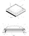
- Figs 1 and 2 show different views of a window or skylight.
- the window comprises a rectangular window portion 1 in the form of a Velux® top-hung roof window (GHL type), which is able to pivot about a horizontal axis positioned along a bottom of the skylight (to the lower right in Fig. 1 and to the right in Fig. 2 ).
- the window portion 1 is installed in a flat roof 2 and comprises a sash 3 positioned in a frame 4, which are both made up of extruded, hollow PVC profiles (in the present context flat roofs are defined as roofs having an inclination in relation to horizontal of less than about 15°).
- the frame and sash may be in the form of for example extruded aluminium profiles and they may comprise wooden parts.
- the sash 3 comprises a bottom 3a, a top 3b and two side (not shown) sash members and encloses a windowpane 5 with two layers of glazing sandwiching a layer of gas to provide insulation glazing.
- the frame 4 comprises a bottom 4a, a top 4b and two side frame members, of which only one side frame member, 4c, is shown (in Fig. 1 ).
- the bottom sash member 3a is pivotally connected to the bottom frame member 4a by means of two hinges (not shown) defining a pivot axis.
- a weather shield according to the second aspect of the invention in the form of a dome-shaped acrylic plate or dome 6 is attached to the sash 3 protecting the window portion 1. Pivoting the sash 3 and dome 6 about the pivot axis by means of a chain operator 23 embedded in the top frame member 4b provides movement between an open and a closed position of the window. The chain operator 23 may be driven automatically and may be radio controlled. Supporting the dome portion 6 are longitudinally extending sealing projections or weather strips 7, 8, sealing the sash 3 against the dome portion 6, cf. Figs 2 and 3 .
- the weather shield 6 comprises peripheral holes 9.
- a fastener 10 has been inserted through one of the peripheral holes 9, the fastener 10 being an embodiment of the fastener according to the invention. Note that in the present embodiment similar, not shown fasteners are to be inserted in the remaining holes 9 of the weather shield 6 as shown in Fig. 1 .
- Fig. 3 shows a detail of the cross-sectional view of Fig. 2 .
- the fastener 10 is shown in more detail in Figs 4 to 7 . It comprises a head part 11 connected to a connection part 12, the outer dimensions of which correspond to the inner dimensions of the holes 9.
- the connection part 12 extends into a first fastening means in the form of a clog-shaped radial protrusion 13 with an engagement member in the form of an upwards projecting tip end 14 of said clog shape.
- the head part 11 comprises grip means in the form of two finger depressions 15, 16.
- the connection part 12 comprises second fastening means in the form of two oppositely positioned snap locks 17, 18.
- the fastener 10 is integrally molded from Zytel 80633, i.e. acrylic with 33% glass.
- Figs 2 and 3 the fastener 10 is shown in a locked condition in which it fastens the weather shield 6 to the sash 3.
- the head part 11 has a lower, flat surface, which is positioned abutting an upper surface of the weather shield 6, the connection part 12 extending through a hole of the weather shield 6 into the bottom sash member 3a.
- the peripheral hole of this figure is formed in an upwardly protruding dimple 20 of the weather shield 6; the same is the case for all the peripheral holes 9.
- the tip end 14 of the radial protrusion 13 engages a corresponding engagement means of the sash 3 in the form of a downwards protruding longitudinally extending bead 19.
- the bead 19 extends in the entire circumference of the sash 3, forming a tip end of a likewise longitudinally extending part of the sash, making it somewhat resilient in an upwards direction.
- the snap locks 17, 18 When inserting the fastener into the hole the snap locks 17, 18 are positioned abutting a lower surface of the weather shield 6. Hereby, the lower surface of the head part 11 and the snap locks 17, 18 at all times cooperate to secure the fastener in the hole. To release the fastener 10 from the hole, the snap locks 17, 18 will need to be released from the inside of the weather shield 6.
- the finger depressions 15, 16 are adapted such that in the fastened position of the fastener 10 as shown in Figs. 2 and 3 rain water and snow are allowed to readily pass the head part 11.
- a soft acrylic gasket member 21 is provided between the dimple 20 and the lower surface of the head part 11 .
- This gasket member 21 is somewhat resilient, providing for a corresponding resiliency of the fastener 10, which is made use of when fastening or releasing the fastener 10 as is explained in more detail below.
- the gasket member 21 is secured, i.e. glued to the dimple 20; in other embodiments it may form part of the fastener.
- the tip end 14 is released from the bead 19 of the bottom sash member 3a by means of rotation of said fastener. Rotation can be carried out without the use of a separate tool placing a thumb and an index finger of one hand in the finger depressions 15, 16, respectively.
- the fastener 10 can be rotated either way about the connection part 12, whereby the tip end 14 passes the downwards protruding bead 19, and the fastener 10 and weather shield 6 is released from the sash 3.
- the combined resilience of the gasket member 21, longitudinal sealing members 7, 8, bead 19 and fastener itself makes it possible for the tip end 14 to pass the bead 19 with a snapping sound and sensation telling a user that the fastener 10 has been released.
- the gasket 21 and sealing members 7, 8 also ensure that the weather shield 6 is watertight in the area of the hole in the weather shield 6.
- the engagement member of the fastener and the engagement means of the sash can be provided in other forms.
- the tip ends may for example turn opposite ways compared to the embodiment in the drawings, still providing a suitable snap lock.
- a stronger fastener it may be manufactured partly or in whole from for example zinc or aluminium or other suitable materials.
- a further radial protrusion corresponding to and protruding oppositely to the radial protrusion 13 may be provided to provide for a stronger attachment. This would also prevent the fastener from tilting when being rotated to or from a locked position (see below).
- the further radial protrusion may be similar to the radial protrusion 13.
Landscapes
- Engineering & Computer Science (AREA)
- Architecture (AREA)
- Civil Engineering (AREA)
- Structural Engineering (AREA)
- General Engineering & Computer Science (AREA)
- Mechanical Engineering (AREA)
- Specific Sealing Or Ventilating Devices For Doors And Windows (AREA)
Claims (15)
- Élément de fixation (10) pour protection contre les intempéries, destiné à être guidé à travers un trou périphérique (9) d'une protection contre les intempéries (6) pour attacher cette dernière à un profilé d'organe de châssis creux d'un châssis de fenêtre (3), ledit élément de fixation (10) comprenant une partie de tête (11) connectée à une partie de connexion (12), ladite partie de tête étant prévue pour être positionnée en butée contre une surface supérieure de ladite protection contre les intempéries (6), ladite partie de connexion (12) s'étendant à travers ledit trou (9) de ladite protection contre les intempéries (6) jusque dans ledit châssis (3),
ledit élément de fixation (10) comprenant en outre un premier moyen de fixation pour verrouiller ledit élément de fixation (10) à un moyen d'engagement correspondant dudit châssis (3) lors de l'activation dudit élément de fixation (10), pour ainsi attacher ladite protection contre les intempéries (6) audit châssis (3),
ladite partie de connexion (12) s'étendant dans ledit premier moyen de fixation comprenant une saillie radiale (13) avec un organe d'engagement de manière à être verrouillée par encliquetage audit moyen d'engagement correspondant dudit châssis (3) lors de l'activation dudit élément de fixation (10), pour ainsi attacher ladite protection contre les intempéries (6) audit châssis (3),
ledit premier moyen de fixation dudit élément de fixation (10) étant prévu pour s'engager avec ledit moyen d'engagement dudit organe de châssis et être libéré de celui-ci par rotation dudit élément de fixation (10),
ladite saillie radiale (13) étant en forme de sabot, une extrémité de pointe saillant vers le haut (14) de ladite forme de sabot formant ledit organe d'engagement dudit élément de fixation (10),
caractérisé en ce
qu'un organe de garniture d'étanchéité (21) destiné à venir en butée contre ladite surface supérieure de ladite protection contre les intempéries (6) est prévu sur une surface inférieure de ladite partie de tête (11), l'élasticité de la garniture d'étanchéité (21) assurant une fixation plus facile de l'élément de fixation (10). - Élément de fixation (10) selon la revendication 1, dans lequel ledit premier moyen de fixation dudit élément de fixation est prévu pour venir en prise avec ledit moyen d'engagement dudit organe de châssis et pour être libéré de celui-ci par une rotation dudit élément de fixation (10).
- Élément de fixation (10) selon l'une quelconque des revendications précédentes, dans lequel ladite partie de tête (11) comprend des moyens de préhension pouvant être saisis à la main pour faire tourner ledit élément de fixation (10) de manière à assurer un engagement entre ledit premier moyen de fixation dudit élément de fixation (10) et ledit moyen d'engagement dudit châssis (3).
- Élément de fixation (10) selon la revendication 3, dans lequel ledit moyen de préhension comprend deux renfoncements pour les doigts (15, 16) positionnés, dans une position fixée dudit élément de fixation (10), de manière à permettre à l'eau de pluie et à la neige tombant sur ladite protection contre les intempéries (6) de passer au-delà de ladite partie de tête (11).
- Élément de fixation (10) pour protection contre les intempéries selon l'une quelconque des revendications précédentes, fabriqué en zinc ou en aluminium.
- Élément de fixation (10) selon l'une quelconque des revendications précédentes, comprenant en outre un deuxième moyen de fixation, de préférence un fermoir à cliquet (17, 18), prévu pour être positionné en butée contre une surface inférieure de ladite protection contre les intempéries (6) lorsque ladite partie de connexion (12) s'étend à travers ledit trou (9) de ladite protection contre les intempéries (6), de manière à ce qu'en coopérant avec ladite partie de tête (11), elle ne puisse pas sensiblement être libérée de ladite protection contre les intempéries (6) et qu'elle ne puisse pas tourner par rapport à cette dernière.
- Élément de fixation (10) selon l'une quelconque des revendications précédentes, ledit élément de fixation (10) étant configuré de telle sorte qu'une élasticité de l'organe de garniture d'étanchéité (21) contribue à permettre le passage de l'extrémité de pointe au-delà d'un bourrelet de la partie de fenêtre avec un bruit d'encliquetage et une sensation d'encliquetage indiquant à l'utilisateur que l'élément de fixation (10) a été libéré.
- Élément de fixation (10) selon l'une quelconque des revendications précédentes, ledit élément de fixation (10) étant configuré de telle sorte qu'une élasticité combinée de l'organe de garniture d'étanchéité (21), d'organes d'étanchéité longitudinaux et d'un bourrelet de la partie de fenêtre, et de l'élément de fixation (10) lui-même permettant à l'extrémité de pointe de passer au-delà du bourrelet avec un bruit d'encliquetage et une sensation d'encliquetage indiquant à un utilisateur que ledit élément de fixation (10) a été libéré.
- Élément de fixation (10) selon l'une quelconque des revendications précédentes, l'élément de fixation (10) étant configuré de telle sorte que l'élément de fixation (10) puisse être tourné dans n'importe quel sens autour de la partie de connexion, l'extrémité de pointe étant apte à passer au-delà d'un bourrelet saillant vers le bas du profilé d'organe de châssis de telle sorte que l'élément de fixation (10) et la protection contre les intempéries (6) soient libérés du châssis (3), une élasticité combinée de l'organe de garniture d'étanchéité (21), des organes d'étanchéité longitudinaux, du bourrelet et de l'élément de fixation (10) lui-même permettant à l'extrémité de pointe de passer au-delà du bourrelet avec un bruit d'encliquetage et une sensation d'encliquetage indiquant à un utilisateur que l'élément de fixation (10) a été libéré, et dans lequel, à partir de la position libérée, l'élément de fixation (10) est apte à être encliqueté dans sa position d'origine verrouillée de manière correspondante.
- Protection contre les intempéries (6) et partie de fenêtre (1), comprenant un élément de fixation selon l'une quelconque des revendications précédentes, ledit élément de fixation (10) étant positionné de manière à attacher un châssis (3) de la partie de fenêtre à la protection contre les intempéries (6) couvrant ledit châssis (3), ledit élément de fixation (10) s'étendant à travers un trou périphérique (9) de ladite protection contre les intempéries (6) de manière à venir en prise avec ledit châssis (3), ledit châssis (3) comprenant des organes de châssis extrudés avec un profilé d'organe de châssis creux.
- Protection contre les intempéries (6) et partie de fenêtre (1) selon la revendication 10, l'élément de fixation (10) étant selon la revendication 1, et ledit moyen d'engagement dudit organe de châssis comprenant un bourrelet saillant vers le bas (19), ladite extrémité de pointe (14) dudit organe d'engagement dudit élément de fixation (10) s'étendant vers le haut de manière à venir en prise avec ledit bourrelet saillant vers le bas (19) de manière à verrouiller par encliquetage ledit élément de fixation (10) et ledit organe de châssis l'un à l'autre par rotation dudit élément de fixation (10).
- Protection contre les intempéries (6) et partie de fenêtre (1) selon la revendication 10 ou 11, ledit trou périphérique (9) étant formé dans une boursouflure (20) saillant vers le haut de ladite protection contre les intempéries (6).
- Protection contre les intempéries (6) et partie de fenêtre (1) selon l'une quelconque des revendications 10 à 12, ledit châssis (3) sur une surface supérieure comprenant un organe d'étanchéité élastique s'étendant longitudinalement (7, 8) en butée contre une surface inférieure de ladite protection contre les intempéries (6).
- Protection contre les intempéries (6) et partie de fenêtre (1) selon l'une quelconque des revendications 10 à 13, ladite partie de fenêtre comprenant un organe de châssis supérieur (3b), un organe de châssis inférieur (3a) et deux organes de châssis latéraux (3c) définissant ledit châssis de fenêtre (3), et un organe de cadre supérieur, un organe de cadre inférieur et deux organes de cadres latéraux définissant un cadre de fenêtre (4), ledit organe de châssis inférieur (3a) étant articulé audit organe de cadre inférieur (4a) au moyen d'une articulation pivot définissant un axe de pivotement de manière à relier par pivotement ledit châssis de fenêtre (3) audit cadre de fenêtre (4).
- Protection contre les intempéries (6), destinée à être attachée à un profilé d'organe de châssis creux d'un châssis de fenêtre (3), caractérisée en ce qu'elle comprend un certain nombre d'éléments de fixation (10) selon l'une quelconque des revendications 1 à 9, des parties de tête respectives (11) desdits éléments de fixation étant positionnées en butée contre une surface supérieure de ladite protection contre les intempéries (6), des parties de connexion respectives (12) desdits éléments de fixation s'étendant à travers des trous périphériques (9) de ladite protection contre les intempéries (6).
Priority Applications (2)
| Application Number | Priority Date | Filing Date | Title |
|---|---|---|---|
| PL15189217T PL2990563T3 (pl) | 2007-12-19 | 2007-12-19 | Element złączny i osłona pogodowa |
| EP15189217.1A EP2990563B1 (fr) | 2007-12-19 | 2007-12-19 | Élément de fixation et écran de protection contre les intempéries |
Applications Claiming Priority (3)
| Application Number | Priority Date | Filing Date | Title |
|---|---|---|---|
| PCT/DK2007/050191 WO2009076951A1 (fr) | 2007-12-19 | 2007-12-19 | Pièce de fixation et bouclier de protection contre les intempéries |
| EP07846451.8A EP2242889B1 (fr) | 2007-12-19 | 2007-12-19 | Protection contre les intempéries |
| EP15189217.1A EP2990563B1 (fr) | 2007-12-19 | 2007-12-19 | Élément de fixation et écran de protection contre les intempéries |
Related Parent Applications (1)
| Application Number | Title | Priority Date | Filing Date |
|---|---|---|---|
| EP07846451.8A Division EP2242889B1 (fr) | 2007-12-19 | 2007-12-19 | Protection contre les intempéries |
Publications (2)
| Publication Number | Publication Date |
|---|---|
| EP2990563A1 EP2990563A1 (fr) | 2016-03-02 |
| EP2990563B1 true EP2990563B1 (fr) | 2019-05-08 |
Family
ID=39712742
Family Applications (2)
| Application Number | Title | Priority Date | Filing Date |
|---|---|---|---|
| EP15189217.1A Active EP2990563B1 (fr) | 2007-12-19 | 2007-12-19 | Élément de fixation et écran de protection contre les intempéries |
| EP07846451.8A Active EP2242889B1 (fr) | 2007-12-19 | 2007-12-19 | Protection contre les intempéries |
Family Applications After (1)
| Application Number | Title | Priority Date | Filing Date |
|---|---|---|---|
| EP07846451.8A Active EP2242889B1 (fr) | 2007-12-19 | 2007-12-19 | Protection contre les intempéries |
Country Status (4)
| Country | Link |
|---|---|
| EP (2) | EP2990563B1 (fr) |
| CN (1) | CN101827986B (fr) |
| PL (2) | PL2242889T3 (fr) |
| WO (1) | WO2009076951A1 (fr) |
Families Citing this family (6)
| Publication number | Priority date | Publication date | Assignee | Title |
|---|---|---|---|---|
| PL2443296T3 (pl) * | 2009-05-01 | 2016-07-29 | Vkr Holding As | Przeciwwłamaniowe urządzenie blokujące do mocowania kopułki oświetleniowej do skrzydła okiennego świetlika |
| DE102009033939B4 (de) * | 2009-07-14 | 2011-07-21 | Roto Frank Ag, 70771 | Wohndachfenster sowie Verfahren zum Befestigen eines Abdeckblechs |
| CA2849363C (fr) * | 2011-10-04 | 2016-11-08 | Vkr Holding A/S | Fenetre de toit munie d'un dispositif de fixation de recouvrement |
| CN107086440B (zh) * | 2017-06-28 | 2024-03-26 | 河南森源电气股份有限公司 | 一种转接母线组件及绝缘结构及其绝缘堵头和绝缘筒 |
| US11592197B2 (en) | 2018-09-28 | 2023-02-28 | Solatube International, Inc. | Bottom-mounted whole house fan assembly |
| GB2606199A (en) * | 2021-04-29 | 2022-11-02 | Whitesales Ltd | A roof light |
Citations (2)
| Publication number | Priority date | Publication date | Assignee | Title |
|---|---|---|---|---|
| EP0169772A1 (fr) * | 1984-07-16 | 1986-01-29 | Automobiles Peugeot | Agrafe pour l'assemblage de pièces, telles que des panneaux |
| FR2821130A1 (fr) * | 2001-02-16 | 2002-08-23 | Peugeot Citroen Automobiles Sa | Agrafe de fixation d'un element de carrosserie sur la structure d'un vehicule automobile |
Family Cites Families (20)
| Publication number | Priority date | Publication date | Assignee | Title |
|---|---|---|---|---|
| US2634146A (en) * | 1951-10-23 | 1953-04-07 | Jandor Inc | Window lock |
| CH393700A (de) * | 1960-01-02 | 1965-06-15 | Kuball Geb | Oberlicht für Gebäuderäume |
| DE1290325B (de) * | 1965-01-25 | 1969-03-06 | Esser Kg Klaus | Vorrichtung zum Befestigen einer doppelschaligen Lichtkuppel |
| NL6513475A (fr) * | 1965-10-19 | 1967-04-20 | ||
| DE7002316U (de) * | 1970-01-23 | 1970-06-25 | Esser Kg Klaus | Dachoberlicht. |
| FR2141633B1 (fr) * | 1971-06-17 | 1975-07-11 | Martin Serge | |
| NL7312441A (fr) * | 1972-12-19 | 1974-06-21 | ||
| NL7313515A (fr) * | 1973-02-15 | 1974-08-19 | ||
| DE7521548U (de) * | 1975-07-07 | 1975-11-27 | Everlite As | Oberlicht- |
| JPS6022658U (ja) * | 1983-07-22 | 1985-02-16 | 橋本フオ−ミング工業株式会社 | 車両用開閉窓のロツク装置 |
| DE9002503U1 (fr) * | 1990-03-03 | 1991-07-18 | Ramsauer, Dieter, 5620 Velbert, De | |
| CN2291459Y (zh) * | 1997-01-06 | 1998-09-16 | 汪家郴 | 叠加式复合型建筑采光罩结构装置 |
| GB2321667A (en) * | 1997-02-01 | 1998-08-05 | Willenhall Eng Ltd | Security locking device |
| US5897278A (en) * | 1998-02-05 | 1999-04-27 | Southco, Inc. | Turn fastener |
| FR2818252B1 (fr) * | 2000-12-20 | 2003-03-21 | Schneider Electric Ind Sa | Dispositif de fermeture etanche pour boitier |
| US6474921B1 (en) * | 2001-07-17 | 2002-11-05 | Trw Inc. | Two part twist fastener |
| FR2844315B1 (fr) * | 2002-09-05 | 2008-06-27 | Legrand Sa | Dispositif de fixation a quart de tour encliquetable |
| FR2850719B1 (fr) * | 2003-01-31 | 2006-12-29 | Peugeot Citroen Automobiles Sa | Agrafe de fixation d'un element de carrosserie sur une structure d'un vehicule automobile |
| JP4218506B2 (ja) * | 2003-11-19 | 2009-02-04 | 井関農機株式会社 | キャビンの窓開閉装置 |
| DE102006020697B3 (de) * | 2006-05-04 | 2007-04-26 | A. Raymond Et Cie | Drehverschluss |
-
2007
- 2007-12-19 PL PL07846451T patent/PL2242889T3/pl unknown
- 2007-12-19 PL PL15189217T patent/PL2990563T3/pl unknown
- 2007-12-19 CN CN200780101109.2A patent/CN101827986B/zh not_active Expired - Fee Related
- 2007-12-19 EP EP15189217.1A patent/EP2990563B1/fr active Active
- 2007-12-19 WO PCT/DK2007/050191 patent/WO2009076951A1/fr active Application Filing
- 2007-12-19 EP EP07846451.8A patent/EP2242889B1/fr active Active
Patent Citations (2)
| Publication number | Priority date | Publication date | Assignee | Title |
|---|---|---|---|---|
| EP0169772A1 (fr) * | 1984-07-16 | 1986-01-29 | Automobiles Peugeot | Agrafe pour l'assemblage de pièces, telles que des panneaux |
| FR2821130A1 (fr) * | 2001-02-16 | 2002-08-23 | Peugeot Citroen Automobiles Sa | Agrafe de fixation d'un element de carrosserie sur la structure d'un vehicule automobile |
Also Published As
| Publication number | Publication date |
|---|---|
| WO2009076951A1 (fr) | 2009-06-25 |
| PL2990563T3 (pl) | 2019-11-29 |
| EP2242889B1 (fr) | 2015-10-21 |
| PL2242889T3 (pl) | 2016-03-31 |
| CN101827986B (zh) | 2015-07-22 |
| EP2242889A1 (fr) | 2010-10-27 |
| CN101827986A (zh) | 2010-09-08 |
| EP2990563A1 (fr) | 2016-03-02 |
Similar Documents
| Publication | Publication Date | Title |
|---|---|---|
| EP2990563B1 (fr) | Élément de fixation et écran de protection contre les intempéries | |
| US6904725B1 (en) | Roof window with main frame and sash covering members | |
| US9151049B2 (en) | Roof window with an insulating element | |
| EP3396100B1 (fr) | Fenêtre de toit plat avec couverture extérieure | |
| US6010180A (en) | Clip-in window glazing and mounting of the window glazing in the frame of an opening | |
| US5682713A (en) | Rotatable bracket securing a window frame to a roof | |
| EP2751354B1 (fr) | Fenêtre de toit munie de recouvrement de bourrelet d'impact amélioré | |
| CA2099767A1 (fr) | Puits de lumiere | |
| US5815996A (en) | Interior-mounted cover for roof ventilator | |
| CA2849364C (fr) | Fenetre de toit munie d'un moyen de recouvrement pour cadre | |
| EP2443296B1 (fr) | Dispositif de verrouillage incrochetable pour attacher un dôme d'éclairage à un châssis de lanterneau | |
| US20080289266A1 (en) | Pivotable Gutter | |
| WO2011044906A1 (fr) | Structure de fenêtre et procédé pour monter la structure de fenêtre | |
| JPS6237866Y2 (fr) | ||
| AU2005238554B2 (en) | Pivotable gutter | |
| JPH084103A (ja) | 隙間カバー | |
| JPH0835295A (ja) | 棟飾り | |
| WO2004007864A1 (fr) | Element de noquet en tole et kit de noquets | |
| JPH04110830U (ja) | 天 窓 |
Legal Events
| Date | Code | Title | Description |
|---|---|---|---|
| PUAI | Public reference made under article 153(3) epc to a published international application that has entered the european phase |
Free format text: ORIGINAL CODE: 0009012 |
|
| AC | Divisional application: reference to earlier application |
Ref document number: 2242889 Country of ref document: EP Kind code of ref document: P |
|
| AK | Designated contracting states |
Kind code of ref document: A1 Designated state(s): AT BE BG CH CY CZ DE DK EE ES FI FR GB GR HU IE IS IT LI LT LU LV MC MT NL PL PT RO SE SI SK TR |
|
| 17P | Request for examination filed |
Effective date: 20160829 |
|
| RBV | Designated contracting states (corrected) |
Designated state(s): AT BE BG CH CY CZ DE DK EE ES FI FR GB GR HU IE IS IT LI LT LU LV MC MT NL PL PT RO SE SI SK TR |
|
| STAA | Information on the status of an ep patent application or granted ep patent |
Free format text: STATUS: EXAMINATION IS IN PROGRESS |
|
| 17Q | First examination report despatched |
Effective date: 20170309 |
|
| GRAP | Despatch of communication of intention to grant a patent |
Free format text: ORIGINAL CODE: EPIDOSNIGR1 |
|
| STAA | Information on the status of an ep patent application or granted ep patent |
Free format text: STATUS: GRANT OF PATENT IS INTENDED |
|
| INTG | Intention to grant announced |
Effective date: 20181204 |
|
| GRAS | Grant fee paid |
Free format text: ORIGINAL CODE: EPIDOSNIGR3 |
|
| GRAA | (expected) grant |
Free format text: ORIGINAL CODE: 0009210 |
|
| STAA | Information on the status of an ep patent application or granted ep patent |
Free format text: STATUS: THE PATENT HAS BEEN GRANTED |
|
| AC | Divisional application: reference to earlier application |
Ref document number: 2242889 Country of ref document: EP Kind code of ref document: P |
|
| AK | Designated contracting states |
Kind code of ref document: B1 Designated state(s): AT BE BG CH CY CZ DE DK EE ES FI FR GB GR HU IE IS IT LI LT LU LV MC MT NL PL PT RO SE SI SK TR |
|
| REG | Reference to a national code |
Ref country code: GB Ref legal event code: FG4D |
|
| REG | Reference to a national code |
Ref country code: CH Ref legal event code: EP Ref country code: AT Ref legal event code: REF Ref document number: 1130343 Country of ref document: AT Kind code of ref document: T Effective date: 20190515 |
|
| REG | Reference to a national code |
Ref country code: DE Ref legal event code: R096 Ref document number: 602007058352 Country of ref document: DE Ref country code: IE Ref legal event code: FG4D |
|
| REG | Reference to a national code |
Ref country code: NL Ref legal event code: FP |
|
| REG | Reference to a national code |
Ref country code: LT Ref legal event code: MG4D |
|
| PG25 | Lapsed in a contracting state [announced via postgrant information from national office to epo] |
Ref country code: LT Free format text: LAPSE BECAUSE OF FAILURE TO SUBMIT A TRANSLATION OF THE DESCRIPTION OR TO PAY THE FEE WITHIN THE PRESCRIBED TIME-LIMIT Effective date: 20190508 Ref country code: SE Free format text: LAPSE BECAUSE OF FAILURE TO SUBMIT A TRANSLATION OF THE DESCRIPTION OR TO PAY THE FEE WITHIN THE PRESCRIBED TIME-LIMIT Effective date: 20190508 Ref country code: FI Free format text: LAPSE BECAUSE OF FAILURE TO SUBMIT A TRANSLATION OF THE DESCRIPTION OR TO PAY THE FEE WITHIN THE PRESCRIBED TIME-LIMIT Effective date: 20190508 Ref country code: PT Free format text: LAPSE BECAUSE OF FAILURE TO SUBMIT A TRANSLATION OF THE DESCRIPTION OR TO PAY THE FEE WITHIN THE PRESCRIBED TIME-LIMIT Effective date: 20190908 Ref country code: ES Free format text: LAPSE BECAUSE OF FAILURE TO SUBMIT A TRANSLATION OF THE DESCRIPTION OR TO PAY THE FEE WITHIN THE PRESCRIBED TIME-LIMIT Effective date: 20190508 |
|
| PG25 | Lapsed in a contracting state [announced via postgrant information from national office to epo] |
Ref country code: GR Free format text: LAPSE BECAUSE OF FAILURE TO SUBMIT A TRANSLATION OF THE DESCRIPTION OR TO PAY THE FEE WITHIN THE PRESCRIBED TIME-LIMIT Effective date: 20190809 Ref country code: BG Free format text: LAPSE BECAUSE OF FAILURE TO SUBMIT A TRANSLATION OF THE DESCRIPTION OR TO PAY THE FEE WITHIN THE PRESCRIBED TIME-LIMIT Effective date: 20190808 Ref country code: LV Free format text: LAPSE BECAUSE OF FAILURE TO SUBMIT A TRANSLATION OF THE DESCRIPTION OR TO PAY THE FEE WITHIN THE PRESCRIBED TIME-LIMIT Effective date: 20190508 |
|
| REG | Reference to a national code |
Ref country code: AT Ref legal event code: MK05 Ref document number: 1130343 Country of ref document: AT Kind code of ref document: T Effective date: 20190508 |
|
| PG25 | Lapsed in a contracting state [announced via postgrant information from national office to epo] |
Ref country code: EE Free format text: LAPSE BECAUSE OF FAILURE TO SUBMIT A TRANSLATION OF THE DESCRIPTION OR TO PAY THE FEE WITHIN THE PRESCRIBED TIME-LIMIT Effective date: 20190508 Ref country code: AT Free format text: LAPSE BECAUSE OF FAILURE TO SUBMIT A TRANSLATION OF THE DESCRIPTION OR TO PAY THE FEE WITHIN THE PRESCRIBED TIME-LIMIT Effective date: 20190508 Ref country code: DK Free format text: LAPSE BECAUSE OF FAILURE TO SUBMIT A TRANSLATION OF THE DESCRIPTION OR TO PAY THE FEE WITHIN THE PRESCRIBED TIME-LIMIT Effective date: 20190508 Ref country code: RO Free format text: LAPSE BECAUSE OF FAILURE TO SUBMIT A TRANSLATION OF THE DESCRIPTION OR TO PAY THE FEE WITHIN THE PRESCRIBED TIME-LIMIT Effective date: 20190508 Ref country code: SK Free format text: LAPSE BECAUSE OF FAILURE TO SUBMIT A TRANSLATION OF THE DESCRIPTION OR TO PAY THE FEE WITHIN THE PRESCRIBED TIME-LIMIT Effective date: 20190508 |
|
| REG | Reference to a national code |
Ref country code: DE Ref legal event code: R097 Ref document number: 602007058352 Country of ref document: DE |
|
| PG25 | Lapsed in a contracting state [announced via postgrant information from national office to epo] |
Ref country code: IT Free format text: LAPSE BECAUSE OF FAILURE TO SUBMIT A TRANSLATION OF THE DESCRIPTION OR TO PAY THE FEE WITHIN THE PRESCRIBED TIME-LIMIT Effective date: 20190508 |
|
| PLBE | No opposition filed within time limit |
Free format text: ORIGINAL CODE: 0009261 |
|
| STAA | Information on the status of an ep patent application or granted ep patent |
Free format text: STATUS: NO OPPOSITION FILED WITHIN TIME LIMIT |
|
| PG25 | Lapsed in a contracting state [announced via postgrant information from national office to epo] |
Ref country code: TR Free format text: LAPSE BECAUSE OF FAILURE TO SUBMIT A TRANSLATION OF THE DESCRIPTION OR TO PAY THE FEE WITHIN THE PRESCRIBED TIME-LIMIT Effective date: 20190508 |
|
| 26N | No opposition filed |
Effective date: 20200211 |
|
| PG25 | Lapsed in a contracting state [announced via postgrant information from national office to epo] |
Ref country code: SI Free format text: LAPSE BECAUSE OF FAILURE TO SUBMIT A TRANSLATION OF THE DESCRIPTION OR TO PAY THE FEE WITHIN THE PRESCRIBED TIME-LIMIT Effective date: 20190508 |
|
| REG | Reference to a national code |
Ref country code: BE Ref legal event code: MM Effective date: 20191231 |
|
| PG25 | Lapsed in a contracting state [announced via postgrant information from national office to epo] |
Ref country code: MC Free format text: LAPSE BECAUSE OF FAILURE TO SUBMIT A TRANSLATION OF THE DESCRIPTION OR TO PAY THE FEE WITHIN THE PRESCRIBED TIME-LIMIT Effective date: 20190508 |
|
| PG25 | Lapsed in a contracting state [announced via postgrant information from national office to epo] |
Ref country code: IE Free format text: LAPSE BECAUSE OF NON-PAYMENT OF DUE FEES Effective date: 20191219 Ref country code: LU Free format text: LAPSE BECAUSE OF NON-PAYMENT OF DUE FEES Effective date: 20191219 |
|
| PG25 | Lapsed in a contracting state [announced via postgrant information from national office to epo] |
Ref country code: BE Free format text: LAPSE BECAUSE OF NON-PAYMENT OF DUE FEES Effective date: 20191231 |
|
| PGFP | Annual fee paid to national office [announced via postgrant information from national office to epo] |
Ref country code: CH Payment date: 20201215 Year of fee payment: 14 Ref country code: CZ Payment date: 20201124 Year of fee payment: 14 |
|
| PGFP | Annual fee paid to national office [announced via postgrant information from national office to epo] |
Ref country code: NL Payment date: 20201214 Year of fee payment: 14 |
|
| PG25 | Lapsed in a contracting state [announced via postgrant information from national office to epo] |
Ref country code: CY Free format text: LAPSE BECAUSE OF FAILURE TO SUBMIT A TRANSLATION OF THE DESCRIPTION OR TO PAY THE FEE WITHIN THE PRESCRIBED TIME-LIMIT Effective date: 20190508 |
|
| PG25 | Lapsed in a contracting state [announced via postgrant information from national office to epo] |
Ref country code: IS Free format text: LAPSE BECAUSE OF FAILURE TO SUBMIT A TRANSLATION OF THE DESCRIPTION OR TO PAY THE FEE WITHIN THE PRESCRIBED TIME-LIMIT Effective date: 20190908 |
|
| PG25 | Lapsed in a contracting state [announced via postgrant information from national office to epo] |
Ref country code: HU Free format text: LAPSE BECAUSE OF FAILURE TO SUBMIT A TRANSLATION OF THE DESCRIPTION OR TO PAY THE FEE WITHIN THE PRESCRIBED TIME-LIMIT; INVALID AB INITIO Effective date: 20071219 Ref country code: MT Free format text: LAPSE BECAUSE OF FAILURE TO SUBMIT A TRANSLATION OF THE DESCRIPTION OR TO PAY THE FEE WITHIN THE PRESCRIBED TIME-LIMIT Effective date: 20190508 |
|
| PG25 | Lapsed in a contracting state [announced via postgrant information from national office to epo] |
Ref country code: CZ Free format text: LAPSE BECAUSE OF NON-PAYMENT OF DUE FEES Effective date: 20211219 |
|
| REG | Reference to a national code |
Ref country code: CH Ref legal event code: PL |
|
| REG | Reference to a national code |
Ref country code: NL Ref legal event code: MM Effective date: 20220101 |
|
| PG25 | Lapsed in a contracting state [announced via postgrant information from national office to epo] |
Ref country code: NL Free format text: LAPSE BECAUSE OF NON-PAYMENT OF DUE FEES Effective date: 20220101 |
|
| PG25 | Lapsed in a contracting state [announced via postgrant information from national office to epo] |
Ref country code: LI Free format text: LAPSE BECAUSE OF NON-PAYMENT OF DUE FEES Effective date: 20211231 Ref country code: CH Free format text: LAPSE BECAUSE OF NON-PAYMENT OF DUE FEES Effective date: 20211231 |
|
| PGFP | Annual fee paid to national office [announced via postgrant information from national office to epo] |
Ref country code: GB Payment date: 20231102 Year of fee payment: 17 |
|
| PGFP | Annual fee paid to national office [announced via postgrant information from national office to epo] |
Ref country code: FR Payment date: 20231122 Year of fee payment: 17 Ref country code: DE Payment date: 20231031 Year of fee payment: 17 |
|
| PGFP | Annual fee paid to national office [announced via postgrant information from national office to epo] |
Ref country code: PL Payment date: 20231116 Year of fee payment: 17 |