EP2990563B1 - A fastener and a weather shield - Google Patents
A fastener and a weather shield Download PDFInfo
- Publication number
- EP2990563B1 EP2990563B1 EP15189217.1A EP15189217A EP2990563B1 EP 2990563 B1 EP2990563 B1 EP 2990563B1 EP 15189217 A EP15189217 A EP 15189217A EP 2990563 B1 EP2990563 B1 EP 2990563B1
- Authority
- EP
- European Patent Office
- Prior art keywords
- fastener
- sash
- weather shield
- window
- window portion
- Prior art date
- Legal status (The legal status is an assumption and is not a legal conclusion. Google has not performed a legal analysis and makes no representation as to the accuracy of the status listed.)
- Active
Links
- 239000011324 bead Substances 0.000 claims description 16
- 230000002093 peripheral effect Effects 0.000 claims description 12
- 238000007789 sealing Methods 0.000 claims description 8
- 230000004913 activation Effects 0.000 claims description 5
- XLYOFNOQVPJJNP-UHFFFAOYSA-N water Substances O XLYOFNOQVPJJNP-UHFFFAOYSA-N 0.000 claims description 5
- 230000035807 sensation Effects 0.000 claims description 4
- XAGFODPZIPBFFR-UHFFFAOYSA-N aluminium Chemical compound [Al] XAGFODPZIPBFFR-UHFFFAOYSA-N 0.000 claims description 3
- 229910052782 aluminium Inorganic materials 0.000 claims description 3
- 239000004411 aluminium Substances 0.000 claims description 3
- HCHKCACWOHOZIP-UHFFFAOYSA-N Zinc Chemical compound [Zn] HCHKCACWOHOZIP-UHFFFAOYSA-N 0.000 claims description 2
- 239000011701 zinc Substances 0.000 claims description 2
- 229910052725 zinc Inorganic materials 0.000 claims description 2
- 210000003811 finger Anatomy 0.000 description 5
- NIXOWILDQLNWCW-UHFFFAOYSA-N acrylic acid group Chemical group C(C=C)(=O)O NIXOWILDQLNWCW-UHFFFAOYSA-N 0.000 description 3
- 241001074085 Scophthalmus aquosus Species 0.000 description 1
- 239000004957 Zytel Substances 0.000 description 1
- 229920006102 Zytel® Polymers 0.000 description 1
- 238000004140 cleaning Methods 0.000 description 1
- 239000011521 glass Substances 0.000 description 1
- 238000009413 insulation Methods 0.000 description 1
- 239000000463 material Substances 0.000 description 1
- 238000000034 method Methods 0.000 description 1
- 230000008439 repair process Effects 0.000 description 1
- 210000003813 thumb Anatomy 0.000 description 1
Images

Classifications
-
- E—FIXED CONSTRUCTIONS
- E04—BUILDING
- E04D—ROOF COVERINGS; SKY-LIGHTS; GUTTERS; ROOF-WORKING TOOLS
- E04D13/00—Special arrangements or devices in connection with roof coverings; Protection against birds; Roof drainage; Sky-lights
- E04D13/03—Sky-lights; Domes; Ventilating sky-lights
- E04D13/035—Sky-lights; Domes; Ventilating sky-lights characterised by having movable parts
- E04D13/0351—Sky-lights; Domes; Ventilating sky-lights characterised by having movable parts the parts pivoting about a fixed axis
- E04D13/0352—Sky-lights; Domes; Ventilating sky-lights characterised by having movable parts the parts pivoting about a fixed axis the parts being of domed or pyramidal shape
-
- E—FIXED CONSTRUCTIONS
- E04—BUILDING
- E04D—ROOF COVERINGS; SKY-LIGHTS; GUTTERS; ROOF-WORKING TOOLS
- E04D13/00—Special arrangements or devices in connection with roof coverings; Protection against birds; Roof drainage; Sky-lights
- E04D13/03—Sky-lights; Domes; Ventilating sky-lights
- E04D13/0305—Supports or connecting means for sky-lights of flat or domed shape
- E04D13/0315—Supports or connecting means for sky-lights of flat or domed shape characterised by a curb frame
-
- E—FIXED CONSTRUCTIONS
- E04—BUILDING
- E04D—ROOF COVERINGS; SKY-LIGHTS; GUTTERS; ROOF-WORKING TOOLS
- E04D13/00—Special arrangements or devices in connection with roof coverings; Protection against birds; Roof drainage; Sky-lights
- E04D13/03—Sky-lights; Domes; Ventilating sky-lights
- E04D13/0335—Skylight guards, security devices protecting skylights or preventing objects or persons from falling through skylight openings
-
- F—MECHANICAL ENGINEERING; LIGHTING; HEATING; WEAPONS; BLASTING
- F16—ENGINEERING ELEMENTS AND UNITS; GENERAL MEASURES FOR PRODUCING AND MAINTAINING EFFECTIVE FUNCTIONING OF MACHINES OR INSTALLATIONS; THERMAL INSULATION IN GENERAL
- F16B—DEVICES FOR FASTENING OR SECURING CONSTRUCTIONAL ELEMENTS OR MACHINE PARTS TOGETHER, e.g. NAILS, BOLTS, CIRCLIPS, CLAMPS, CLIPS OR WEDGES; JOINTS OR JOINTING
- F16B21/00—Means for preventing relative axial movement of a pin, spigot, shaft or the like and a member surrounding it; Stud-and-socket releasable fastenings
- F16B21/02—Releasable fastening devices locking by rotation
-
- F—MECHANICAL ENGINEERING; LIGHTING; HEATING; WEAPONS; BLASTING
- F16—ENGINEERING ELEMENTS AND UNITS; GENERAL MEASURES FOR PRODUCING AND MAINTAINING EFFECTIVE FUNCTIONING OF MACHINES OR INSTALLATIONS; THERMAL INSULATION IN GENERAL
- F16B—DEVICES FOR FASTENING OR SECURING CONSTRUCTIONAL ELEMENTS OR MACHINE PARTS TOGETHER, e.g. NAILS, BOLTS, CIRCLIPS, CLAMPS, CLIPS OR WEDGES; JOINTS OR JOINTING
- F16B19/00—Bolts without screw-thread; Pins, including deformable elements; Rivets
- F16B19/008—Bolts without screw-thread; Pins, including deformable elements; Rivets with sealing means
Description
- The present invention relates in a first aspect to a fastener according to the introductory part of claim 1.
- To shield off a window portion positioned more or less horizontally in a flat roof it is known to position a dome-shaped weather shield above a sash of the window portion to form a skylight or roof window. The sash is embedded in a frame, which is secured to the roof, the sash and frame together forming the window portion of the window or skylight. The purpose of the weather shield is to divert water from rainfall, leaves etc. from the window by means of gravitational forces. The weather shield is typically attached to the sash by means of screws or bolts, an oblong part of each screw or bolt being guided through a peripheral hole of the weather shield. A head part of the screw or bolt abuts an upper surface of the weather shield, the oblong part extending through the hole of the weather shield to be fastened in corresponding bores of the sash.
- The weather shield is typically transported separately from the sash and mounted on the sash after the window portion has been mounted in the roof. A tool such as a suitable screwdriver corresponding to slots of the screws or bolts is necessary to fasten the screws or bolts through the holes of the weather shield and into the sash. The fastening process is thus slow and cumbersome. During repairs, cleaning or dismounting the window it is equally problematic to release the weather shield from the sash.
-
DE 10 2006 020697 B3 discloses a device for fastening light domes. -
FR 2 821 130 A1 - It is the object of the invention to provide a fastener of the type mentioned in the introduction, with which it is possible to fast, reliably and readily attach and release a weather shield to a window sash without the use of a separate tool.
- This object is met with a fastener as described in the introduction, which is characterized by the features of the characterizing part of claim 1.
- According to the invention it is thus possible to manually activate the fastener without the use of a separate tool. A simple movement by hand will engage the first fastening means of the fastener with a corresponding engagement means of the sash. It is thus made possible to attach and release a weather shield to a window sash in a fast, reliable and easy way.
- In an embodiment of the fastener according to the invention said connection part extends into said first fastening means comprising a radial protrusion with an engagement member for being snap-locked to said corresponding engagement means of said sash on activation of said fastener, thereby fastening said weather shield to said sash. In a development of this embodiment said radial projection is clog-shaped, an upwards projecting tip end of said clog shape forming said engagement member of said fastener. In a further development said first fastening means comprises a further radial protrusion corresponding to and protruding substantially oppositely to said radial protrusion for being snap-locked to corresponding engagement means of said sash. Hereby, a stronger fastening to the sash is provided, preventing the fastener from being tilted when being rotated to or from a locked position.
- In another embodiment said first fastening means of said fastener is adapted to engage and be released from said engagement means of said sash member by means of rotation of said fastener.
- In another embodiment said head part comprises grip means operable by hand to rotate said fastener such as to provide engagement between said first fastening means of said fastener and said engagement means of said sash. In a development of this embodiment said grip means comprises two finger depressions positioned such as, in a fastened position of said fastener, to allow for rain water and snow falling on said weather shield to pass said head part.
- According to the invention a gasket member for abutting said upper surface of said weather shield is provided on a lower surface of said head part. The gasket hinders intrusion of water though the hole in the weather shield. Elasticity of the gasket provides for an easier fastening of the fastener.
- In another embodiment the fastener further comprises a second fastening means, preferably a snap lock, adapted to be positioned abutting a lower surface of said weather shield when said connection part extends through said hole of said weather shield to, cooperating with said head part, be substantially unreleasable from and rotatable in relation to said weather shield. Hereby, the fastener will be able to remain secured to a weather shield even in a dismounted state of the weather shield, making it even easier to fasten the weather shield to the sash.
- In another embodiment said fastener is positioned to fasten a sash of a window portion to a weather shield covering said sash, said fastener extending through a peripheral hole of said weather shield to engage said sash, said sash comprising extruded sash members with a hollow sash member profile. If the engagement member is clog-shaped, an upwards projecting tip end of said clog shape forming said engagement member of said fastener, said engagement means of said sash member preferably comprises a downwards protruding bead, said tip end of said engagement member of said fastener extending upwards to engage said downwards protruding bead such as to snap lock said fastener and said sash member to each other on rotation of said fastener. In another development of this embodiment said peripheral hole is formed in an upwardly protruding dimple of said weather shield, which provides elasticity of the weather shield to ensure that the weather shield is not destroyed on activation of the fastener. In another development said sash on an upper surface comprises a longitudinally extending resilient sealing member abutting a lower surface of said weather shield, which similarly provides elasticity ensuring that the weather shield is not destroyed on activation of the fastener. In another development said window portion comprises a top, a bottom and two side sash members defining said window sash, and a top, a bottom and two side frame members defining a window frame, said bottom sash member being hinged to said bottom frame member by means of a pivot hinge defining a pivot axis such as to pivotally connect said window sash to said window frame.
- In a second aspect the present invention relates to a weather shield for being fastened to a hollow sash member profile of a window sash, characterized by comprising a number of fasteners according to the first aspect of the invention, respective head parts of said fasteners being positioned abutting an upper surface of said weather shield, respective connection parts of said fasteners extending through peripheral holes of said weather shield.
- The second aspect of the invention provides advantages similar to or like the advantages described above in connection with the first aspect of the invention.
- In a preferred embodiment of the weather shield according to the second aspect of the invention said respective fasteners comprise a second fastening means, preferably a snap lock, positioned abutting a lower surface of said weather shield, said fasteners, due to cooperation between said second fastening means and said head part, being substantially unreleasable from and rotatable in relation to said weather shield.
- The invention will be explained in detail in the following by means of examples of embodiments with reference to the schematic drawing, in which
-
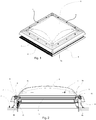
Fig. 1 is a perspective view of an embodiment of a window, -
Fig. 2 is a cross-sectional view of the window according toFig. 1 , -
Fig. 3 is a detail of the cross-sectional view ofFig. 2 , -
Fig. 4 is a perspective view of an embodiment of a fastener according to the first aspect of the present invention, -
Fig. 5 is a side view of the fastener ofFig. 4 , -
Fig. 6 is an end view of the fastener ofFig. 4 seen from the right of the fastener as shown inFig. 5 , and -
Fig. 7 is an end view of the fastener ofFig. 4 seen from the left of the fastener as shown inFig. 5 . -
Figs 1 and 2 show different views of a window or skylight. The window comprises a rectangular window portion 1 in the form of a Velux® top-hung roof window (GHL type), which is able to pivot about a horizontal axis positioned along a bottom of the skylight (to the lower right inFig. 1 and to the right inFig. 2 ). The window portion 1 is installed in aflat roof 2 and comprises a sash 3 positioned in a frame 4, which are both made up of extruded, hollow PVC profiles (in the present context flat roofs are defined as roofs having an inclination in relation to horizontal of less than about 15°). In other embodiments the frame and sash may be in the form of for example extruded aluminium profiles and they may comprise wooden parts. - The sash 3 comprises a
bottom 3a, atop 3b and two side (not shown) sash members and encloses awindowpane 5 with two layers of glazing sandwiching a layer of gas to provide insulation glazing. The frame 4 comprises abottom 4a, atop 4b and two side frame members, of which only one side frame member, 4c, is shown (inFig. 1 ). The bottomsash member 3a is pivotally connected to thebottom frame member 4a by means of two hinges (not shown) defining a pivot axis. - A weather shield according to the second aspect of the invention in the form of a dome-shaped acrylic plate or
dome 6 is attached to the sash 3 protecting the window portion 1. Pivoting the sash 3 anddome 6 about the pivot axis by means of achain operator 23 embedded in thetop frame member 4b provides movement between an open and a closed position of the window. Thechain operator 23 may be driven automatically and may be radio controlled. Supporting thedome portion 6 are longitudinally extending sealing projections orweather strips dome portion 6, cf.Figs 2 and3 . - The
weather shield 6 comprisesperipheral holes 9. InFigs 1 and 2 afastener 10 has been inserted through one of theperipheral holes 9, thefastener 10 being an embodiment of the fastener according to the invention. Note that in the present embodiment similar, not shown fasteners are to be inserted in theremaining holes 9 of theweather shield 6 as shown inFig. 1 .Fig. 3 shows a detail of the cross-sectional view ofFig. 2 . - The
fastener 10 is shown in more detail inFigs 4 to 7 . It comprises ahead part 11 connected to aconnection part 12, the outer dimensions of which correspond to the inner dimensions of theholes 9. Theconnection part 12 extends into a first fastening means in the form of a clog-shapedradial protrusion 13 with an engagement member in the form of an upwardsprojecting tip end 14 of said clog shape. Thehead part 11 comprises grip means in the form of twofinger depressions connection part 12 comprises second fastening means in the form of two oppositely positioned snap locks 17, 18. Thefastener 10 is integrally molded from Zytel 80633, i.e. acrylic with 33% glass. - In
Figs 2 and3 thefastener 10 is shown in a locked condition in which it fastens theweather shield 6 to the sash 3. Thehead part 11 has a lower, flat surface, which is positioned abutting an upper surface of theweather shield 6, theconnection part 12 extending through a hole of theweather shield 6 into thebottom sash member 3a. As is visible inFig. 3 the peripheral hole of this figure is formed in an upwardly protruding dimple 20 of theweather shield 6; the same is the case for all theperipheral holes 9. In the locked position thetip end 14 of theradial protrusion 13 engages a corresponding engagement means of the sash 3 in the form of a downwards protruding longitudinally extendingbead 19. Thebead 19 extends in the entire circumference of the sash 3, forming a tip end of a likewise longitudinally extending part of the sash, making it somewhat resilient in an upwards direction. - When inserting the fastener into the hole the snap locks 17, 18 are positioned abutting a lower surface of the
weather shield 6. Hereby, the lower surface of thehead part 11 and the snap locks 17, 18 at all times cooperate to secure the fastener in the hole. To release thefastener 10 from the hole, the snap locks 17, 18 will need to be released from the inside of theweather shield 6. - The finger depressions 15, 16 are adapted such that in the fastened position of the
fastener 10 as shown inFigs. 2 and3 rain water and snow are allowed to readily pass thehead part 11. - Between the dimple 20 and the lower surface of the head part 11 a soft
acrylic gasket member 21 is provided. Thisgasket member 21 is somewhat resilient, providing for a corresponding resiliency of thefastener 10, which is made use of when fastening or releasing thefastener 10 as is explained in more detail below. In the present embodiment thegasket member 21 is secured, i.e. glued to the dimple 20; in other embodiments it may form part of the fastener. - The
tip end 14 is released from thebead 19 of thebottom sash member 3a by means of rotation of said fastener. Rotation can be carried out without the use of a separate tool placing a thumb and an index finger of one hand in thefinger depressions fastener 10 can be rotated either way about theconnection part 12, whereby the tip end 14 passes the downwards protrudingbead 19, and thefastener 10 andweather shield 6 is released from the sash 3. The combined resilience of thegasket member 21,longitudinal sealing members bead 19 and fastener itself makes it possible for thetip end 14 to pass thebead 19 with a snapping sound and sensation telling a user that thefastener 10 has been released. - From the released position rotating the
fastener 10 to snap back to the original, locked position is done in a corresponding manner. - The
gasket 21 and sealingmembers weather shield 6 is watertight in the area of the hole in theweather shield 6. - The engagement member of the fastener and the engagement means of the sash can be provided in other forms. The tip ends may for example turn opposite ways compared to the embodiment in the drawings, still providing a suitable snap lock.
- If one wishes a stronger fastener, it may be manufactured partly or in whole from for example zinc or aluminium or other suitable materials. Also, a further radial protrusion corresponding to and protruding oppositely to the
radial protrusion 13 may be provided to provide for a stronger attachment. This would also prevent the fastener from tilting when being rotated to or from a locked position (see below). The further radial protrusion may be similar to theradial protrusion 13.
Claims (15)
- A weather shield fastener (10) to be guided through a peripheral hole (9) of a weather shield (6) for fastening the latter to a hollow sash member profile of a window sash (3), said fastener (10) comprising a head part (11) connected to a connection part (12), said head part being adapted to be positioned abutting an upper surface of said weather shield (6), said connection part (12) extending through said hole (9) of said weather shield (6) into said sash (3),
said fastener (10) further comprising a first fastening means for locking said fastener (10) to a corresponding engagement means of said sash (3) on activation of said fastener (10), thereby fastening said weather shield (6) to said sash (3),
said connection part (12) extending into said first fastening means comprising a radial protrusion (13) with an engagement member for being snap-locked to said corresponding engagement means of said sash (3) on activation of said fastener (10), thereby fastening said weather shield (6) to said sash (3),
said first fastening means of said fastener (10) is adapted to engage and be released from said engagement means of said sash member by means of rotation of said fastener (10),
wherein said radial protrusion (13) is clog-shaped, an upwards projecting tip end (14) of said clog shape forming said engagement member of said fastener (10),
characterized in that
a gasket member (21) for abutting said upper surface of said weather shield (6) is provided on a lower surface of said head part (11),
elasticity of the gasket (21) providing for an easier fastening of the fastener (10). - A fastener (10) according to claim 1, wherein said first fastening means of said fastener is adapted to engage and be released from said engagement means of said sash member by means of rotation of said fastener (10).
- A fastener (10) according to any one of the previous claims, wherein said head part (11) comprises grip means operable by hand to rotate said fastener (10) such as to provide engagement between said first fastening means of said fastener (10) and said engagement means of said sash (3).
- A fastener (10) according to claim 3, wherein said grip means comprises two finger depressions (15, 16) positioned such as, in a fastened position of said fastener (10), to allow for rain water and snow falling on said weather shield (6) to pass said head part (11).
- A weather shield fastener (10) according to any one of the previous claims, which is manufactured from zinc or aluminium.
- A fastener (10) according to any one of the previous claims, further comprising a second fastening means, preferably a snap lock (17, 18), adapted to be positioned abutting a lower surface of said weather shield (6) when said connection part (12) extends through said hole (9) of said weather shield (6) to, cooperating with said head part (11), be substantially unreleasable from and rotatable in relation to said weather shield (6).
- A fastener (10) according to any one of the previous claims, said fastener (10) being configured so that a resilience of the gasket member (21) contributes to making it possible for the tip end to pass a bead of the window portion with a snapping sound and sensation telling a user that the fastener (10) has been released.
- A fastener (10) according to any one of the previous claims, wherein said fastener (10) is configured so that a combined resilience of the gasket member (21), longitudinal sealing members and a bead of the window portion, and the fastener (10) itself make it possible for the tip end to pass the bead with a snapping sound and sensation telling a user that the fastener (10) has been released.
- A fastener (10) according to any one of the previous claims. wherein said fastener (10) is configured so that the fastener (10) can be rotated either way about the connection part, the tip end being suitable for passing a downwards protruding bead of the sash member profile so that the fastener (10) and weather shield (6) are released from the sash (3), a combined resilience of the gasket member (21), longitudinal sealing members, bead and fastener (10) itself making it possible for the tip end to pass the bead with a snapping sound and sensation telling a user that the fastener (10) has been released, and wherein, from the released position, the fastener (10) is suitable for being snapped back to the original, locked position in a corresponding manner.
- A weather shield (6) and a window portion (1), comprising a fastener according to any one of the previous claims, wherein said fastener (10) is positioned to fasten a sash (3) of the window portion to the weather shield (6) covering said sash (3), said fastener (10) extending through a peripheral hole (9) of said weather shield (6) to engage said sash (3), said sash (3) comprising extruded sash members with a hollow sash member profile.
- A weather shield (6) and a window portion (1) according to claim 10, wherein the fastener (10) is according to claim 1, and wherein said engagement means of said sash member comprises a downwards protruding bead (19), said tip end (14) of said engagement member of said fastener (10) extending upwards to engage said downwards protruding bead (19) such as to snap lock said fastener (10) and said sash member to each other on rotation of said fastener (10).
- A weather shield (6) and a window portion (1) according to claim 10 or 11, wherein said peripheral hole (9) is formed in an upwardly protruding dimple (20) of said weather shield (6).
- A weather shield (6) and a window portion (1) according to any one of claims 10 to 12, wherein said sash (3) on an upper surface comprises a longitudinally extending resilient sealing member (7, 8) abutting a lower surface of said weather shield (6).
- A weather shield (6) and a window portion (1) according to any one of claims 10 to 13, wherein said window portion comprises a top (3b), a bottom (3a) and two side (3c) sash members defining said window sash (3), and a top, a bottom and two side frame members defining a window frame (4), said bottom sash member (3a) being hinged to said bottom frame member (4a) by means of a pivot hinge defining a pivot axis such as to pivotally connect said window sash (3) to said window frame (4).
- A weather shield (6) for being fastened to a hollow sash member profile of a window sash (3), characterized by comprising a number of fasteners (10) according to any one of claims 1 to 9, respective head parts (11) of said fasteners being positioned abutting an upper surface of said weather shield (6), respective connection parts (12) of said fasteners extending through peripheral holes (9) of said weather shield (6).
Priority Applications (2)
| Application Number | Priority Date | Filing Date | Title |
|---|---|---|---|
| PL15189217T PL2990563T3 (en) | 2007-12-19 | 2007-12-19 | A fastener and a weather shield |
| EP15189217.1A EP2990563B1 (en) | 2007-12-19 | 2007-12-19 | A fastener and a weather shield |
Applications Claiming Priority (3)
| Application Number | Priority Date | Filing Date | Title |
|---|---|---|---|
| EP07846451.8A EP2242889B1 (en) | 2007-12-19 | 2007-12-19 | Weather shield |
| PCT/DK2007/050191 WO2009076951A1 (en) | 2007-12-19 | 2007-12-19 | A fastener and a weather shield |
| EP15189217.1A EP2990563B1 (en) | 2007-12-19 | 2007-12-19 | A fastener and a weather shield |
Related Parent Applications (1)
| Application Number | Title | Priority Date | Filing Date |
|---|---|---|---|
| EP07846451.8A Division EP2242889B1 (en) | 2007-12-19 | 2007-12-19 | Weather shield |
Publications (2)
| Publication Number | Publication Date |
|---|---|
| EP2990563A1 EP2990563A1 (en) | 2016-03-02 |
| EP2990563B1 true EP2990563B1 (en) | 2019-05-08 |
Family
ID=39712742
Family Applications (2)
| Application Number | Title | Priority Date | Filing Date |
|---|---|---|---|
| EP15189217.1A Active EP2990563B1 (en) | 2007-12-19 | 2007-12-19 | A fastener and a weather shield |
| EP07846451.8A Active EP2242889B1 (en) | 2007-12-19 | 2007-12-19 | Weather shield |
Family Applications After (1)
| Application Number | Title | Priority Date | Filing Date |
|---|---|---|---|
| EP07846451.8A Active EP2242889B1 (en) | 2007-12-19 | 2007-12-19 | Weather shield |
Country Status (4)
| Country | Link |
|---|---|
| EP (2) | EP2990563B1 (en) |
| CN (1) | CN101827986B (en) |
| PL (2) | PL2990563T3 (en) |
| WO (1) | WO2009076951A1 (en) |
Families Citing this family (6)
| Publication number | Priority date | Publication date | Assignee | Title |
|---|---|---|---|---|
| EP2443296B1 (en) * | 2009-05-01 | 2016-02-10 | VKR Holding A/S | A burglar-proof locking device for fastening of a light dome to a skylight window sash |
| DE102009033939B4 (en) * | 2009-07-14 | 2011-07-21 | Roto Frank Ag, 70771 | Roof window and method for fixing a cover plate |
| ES2557752T3 (en) * | 2011-10-04 | 2016-01-28 | Vkr Holding A/S | A roof window with a cover clamping device |
| CN107086440B (en) * | 2017-06-28 | 2024-03-26 | 河南森源电气股份有限公司 | Switching bus assembly, insulation structure, insulation plug and insulation cylinder thereof |
| US11592197B2 (en) | 2018-09-28 | 2023-02-28 | Solatube International, Inc. | Bottom-mounted whole house fan assembly |
| GB2606199A (en) * | 2021-04-29 | 2022-11-02 | Whitesales Ltd | A roof light |
Citations (2)
| Publication number | Priority date | Publication date | Assignee | Title |
|---|---|---|---|---|
| EP0169772A1 (en) * | 1984-07-16 | 1986-01-29 | Automobiles Peugeot | Clamp for the connection of articles, for example plates |
| FR2821130A1 (en) * | 2001-02-16 | 2002-08-23 | Peugeot Citroen Automobiles Sa | CLIP FOR FIXING A BODY ELEMENT ON THE STRUCTURE OF A MOTOR VEHICLE |
Family Cites Families (20)
| Publication number | Priority date | Publication date | Assignee | Title |
|---|---|---|---|---|
| US2634146A (en) * | 1951-10-23 | 1953-04-07 | Jandor Inc | Window lock |
| CH393700A (en) * | 1960-01-02 | 1965-06-15 | Kuball Geb | Skylight for building spaces |
| DE1290325B (en) * | 1965-01-25 | 1969-03-06 | Esser Kg Klaus | Device for fastening a double-skinned light dome |
| NL6513475A (en) * | 1965-10-19 | 1967-04-20 | ||
| DE7002316U (en) * | 1970-01-23 | 1970-06-25 | Esser Kg Klaus | ROOF LIGHT. |
| FR2141633B1 (en) * | 1971-06-17 | 1975-07-11 | Martin Serge | |
| NL7312441A (en) * | 1972-12-19 | 1974-06-21 | ||
| NL7313515A (en) * | 1973-02-15 | 1974-08-19 | ||
| DE7521548U (en) * | 1975-07-07 | 1975-11-27 | Everlite As | Skylight |
| JPS6022658U (en) * | 1983-07-22 | 1985-02-16 | 橋本フオ−ミング工業株式会社 | Vehicle opening/closing window locking device |
| DE9002503U1 (en) * | 1990-03-03 | 1991-07-18 | Ramsauer, Dieter, 5620 Velbert, De | |
| CN2291459Y (en) * | 1997-01-06 | 1998-09-16 | 汪家郴 | Laminated composite building lighting cover structure |
| GB2321667A (en) * | 1997-02-01 | 1998-08-05 | Willenhall Eng Ltd | Security locking device |
| US5897278A (en) * | 1998-02-05 | 1999-04-27 | Southco, Inc. | Turn fastener |
| FR2818252B1 (en) * | 2000-12-20 | 2003-03-21 | Schneider Electric Ind Sa | SEALED CLOSURE DEVICE FOR HOUSING |
| US6474921B1 (en) * | 2001-07-17 | 2002-11-05 | Trw Inc. | Two part twist fastener |
| FR2844315B1 (en) * | 2002-09-05 | 2008-06-27 | Legrand Sa | ENCLIQUETABLE TURN QUARTTER FIXING DEVICE |
| FR2850719B1 (en) * | 2003-01-31 | 2006-12-29 | Peugeot Citroen Automobiles Sa | FASTENING CLAMP FOR A BODY COMPONENT ON A STRUCTURE OF A MOTOR VEHICLE |
| JP4218506B2 (en) * | 2003-11-19 | 2009-02-04 | 井関農機株式会社 | Cabin window opener |
| DE102006020697B3 (en) * | 2006-05-04 | 2007-04-26 | A. Raymond Et Cie | Turning lock to join two components has fixing device with at leat two radially springing arms between two fixing sockets |
-
2007
- 2007-12-19 CN CN200780101109.2A patent/CN101827986B/en not_active Expired - Fee Related
- 2007-12-19 PL PL15189217T patent/PL2990563T3/en unknown
- 2007-12-19 EP EP15189217.1A patent/EP2990563B1/en active Active
- 2007-12-19 WO PCT/DK2007/050191 patent/WO2009076951A1/en active Application Filing
- 2007-12-19 EP EP07846451.8A patent/EP2242889B1/en active Active
- 2007-12-19 PL PL07846451T patent/PL2242889T3/en unknown
Patent Citations (2)
| Publication number | Priority date | Publication date | Assignee | Title |
|---|---|---|---|---|
| EP0169772A1 (en) * | 1984-07-16 | 1986-01-29 | Automobiles Peugeot | Clamp for the connection of articles, for example plates |
| FR2821130A1 (en) * | 2001-02-16 | 2002-08-23 | Peugeot Citroen Automobiles Sa | CLIP FOR FIXING A BODY ELEMENT ON THE STRUCTURE OF A MOTOR VEHICLE |
Also Published As
| Publication number | Publication date |
|---|---|
| PL2990563T3 (en) | 2019-11-29 |
| EP2990563A1 (en) | 2016-03-02 |
| WO2009076951A1 (en) | 2009-06-25 |
| EP2242889A1 (en) | 2010-10-27 |
| PL2242889T3 (en) | 2016-03-31 |
| EP2242889B1 (en) | 2015-10-21 |
| CN101827986B (en) | 2015-07-22 |
| CN101827986A (en) | 2010-09-08 |
Similar Documents
| Publication | Publication Date | Title |
|---|---|---|
| EP2990563B1 (en) | A fastener and a weather shield | |
| US6904725B1 (en) | Roof window with main frame and sash covering members | |
| US9151049B2 (en) | Roof window with an insulating element | |
| EP3396100B1 (en) | Flat roof window with external screen | |
| US6010180A (en) | Clip-in window glazing and mounting of the window glazing in the frame of an opening | |
| EP2751354B1 (en) | A roof window with improved striking bead covering | |
| US5815996A (en) | Interior-mounted cover for roof ventilator | |
| CA2849364C (en) | A roof window with a covering means for a frame | |
| EP2443296B1 (en) | A burglar-proof locking device for fastening of a light dome to a skylight window sash | |
| US20080289266A1 (en) | Pivotable Gutter | |
| WO2011044906A1 (en) | A window construction and a method for mounting the window construction | |
| JPS6237866Y2 (en) | ||
| AU2005238554B2 (en) | Pivotable gutter | |
| WO2004007864A1 (en) | Sheet flashing member and a flashing kit | |
| JPH04110830U (en) | sky window |
Legal Events
| Date | Code | Title | Description |
|---|---|---|---|
| PUAI | Public reference made under article 153(3) epc to a published international application that has entered the european phase |
Free format text: ORIGINAL CODE: 0009012 |
|
| AC | Divisional application: reference to earlier application |
Ref document number: 2242889 Country of ref document: EP Kind code of ref document: P |
|
| AK | Designated contracting states |
Kind code of ref document: A1 Designated state(s): AT BE BG CH CY CZ DE DK EE ES FI FR GB GR HU IE IS IT LI LT LU LV MC MT NL PL PT RO SE SI SK TR |
|
| 17P | Request for examination filed |
Effective date: 20160829 |
|
| RBV | Designated contracting states (corrected) |
Designated state(s): AT BE BG CH CY CZ DE DK EE ES FI FR GB GR HU IE IS IT LI LT LU LV MC MT NL PL PT RO SE SI SK TR |
|
| STAA | Information on the status of an ep patent application or granted ep patent |
Free format text: STATUS: EXAMINATION IS IN PROGRESS |
|
| 17Q | First examination report despatched |
Effective date: 20170309 |
|
| GRAP | Despatch of communication of intention to grant a patent |
Free format text: ORIGINAL CODE: EPIDOSNIGR1 |
|
| STAA | Information on the status of an ep patent application or granted ep patent |
Free format text: STATUS: GRANT OF PATENT IS INTENDED |
|
| INTG | Intention to grant announced |
Effective date: 20181204 |
|
| GRAS | Grant fee paid |
Free format text: ORIGINAL CODE: EPIDOSNIGR3 |
|
| GRAA | (expected) grant |
Free format text: ORIGINAL CODE: 0009210 |
|
| STAA | Information on the status of an ep patent application or granted ep patent |
Free format text: STATUS: THE PATENT HAS BEEN GRANTED |
|
| AC | Divisional application: reference to earlier application |
Ref document number: 2242889 Country of ref document: EP Kind code of ref document: P |
|
| AK | Designated contracting states |
Kind code of ref document: B1 Designated state(s): AT BE BG CH CY CZ DE DK EE ES FI FR GB GR HU IE IS IT LI LT LU LV MC MT NL PL PT RO SE SI SK TR |
|
| REG | Reference to a national code |
Ref country code: GB Ref legal event code: FG4D |
|
| REG | Reference to a national code |
Ref country code: CH Ref legal event code: EP Ref country code: AT Ref legal event code: REF Ref document number: 1130343 Country of ref document: AT Kind code of ref document: T Effective date: 20190515 |
|
| REG | Reference to a national code |
Ref country code: DE Ref legal event code: R096 Ref document number: 602007058352 Country of ref document: DE Ref country code: IE Ref legal event code: FG4D |
|
| REG | Reference to a national code |
Ref country code: NL Ref legal event code: FP |
|
| REG | Reference to a national code |
Ref country code: LT Ref legal event code: MG4D |
|
| PG25 | Lapsed in a contracting state [announced via postgrant information from national office to epo] |
Ref country code: LT Free format text: LAPSE BECAUSE OF FAILURE TO SUBMIT A TRANSLATION OF THE DESCRIPTION OR TO PAY THE FEE WITHIN THE PRESCRIBED TIME-LIMIT Effective date: 20190508 Ref country code: SE Free format text: LAPSE BECAUSE OF FAILURE TO SUBMIT A TRANSLATION OF THE DESCRIPTION OR TO PAY THE FEE WITHIN THE PRESCRIBED TIME-LIMIT Effective date: 20190508 Ref country code: FI Free format text: LAPSE BECAUSE OF FAILURE TO SUBMIT A TRANSLATION OF THE DESCRIPTION OR TO PAY THE FEE WITHIN THE PRESCRIBED TIME-LIMIT Effective date: 20190508 Ref country code: PT Free format text: LAPSE BECAUSE OF FAILURE TO SUBMIT A TRANSLATION OF THE DESCRIPTION OR TO PAY THE FEE WITHIN THE PRESCRIBED TIME-LIMIT Effective date: 20190908 Ref country code: ES Free format text: LAPSE BECAUSE OF FAILURE TO SUBMIT A TRANSLATION OF THE DESCRIPTION OR TO PAY THE FEE WITHIN THE PRESCRIBED TIME-LIMIT Effective date: 20190508 |
|
| PG25 | Lapsed in a contracting state [announced via postgrant information from national office to epo] |
Ref country code: GR Free format text: LAPSE BECAUSE OF FAILURE TO SUBMIT A TRANSLATION OF THE DESCRIPTION OR TO PAY THE FEE WITHIN THE PRESCRIBED TIME-LIMIT Effective date: 20190809 Ref country code: BG Free format text: LAPSE BECAUSE OF FAILURE TO SUBMIT A TRANSLATION OF THE DESCRIPTION OR TO PAY THE FEE WITHIN THE PRESCRIBED TIME-LIMIT Effective date: 20190808 Ref country code: LV Free format text: LAPSE BECAUSE OF FAILURE TO SUBMIT A TRANSLATION OF THE DESCRIPTION OR TO PAY THE FEE WITHIN THE PRESCRIBED TIME-LIMIT Effective date: 20190508 |
|
| REG | Reference to a national code |
Ref country code: AT Ref legal event code: MK05 Ref document number: 1130343 Country of ref document: AT Kind code of ref document: T Effective date: 20190508 |
|
| PG25 | Lapsed in a contracting state [announced via postgrant information from national office to epo] |
Ref country code: EE Free format text: LAPSE BECAUSE OF FAILURE TO SUBMIT A TRANSLATION OF THE DESCRIPTION OR TO PAY THE FEE WITHIN THE PRESCRIBED TIME-LIMIT Effective date: 20190508 Ref country code: AT Free format text: LAPSE BECAUSE OF FAILURE TO SUBMIT A TRANSLATION OF THE DESCRIPTION OR TO PAY THE FEE WITHIN THE PRESCRIBED TIME-LIMIT Effective date: 20190508 Ref country code: DK Free format text: LAPSE BECAUSE OF FAILURE TO SUBMIT A TRANSLATION OF THE DESCRIPTION OR TO PAY THE FEE WITHIN THE PRESCRIBED TIME-LIMIT Effective date: 20190508 Ref country code: RO Free format text: LAPSE BECAUSE OF FAILURE TO SUBMIT A TRANSLATION OF THE DESCRIPTION OR TO PAY THE FEE WITHIN THE PRESCRIBED TIME-LIMIT Effective date: 20190508 Ref country code: SK Free format text: LAPSE BECAUSE OF FAILURE TO SUBMIT A TRANSLATION OF THE DESCRIPTION OR TO PAY THE FEE WITHIN THE PRESCRIBED TIME-LIMIT Effective date: 20190508 |
|
| REG | Reference to a national code |
Ref country code: DE Ref legal event code: R097 Ref document number: 602007058352 Country of ref document: DE |
|
| PG25 | Lapsed in a contracting state [announced via postgrant information from national office to epo] |
Ref country code: IT Free format text: LAPSE BECAUSE OF FAILURE TO SUBMIT A TRANSLATION OF THE DESCRIPTION OR TO PAY THE FEE WITHIN THE PRESCRIBED TIME-LIMIT Effective date: 20190508 |
|
| PLBE | No opposition filed within time limit |
Free format text: ORIGINAL CODE: 0009261 |
|
| STAA | Information on the status of an ep patent application or granted ep patent |
Free format text: STATUS: NO OPPOSITION FILED WITHIN TIME LIMIT |
|
| PG25 | Lapsed in a contracting state [announced via postgrant information from national office to epo] |
Ref country code: TR Free format text: LAPSE BECAUSE OF FAILURE TO SUBMIT A TRANSLATION OF THE DESCRIPTION OR TO PAY THE FEE WITHIN THE PRESCRIBED TIME-LIMIT Effective date: 20190508 |
|
| 26N | No opposition filed |
Effective date: 20200211 |
|
| PG25 | Lapsed in a contracting state [announced via postgrant information from national office to epo] |
Ref country code: SI Free format text: LAPSE BECAUSE OF FAILURE TO SUBMIT A TRANSLATION OF THE DESCRIPTION OR TO PAY THE FEE WITHIN THE PRESCRIBED TIME-LIMIT Effective date: 20190508 |
|
| REG | Reference to a national code |
Ref country code: BE Ref legal event code: MM Effective date: 20191231 |
|
| PG25 | Lapsed in a contracting state [announced via postgrant information from national office to epo] |
Ref country code: MC Free format text: LAPSE BECAUSE OF FAILURE TO SUBMIT A TRANSLATION OF THE DESCRIPTION OR TO PAY THE FEE WITHIN THE PRESCRIBED TIME-LIMIT Effective date: 20190508 |
|
| PG25 | Lapsed in a contracting state [announced via postgrant information from national office to epo] |
Ref country code: IE Free format text: LAPSE BECAUSE OF NON-PAYMENT OF DUE FEES Effective date: 20191219 Ref country code: LU Free format text: LAPSE BECAUSE OF NON-PAYMENT OF DUE FEES Effective date: 20191219 |
|
| PG25 | Lapsed in a contracting state [announced via postgrant information from national office to epo] |
Ref country code: BE Free format text: LAPSE BECAUSE OF NON-PAYMENT OF DUE FEES Effective date: 20191231 |
|
| PGFP | Annual fee paid to national office [announced via postgrant information from national office to epo] |
Ref country code: CH Payment date: 20201215 Year of fee payment: 14 Ref country code: CZ Payment date: 20201124 Year of fee payment: 14 |
|
| PGFP | Annual fee paid to national office [announced via postgrant information from national office to epo] |
Ref country code: NL Payment date: 20201214 Year of fee payment: 14 |
|
| PG25 | Lapsed in a contracting state [announced via postgrant information from national office to epo] |
Ref country code: CY Free format text: LAPSE BECAUSE OF FAILURE TO SUBMIT A TRANSLATION OF THE DESCRIPTION OR TO PAY THE FEE WITHIN THE PRESCRIBED TIME-LIMIT Effective date: 20190508 |
|
| PG25 | Lapsed in a contracting state [announced via postgrant information from national office to epo] |
Ref country code: IS Free format text: LAPSE BECAUSE OF FAILURE TO SUBMIT A TRANSLATION OF THE DESCRIPTION OR TO PAY THE FEE WITHIN THE PRESCRIBED TIME-LIMIT Effective date: 20190908 |
|
| PG25 | Lapsed in a contracting state [announced via postgrant information from national office to epo] |
Ref country code: HU Free format text: LAPSE BECAUSE OF FAILURE TO SUBMIT A TRANSLATION OF THE DESCRIPTION OR TO PAY THE FEE WITHIN THE PRESCRIBED TIME-LIMIT; INVALID AB INITIO Effective date: 20071219 Ref country code: MT Free format text: LAPSE BECAUSE OF FAILURE TO SUBMIT A TRANSLATION OF THE DESCRIPTION OR TO PAY THE FEE WITHIN THE PRESCRIBED TIME-LIMIT Effective date: 20190508 |
|
| PG25 | Lapsed in a contracting state [announced via postgrant information from national office to epo] |
Ref country code: CZ Free format text: LAPSE BECAUSE OF NON-PAYMENT OF DUE FEES Effective date: 20211219 |
|
| REG | Reference to a national code |
Ref country code: CH Ref legal event code: PL |
|
| REG | Reference to a national code |
Ref country code: NL Ref legal event code: MM Effective date: 20220101 |
|
| PG25 | Lapsed in a contracting state [announced via postgrant information from national office to epo] |
Ref country code: NL Free format text: LAPSE BECAUSE OF NON-PAYMENT OF DUE FEES Effective date: 20220101 |
|
| PG25 | Lapsed in a contracting state [announced via postgrant information from national office to epo] |
Ref country code: LI Free format text: LAPSE BECAUSE OF NON-PAYMENT OF DUE FEES Effective date: 20211231 Ref country code: CH Free format text: LAPSE BECAUSE OF NON-PAYMENT OF DUE FEES Effective date: 20211231 |
|
| PGFP | Annual fee paid to national office [announced via postgrant information from national office to epo] |
Ref country code: GB Payment date: 20231102 Year of fee payment: 17 |
|
| PGFP | Annual fee paid to national office [announced via postgrant information from national office to epo] |
Ref country code: FR Payment date: 20231122 Year of fee payment: 17 Ref country code: DE Payment date: 20231031 Year of fee payment: 17 |
|
| PGFP | Annual fee paid to national office [announced via postgrant information from national office to epo] |
Ref country code: PL Payment date: 20231116 Year of fee payment: 17 |