EP2990296B1 - A decommissioning system for decommissioning a railway track section, as well as interface means for connecting a decommissioning system to a train safety system of the railway track - Google Patents
A decommissioning system for decommissioning a railway track section, as well as interface means for connecting a decommissioning system to a train safety system of the railway track Download PDFInfo
- Publication number
- EP2990296B1 EP2990296B1 EP15181063.7A EP15181063A EP2990296B1 EP 2990296 B1 EP2990296 B1 EP 2990296B1 EP 15181063 A EP15181063 A EP 15181063A EP 2990296 B1 EP2990296 B1 EP 2990296B1
- Authority
- EP
- European Patent Office
- Prior art keywords
- decommissioning
- train
- train safety
- section
- track
- Prior art date
- Legal status (The legal status is an assumption and is not a legal conclusion. Google has not performed a legal analysis and makes no representation as to the accuracy of the status listed.)
- Active
Links
- 238000004891 communication Methods 0.000 claims description 38
- 230000011664 signaling Effects 0.000 claims description 6
- 230000002457 bidirectional effect Effects 0.000 claims description 4
- 230000000903 blocking effect Effects 0.000 claims 1
- 210000003743 erythrocyte Anatomy 0.000 claims 1
- 238000001514 detection method Methods 0.000 description 21
- 238000012423 maintenance Methods 0.000 description 11
- 238000007726 management method Methods 0.000 description 9
- 238000004088 simulation Methods 0.000 description 7
- 230000007257 malfunction Effects 0.000 description 6
- 230000003213 activating effect Effects 0.000 description 4
- 238000009434 installation Methods 0.000 description 4
- 230000004913 activation Effects 0.000 description 3
- 238000012545 processing Methods 0.000 description 3
- CLODVDBWNVQLGO-UHFFFAOYSA-N 1,2,4,5-tetrachloro-3-(2,6-dichlorophenyl)benzene Chemical compound ClC1=CC=CC(Cl)=C1C1=C(Cl)C(Cl)=CC(Cl)=C1Cl CLODVDBWNVQLGO-UHFFFAOYSA-N 0.000 description 2
- 238000013459 approach Methods 0.000 description 2
- 238000013461 design Methods 0.000 description 2
- 238000010586 diagram Methods 0.000 description 2
- 230000000694 effects Effects 0.000 description 2
- 230000006870 function Effects 0.000 description 2
- 238000000034 method Methods 0.000 description 2
- 238000012544 monitoring process Methods 0.000 description 2
- 241001669679 Eleotris Species 0.000 description 1
- 230000004397 blinking Effects 0.000 description 1
- 239000003086 colorant Substances 0.000 description 1
- 230000001934 delay Effects 0.000 description 1
- 230000001419 dependent effect Effects 0.000 description 1
- 230000000994 depressogenic effect Effects 0.000 description 1
- 230000007935 neutral effect Effects 0.000 description 1
- 230000008092 positive effect Effects 0.000 description 1
- 239000000725 suspension Substances 0.000 description 1
Images


Classifications
-
- B—PERFORMING OPERATIONS; TRANSPORTING
- B61—RAILWAYS
- B61L—GUIDING RAILWAY TRAFFIC; ENSURING THE SAFETY OF RAILWAY TRAFFIC
- B61L23/00—Control, warning, or like safety means along the route or between vehicles or vehicle trains
- B61L23/06—Control, warning, or like safety means along the route or between vehicles or vehicle trains for warning men working on the route
Definitions
- the invention relates to a decommissioning system for decommissioning multiple sections of a railway track.
- the invention also relates to interface means for connecting a decommissioning system to a train safety system of the railway track.
- railway sections and railway yards may comprise several tracks, each track consisting of two parallel rails.
- the sections and yards are divided lengthwise into a number of so-called zones.
- Each zone comprises one or more signals for providing information and giving the engine driver of a train some form of permission.
- the zones can differ in length and can be made up of one or more sections. These railway sections are usually electrically separated from each other.
- trains are detected by a train detection system.
- a system that is frequently used, at least in the Netherlands, is the track circuit system, wherein each section comprises a power source on one side, by which an electrical potential is applied between the rails, whilst a relay is connected between the rails on the other side. This relay is energized by the power source and maintained in this active status during the time the circuit is not interrupted and the relay continues to be energized. In this quiescent condition the light of the signal for trains is green, indicating that a train is allowed to enter the zone.
- Train detection systems such as the aforesaid track circuit system, for example, can be used not only for detecting trains and providing an occupancy indication for a zone and putting the signal in the stop position on the basis thereof, but they can also be used for simulating a train so as to thus provide an occupancy indication for the zone, so that maintenance can be carried out in the zone that has been shut down.
- a warning system is known to warn track workers for approaching trains.
- a system is known to protect track worker for approaching trains by intervening on the train scheduling.
- a shunt bar or short-circuit bar/bridge
- ZKL 3000 self-signalling shunt bar
- the shunt bar simulates the presence of a train in the section of the track circuit in that the rails are shortcircuited in the same manner as would take place by the wheels and axles of a train present in the section in question.
- the relay of the track circuit system thus drops out and the signal will be put in the stop position, thereby signalling the zone to be in use, or in other words, shut down or decommissioned.
- a shunt bar which is configured to be activated by remote control (similar to the ZKL 3000 RC that is available via the present applicant) so as to thus remotely provide a zone occupancy indication.
- Such a shunt bar ensures that the zone of the railway track is decommissioned. In this way it is safe for the maintenance workers to carry out work in that zone of the railway track for as long as the shunt bar realises a short circuit, thus creating a safe zone for the rail workers.
- a drawback of such an approach is that a shunt bar must already be present in the zone or section of the railway track for every zone of the railway track that is to be decommissioned, or that it must be installed yet in said zone or section. This is a costly investment in the case of shunt bars that are already present and a labour-intensive approach in the case of shunt bars that are to be provided yet.
- An object of the invention is to provide a solution to the aforesaid drawbacks and to provide a system according to claim 1, which is in a first aspect of the invention, a decommissioning system for decommissioning multiple sections of a railway track, wherein said system is comprised of a cluster of interface means and decommissioning means, said system comprising a plurality of:
- the inventor has recognised that simulation of the presence of a train in the zone is eventually received at the train safety (supervision) level and processed into an eventually controlled occupancy indication of the zone in question.
- the simulation of the presence of a train directly on the train safety system on the one hand has the advantage that this prevents the need either to locally install a shunt bar in the track before the work is carried out or to ensure that shunt bars are already present in all zones, which leads to a significant saving in costs.
- the decommission for maintenance is thus no longer system dependent (track circuit), but that it can also be used within other train safety and management systems.
- the train safety supervision level is not the same as the train management level.
- the main difference between a train safety system and a train management system is that the train safety system is to guarantee the safety of the rail traffic and that the train management system provides the control.
- the timetable is therefore (centrally) controlled at a high level in the train management level.
- the train safety system to which the interface means according to the invention can be physically connected, is generally present in signal equipment buildings/relay cabinets (whether or not provided with actual relays or more modern PLCs or computer controlled circuits or so-called Radio Block Centres (RBCs).
- RBCs Radio Block Centres
- train safety system can also be understood to mean (part of) the Automatic Train Control (ATC), automatic train protection system, or Automatische Treinbe ⁇ nvloeding (ATB) system.
- ATC Automatic Train Control
- ATB Automatische Treinbe ⁇ nvloeding
- the system roughly consists of two elements, i.e. the track equipment and the train equipment.
- the track equipment also includes the track circuit, by means of which the presence of a train in the track section in question can be simulated, for example by means of a shunt bar as available from the present applicant. Short-circuiting the rails by means of a shunt bar will result in the track relay dropping out and the track section getting an occupancy status.
- the train safety system to which the interface means according to the invention can be physically connected, can therefore concern this part of the track equipment of the ATC, connected in a signal equipment building, RBC or Junction Box (JB) beside the track.
- the invention provides a decommissioning system which comprises interface means that can be directly connected to the train safety system.
- the location may be in a signal equipment building, RBC or JB.
- the signal equipment buildings comprise so-called B relays. These are relays having a safety function which are used in a rail safety installation (such as an NX-type installation).
- the B relays are very reliable and are guaranteed to drop out when the coil is powered off (i.e. when an axle of a train in the track section causes a short-circuit within the track circuit).
- Another feature of the B relays is that the break contacts open before the make contacts are closed.
- the interface means can therefore simulate the operation of the B relay in a similar manner.
- a decommissioning system comprises decommissioning means for decommissioning a section of the railway track by simulating the presence of a train in the track section.
- the system further comprises communication means for receiving a command to decommission the section of the railway track and to deliver status information regarding a track section that may or may not have been decommissioned.
- the communication means enable the system to remotely transmit a command to decommission a track section via an internet and/or (mobile) telephone network.
- the communication means are further capable of remotely reading the status (e.g. "track in use” or “track clear") of the track section or zone.
- the system comprises control means for controlling the decommissioning means to decommission the at least one section of the railway track on the basis of the command.
- decommissioning is understood to mean the decommissioning of the at least one section of the railway track in the broadest sense of the word.
- the rail traffic can be controlled by controlling signals and/or switches.
- a route can be set for a train.
- a route is a section of railway infrastructure that is reserved, also referred to as "scheduled", for a train.
- a train can be prevented from moving into a section by activating the appropriate signals and/or switches.
- Rails are present in all situations. Consequently, it is always possible to install a shunt bar between rails, and if the rails are operative in that zone within a track circuit system, the installation of a shunt bar is a simple and reliable manner of indicating zone to be in use.
- a decommissioning system further comprises interface means for making the decommissioning system compatible with the train safety system and enabling it to operate within said system.
- the invention also provides different manners of realising an occupancy indication, however. This is for example done by controlling one or more signals and/or switches. When a signal is activated and put in the stop position, the train safety system will detect this, and based on this detection it will not indicate the section in question to be clear. A train is not allowed to enter this section. In this way the same is realised, likewise via the train safety system, but in a different manner.
- the present invention also provides an embodiment in which a train is blocked from entering a section by inputting a command into the train safety system by which the section (or sections) in question is/are "scheduled". Rail traffic control supervises the controlling and adjusting of the timetable.
- the timetable a planning is made as to which train is present in the network at which point in time.
- those parts of the railway (section, sections or route) are reserved for that strain. This is referred to as "scheduling". If a part of the track is reserved for a train, that part is blocked to other trains. These trains cannot enter the section or sections.
- the present invention also relates to a decommissioning system wherein the decommissioning means are configured to deliver a command for the (simulated) scheduling of a train in one or more sections. This is done by communicating the scheduling of a train in that section or sections to the train safety system.
- At least the interface means and the decommissioning means are accommodated in a housing of a train safety system of the railway track.
- the decommissioning system becomes an integral part of the existing train safety system.
- the interface means are directly connected to the control unit, being relays, PLCs or computer controlled circuits so as to make direct interference in the train safety supervision level possible.
- the aforesaid means may also be accommodated in a signal equipment building of the train safety system, as the signal equipment building accommodates the train safety equipment for the respective part of the track which comprises the sections or zones that are to be decommissioned.
- signal equipment building is understood to mean a building on a railway yard in which the relay safety equipment of that railway yard is accommodated.
- At least the interface means and the decommissioning means may also be accommodated in a so-called Radio Block Centre (RBC).
- RBC Radio Block Centre
- signal equipment buildings generally comprise conventional relays
- an RBC is configured for digital processing and digitally controlling the train safety system. Accordingly, the scope of the present invention is not limited to implementation in a signal equipment building, but it also includes implementation in an RBC and equivalents thereof.
- the system comprises a cluster of a multitude of interface means and decommissioning means accommodated in various housings of train safety systems, wherein the system is configured to decommission a multitude of sections on the basis of one decommissioning command.
- the system comprises a cluster of a multitude of interface means and decommissioning means accommodated in various signal equipment buildings, wherein the system is configured to decommission a multitude of sections on the basis of one decommissioning command.
- At least the interface means and the decommissioning means may be directly accommodated in a housing of the train safety system, or be directly accommodated in a signal equipment building of a train safety system.
- Various sections together form a zone.
- Various (local) zones from the nearby track converge in a single signal equipment building, where the train safety of the various sections within the zones is controlled.
- various sections together form one zone, and various zones converge in one train safety system that is accommodated in one signal equipment building.
- a national railway system therefore comprises a multitude of said signal equipment buildings comprising train safety systems which control the safety of a multitude of local zones and of the sections that form part of said zones.
- the interface means are configured for being connected to one or more relays of the train safety system.
- the interface means may be configured to decommission a specific zone. To do so, an occupancy indication is delivered to the respective input of the relay, the PLC or other (digital) switching unit.
- the interface means may be connected to several relays, PLCs etc at the same time so as to thus control several (groups of) zones and provide an occupancy indication at the inputs in question.
- the interface means are configured for being connected to one or more PLCs of the train safety system.
- these systems may comprise relays which drop out and deliver an occupancy indication in the dropout position, but in more current train safety system they comprise PLCs or other (digital) switching units.
- the PLCs are provided with a multitude of inputs and outputs, wherein at least some of these inputs are intended for releasing a specific zone of the track or indicating it to be in use, as the case may be.
- These relays or PLCs are usually of a so-called failsafe type, which means that the standard, neutral position is a position in which the track can be safely used. In practice this means that, in the case of a relay, this relay will not release the zone of the track until the relay is energized. If the relay drops out, as a result of a train entering the zone, an occupancy indication being generated for carrying out maintenance, or a power failure, the zone will be blocked and no trains may enter the zone.
- PLCs are usually programmed accordingly.
- the interface means are configured to generate an occupancy indication to the train safety system and read back the status of an occupancy indication from the train safety system.
- the interface means may be configured as bidirectional interface means. This means that they not only deliver a control signal for an occupancy indication of a zone to the train safety system but that they also read the status thereof again. Consequently, not only control but also feedback takes place in that it is checked (by reading the status at the output) whether the train safety system has correctly carried out the command. This has a positive effect as regards the safety and reliability of the control.
- the communication means are configured to communicate the status of the occupancy indication as read to signalling means, which signalling means are configured to produce light signals at the section of the railway track that has been decommissioned.
- the communication means communicate this status to one or more users, for example within a graphic user interface on a server or, workstation or by means of a website on a computer, hand-held device, telephone or other communication means.
- the decommissioning system is connected to at least one power source of the train safety system.
- this system may be provided with its own power source, but it may also be connected to existing power sources of the train safety system. More in particular, the system may comprise an additional auxiliary power source or emergency power source, which functions as a backup for the power source of the train safety system.
- This auxiliary power source may furthermore comprise a battery to act as an uninterruptible power supply, which battery is charged by the power source of the train safety system.
- the interface means are configured to form an interface cluster together with one or more further interface means, which interface cluster can be controlled by one of a multitude of control means.
- a major advantage of the use of interface means over single relays or PLCS configured to switch single zones or sections of a track is the fact that, using the interface means, it is possible to form a cluster of interface means which are connected by the control means. If extensive work is to be carried out on a long section or a large railway yard, for example, it will be efficient if the entire area and all the sections therein can be regarded as a large, virtual zone. This zone must be given a track in use status upon commencement of the work. Without this system according to the invention, this cannot be realised within the current train safety system, and all the zones or sections must be separately controlled. This can for example be done by installing a shunt bar in every zone.
- the software of the PLCs could be adapted so as to combine them in a virtual zone.
- the PLCs need to be reprogrammed, however, in order to realise this.
- the system according to the invention does provide a possibility of composing virtual zones or clusters in a simple manner, remotely controlled via the communication means, in that use is made of the interface means. Upon commencement of the work a single command will in that case suffice for putting the signal in the stop position for a large area comprising all the selected zones configured in the command, thereby preventing trains from entering the area. Similar to the previously described embodiment, the system can provide a cluster or virtual zone which bypasses local train safety systems, i.e.
- a cluster or virtual zone may thus comprise preselected sections of, for example, zone 1 from the train safety system in the signal equipment building 1 and zones 1, 2, 3 and 4 from the train safety system in the signal equipment building 2, etc. They can be decommissioned in one go by activating one command.
- the interface means comprise one or more failsafe switches, in particular bidirectional failsafe switches, and even more in particular a double normally closed and a double normally open switch.
- the control of the train safety system by the interface means can take place, as already indicated before, by means of failsafe switches, more specifically bidirectional failsafe switches, which detect/read whether the command/control has actually been carried out.
- failsafe switches are intended for situations where the interface means are connected to a (B)-relay.
- the invention also provides a system, however, which comprises interface means which are not configured with physical mechanical failsafe switches but with digital components, which are connected to the train safety system by means of a UTP cable.
- a digital variant which is quite suitable for train safety systems comprising PLCs or an RBC, is more reliable if use is made of a safety protocol.
- control means are configured to receive a release signal via the communication means and to control the decommissioning means to decommission part of the track only upon receipt of said signal.
- the releasing of the decommissioning falls within the "give and take” principle.
- the term "give and take” is understood to mean that not only a process-oriented possibility but also a system-oriented possibility is provided in which a person responsible, such as a so-called rail traffic controller manning the post, on the one hand and a person responsible at the location of the track on the other hand, for example a contractor who is going to carry out work, can together effect a decommissioning via the system.
- a person responsible such as a so-called rail traffic controller manning the post
- a person responsible at the location of the track on the other hand for example a contractor who is going to carry out work
- the system is configured for preparing a decommission (give).
- the rail traffic controller can thus prepare a section that is to be decommissioned for maintenance.
- the rail worker (contractor or person locally responsible) can then take, i.e. activate in the system the decommissioning that has been put ready by the rail traffic controller, so that the decom
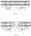
- Figure 1a shows a track which is built up of successive track sections 1 -1 - 1 - 1 +1 - etc.
- Each zone of the track may comprise one (usually several) track section 1 -1 - 1 - 1 +1 - etc.
- the track comprising the various sections is made up of rails 2a-2b, which are fixed to sleepers 3.
- the successive track sections are separated from each other by means of insulating connecting bridges 4, which are installed in one of the rails 2a-2b, or in both (as shown here).
- each track circuit of each track section is for that purpose built up of a power source 5, which is connected to each rail 2a, 2b via connections 5a, 5b, respectively.
- a dropout or rail relay 6 is provided, which is likewise electrically connected to the two rails 2a, 2b of the section in question via connections 6a, 6b, respectively.
- Figure 1b shows the situation in which a train 7 enters the track section 10 from the left, seen in the figure.
- the axles 7a of the train cause a short-circuit between the two rails 2a-2b, as a result of which current flows from the power source 5 via the connection 5a, the rail 2a, the axles 7a and back to the power source 5 via the other rail 2b and the connection 5b.
- This situation is shown in figure 1b .
- the track signals of the section comprising the track section 10 in question will be put in the stop position. Putting the signals in the stop position means that the zone in question is protected and
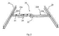
- Figure 2 shows a prior art shunt bar, which is provided with means 24 for activating and de-activating the shunt bar by remote control.
- the short-circuit 20 consists of two arm members which are hinged together by means of a hinge 22.
- the hinge makes it possible to install the bar between two rails 2a-2b, for example by exerting some pressure on the upper side of the bar using a foot. Following this, the bar will be securely clamped between the rails.
- the bar 20 comprises two contact parts 23a-23b, by means of which the bar is brought into electrical contact with the respective rails 2a-2b.
- the two arms of the bar are not continuously in electrical contact with each other, however, but they can be connected and disconnected by means of a control element present on the bar or by remote control from a communication module.
- the shunt bar Upon being connected, the shunt bar will bring the first rail 2a into electrical contact with the second rail 2b. As a result, the track zone in question will be decommissioned by indicating it to be in use and putting the signal in the stop position.
- the bar further comprises a monitoring module 25 for monitoring the short-circuit resistance between the two rails.
- the shunt bar shown in figure 2 is configured as a portable shunt bar. This means that it can be removed and be reused elsewhere for decommissioning a track zone at that location. In another embodiment, it may also form an integral part of a sleeper of the track and thus be permanently incorporated in the section. In yet another embodiment, it may also be accommodated near the track, for example in a junction box that is already present beside the track.
- the shunt bar 20 can communicate with a central processing unit using a communication module 24, and for example transmit the short-circuiting status to a control centre. Via the central processing unit, the communication module can also receive a command to activate and de-activate the shunt bar by remote control.
- the above description relates to a train detection system that is based on a track circuit system. Not all the tracks in the Netherlands, and certainly outside the Netherlands, make use of this system, however.
- the detection of trains in such other systems takes place by counting the number of axles, using an axle counter, at the beginning of a section or zone. If the number of detected axles at the beginning of the section equals the number of axles at the end of the section, it can be concluded that the train has left the section. In that case it can be determined that no train is present in the section and that the occupancy indication for that section no longer applies. Other trains can then enter the section again.
- axle counters also other detection systems are used, such as detection loops, pedals that are depressed when the train passes thereover, etc. The skilled person will appreciate what other systems are known and can be used.
- trains can also be detected on the basis of a GSM connection, for example by means of a GSM-R(rail) connection specially specified for trains.
- GSM-R(rail) connection specially specified for trains.
- newer mobile network standards such as 3G, 4G or specific train standards such as Future Railway Mobile Radio System, FRMRS.
- Figure 3 shows an embodiment of the invention of a decommissioning system that does not exhibit the above drawbacks.
- FIG 3 is a general view of several decommissioning systems 10, 10', 10" according to an embodiment of the invention.
- Two side-by-side track sections 1, 1' each comprising rails 2a, 2b (2a', 2b' and 2a", 2b") and a train signal 20 (20', 20"), for each local signal equipment building 101, 101', 101" are shown by way of illustration.
- the track section 1 (1', 1") is monitored for the presence of a train by means of a track circuit system (not shown), axle counter, GSM-R detection or other form of train detection. This detection can be transmitted, via cables 15a, 15b (15a', 15b' and 15a", 15b", respectively), to a train safety building such as a signal equipment building 101 (101', 101").
- interface means 15 (15', 15") are provided in this building, thus forming part of the train safety system, and by way of practical example in the signal equipment building, which interface means are directly physically connected to the train detection part of the train safety system.
- a decommissioning system according to the invention directly interferes with the train safety means (in the signal equipment buildings) rather than with the physical track, i.e. the rails.
- the interface means 15 (15', 15") are centrally provided directly near the train safety means in the signal equipment building 101 (101', 101 "), the risk of damage is reduced, among other things. After all, in comparison with a shunt bar installed in the track, a system that is installed in a signal equipment building is not exposed to extreme weather conditions (extreme cold, snow, ice, frost, rain, hail, extreme heat, etc) and is better protected against theft and vandalism. This has a positive respect as on the reliability and the safety of the system.
- a project for work on the track also called a working zone, may comprise one or more zones.
- Each zone comprises one or more clusters and each cluster comprises one or more sections. Sections are thus the smallest in size, followed by clusters and finally zones.
- the invention relates to the generation of an occupancy indication for at least one section, using the interface means. Within the scope of the present invention, at least one section is concerned, therefore.
- This project is also called a site safety instruction (SSI) of a clear track, zone or single section.
- SSI site safety instruction
- the design is made, verified and validated (for example at the office 100 via central server 150), and subsequently one SSP (site safety person) or a group of SSPs 150 can release the project via a local computer, tablet computer etc that is connected to the central server 150.
- the released project is then displayed to the COSS (controller of site safety) employee 150c, who may be on site.
- the COSS controller of site safety employee 150c
- the COSS controller of site safety employee 150c
- the SSP determines what, when, where, using what means, and how switching will take place by the COSS 150c.
- a green LED on the interface means 15 (15', 15" will blink.
- the decommissioning is cancelled by deactivating the project, which can be done by the COSS.
- the product can be given back and taken back so as to prevent the project still being displayed to a COSS 150c on duty.
- a product could thus be conceived at the office 100 and be verified and validated at said office, and a command to activate an occupancy indication on the train safety systems of only the signal equipment buildings 101 and 101" could be generated, so that the signals 20 and 20" for the sections associated with the rails 2a, 2b and 2a", 2b" will be put in the stop position and an occupancy indication will be activated.
- This command is made available to the COSS 150c via the central server.
- the COSS 150c is the person who is locally responsible for safety and who activates the decommissioning prior to the commencement of the work by logging into the server 150 (by personal authentication).
- the command is ready and is communicated to the decommissioning means and the interface means 15, 15" in the signal equipment buildings 101 and 101" via the communication means.
- the local decommissioning means interfere with the train safety system via the interface means 15, 15" for decommissioning the sections of the rails 2a, 2b and 2a", 2b".
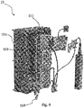
- the interface means 15 are shown in more detail in figure 4 .
- the control means 15 are preferably accommodated in an explosion-proof housing 151 and built up around a PCB 152, on which the necessary components are mounted.
- the housing with the interface means that is shown in figure 4 is to be interpreted solely as an example, however. Other variants thereto are also conceivable, which variants fall within the inventive concept and the scope of the appended claims.
- the variant shown in figure 4 is configured to be connected to a (B)-relay and concerns a single circuit.
- the interface means 15 can be many times more compact. Another advantage of electronic, not relay-based interface means is that multiple switching is possible therewith.
- the control means 15 are preferably supplied with power from a power source that forms part of the infrastructure 100-101 of the train safety system. In this way a reliable operation of the system is ensured, so that the safety of the rail workers in the case of a decommissioning is guaranteed.
- an auxiliary power source 153 is mounted on the PCB 152, so that the system need not be decommissioned but will continue to be operational in case of a malfunction in the train safety system and an undesirable failure of the main power source. This further contributes to safer working conditions for rail workers in and beside the track section 2-2' in question.
- the auxiliary power source 153 in particular comprises one or more batteries, which can be recharged by the main power source that forms part of the infrastructure 101-101 of the train safety system. In this way the functionality of the system according to the invention is at all times ensured, even in case of unexpected malfunctions.
- the decommissioning system 15 comprises decommissioning means, which generate an occupancy indication.
- the system further comprises communication means via which the system communicates with an interface or other form of communication over a network. This communication is shown in figure 3 and takes place between the central (web) server 150 and all the persons and apparatuses that can be connected thereto, such as the user 150c or a remote user 150a who can log into the server and read the status of the occupancy indication but also input an occupancy indication command.
- the user 150c can for example locally activate the occupancy indication command.
- the server 150 is further connected to the interface means 15, 15', 15" in the local signal equipment buildings 101, 101', 101" via the communication channels 17, 17', 17".
- the system further comprises control means which are configured to control the decommissioning means and to convert instructions received via the communication means into commands, so that the decommissioning means can be controlled on the basis thereof.
- the system 15 is configured to decommission a section or an entire zone of a track in a controlled manner by generating an occupancy indication.
- a shunt bar is placed between the rails
- the decommissioning means are placed inside a signal equipment building and consequently outside the risk area of the track.
- the interface means Via the interface means the system is hardwired to the train safety system in the signal equipment building and the switch, i.e. the decommissioning means, is remotely controlled by the control means, i.e. via the communication means, to effect the decommissioning and read whether it meets the requirements made thereof.
- the result is made available again, for example to the person responsible for the safety, via the communication means. All these means are locally housed in the signal equipment building 101, 101', 101", and linked together via the web server 150.
- Figure 5 is a block diagram showing the principle of operation of the system 15 according to one embodiment of the invention, which is specifically configured for being connected to a train safety system which comprises relays and which is switched (off) on the basis of said relays.
- the invention also provides a digital/electronic variant which is configured for being connected to a train safety system which does not comprise relays but which comprises PLCs or other computer-controlled/switched protection circuits, as is the case in an RBC.
- the interface means do not comprise conventional switches 211 and (failsafe) relays 213, but they are configured as digital means and control one or more sections simultaneously, for example via a computer interface over a UTP cable or the like.
- the invention also provides interface means that can be connected to a train safety system that comprises both PLCs and relays, however, for example a system in which the PLCs (digital/electronic) are controlled by the interface means and the PLCs subsequently control the relays.
- One or more components 210, 212, 214 may be configured as redundant components with a view to increasing the reliability and availability.
- Various components can be distinguished in the block diagram. Centrally arranged is the MCU, being a central processor (or several processors) 201, also called the control means, which controls and checks the entire system.
- the control means and the rest of the system are supplied with energy by the PSU 202.
- Said PSU is in turn supplied with power from a 12 V rail of the signal box or signal equipment building, for example, which is already present in the safety system.
- Watchdog 203 monitors the systems and checks whether the system still reacts. If it does not, the supply of power is briefly stopped, causing the system to restart.
- Logging 204 takes place internally for writing all events to an SD card, for example, or to another form of local storage.
- Indication 205 provides an indication whether the site is safe. It may to that end comprise an LED, which can blink green if the site is safe. A condition is that this includes not only detection whether the site is safe but also whether the system is functioning properly. Only in that case will a status report in the form of a blinking green LED be provided. As the skilled person will appreciate, these status reports may also be provided using different LEDs, colours or other signalling forms.
- switching to an occupancy indication can also take place manually by the manual 206 element. It may be provided with a key (see figure 4 , numeral 154), so that local switching of the occupancy indication can only take place if the correct key is used.
- the MCU 201 communicates with external means via a communication channel or via communication means 207 on the basis of a reliable protocol, such as the CP3000 protocol.
- a reliable protocol such as the CP3000 protocol.
- Other apparatuses available via the present applicant, such as an MTinfo, can co-operate with this system on the basis of such a protocol.
- Detection 208 detects whether the system is in the correct position, and control 209 controls the switch and it also checks whether the switch is indeed able to switch, which is done prior to the actual switching thereof.
- Drive 210 is used for driving the switch to switch individual segments to the correct position, and measure 212 is used for measuring whether the individual switching segments of the switch have been switched to the correct position. The result of this is transmitted to control block 209.
- Switch 211 carries out the actual activation. These can be remotely operated via the communication means, CP3000 and MCU, and in particular comprise a double redundant, bi-directional failsafe switch.
- the interface module is indicated at 213, it forms the interface between the rest of the system and in particular the decommissioning means in the form of the switch 211 on the one side and the interface with the train protection system in the signal equipment building on the other side.
- Feedback 214 combines the feedback from the signal equipment building with the internal feedback from the system and translates this into a detection status.
- the detection status may either be "safe” or “unsafe” (for the rail worker).
- the interface 214 to the signal box consists of a 2x normally open and 2x normally closed connection and the feedback connection.
- the communication means 207 make a connection with the web server 150 of figure 3 via a GPRS or Ethernet module 16 and make the information available to the users in question via said channel.
- GPRS and Ethernet are mentioned purely by way of illustration. The skilled person will appreciate that these terms refer to a wireless and a hardwired connection, respectively. Within that framework, the term GPRS is understood to include current standards but also new/future standards such as 3G and 4G.
- Ethernet is understood to mean a fixed connection that may already be present in the signal equipment building.
- the system may furthermore be provided with a GPS module 217, by means of which the system can be located and which is also suitable for synchronising the internal clock of the system.
- the communication means communicate (wirelessly or via a fixed connection) with the coordinating web-based management system 219, which is available as the MTinfo system from the present applicant. Via this system users can control the system via a web interface 220, and all the data in the system is safely written to a database 219. Using a remote control device, the system can be used at any location via remote 221 for decommissioning one (or several) zone(s) or section(s).
- the switch 211 may be configured as a so-called bi-directional failsafe switch.
- the switch is provided with a memory module, in which the actual operating status of the train simulation unit can be stored.
- the failsafe status of the bi-directional switch is that status which maintains safety in the track section in question.
- the train simulation unit is in functional operation and consequently simulates the presence of a train in a track section allocated to the system (and thus provides an occupancy indication to further trains) and the system gets out of operation due to a malfunction
- the bi-directional failsafe switch will maintain the "occupancy indication" rather than switch off automatically. In this way the safety of the rail workers in the track section in question is guaranteed, so that the last status will be maintained also in the case of a malfunction in the train simulation unit.
- the "non-functional operation" status is the failsafe status of the bi-directional switch, in which status the availability of the train protection system is maintained.
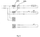
- the bi-directional switch is provided with two switch contacts 300a-300b.
- Contact 300a is a contact which is closed when the system, in particular the decommissioning means thereof, is not "on”.
- the switch contact 300b is open in that situation.
- the switch contact 300a will be open and the switch contact 300b will be closed.
- the system continuously monitors the status of the protection means (made up of the two switch contacts 300a-300b) and the system will not provide a "safe" indication until a closed contact has been detected.
- the communication interface is configured so that a situation in which both contacts are closed upon switching of the switch contacts 300a-300b cannot occur.
- the bi-directional switch is made up of a circuit with 2 Normally Closed and 2 Normally Open terminals. This provides an effective interface connection with all kinds of different types of train protection systems as indicated before and used in various countries.
- the status of the bi-directional switch is remotely monitored via the communication means, whilst also the status of the train protection system is continuously monitored. Periodically (for example every 0.5 seconds locally and every 3 seconds remotely via the communication means/network) the status of the switch is translated into a status for the user, which status may be "functional operation” or "non-functional operation”.
Description
- The invention relates to a decommissioning system for decommissioning multiple sections of a railway track.
- The invention also relates to interface means for connecting a decommissioning system to a train safety system of the railway track.
- Not only the Dutch railway network but also railway networks in other countries comprise a good deal of multi-track sections and railway yards. These sections and yards may comprise one track, but generally they comprise several tracks. If more tracks are used, also referred to as multitracks, trains travelling in opposite directions have their own track, for example when a double track is available, this in contrast to a single track, where trains must use one and the same track for both directions.
- Besides single track and double track sections and railway yards there are also sections and railway yards where three, or in some cases even four, tracks run parallel to each other and at least in the Netherlands there are a few instances of six-track railway sections.
- As indicated, railway sections and railway yards may comprise several tracks, each track consisting of two parallel rails. The sections and yards are divided lengthwise into a number of so-called zones. Each zone comprises one or more signals for providing information and giving the engine driver of a train some form of permission. The zones can differ in length and can be made up of one or more sections. These railway sections are usually electrically separated from each other.
- Within the sections, trains are detected by a train detection system. A system that is frequently used, at least in the Netherlands, is the track circuit system, wherein each section comprises a power source on one side, by which an electrical potential is applied between the rails, whilst a relay is connected between the rails on the other side. This relay is energized by the power source and maintained in this active status during the time the circuit is not interrupted and the relay continues to be energized. In this quiescent condition the light of the signal for trains is green, indicating that a train is allowed to enter the zone.
- When a train enters the track section, it causes a short circuit between the two rails via its axles and wheels. As a result of this short circuit, the relay is no longer energized, causing it to drop out. As a result of said dropping out of the track relay, the track signal will be put in the stop position, indicating that this zone of the railway track selection ahead of them is in use, a so-called "occupancy indication", or "track in use" or "track possession". As long as the signal is in the stop position for the zone in question, indicating it to be in use, other trains will not be allowed to enter the zone.
- In addition to the aforesaid track circuit train detection, also other train detection systems are known wherein the axles of a train are counted using a sensor so as to thus determine whether a train is entering the zone, on the basis of which determination an occupancy indication is provided and the signals are put in the stop position.
- The railway network is being used increasingly intensively and must meet increasingly stringent requirements. Regular maintenance is required, therefore. In order to be able to carry out this maintenance in a safe manner, parts of a section are shut down, i.e. decommissioned. Train detection systems, such as the aforesaid track circuit system, for example, can be used not only for detecting trains and providing an occupancy indication for a zone and putting the signal in the stop position on the basis thereof, but they can also be used for simulating a train so as to thus provide an occupancy indication for the zone, so that maintenance can be carried out in the zone that has been shut down.
- From
EP1308366 A1 a warning system is known to warn track workers for approaching trains. FromEP 1674370 A1 a system is known to protect track worker for approaching trains by intervening on the train scheduling. - It is known to use a shunt bar, or short-circuit bar/bridge, for creating a short circuit between two rails of the zone that is to be shut down for maintenance, i.e. decommissioned. Thus a self-signalling shunt bar (ZKL 3000) as described in
NL 1033077 - From
NL 1033581 - With such a shunt bar it is possible to activate and de-activate the shunt by remote control. The bar can thus remain in the section; when work is to be carried out the decommissioning of a section can be realised by remote control. The advantage of this is not only that central control thus becomes possible; the time that is otherwise needed for installing the shunt bar and realising the decommissioning on site is thus no longer lost.
- Such a shunt bar ensures that the zone of the railway track is decommissioned. In this way it is safe for the maintenance workers to carry out work in that zone of the railway track for as long as the shunt bar realises a short circuit, thus creating a safe zone for the rail workers.
- A drawback of such an approach is that a shunt bar must already be present in the zone or section of the railway track for every zone of the railway track that is to be decommissioned, or that it must be installed yet in said zone or section. This is a costly investment in the case of shunt bars that are already present and a labour-intensive approach in the case of shunt bars that are to be provided yet.
- Another drawback is that the known solutions only suffice for realising an occupancy indication if a track circuit system is used. In the future and in other countries work will be carried out in zones that are protected by other systems. An example of this is the increasingly important European Rail Traffic Management System (ERTMS). The installation of a shunt bar between the rails of an ERTMS-protected railway track does not guarantee that an occupancy indication will be generated and maintenance work can be carried out in a safe manner. In many cases it concerns the control of switches and signals to close off a track section to trains so as to thus create a safe place to work.
- Yet another drawback is that the known solutions are only capable of locally realising an occupancy indication by installing one or more shunt bars. Current systems are inadequate for realising an occupancy indication over a multitude of local, different train management systems in a simple manner and realising a large zone comprising several sections.
- An object of the invention is to provide a solution to the aforesaid drawbacks and to provide a system according to
claim 1, which is in a first aspect of the invention, a decommissioning system for decommissioning multiple sections of a railway track, wherein said system is comprised of a cluster of interface means and decommissioning means, said system comprising a plurality of: - decommissioning means configured to decommission at least one section of the railway track and close it off to trains by generating an occupancy indication;
- communication means configured to receive a command to decommission the section of the railway track and to deliver status information regarding a section of the railway track that has or has not been decommissioned;
- control means configured to control the decommissioning means to decommission the section of the railway track on the basis of said command;
- interface means which can be physically connected to a train safety system of the railway track on the one hand and to the decommissioning means on the other hand and which are configured to activate the decommissioning of the track section within the train safety level by generating an occupancy indication to the train safety system;
- wherein at least each interface means and decommissioning means are accommodated in different housings of a train safety system, or accommodated in different signal equipment buildings of said train safety system, such that each housing or signal equipment building is provided with an interface means and associated decommissioning means, for said system to decommission said multiple sections associated with different housings of train safety systems or different signal equipment building, and for each of said interface means and decommissioning means to decommission a respective section of said multiple sections on the basis of a single decommissioning command.
- When work is to be carried out on the railway track, the part of the railway track in question, one or more sections which together form a zone, need to be blocked such that there is a guarantee that trains cannot enter said zone. This can be realised by locally installing a shunt bar in a section of the zone, by means of which the presence of a train in said zone is simulated.
- The inventor has recognised that simulation of the presence of a train in the zone is eventually received at the train safety (supervision) level and processed into an eventually controlled occupancy indication of the zone in question. The simulation of the presence of a train directly on the train safety system on the one hand has the advantage that this prevents the need either to locally install a shunt bar in the track before the work is carried out or to ensure that shunt bars are already present in all zones, which leads to a significant saving in costs. On the other hand it is an advantage that the decommission for maintenance is thus no longer system dependent (track circuit), but that it can also be used within other train safety and management systems.
- The train safety supervision level is not the same as the train management level. The main difference between a train safety system and a train management system is that the train safety system is to guarantee the safety of the rail traffic and that the train management system provides the control. The timetable is therefore (centrally) controlled at a high level in the train management level. The (electrical and mechanical) protection, as realised by means of switches and/or signals, therefore (locally) takes place at a low level, being the train safety supervision level. These differences between train management and train safety can therefore not only be indicated in abstract levels, but they are usually also present at physically different locations in the railway system. Consequently, the train safety system, to which the interface means according to the invention can be physically connected, is generally present in signal equipment buildings/relay cabinets (whether or not provided with actual relays or more modern PLCs or computer controlled circuits or so-called Radio Block Centres (RBCs).
- The term "train safety system" can also be understood to mean (part of) the Automatic Train Control (ATC), automatic train protection system, or Automatische Treinbeïnvloeding (ATB) system. This system makes it possible to prevent accidents, for example resulting from the engine driver's missing a red signal. The system roughly consists of two elements, i.e. the track equipment and the train equipment. The track equipment also includes the track circuit, by means of which the presence of a train in the track section in question can be simulated, for example by means of a shunt bar as available from the present applicant. Short-circuiting the rails by means of a shunt bar will result in the track relay dropping out and the track section getting an occupancy status. According to the invention, the train safety system, to which the interface means according to the invention can be physically connected, can therefore concern this part of the track equipment of the ATC, connected in a signal equipment building, RBC or Junction Box (JB) beside the track.
- As described, the invention provides a decommissioning system which comprises interface means that can be directly connected to the train safety system. The location may be in a signal equipment building, RBC or JB. Traditionally, the signal equipment buildings comprise so-called B relays. These are relays having a safety function which are used in a rail safety installation (such as an NX-type installation). The B relays are very reliable and are guaranteed to drop out when the coil is powered off (i.e. when an axle of a train in the track section causes a short-circuit within the track circuit). Another feature of the B relays is that the break contacts open before the make contacts are closed. According to the invention the interface means can therefore simulate the operation of the B relay in a similar manner. Currently, many of the conventional B relays have been exchanged for electrical (computer and/or PLC) rail safety systems; examples of this include Siemens' SIMIS system, Alstom's VPI's Smartlock and Bombardier's EBILOCK. The interface means according to the invention can also be connected to these electrical rail safety systems, however.
- In a first aspect, a decommissioning system according to the invention comprises decommissioning means for decommissioning a section of the railway track by simulating the presence of a train in the track section. The system further comprises communication means for receiving a command to decommission the section of the railway track and to deliver status information regarding a track section that may or may not have been decommissioned. The communication means enable the system to remotely transmit a command to decommission a track section via an internet and/or (mobile) telephone network. The communication means are further capable of remotely reading the status (e.g. "track in use" or "track clear") of the track section or zone. In addition to that, the system comprises control means for controlling the decommissioning means to decommission the at least one section of the railway track on the basis of the command. The term " decommissioning" is understood to mean the decommissioning of the at least one section of the railway track in the broadest sense of the word. Thus the rail traffic can be controlled by controlling signals and/or switches. In this way a route can be set for a train. A route is a section of railway infrastructure that is reserved, also referred to as "scheduled", for a train. Thus a train can be prevented from moving into a section by activating the appropriate signals and/or switches. On the other hand it is also possible to simulate the presence of a train by means of a train detection system. Simulating the presence of a train achieves the same object of shutting down or decommissioning the at least one section to rail traffic.
- Rails are present in all situations. Consequently, it is always possible to install a shunt bar between rails, and if the rails are operative in that zone within a track circuit system, the installation of a shunt bar is a simple and reliable manner of indicating zone to be in use.
- In order to be able to interfere directly in the train safety system, a decommissioning system according to the invention further comprises interface means for making the decommissioning system compatible with the train safety system and enabling it to operate within said system.
- Whereas in the prior art a short-circuit is generated, thereby simulating the presence of a train, by installing a shunt bar, in the present invention the presence of a train is simulated by activating a signal at, for example, a train detection input of the train safety system.
- In the present application the short-circuiting of the rails of a section is described purely by way of example. Eventually this will result, via the train detection system (in particular the track circuit system) in a section that is indicated to be "in use".
- The invention also provides different manners of realising an occupancy indication, however. This is for example done by controlling one or more signals and/or switches. When a signal is activated and put in the stop position, the train safety system will detect this, and based on this detection it will not indicate the section in question to be clear. A train is not allowed to enter this section. In this way the same is realised, likewise via the train safety system, but in a different manner. The present invention also provides an embodiment in which a train is blocked from entering a section by inputting a command into the train safety system by which the section (or sections) in question is/are "scheduled". Rail traffic control supervises the controlling and adjusting of the timetable. In accordance with a particular plan, the timetable, a planning is made as to which train is present in the network at which point in time. In accordance with this planning, those parts of the railway (section, sections or route) are reserved for that strain. This is referred to as "scheduling". If a part of the track is reserved for a train, that part is blocked to other trains. These trains cannot enter the section or sections. The present invention also relates to a decommissioning system wherein the decommissioning means are configured to deliver a command for the (simulated) scheduling of a train in one or more sections. This is done by communicating the scheduling of a train in that section or sections to the train safety system.
- In the claimed embodiment, at least the interface means and the decommissioning means are accommodated in a housing of a train safety system of the railway track.
- By accommodating at least the interface means and the decommissioning means in a housing of a train safety system in such a practical embodiment, the decommissioning system becomes an integral part of the existing train safety system. The interface means are directly connected to the control unit, being relays, PLCs or computer controlled circuits so as to make direct interference in the train safety supervision level possible. In the claimed embodiment, the aforesaid means may also be accommodated in a signal equipment building of the train safety system, as the signal equipment building accommodates the train safety equipment for the respective part of the track which comprises the sections or zones that are to be decommissioned. The term "signal equipment building" is understood to mean a building on a railway yard in which the relay safety equipment of that railway yard is accommodated. According to one embodiment of the invention, however, at least the interface means and the decommissioning means may also be accommodated in a so-called Radio Block Centre (RBC). Whereas signal equipment buildings generally comprise conventional relays, an RBC is configured for digital processing and digitally controlling the train safety system. Accordingly, the scope of the present invention is not limited to implementation in a signal equipment building, but it also includes implementation in an RBC and equivalents thereof.
- In the claimed embodiment, the system comprises a cluster of a multitude of interface means and decommissioning means accommodated in various housings of train safety systems, wherein the system is configured to decommission a multitude of sections on the basis of one decommissioning command.
- In the claimed embodiment, the system comprises a cluster of a multitude of interface means and decommissioning means accommodated in various signal equipment buildings, wherein the system is configured to decommission a multitude of sections on the basis of one decommissioning command.
- At least the interface means and the decommissioning means may be directly accommodated in a housing of the train safety system, or be directly accommodated in a signal equipment building of a train safety system. Various sections together form a zone. Various (local) zones from the nearby track converge in a single signal equipment building, where the train safety of the various sections within the zones is controlled. Thus, various sections together form one zone, and various zones converge in one train safety system that is accommodated in one signal equipment building. A national railway system therefore comprises a multitude of said signal equipment buildings comprising train safety systems which control the safety of a multitude of local zones and of the sections that form part of said zones.
- By providing several local signal equipment buildings with interface means and the associated decommissioning means, and in particular with associated control means and communication means, it becomes possible to place these systems in the signal equipment buildings in communication with each other via the communication means. As a result, a multitude of local zones or sections can be controlled simultaneously at the highest control level by means of one and the same decommissioning command. Using said one command, a site safety (controller) is able to decommission a complete route comprising sections that are associated with several local signal equipment buildings. The activation of the command causes all the sections to be decommissioned simultaneously. This can for example take place on the basis of the activation of one or more signals and/or the controlling of one or more switches. This in contrast to the prior art, in which only sections associated with that specific signal equipment building can be controlled within a command.
- In another embodiment, the interface means are configured for being connected to one or more relays of the train safety system.
- The interface means may be configured to decommission a specific zone. To do so, an occupancy indication is delivered to the respective input of the relay, the PLC or other (digital) switching unit. In a preferred embodiment, the interface means may be connected to several relays, PLCs etc at the same time so as to thus control several (groups of) zones and provide an occupancy indication at the inputs in question.
- In an alternative embodiment, the interface means are configured for being connected to one or more PLCs of the train safety system.
- As indicated, various train safety systems are being used nationally but certainly internationally. In a standard, conventional embodiment these systems may comprise relays which drop out and deliver an occupancy indication in the dropout position, but in more current train safety system they comprise PLCs or other (digital) switching units. The PLCs are provided with a multitude of inputs and outputs, wherein at least some of these inputs are intended for releasing a specific zone of the track or indicating it to be in use, as the case may be. These relays or PLCs are usually of a so-called failsafe type, which means that the standard, neutral position is a position in which the track can be safely used. In practice this means that, in the case of a relay, this relay will not release the zone of the track until the relay is energized. If the relay drops out, as a result of a train entering the zone, an occupancy indication being generated for carrying out maintenance, or a power failure, the zone will be blocked and no trains may enter the zone. PLCs are usually programmed accordingly.
- In another embodiment, the interface means are configured to generate an occupancy indication to the train safety system and read back the status of an occupancy indication from the train safety system.
- In one embodiment, the interface means may be configured as bidirectional interface means. This means that they not only deliver a control signal for an occupancy indication of a zone to the train safety system but that they also read the status thereof again. Consequently, not only control but also feedback takes place in that it is checked (by reading the status at the output) whether the train safety system has correctly carried out the command. This has a positive effect as regards the safety and reliability of the control.
- In a specific embodiment, the communication means are configured to communicate the status of the occupancy indication as read to signalling means, which signalling means are configured to produce light signals at the section of the railway track that has been decommissioned.
- In such an embodiment, the communication means communicate this status to one or more users, for example within a graphic user interface on a server or, workstation or by means of a website on a computer, hand-held device, telephone or other communication means.
- In another embodiment, the decommissioning system is connected to at least one power source of the train safety system.
- To provide a system with power, this system may be provided with its own power source, but it may also be connected to existing power sources of the train safety system. More in particular, the system may comprise an additional auxiliary power source or emergency power source, which functions as a backup for the power source of the train safety system. This auxiliary power source may furthermore comprise a battery to act as an uninterruptible power supply, which battery is charged by the power source of the train safety system.
- In another embodiment, the interface means are configured to form an interface cluster together with one or more further interface means, which interface cluster can be controlled by one of a multitude of control means.
- A major advantage of the use of interface means over single relays or PLCS configured to switch single zones or sections of a track is the fact that, using the interface means, it is possible to form a cluster of interface means which are connected by the control means. If extensive work is to be carried out on a long section or a large railway yard, for example, it will be efficient if the entire area and all the sections therein can be regarded as a large, virtual zone. This zone must be given a track in use status upon commencement of the work. Without this system according to the invention, this cannot be realised within the current train safety system, and all the zones or sections must be separately controlled. This can for example be done by installing a shunt bar in every zone. In the case of a train safety system which is provided with PLCs, the software of the PLCs could be adapted so as to combine them in a virtual zone. The PLCs need to be reprogrammed, however, in order to realise this. The system according to the invention does provide a possibility of composing virtual zones or clusters in a simple manner, remotely controlled via the communication means, in that use is made of the interface means. Upon commencement of the work a single command will in that case suffice for putting the signal in the stop position for a large area comprising all the selected zones configured in the command, thereby preventing trains from entering the area. Similar to the previously described embodiment, the system can provide a cluster or virtual zone which bypasses local train safety systems, i.e. which converge in various signal equipment buildings. A cluster or virtual zone may thus comprise preselected sections of, for example,
zone 1 from the train safety system in thesignal equipment building 1 andzones - In another embodiment, the interface means comprise one or more failsafe switches, in particular bidirectional failsafe switches, and even more in particular a double normally closed and a double normally open switch.
- In a practical embodiment, the control of the train safety system by the interface means can take place, as already indicated before, by means of failsafe switches, more specifically bidirectional failsafe switches, which detect/read whether the command/control has actually been carried out. These failsafe switches are intended for situations where the interface means are connected to a (B)-relay. The invention also provides a system, however, which comprises interface means which are not configured with physical mechanical failsafe switches but with digital components, which are connected to the train safety system by means of a UTP cable. Preferably, such a digital variant, which is quite suitable for train safety systems comprising PLCs or an RBC, is more reliable if use is made of a safety protocol.
- In another embodiment, the control means are configured to receive a release signal via the communication means and to control the decommissioning means to decommission part of the track only upon receipt of said signal.
- The releasing of the decommissioning falls within the "give and take" principle. The term "give and take" is understood to mean that not only a process-oriented possibility but also a system-oriented possibility is provided in which a person responsible, such as a so-called rail traffic controller manning the post, on the one hand and a person responsible at the location of the track on the other hand, for example a contractor who is going to carry out work, can together effect a decommissioning via the system. Currently this process takes place by telephone, in one embodiment of the invention, however, the system is configured for preparing a decommission (give). The rail traffic controller can thus prepare a section that is to be decommissioned for maintenance. The rail worker (contractor or person locally responsible) can then take, i.e. activate in the system the decommissioning that has been put ready by the rail traffic controller, so that the decommissioning will actually take place. In a second aspect, interface means are provided for a decommissioning system according to one of the above descriptions.
- The invention will now be explained in more detail with reference to a number of figures, in which:
-
Figures 1a and 1b show plans of a track section protected by a rail safety system; -
Figure 2 shows a prior art decommissioning unit for use in a track circuit train safety system; -
Figure 3 is a schematic view of a decommissioning system according to an exemplary embodiment of the invention; -
Figure 4 is a perspective view of the decommissioning system according to an exemplary embodiment of the invention which is to be accommodated in a signal equipment building or a housing of a train safety system; -
Figure 5 is an illustrative view of the various parts of the decommissioning system according to an exemplary embodiment of the invention; -
Figure 6 is an illustrative view of a failsafe circuit according to an exemplary embodiment of the invention. - For a better understanding of the invention, like parts will be indicated by identical numerals in the description of the figures below.
-
Figure 1a shows a track which is built up of successive track sections 1-1 - 1 - 1+1 - etc. Each zone of the track may comprise one (usually several) track section 1-1 - 1 - 1+1 - etc. The track comprising the various sections is made up ofrails 2a-2b, which are fixed tosleepers 3. The successive track sections are separated from each other by means of insulating connectingbridges 4, which are installed in one of therails 2a-2b, or in both (as shown here). - If a track circuit system is used, a voltage potential may be applied to each track section 1-1 - 1 - 1+1 - etc, making it possible to check whether a train is present in the section in question. The track circuit of each track section is for that purpose built up of a
power source 5, which is connected to eachrail connections rail relay 6 is provided, which is likewise electrically connected to the tworails connections - In the situation shown in
figure 1a , no train is present in thetrack section 10, which means that the voltage (from the power source 5) applied between the tworails 2a-2b causes the (magnetic)relay 6 to be energised. As a result of this situation, the track signals associated with the zone in question that comprises the track section are green and the rail safety system allows trains to enter this zone comprising thetrack section 10. -
Figure 1b shows the situation in which atrain 7 enters thetrack section 10 from the left, seen in the figure. Theaxles 7a of the train cause a short-circuit between the tworails 2a-2b, as a result of which current flows from thepower source 5 via theconnection 5a, therail 2a, theaxles 7a and back to thepower source 5 via theother rail 2b and theconnection 5b. As a result, less current or hardly any current will flow to therelay 6, causing it to drop out. This situation is shown infigure 1b . - As a result of the
relay 6 dropping out due to the short-circuit created between the tworails 2a-2b, the track signals of the section comprising thetrack section 10 in question will be put in the stop position. Putting the signals in the stop position means that the zone in question is protected and - In the case of work being carried out in the
track section 10, such short-circuiting of the track section in question by a passingtrain 7 can also be simulated by a "simulation train" using a decommissioning unit, or in other words, a shunt bar. -
Figure 2 shows a prior art shunt bar, which is provided withmeans 24 for activating and de-activating the shunt bar by remote control. The short-circuit 20 consists of two arm members which are hinged together by means of ahinge 22. The hinge makes it possible to install the bar between tworails 2a-2b, for example by exerting some pressure on the upper side of the bar using a foot. Following this, the bar will be securely clamped between the rails. - In the illustrated embodiment, the
bar 20 comprises twocontact parts 23a-23b, by means of which the bar is brought into electrical contact with therespective rails 2a-2b. The two arms of the bar are not continuously in electrical contact with each other, however, but they can be connected and disconnected by means of a control element present on the bar or by remote control from a communication module. - Upon being connected, the shunt bar will bring the
first rail 2a into electrical contact with thesecond rail 2b. As a result, the track zone in question will be decommissioned by indicating it to be in use and putting the signal in the stop position. In a specific embodiment, the bar further comprises amonitoring module 25 for monitoring the short-circuit resistance between the two rails. - The shunt bar shown in
figure 2 is configured as a portable shunt bar. This means that it can be removed and be reused elsewhere for decommissioning a track zone at that location. In another embodiment, it may also form an integral part of a sleeper of the track and thus be permanently incorporated in the section. In yet another embodiment, it may also be accommodated near the track, for example in a junction box that is already present beside the track. - The
shunt bar 20 can communicate with a central processing unit using acommunication module 24, and for example transmit the short-circuiting status to a control centre. Via the central processing unit, the communication module can also receive a command to activate and de-activate the shunt bar by remote control. - The above description relates to a train detection system that is based on a track circuit system. Not all the tracks in the Netherlands, and certainly outside the Netherlands, make use of this system, however. The detection of trains in such other systems for example takes place by counting the number of axles, using an axle counter, at the beginning of a section or zone. If the number of detected axles at the beginning of the section equals the number of axles at the end of the section, it can be concluded that the train has left the section. In that case it can be determined that no train is present in the section and that the occupancy indication for that section no longer applies. Other trains can then enter the section again. Besides these axle counters also other detection systems are used, such as detection loops, pedals that are depressed when the train passes thereover, etc. The skilled person will appreciate what other systems are known and can be used.
- Within the European system ETCS, which will be increasingly used in the future, trains can also be detected on the basis of a GSM connection, for example by means of a GSM-R(rail) connection specially specified for trains. In the (near) future they can also be replaced by newer mobile network standards, such as 3G, 4G or specific train standards such as Future Railway Mobile Radio System, FRMRS.
- To make maintenance on such a variety of train detection system possible, the use of known shunt bars does not suffice.
-
Figure 3 shows an embodiment of the invention of a decommissioning system that does not exhibit the above drawbacks. -
Figure 3 is a general view ofseveral decommissioning systems side track sections 1, 1', each comprising rails 2a, 2b (2a', 2b' and 2a", 2b") and a train signal 20 (20', 20"), for each localsignal equipment building cables - Because the interface means 15 (15', 15") are centrally provided directly near the train safety means in the signal equipment building 101 (101', 101 "), the risk of damage is reduced, among other things. After all, in comparison with a shunt bar installed in the track, a system that is installed in a signal equipment building is not exposed to extreme weather conditions (extreme cold, snow, ice, frost, rain, hail, extreme heat, etc) and is better protected against theft and vandalism. This has a positive respect as on the reliability and the safety of the system.
- Prior to the work, a project is configured, that is, a design is made for the decommissioning of a number of sections (for example only the sections associated with
rails - This project is also called a site safety instruction (SSI) of a clear track, zone or single section. The design is made, verified and validated (for example at the
office 100 via central server 150), and subsequently one SSP (site safety person) or a group ofSSPs 150 can release the project via a local computer, tablet computer etc that is connected to thecentral server 150. The released project is then displayed to the COSS (controller of site safety)employee 150c, who may be on site. After the COSS has gone through the process of taking over the track from the rail traffic controller, he or she can activate the project using a tablet computer, PDA, computer or other communication medium. The COSS to that end logs in via a personal authentication. In the preliminary stage the SSP determines what, when, where, using what means, and how switching will take place by theCOSS 150c. When the whole has been activated by theCOSS 150c, a green LED on the interface means 15 (15', 15") will blink. The decommissioning is cancelled by deactivating the project, which can be done by the COSS. At a later stage, the product can be given back and taken back so as to prevent the project still being displayed to aCOSS 150c on duty. In this example a product could thus be conceived at theoffice 100 and be verified and validated at said office, and a command to activate an occupancy indication on the train safety systems of only thesignal equipment buildings signals rails COSS 150c via the central server. TheCOSS 150c is the person who is locally responsible for safety and who activates the decommissioning prior to the commencement of the work by logging into the server 150 (by personal authentication). At the server, the command is ready and is communicated to the decommissioning means and the interface means 15, 15" in thesignal equipment buildings rails - The interface means 15 are shown in more detail in
figure 4 . The control means 15 are preferably accommodated in an explosion-proof housing 151 and built up around aPCB 152, on which the necessary components are mounted. The housing with the interface means that is shown infigure 4 is to be interpreted solely as an example, however. Other variants thereto are also conceivable, which variants fall within the inventive concept and the scope of the appended claims. As it is, the variant shown infigure 4 is configured to be connected to a (B)-relay and concerns a single circuit. In the case of an electronic (not relay-based) train safety system, the interface means 15 can be many times more compact. Another advantage of electronic, not relay-based interface means is that multiple switching is possible therewith. In this way multiple, simultaneous decommissioning several sections (or one entire cluster, several clusters, one entire zone or even several zones) becomes possible. The generation of an occupancy indication for all the sections of one product or working zone is thus possible by the electronic simultaneous switching of all the sections associated with that product or working zone. It stands to reason that it may also concern a combination wherein one or several interface means are configured for use with and are connected to one or more relays of an older generation train safety system, and one or more interface means are configured for use with and are connected to one or more PLCs or computers of a newer generation electronic train safety system. In that case all the sections (old and newer generation) of the working zone can be decommissioned with a single command by generating an occupancy indication for that zone. - The control means 15 are preferably supplied with power from a power source that forms part of the infrastructure 100-101 of the train safety system. In this way a reliable operation of the system is ensured, so that the safety of the rail workers in the case of a decommissioning is guaranteed.
- In view of the possibility of a malfunction, an
auxiliary power source 153 is mounted on thePCB 152, so that the system need not be decommissioned but will continue to be operational in case of a malfunction in the train safety system and an undesirable failure of the main power source. This further contributes to safer working conditions for rail workers in and beside the track section 2-2' in question. - The
auxiliary power source 153 in particular comprises one or more batteries, which can be recharged by the main power source that forms part of the infrastructure 101-101 of the train safety system. In this way the functionality of the system according to the invention is at all times ensured, even in case of unexpected malfunctions. - The
decommissioning system 15 comprises decommissioning means, which generate an occupancy indication. The system further comprises communication means via which the system communicates with an interface or other form of communication over a network. This communication is shown infigure 3 and takes place between the central (web)server 150 and all the persons and apparatuses that can be connected thereto, such as theuser 150c or aremote user 150a who can log into the server and read the status of the occupancy indication but also input an occupancy indication command. Theuser 150c can for example locally activate the occupancy indication command. Theserver 150 is further connected to the interface means 15, 15', 15" in the localsignal equipment buildings communication channels - The system further comprises control means which are configured to control the decommissioning means and to convert instructions received via the communication means into commands, so that the decommissioning means can be controlled on the basis thereof.
- The
system 15 is configured to decommission a section or an entire zone of a track in a controlled manner by generating an occupancy indication. Whereas in a prior art system a shunt bar is placed between the rails, in a system according to the invention the decommissioning means are placed inside a signal equipment building and consequently outside the risk area of the track. Via the interface means the system is hardwired to the train safety system in the signal equipment building and the switch, i.e. the decommissioning means, is remotely controlled by the control means, i.e. via the communication means, to effect the decommissioning and read whether it meets the requirements made thereof. The result is made available again, for example to the person responsible for the safety, via the communication means. All these means are locally housed in thesignal equipment building web server 150. - Using such a decommissioning system according to the invention, the physical limitation of control within a single signal equipment building is removed and it becomes possible to centrally control one or usually several track sections associated with different signal equipment buildings.
-
Figure 5 is a block diagram showing the principle of operation of thesystem 15 according to one embodiment of the invention, which is specifically configured for being connected to a train safety system which comprises relays and which is switched (off) on the basis of said relays. According to another embodiment, the invention also provides a digital/electronic variant which is configured for being connected to a train safety system which does not comprise relays but which comprises PLCs or other computer-controlled/switched protection circuits, as is the case in an RBC. In such an electronic or digital variant, the interface means do not compriseconventional switches 211 and (failsafe) relays 213, but they are configured as digital means and control one or more sections simultaneously, for example via a computer interface over a UTP cable or the like. In particular, and preferably, this communication is reliable as a result of the use of a secure and safe communication protocol. The invention also provides interface means that can be connected to a train safety system that comprises both PLCs and relays, however, for example a system in which the PLCs (digital/electronic) are controlled by the interface means and the PLCs subsequently control the relays. One ormore components PSU 202. Said PSU is in turn supplied with power from a 12 V rail of the signal box or signal equipment building, for example, which is already present in the safety system. -
Watchdog 203 monitors the systems and checks whether the system still reacts. If it does not, the supply of power is briefly stopped, causing the system to restart.Logging 204 takes place internally for writing all events to an SD card, for example, or to another form of local storage.Indication 205 provides an indication whether the site is safe. It may to that end comprise an LED, which can blink green if the site is safe. A condition is that this includes not only detection whether the site is safe but also whether the system is functioning properly. Only in that case will a status report in the form of a blinking green LED be provided. As the skilled person will appreciate, these status reports may also be provided using different LEDs, colours or other signalling forms. - If desired, switching to an occupancy indication can also take place manually by the manual 206 element. It may be provided with a key (see
figure 4 , numeral 154), so that local switching of the occupancy indication can only take place if the correct key is used. TheMCU 201 communicates with external means via a communication channel or via communication means 207 on the basis of a reliable protocol, such as the CP3000 protocol. Other apparatuses available via the present applicant, such as an MTinfo, can co-operate with this system on the basis of such a protocol. -
Detection 208 detects whether the system is in the correct position, and control 209 controls the switch and it also checks whether the switch is indeed able to switch, which is done prior to the actual switching thereof. Drive 210 is used for driving the switch to switch individual segments to the correct position, and measure 212 is used for measuring whether the individual switching segments of the switch have been switched to the correct position. The result of this is transmitted to controlblock 209. Switch 211 carries out the actual activation. These can be remotely operated via the communication means, CP3000 and MCU, and in particular comprise a double redundant, bi-directional failsafe switch. - The interface module is indicated at 213, it forms the interface between the rest of the system and in particular the decommissioning means in the form of the
switch 211 on the one side and the interface with the train protection system in the signal equipment building on the other side. -
Feedback 214 combines the feedback from the signal equipment building with the internal feedback from the system and translates this into a detection status. The detection status may either be "safe" or "unsafe" (for the rail worker). Theinterface 214 to the signal box consists of a 2x normally open and 2x normally closed connection and the feedback connection. - Up to the communication means, all elements are directly connected using a local hardwired connection. The communication means 207 make a connection with the
web server 150 offigure 3 via a GPRS or Ethernet module 16 and make the information available to the users in question via said channel. GPRS and Ethernet are mentioned purely by way of illustration. The skilled person will appreciate that these terms refer to a wireless and a hardwired connection, respectively. Within that framework, the term GPRS is understood to include current standards but also new/future standards such as 3G and 4G. The term Ethernet is understood to mean a fixed connection that may already be present in the signal equipment building. - The system may furthermore be provided with a
GPS module 217, by means of which the system can be located and which is also suitable for synchronising the internal clock of the system. - The communication means communicate (wirelessly or via a fixed connection) with the coordinating web-based
management system 219, which is available as the MTinfo system from the present applicant. Via this system users can control the system via aweb interface 220, and all the data in the system is safely written to adatabase 219. Using a remote control device, the system can be used at any location viaremote 221 for decommissioning one (or several) zone(s) or section(s). - Typical of the
switch 211 that is used is that it may be configured as a so-called bi-directional failsafe switch. The switch is provided with a memory module, in which the actual operating status of the train simulation unit can be stored. In the case of the "functional operation" status, the failsafe status of the bi-directional switch is that status which maintains safety in the track section in question. In other words: if the train simulation unit is in functional operation and consequently simulates the presence of a train in a track section allocated to the system (and thus provides an occupancy indication to further trains) and the system gets out of operation due to a malfunction, the bi-directional failsafe switch will maintain the "occupancy indication" rather than switch off automatically. In this way the safety of the rail workers in the track section in question is guaranteed, so that the last status will be maintained also in the case of a malfunction in the train simulation unit. - The "non-functional operation" status is the failsafe status of the bi-directional switch, in which status the availability of the train protection system is maintained. When the track is in use, this means that in the case of a disturbance occurring during the functional operation status of the system, the decommissioning (occupancy indications) and/or a de-energization of the overhead current rail of a track section or a cluster of track will be maintained. This means that in the case of a non-functional operation status the train traffic can continue at all times during a malfunction in the train simulation unit. In this way undesirable and unnecessary suspension of train traffic (with the resulting damage and delays) is prevented.
- This switching principle is shown in detail in
figure 6 . The bi-directional switch is provided with twoswitch contacts 300a-300b.Contact 300a is a contact which is closed when the system, in particular the decommissioning means thereof, is not "on". Theswitch contact 300b is open in that situation. When the decommissioning means are activated, theswitch contact 300a will be open and theswitch contact 300b will be closed. The system continuously monitors the status of the protection means (made up of the twoswitch contacts 300a-300b) and the system will not provide a "safe" indication until a closed contact has been detected. - The communication interface is configured so that a situation in which both contacts are closed upon switching of the
switch contacts 300a-300b cannot occur. - Another feature is that the bi-directional switch is made up of a circuit with 2 Normally Closed and 2 Normally Open terminals. This provides an effective interface connection with all kinds of different types of train protection systems as indicated before and used in various countries.
- The status of the bi-directional switch is remotely monitored via the communication means, whilst also the status of the train protection system is continuously monitored. Periodically (for example every 0.5 seconds locally and every 3 seconds remotely via the communication means/network) the status of the switch is translated into a status for the user, which status may be "functional operation" or "non-functional operation".
Claims (11)
- A decommissioning system (15) for decommissioning multiple sections of a railway track, wherein said system is comprised of a cluster of interface means (15) and decommissioning means (209), said system comprising a plurality of:- decommissioning means (209) configured to decommission at least one section of the railway track and close it off to trains by generating an occupancy indication;- communication means (207) configured to receive a command to decommission the at least one section of the railway track and to deliver status information regarding a section of the railway track that has or has not been decommissioned;- control means (201) configured to control the decommissioning means to decommission the at least one track section on the basis of said command; and- interface means (210, 211, 212, 213, 214) which can be physically connected (213, 214) to a train safety system of the railway track on the one side and to the decommissioning means (209) on the other side and which are configured to activate the decommissioning of the section of the railway track within the train safety supervision level on the basis of said command by generating an occupancy indication to the train safety system;
wherein at least each interface means and decommissioning means are accommodated in different housings of a train safety system, or accommodated in different signal equipment buildings of said train safety system, such that each housing or signal equipment building is provided with an interface means and associated decommissioning means, for said system to decommission said multiple sections associated with different housings of train safety systems or different signal equipment building, and for each of said interface means and decommissioning means to decommission a respective section of said multiple sections on the basis of a single decommissioning command. - The decommissioning system (15) according to any one of the preceding claims, wherein the interface means (210, 211, 212, 213, 214) are configured for being connected to one or more relays and/or PLCs and/or RBCs and/or ASKs of the train safety system.
- The decommissioning system (15) according to any one of the preceding claims, wherein the interface means (210, 211, 212, 213, 214) are configured to generate an occupancy indication to the train safety system and, in particular, read back the status of an occupancy indication from the train safety system and/or to generate a switch control command to the train safety system and, in particular, read back the status of a switch control command from the train safety system and/or to generate a signal control command to the train safety system and, in particular, read the status of a signal control command back from the train safety system.
- The decommissioning system (15) according to claim 3, wherein the communication means (207) are configured to communicate the status of the occupancy indication as read to signalling means, which signalling means are configured to produce light signals at the section of the railway track that has been decommissioned.
- The decommissioning system (15) according to any one of the preceding claims, wherein the decommissioning system (15) is connected to at least one power source of the train safety system and in particular also to an additional auxiliary power source (202).
- The decommissioning system (15) according to claim 5,, wherein the auxiliary power supply (202) comprises a battery, and wherein the battery act can in particular be charged by the power source of the train safety system.
- The decommissioning system (15) according to any one of the preceding claims, wherein the interface means (210, 211, 212, 213, 214) are configured to form an interface cluster together with one or more further interface means (210, 211, 212, 213, 214), which interface cluster can be controlled by one of a multitude of control means (201).
- The decommissioning system (15) according to any one of the preceding claims, wherein the interface means (210, 211, 212, 213, 214) comprise one or more failsafe switches (213), in particular bidirectional failsafe switches, and even more in particular a double normally closed and a double normally open switch (300a, 300b).
- The decommissioning system (15) according to any one of the preceding claims, wherein the control means (201) are configured to receive a release signal from the communication means (207) and to control the decommissioning means (209) to decommission the at least one section of the railway track on the basis of the decommissioning command only upon receipt of said signal.
- The decommissioning system (15) according to any one of the preceding claims, wherein the decommissioning means (209) are configured to decommission the at least one section of the railway track on the basis of one or more of the group comprising: scheduling one or more trains, putting one or more signals in the stop position, blocking one or more switches and simulating the presence of a train in the at least one section of the railway track.
- Interface means (210, 211, 212, 213, 214) for a decommissioning system (15) according to any one of the preceding claims.
Applications Claiming Priority (2)
| Application Number | Priority Date | Filing Date | Title |
|---|---|---|---|
| NL2013372 | 2014-08-27 | ||
| NL2013825A NL2013825B1 (en) | 2014-11-18 | 2014-11-18 | A decommissioning system for decommissioning a section of rail track, as well as interface means for connecting a decommissioning system to a train protection system of the rail track. |
Publications (2)
| Publication Number | Publication Date |
|---|---|
| EP2990296A1 EP2990296A1 (en) | 2016-03-02 |
| EP2990296B1 true EP2990296B1 (en) | 2023-01-25 |
Family
ID=53785575
Family Applications (1)
| Application Number | Title | Priority Date | Filing Date |
|---|---|---|---|
| EP15181063.7A Active EP2990296B1 (en) | 2014-08-27 | 2015-08-14 | A decommissioning system for decommissioning a railway track section, as well as interface means for connecting a decommissioning system to a train safety system of the railway track |
Country Status (2)
| Country | Link |
|---|---|
| EP (1) | EP2990296B1 (en) |
| ES (1) | ES2942689T3 (en) |
Families Citing this family (2)
| Publication number | Priority date | Publication date | Assignee | Title |
|---|---|---|---|---|
| CN107689811A (en) * | 2017-09-19 | 2018-02-13 | 天津七二通信广播股份有限公司 | Support 450M simulations with pilot frequency communication and the communication unit and implementation method of MPT1327 clustering functionalitys |
| NL2024384B1 (en) | 2018-12-05 | 2020-08-31 | Volkerwessels Intellectuele Eigendom B V | Guarding a railway for workplace security. |
Citations (1)
| Publication number | Priority date | Publication date | Assignee | Title |
|---|---|---|---|---|
| DE19850172A1 (en) | 1998-01-19 | 1999-07-22 | Tekfer S A S Di Piero Ing Mont | Central controller for slowing travel on a section of railway track |
Family Cites Families (8)
| Publication number | Priority date | Publication date | Assignee | Title |
|---|---|---|---|---|
| EP1308366B2 (en) * | 2001-10-26 | 2010-06-23 | Alcatel Lucent | Warning device for work gangs |
| FR2879550B1 (en) * | 2004-12-21 | 2014-04-11 | Alstom Belgium Sa | PROTECTION PLANT FOR WALKING WORKERS |
| NL1030622C1 (en) * | 2005-12-08 | 2007-06-11 | D D Idea V O F | System is for timely warning of road users of approaching tramcars or other kinds of rail traffic and involves rubber/plastic sleeve installed directly next to rails, which contains light-emitting diode or other kind of light |
| NL1033077C2 (en) | 2006-12-18 | 2008-06-19 | Dual Inventive V O F | Detection device of a short-circuit bridge. |
| FR2951425A1 (en) * | 2009-10-16 | 2011-04-22 | El Hadj Mohamed Ait | Signaling device for indicating arrival of tramcar, has signaling system positioned on support, where receivers and system do not require maintenance by supplying power using solar cell in order to automate receivers and system |
| JP5769425B2 (en) * | 2011-01-11 | 2015-08-26 | 三菱重工業株式会社 | Control system and control device |
| GB201104009D0 (en) * | 2011-03-09 | 2011-04-20 | Sharing Alfred | Indication system for railways and roads |
| NL2012356B1 (en) * | 2013-03-04 | 2016-07-15 | Volkerrail Nederland Bv | Decommissioning of a piece of railways while retaining a distinction according to origin in the data flow arriving at the train timetable. |
-
2015
- 2015-08-14 ES ES15181063T patent/ES2942689T3/en active Active
- 2015-08-14 EP EP15181063.7A patent/EP2990296B1/en active Active
Patent Citations (1)
| Publication number | Priority date | Publication date | Assignee | Title |
|---|---|---|---|---|
| DE19850172A1 (en) | 1998-01-19 | 1999-07-22 | Tekfer S A S Di Piero Ing Mont | Central controller for slowing travel on a section of railway track |
Also Published As
| Publication number | Publication date |
|---|---|
| ES2942689T3 (en) | 2023-06-05 |
| EP2990296A1 (en) | 2016-03-02 |
Similar Documents
| Publication | Publication Date | Title |
|---|---|---|
| CN104442931B (en) | Track traffic synthetic maintaining-managing system | |
| CN103707904B (en) | Temporary speed-limiting method under the rail CBTC pattern of a kind of city and speed limiting system | |
| WO2006051355A1 (en) | A control system, a method to operate a control system, a computer data signal and a graphical user interface for rail-borne vehicles | |
| CN107161180B (en) | Novel control, supervision, monitoring integration hump all-electronin automated system | |
| CN103754242A (en) | City regional railway signal system and control method thereof | |
| CN103745624A (en) | Track traffic simulation system | |
| US11130508B2 (en) | Solar powered cell network switch point indicator system | |
| Saitov et al. | Improvement of control devices for road sections of railway automation and telemechanics | |
| CN101592948A (en) | A kind of regional computer interlocking control method with terrain control | |
| EP3663162A1 (en) | Guarding a railroad track for workplace security | |
| EP2990296B1 (en) | A decommissioning system for decommissioning a railway track section, as well as interface means for connecting a decommissioning system to a train safety system of the railway track | |
| US20040049327A1 (en) | Radio based automatic train control system using universal code | |
| EP1814768A2 (en) | Level crossing safety system | |
| EP2857277B1 (en) | Programmable railway level crossing safeguarding equipment with communication coupling to external intelligent peripherals and the method for controlling this equipment's activity | |
| CN202481871U (en) | Elevator monitoring device | |
| RU2622522C1 (en) | Mobile complex microprocessor control system of arrows and lights of railway site | |
| Dimitrova | Analysis of automatic control systems for metro trains | |
| NL2013825B1 (en) | A decommissioning system for decommissioning a section of rail track, as well as interface means for connecting a decommissioning system to a train protection system of the rail track. | |
| KR100673535B1 (en) | The method of multi-monitoring and automatic switching system for trackside signal processing modules in railroad | |
| RU102579U1 (en) | MICROPROCESSOR CENTRALIZATION OF ARROWS AND SIGNALS MPTST | |
| RU2417915C1 (en) | System of logical control over operation personnel activities and electrical centralisation hardware state | |
| WO2014175768A1 (en) | Device for the monitoring and remote control of equipment of passenger cars in railway transport | |
| Bezabih | Automatic train control standard for Ethiopia | |
| RU2424146C1 (en) | System to control operation of railway colour signal lights | |
| Stover | CITYFLO 650 system overview |
Legal Events
| Date | Code | Title | Description |
|---|---|---|---|
| PUAI | Public reference made under article 153(3) epc to a published international application that has entered the european phase |
Free format text: ORIGINAL CODE: 0009012 |
|
| AK | Designated contracting states |
Kind code of ref document: A1 Designated state(s): AL AT BE BG CH CY CZ DE DK EE ES FI FR GB GR HR HU IE IS IT LI LT LU LV MC MK MT NL NO PL PT RO RS SE SI SK SM TR |
|
| AX | Request for extension of the european patent |
Extension state: BA ME |
|
| 17P | Request for examination filed |
Effective date: 20160728 |
|
| RBV | Designated contracting states (corrected) |
Designated state(s): AL AT BE BG CH CY CZ DE DK EE ES FI FR GB GR HR HU IE IS IT LI LT LU LV MC MK MT NL NO PL PT RO RS SE SI SK SM TR |
|
| STAA | Information on the status of an ep patent application or granted ep patent |
Free format text: STATUS: EXAMINATION IS IN PROGRESS |
|
| 17Q | First examination report despatched |
Effective date: 20181122 |
|
| STAA | Information on the status of an ep patent application or granted ep patent |
Free format text: STATUS: EXAMINATION IS IN PROGRESS |
|
| STAA | Information on the status of an ep patent application or granted ep patent |
Free format text: STATUS: EXAMINATION IS IN PROGRESS |
|
| GRAP | Despatch of communication of intention to grant a patent |
Free format text: ORIGINAL CODE: EPIDOSNIGR1 |
|
| STAA | Information on the status of an ep patent application or granted ep patent |
Free format text: STATUS: GRANT OF PATENT IS INTENDED |
|
| INTG | Intention to grant announced |
Effective date: 20220816 |
|
| GRAS | Grant fee paid |
Free format text: ORIGINAL CODE: EPIDOSNIGR3 |
|
| GRAA | (expected) grant |
Free format text: ORIGINAL CODE: 0009210 |
|
| STAA | Information on the status of an ep patent application or granted ep patent |
Free format text: STATUS: THE PATENT HAS BEEN GRANTED |
|
| AK | Designated contracting states |
Kind code of ref document: B1 Designated state(s): AL AT BE BG CH CY CZ DE DK EE ES FI FR GB GR HR HU IE IS IT LI LT LU LV MC MK MT NL NO PL PT RO RS SE SI SK SM TR |
|
| REG | Reference to a national code |
Ref country code: GB Ref legal event code: FG4D |
|
| REG | Reference to a national code |
Ref country code: CH Ref legal event code: EP |
|
| REG | Reference to a national code |
Ref country code: AT Ref legal event code: REF Ref document number: 1545725 Country of ref document: AT Kind code of ref document: T Effective date: 20230215 Ref country code: IE Ref legal event code: FG4D |
|
| REG | Reference to a national code |
Ref country code: DE Ref legal event code: R096 Ref document number: 602015082361 Country of ref document: DE |
|
| REG | Reference to a national code |
Ref country code: NL Ref legal event code: FP |
|
| REG | Reference to a national code |
Ref country code: LT Ref legal event code: MG9D |
|
| REG | Reference to a national code |
Ref country code: ES Ref legal event code: FG2A Ref document number: 2942689 Country of ref document: ES Kind code of ref document: T3 Effective date: 20230605 |
|
| REG | Reference to a national code |
Ref country code: AT Ref legal event code: MK05 Ref document number: 1545725 Country of ref document: AT Kind code of ref document: T Effective date: 20230125 |
|
| P01 | Opt-out of the competence of the unified patent court (upc) registered |
Effective date: 20230527 |
|
| PG25 | Lapsed in a contracting state [announced via postgrant information from national office to epo] |
Ref country code: RS Free format text: LAPSE BECAUSE OF FAILURE TO SUBMIT A TRANSLATION OF THE DESCRIPTION OR TO PAY THE FEE WITHIN THE PRESCRIBED TIME-LIMIT Effective date: 20230125 Ref country code: PT Free format text: LAPSE BECAUSE OF FAILURE TO SUBMIT A TRANSLATION OF THE DESCRIPTION OR TO PAY THE FEE WITHIN THE PRESCRIBED TIME-LIMIT Effective date: 20230525 Ref country code: NO Free format text: LAPSE BECAUSE OF FAILURE TO SUBMIT A TRANSLATION OF THE DESCRIPTION OR TO PAY THE FEE WITHIN THE PRESCRIBED TIME-LIMIT Effective date: 20230425 Ref country code: LV Free format text: LAPSE BECAUSE OF FAILURE TO SUBMIT A TRANSLATION OF THE DESCRIPTION OR TO PAY THE FEE WITHIN THE PRESCRIBED TIME-LIMIT Effective date: 20230125 Ref country code: LT Free format text: LAPSE BECAUSE OF FAILURE TO SUBMIT A TRANSLATION OF THE DESCRIPTION OR TO PAY THE FEE WITHIN THE PRESCRIBED TIME-LIMIT Effective date: 20230125 Ref country code: HR Free format text: LAPSE BECAUSE OF FAILURE TO SUBMIT A TRANSLATION OF THE DESCRIPTION OR TO PAY THE FEE WITHIN THE PRESCRIBED TIME-LIMIT Effective date: 20230125 Ref country code: AT Free format text: LAPSE BECAUSE OF FAILURE TO SUBMIT A TRANSLATION OF THE DESCRIPTION OR TO PAY THE FEE WITHIN THE PRESCRIBED TIME-LIMIT Effective date: 20230125 |
|
| PG25 | Lapsed in a contracting state [announced via postgrant information from national office to epo] |
Ref country code: SE Free format text: LAPSE BECAUSE OF FAILURE TO SUBMIT A TRANSLATION OF THE DESCRIPTION OR TO PAY THE FEE WITHIN THE PRESCRIBED TIME-LIMIT Effective date: 20230125 Ref country code: PL Free format text: LAPSE BECAUSE OF FAILURE TO SUBMIT A TRANSLATION OF THE DESCRIPTION OR TO PAY THE FEE WITHIN THE PRESCRIBED TIME-LIMIT Effective date: 20230125 Ref country code: IS Free format text: LAPSE BECAUSE OF FAILURE TO SUBMIT A TRANSLATION OF THE DESCRIPTION OR TO PAY THE FEE WITHIN THE PRESCRIBED TIME-LIMIT Effective date: 20230525 Ref country code: GR Free format text: LAPSE BECAUSE OF FAILURE TO SUBMIT A TRANSLATION OF THE DESCRIPTION OR TO PAY THE FEE WITHIN THE PRESCRIBED TIME-LIMIT Effective date: 20230426 Ref country code: FI Free format text: LAPSE BECAUSE OF FAILURE TO SUBMIT A TRANSLATION OF THE DESCRIPTION OR TO PAY THE FEE WITHIN THE PRESCRIBED TIME-LIMIT Effective date: 20230125 |
|
| PGFP | Annual fee paid to national office [announced via postgrant information from national office to epo] |
Ref country code: NL Payment date: 20230821 Year of fee payment: 9 |
|
| REG | Reference to a national code |
Ref country code: DE Ref legal event code: R026 Ref document number: 602015082361 Country of ref document: DE |
|
| PLBI | Opposition filed |
Free format text: ORIGINAL CODE: 0009260 |
|
| PG25 | Lapsed in a contracting state [announced via postgrant information from national office to epo] |
Ref country code: SM Free format text: LAPSE BECAUSE OF FAILURE TO SUBMIT A TRANSLATION OF THE DESCRIPTION OR TO PAY THE FEE WITHIN THE PRESCRIBED TIME-LIMIT Effective date: 20230125 Ref country code: RO Free format text: LAPSE BECAUSE OF FAILURE TO SUBMIT A TRANSLATION OF THE DESCRIPTION OR TO PAY THE FEE WITHIN THE PRESCRIBED TIME-LIMIT Effective date: 20230125 Ref country code: EE Free format text: LAPSE BECAUSE OF FAILURE TO SUBMIT A TRANSLATION OF THE DESCRIPTION OR TO PAY THE FEE WITHIN THE PRESCRIBED TIME-LIMIT Effective date: 20230125 Ref country code: DK Free format text: LAPSE BECAUSE OF FAILURE TO SUBMIT A TRANSLATION OF THE DESCRIPTION OR TO PAY THE FEE WITHIN THE PRESCRIBED TIME-LIMIT Effective date: 20230125 Ref country code: CZ Free format text: LAPSE BECAUSE OF FAILURE TO SUBMIT A TRANSLATION OF THE DESCRIPTION OR TO PAY THE FEE WITHIN THE PRESCRIBED TIME-LIMIT Effective date: 20230125 |
|
| PGFP | Annual fee paid to national office [announced via postgrant information from national office to epo] |
Ref country code: IT Payment date: 20230825 Year of fee payment: 9 Ref country code: GB Payment date: 20230822 Year of fee payment: 9 |
|
| PLAX | Notice of opposition and request to file observation + time limit sent |
Free format text: ORIGINAL CODE: EPIDOSNOBS2 |
|
| 26 | Opposition filed |
Opponent name: VOESTALPINE SIGNALING UK LTD. Effective date: 20231025 |
|
| PG25 | Lapsed in a contracting state [announced via postgrant information from national office to epo] |
Ref country code: SK Free format text: LAPSE BECAUSE OF FAILURE TO SUBMIT A TRANSLATION OF THE DESCRIPTION OR TO PAY THE FEE WITHIN THE PRESCRIBED TIME-LIMIT Effective date: 20230125 |
|
| PGFP | Annual fee paid to national office [announced via postgrant information from national office to epo] |
Ref country code: FR Payment date: 20230824 Year of fee payment: 9 Ref country code: DE Payment date: 20230821 Year of fee payment: 9 Ref country code: BE Payment date: 20230821 Year of fee payment: 9 |
|
| PGFP | Annual fee paid to national office [announced via postgrant information from national office to epo] |
Ref country code: ES Payment date: 20231027 Year of fee payment: 9 |
|
| PG25 | Lapsed in a contracting state [announced via postgrant information from national office to epo] |
Ref country code: SI Free format text: LAPSE BECAUSE OF FAILURE TO SUBMIT A TRANSLATION OF THE DESCRIPTION OR TO PAY THE FEE WITHIN THE PRESCRIBED TIME-LIMIT Effective date: 20230125 |
|
| PLBB | Reply of patent proprietor to notice(s) of opposition received |
Free format text: ORIGINAL CODE: EPIDOSNOBS3 |
|
| PG25 | Lapsed in a contracting state [announced via postgrant information from national office to epo] |
Ref country code: MC Free format text: LAPSE BECAUSE OF FAILURE TO SUBMIT A TRANSLATION OF THE DESCRIPTION OR TO PAY THE FEE WITHIN THE PRESCRIBED TIME-LIMIT Effective date: 20230125 |
|
| REG | Reference to a national code |
Ref country code: CH Ref legal event code: PL |
|
| PG25 | Lapsed in a contracting state [announced via postgrant information from national office to epo] |
Ref country code: MC Free format text: LAPSE BECAUSE OF FAILURE TO SUBMIT A TRANSLATION OF THE DESCRIPTION OR TO PAY THE FEE WITHIN THE PRESCRIBED TIME-LIMIT Effective date: 20230125 |
|
| PG25 | Lapsed in a contracting state [announced via postgrant information from national office to epo] |
Ref country code: LU Free format text: LAPSE BECAUSE OF NON-PAYMENT OF DUE FEES Effective date: 20230814 |