EP2990296B1 - Système de mise hors service d'une section de rail de chemin de fer, ainsi que des moyens d'interface pour la connexion d'un tel système à un système de sécurité de train de la voie ferrée - Google Patents
Système de mise hors service d'une section de rail de chemin de fer, ainsi que des moyens d'interface pour la connexion d'un tel système à un système de sécurité de train de la voie ferrée Download PDFInfo
- Publication number
- EP2990296B1 EP2990296B1 EP15181063.7A EP15181063A EP2990296B1 EP 2990296 B1 EP2990296 B1 EP 2990296B1 EP 15181063 A EP15181063 A EP 15181063A EP 2990296 B1 EP2990296 B1 EP 2990296B1
- Authority
- EP
- European Patent Office
- Prior art keywords
- decommissioning
- train
- train safety
- section
- track
- Prior art date
- Legal status (The legal status is an assumption and is not a legal conclusion. Google has not performed a legal analysis and makes no representation as to the accuracy of the status listed.)
- Active
Links
- 238000004891 communication Methods 0.000 claims description 38
- 230000011664 signaling Effects 0.000 claims description 6
- 230000002457 bidirectional effect Effects 0.000 claims description 4
- 230000000903 blocking effect Effects 0.000 claims 1
- 210000003743 erythrocyte Anatomy 0.000 claims 1
- 238000001514 detection method Methods 0.000 description 21
- 238000012423 maintenance Methods 0.000 description 11
- 238000007726 management method Methods 0.000 description 9
- 238000004088 simulation Methods 0.000 description 7
- 230000007257 malfunction Effects 0.000 description 6
- 230000003213 activating effect Effects 0.000 description 4
- 238000009434 installation Methods 0.000 description 4
- 230000004913 activation Effects 0.000 description 3
- 238000012545 processing Methods 0.000 description 3
- CLODVDBWNVQLGO-UHFFFAOYSA-N 1,2,4,5-tetrachloro-3-(2,6-dichlorophenyl)benzene Chemical compound ClC1=CC=CC(Cl)=C1C1=C(Cl)C(Cl)=CC(Cl)=C1Cl CLODVDBWNVQLGO-UHFFFAOYSA-N 0.000 description 2
- 238000013459 approach Methods 0.000 description 2
- 238000013461 design Methods 0.000 description 2
- 238000010586 diagram Methods 0.000 description 2
- 230000000694 effects Effects 0.000 description 2
- 230000006870 function Effects 0.000 description 2
- 238000000034 method Methods 0.000 description 2
- 238000012544 monitoring process Methods 0.000 description 2
- 241001669679 Eleotris Species 0.000 description 1
- 230000004397 blinking Effects 0.000 description 1
- 239000003086 colorant Substances 0.000 description 1
- 230000001934 delay Effects 0.000 description 1
- 230000001419 dependent effect Effects 0.000 description 1
- 230000000994 depressogenic effect Effects 0.000 description 1
- 230000007935 neutral effect Effects 0.000 description 1
- 230000008092 positive effect Effects 0.000 description 1
- 239000000725 suspension Substances 0.000 description 1
Images


Classifications
-
- B—PERFORMING OPERATIONS; TRANSPORTING
- B61—RAILWAYS
- B61L—GUIDING RAILWAY TRAFFIC; ENSURING THE SAFETY OF RAILWAY TRAFFIC
- B61L23/00—Control, warning, or like safety means along the route or between vehicles or vehicle trains
- B61L23/06—Control, warning, or like safety means along the route or between vehicles or vehicle trains for warning men working on the route
Definitions
- the invention relates to a decommissioning system for decommissioning multiple sections of a railway track.
- the invention also relates to interface means for connecting a decommissioning system to a train safety system of the railway track.
- railway sections and railway yards may comprise several tracks, each track consisting of two parallel rails.
- the sections and yards are divided lengthwise into a number of so-called zones.
- Each zone comprises one or more signals for providing information and giving the engine driver of a train some form of permission.
- the zones can differ in length and can be made up of one or more sections. These railway sections are usually electrically separated from each other.
- trains are detected by a train detection system.
- a system that is frequently used, at least in the Netherlands, is the track circuit system, wherein each section comprises a power source on one side, by which an electrical potential is applied between the rails, whilst a relay is connected between the rails on the other side. This relay is energized by the power source and maintained in this active status during the time the circuit is not interrupted and the relay continues to be energized. In this quiescent condition the light of the signal for trains is green, indicating that a train is allowed to enter the zone.
- Train detection systems such as the aforesaid track circuit system, for example, can be used not only for detecting trains and providing an occupancy indication for a zone and putting the signal in the stop position on the basis thereof, but they can also be used for simulating a train so as to thus provide an occupancy indication for the zone, so that maintenance can be carried out in the zone that has been shut down.
- a warning system is known to warn track workers for approaching trains.
- a system is known to protect track worker for approaching trains by intervening on the train scheduling.
- a shunt bar or short-circuit bar/bridge
- ZKL 3000 self-signalling shunt bar
- the shunt bar simulates the presence of a train in the section of the track circuit in that the rails are shortcircuited in the same manner as would take place by the wheels and axles of a train present in the section in question.
- the relay of the track circuit system thus drops out and the signal will be put in the stop position, thereby signalling the zone to be in use, or in other words, shut down or decommissioned.
- a shunt bar which is configured to be activated by remote control (similar to the ZKL 3000 RC that is available via the present applicant) so as to thus remotely provide a zone occupancy indication.
- Such a shunt bar ensures that the zone of the railway track is decommissioned. In this way it is safe for the maintenance workers to carry out work in that zone of the railway track for as long as the shunt bar realises a short circuit, thus creating a safe zone for the rail workers.
- a drawback of such an approach is that a shunt bar must already be present in the zone or section of the railway track for every zone of the railway track that is to be decommissioned, or that it must be installed yet in said zone or section. This is a costly investment in the case of shunt bars that are already present and a labour-intensive approach in the case of shunt bars that are to be provided yet.
- An object of the invention is to provide a solution to the aforesaid drawbacks and to provide a system according to claim 1, which is in a first aspect of the invention, a decommissioning system for decommissioning multiple sections of a railway track, wherein said system is comprised of a cluster of interface means and decommissioning means, said system comprising a plurality of:
- the inventor has recognised that simulation of the presence of a train in the zone is eventually received at the train safety (supervision) level and processed into an eventually controlled occupancy indication of the zone in question.
- the simulation of the presence of a train directly on the train safety system on the one hand has the advantage that this prevents the need either to locally install a shunt bar in the track before the work is carried out or to ensure that shunt bars are already present in all zones, which leads to a significant saving in costs.
- the decommission for maintenance is thus no longer system dependent (track circuit), but that it can also be used within other train safety and management systems.
- the train safety supervision level is not the same as the train management level.
- the main difference between a train safety system and a train management system is that the train safety system is to guarantee the safety of the rail traffic and that the train management system provides the control.
- the timetable is therefore (centrally) controlled at a high level in the train management level.
- the train safety system to which the interface means according to the invention can be physically connected, is generally present in signal equipment buildings/relay cabinets (whether or not provided with actual relays or more modern PLCs or computer controlled circuits or so-called Radio Block Centres (RBCs).
- RBCs Radio Block Centres
- train safety system can also be understood to mean (part of) the Automatic Train Control (ATC), automatic train protection system, or Automatische Treinbe ⁇ nvloeding (ATB) system.
- ATC Automatic Train Control
- ATB Automatische Treinbe ⁇ nvloeding
- the system roughly consists of two elements, i.e. the track equipment and the train equipment.
- the track equipment also includes the track circuit, by means of which the presence of a train in the track section in question can be simulated, for example by means of a shunt bar as available from the present applicant. Short-circuiting the rails by means of a shunt bar will result in the track relay dropping out and the track section getting an occupancy status.
- the train safety system to which the interface means according to the invention can be physically connected, can therefore concern this part of the track equipment of the ATC, connected in a signal equipment building, RBC or Junction Box (JB) beside the track.
- the invention provides a decommissioning system which comprises interface means that can be directly connected to the train safety system.
- the location may be in a signal equipment building, RBC or JB.
- the signal equipment buildings comprise so-called B relays. These are relays having a safety function which are used in a rail safety installation (such as an NX-type installation).
- the B relays are very reliable and are guaranteed to drop out when the coil is powered off (i.e. when an axle of a train in the track section causes a short-circuit within the track circuit).
- Another feature of the B relays is that the break contacts open before the make contacts are closed.
- the interface means can therefore simulate the operation of the B relay in a similar manner.
- a decommissioning system comprises decommissioning means for decommissioning a section of the railway track by simulating the presence of a train in the track section.
- the system further comprises communication means for receiving a command to decommission the section of the railway track and to deliver status information regarding a track section that may or may not have been decommissioned.
- the communication means enable the system to remotely transmit a command to decommission a track section via an internet and/or (mobile) telephone network.
- the communication means are further capable of remotely reading the status (e.g. "track in use” or “track clear") of the track section or zone.
- the system comprises control means for controlling the decommissioning means to decommission the at least one section of the railway track on the basis of the command.
- decommissioning is understood to mean the decommissioning of the at least one section of the railway track in the broadest sense of the word.
- the rail traffic can be controlled by controlling signals and/or switches.
- a route can be set for a train.
- a route is a section of railway infrastructure that is reserved, also referred to as "scheduled", for a train.
- a train can be prevented from moving into a section by activating the appropriate signals and/or switches.
- Rails are present in all situations. Consequently, it is always possible to install a shunt bar between rails, and if the rails are operative in that zone within a track circuit system, the installation of a shunt bar is a simple and reliable manner of indicating zone to be in use.
- a decommissioning system further comprises interface means for making the decommissioning system compatible with the train safety system and enabling it to operate within said system.
- the invention also provides different manners of realising an occupancy indication, however. This is for example done by controlling one or more signals and/or switches. When a signal is activated and put in the stop position, the train safety system will detect this, and based on this detection it will not indicate the section in question to be clear. A train is not allowed to enter this section. In this way the same is realised, likewise via the train safety system, but in a different manner.
- the present invention also provides an embodiment in which a train is blocked from entering a section by inputting a command into the train safety system by which the section (or sections) in question is/are "scheduled". Rail traffic control supervises the controlling and adjusting of the timetable.
- the timetable a planning is made as to which train is present in the network at which point in time.
- those parts of the railway (section, sections or route) are reserved for that strain. This is referred to as "scheduling". If a part of the track is reserved for a train, that part is blocked to other trains. These trains cannot enter the section or sections.
- the present invention also relates to a decommissioning system wherein the decommissioning means are configured to deliver a command for the (simulated) scheduling of a train in one or more sections. This is done by communicating the scheduling of a train in that section or sections to the train safety system.
- At least the interface means and the decommissioning means are accommodated in a housing of a train safety system of the railway track.
- the decommissioning system becomes an integral part of the existing train safety system.
- the interface means are directly connected to the control unit, being relays, PLCs or computer controlled circuits so as to make direct interference in the train safety supervision level possible.
- the aforesaid means may also be accommodated in a signal equipment building of the train safety system, as the signal equipment building accommodates the train safety equipment for the respective part of the track which comprises the sections or zones that are to be decommissioned.
- signal equipment building is understood to mean a building on a railway yard in which the relay safety equipment of that railway yard is accommodated.
- At least the interface means and the decommissioning means may also be accommodated in a so-called Radio Block Centre (RBC).
- RBC Radio Block Centre
- signal equipment buildings generally comprise conventional relays
- an RBC is configured for digital processing and digitally controlling the train safety system. Accordingly, the scope of the present invention is not limited to implementation in a signal equipment building, but it also includes implementation in an RBC and equivalents thereof.
- the system comprises a cluster of a multitude of interface means and decommissioning means accommodated in various housings of train safety systems, wherein the system is configured to decommission a multitude of sections on the basis of one decommissioning command.
- the system comprises a cluster of a multitude of interface means and decommissioning means accommodated in various signal equipment buildings, wherein the system is configured to decommission a multitude of sections on the basis of one decommissioning command.
- At least the interface means and the decommissioning means may be directly accommodated in a housing of the train safety system, or be directly accommodated in a signal equipment building of a train safety system.
- Various sections together form a zone.
- Various (local) zones from the nearby track converge in a single signal equipment building, where the train safety of the various sections within the zones is controlled.
- various sections together form one zone, and various zones converge in one train safety system that is accommodated in one signal equipment building.
- a national railway system therefore comprises a multitude of said signal equipment buildings comprising train safety systems which control the safety of a multitude of local zones and of the sections that form part of said zones.
- the interface means are configured for being connected to one or more relays of the train safety system.
- the interface means may be configured to decommission a specific zone. To do so, an occupancy indication is delivered to the respective input of the relay, the PLC or other (digital) switching unit.
- the interface means may be connected to several relays, PLCs etc at the same time so as to thus control several (groups of) zones and provide an occupancy indication at the inputs in question.
- the interface means are configured for being connected to one or more PLCs of the train safety system.
- these systems may comprise relays which drop out and deliver an occupancy indication in the dropout position, but in more current train safety system they comprise PLCs or other (digital) switching units.
- the PLCs are provided with a multitude of inputs and outputs, wherein at least some of these inputs are intended for releasing a specific zone of the track or indicating it to be in use, as the case may be.
- These relays or PLCs are usually of a so-called failsafe type, which means that the standard, neutral position is a position in which the track can be safely used. In practice this means that, in the case of a relay, this relay will not release the zone of the track until the relay is energized. If the relay drops out, as a result of a train entering the zone, an occupancy indication being generated for carrying out maintenance, or a power failure, the zone will be blocked and no trains may enter the zone.
- PLCs are usually programmed accordingly.
- the interface means are configured to generate an occupancy indication to the train safety system and read back the status of an occupancy indication from the train safety system.
- the interface means may be configured as bidirectional interface means. This means that they not only deliver a control signal for an occupancy indication of a zone to the train safety system but that they also read the status thereof again. Consequently, not only control but also feedback takes place in that it is checked (by reading the status at the output) whether the train safety system has correctly carried out the command. This has a positive effect as regards the safety and reliability of the control.
- the communication means are configured to communicate the status of the occupancy indication as read to signalling means, which signalling means are configured to produce light signals at the section of the railway track that has been decommissioned.
- the communication means communicate this status to one or more users, for example within a graphic user interface on a server or, workstation or by means of a website on a computer, hand-held device, telephone or other communication means.
- the decommissioning system is connected to at least one power source of the train safety system.
- this system may be provided with its own power source, but it may also be connected to existing power sources of the train safety system. More in particular, the system may comprise an additional auxiliary power source or emergency power source, which functions as a backup for the power source of the train safety system.
- This auxiliary power source may furthermore comprise a battery to act as an uninterruptible power supply, which battery is charged by the power source of the train safety system.
- the interface means are configured to form an interface cluster together with one or more further interface means, which interface cluster can be controlled by one of a multitude of control means.
- a major advantage of the use of interface means over single relays or PLCS configured to switch single zones or sections of a track is the fact that, using the interface means, it is possible to form a cluster of interface means which are connected by the control means. If extensive work is to be carried out on a long section or a large railway yard, for example, it will be efficient if the entire area and all the sections therein can be regarded as a large, virtual zone. This zone must be given a track in use status upon commencement of the work. Without this system according to the invention, this cannot be realised within the current train safety system, and all the zones or sections must be separately controlled. This can for example be done by installing a shunt bar in every zone.
- the software of the PLCs could be adapted so as to combine them in a virtual zone.
- the PLCs need to be reprogrammed, however, in order to realise this.
- the system according to the invention does provide a possibility of composing virtual zones or clusters in a simple manner, remotely controlled via the communication means, in that use is made of the interface means. Upon commencement of the work a single command will in that case suffice for putting the signal in the stop position for a large area comprising all the selected zones configured in the command, thereby preventing trains from entering the area. Similar to the previously described embodiment, the system can provide a cluster or virtual zone which bypasses local train safety systems, i.e.
- a cluster or virtual zone may thus comprise preselected sections of, for example, zone 1 from the train safety system in the signal equipment building 1 and zones 1, 2, 3 and 4 from the train safety system in the signal equipment building 2, etc. They can be decommissioned in one go by activating one command.
- the interface means comprise one or more failsafe switches, in particular bidirectional failsafe switches, and even more in particular a double normally closed and a double normally open switch.
- the control of the train safety system by the interface means can take place, as already indicated before, by means of failsafe switches, more specifically bidirectional failsafe switches, which detect/read whether the command/control has actually been carried out.
- failsafe switches are intended for situations where the interface means are connected to a (B)-relay.
- the invention also provides a system, however, which comprises interface means which are not configured with physical mechanical failsafe switches but with digital components, which are connected to the train safety system by means of a UTP cable.
- a digital variant which is quite suitable for train safety systems comprising PLCs or an RBC, is more reliable if use is made of a safety protocol.
- control means are configured to receive a release signal via the communication means and to control the decommissioning means to decommission part of the track only upon receipt of said signal.
- the releasing of the decommissioning falls within the "give and take” principle.
- the term "give and take” is understood to mean that not only a process-oriented possibility but also a system-oriented possibility is provided in which a person responsible, such as a so-called rail traffic controller manning the post, on the one hand and a person responsible at the location of the track on the other hand, for example a contractor who is going to carry out work, can together effect a decommissioning via the system.
- a person responsible such as a so-called rail traffic controller manning the post
- a person responsible at the location of the track on the other hand for example a contractor who is going to carry out work
- the system is configured for preparing a decommission (give).
- the rail traffic controller can thus prepare a section that is to be decommissioned for maintenance.
- the rail worker (contractor or person locally responsible) can then take, i.e. activate in the system the decommissioning that has been put ready by the rail traffic controller, so that the decom
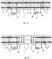
- Figure 1a shows a track which is built up of successive track sections 1 -1 - 1 - 1 +1 - etc.
- Each zone of the track may comprise one (usually several) track section 1 -1 - 1 - 1 +1 - etc.
- the track comprising the various sections is made up of rails 2a-2b, which are fixed to sleepers 3.
- the successive track sections are separated from each other by means of insulating connecting bridges 4, which are installed in one of the rails 2a-2b, or in both (as shown here).
- each track circuit of each track section is for that purpose built up of a power source 5, which is connected to each rail 2a, 2b via connections 5a, 5b, respectively.
- a dropout or rail relay 6 is provided, which is likewise electrically connected to the two rails 2a, 2b of the section in question via connections 6a, 6b, respectively.
- Figure 1b shows the situation in which a train 7 enters the track section 10 from the left, seen in the figure.
- the axles 7a of the train cause a short-circuit between the two rails 2a-2b, as a result of which current flows from the power source 5 via the connection 5a, the rail 2a, the axles 7a and back to the power source 5 via the other rail 2b and the connection 5b.
- This situation is shown in figure 1b .
- the track signals of the section comprising the track section 10 in question will be put in the stop position. Putting the signals in the stop position means that the zone in question is protected and
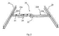
- Figure 2 shows a prior art shunt bar, which is provided with means 24 for activating and de-activating the shunt bar by remote control.
- the short-circuit 20 consists of two arm members which are hinged together by means of a hinge 22.
- the hinge makes it possible to install the bar between two rails 2a-2b, for example by exerting some pressure on the upper side of the bar using a foot. Following this, the bar will be securely clamped between the rails.
- the bar 20 comprises two contact parts 23a-23b, by means of which the bar is brought into electrical contact with the respective rails 2a-2b.
- the two arms of the bar are not continuously in electrical contact with each other, however, but they can be connected and disconnected by means of a control element present on the bar or by remote control from a communication module.
- the shunt bar Upon being connected, the shunt bar will bring the first rail 2a into electrical contact with the second rail 2b. As a result, the track zone in question will be decommissioned by indicating it to be in use and putting the signal in the stop position.
- the bar further comprises a monitoring module 25 for monitoring the short-circuit resistance between the two rails.
- the shunt bar shown in figure 2 is configured as a portable shunt bar. This means that it can be removed and be reused elsewhere for decommissioning a track zone at that location. In another embodiment, it may also form an integral part of a sleeper of the track and thus be permanently incorporated in the section. In yet another embodiment, it may also be accommodated near the track, for example in a junction box that is already present beside the track.
- the shunt bar 20 can communicate with a central processing unit using a communication module 24, and for example transmit the short-circuiting status to a control centre. Via the central processing unit, the communication module can also receive a command to activate and de-activate the shunt bar by remote control.
- the above description relates to a train detection system that is based on a track circuit system. Not all the tracks in the Netherlands, and certainly outside the Netherlands, make use of this system, however.
- the detection of trains in such other systems takes place by counting the number of axles, using an axle counter, at the beginning of a section or zone. If the number of detected axles at the beginning of the section equals the number of axles at the end of the section, it can be concluded that the train has left the section. In that case it can be determined that no train is present in the section and that the occupancy indication for that section no longer applies. Other trains can then enter the section again.
- axle counters also other detection systems are used, such as detection loops, pedals that are depressed when the train passes thereover, etc. The skilled person will appreciate what other systems are known and can be used.
- trains can also be detected on the basis of a GSM connection, for example by means of a GSM-R(rail) connection specially specified for trains.
- GSM-R(rail) connection specially specified for trains.
- newer mobile network standards such as 3G, 4G or specific train standards such as Future Railway Mobile Radio System, FRMRS.
- Figure 3 shows an embodiment of the invention of a decommissioning system that does not exhibit the above drawbacks.
- FIG 3 is a general view of several decommissioning systems 10, 10', 10" according to an embodiment of the invention.
- Two side-by-side track sections 1, 1' each comprising rails 2a, 2b (2a', 2b' and 2a", 2b") and a train signal 20 (20', 20"), for each local signal equipment building 101, 101', 101" are shown by way of illustration.
- the track section 1 (1', 1") is monitored for the presence of a train by means of a track circuit system (not shown), axle counter, GSM-R detection or other form of train detection. This detection can be transmitted, via cables 15a, 15b (15a', 15b' and 15a", 15b", respectively), to a train safety building such as a signal equipment building 101 (101', 101").
- interface means 15 (15', 15") are provided in this building, thus forming part of the train safety system, and by way of practical example in the signal equipment building, which interface means are directly physically connected to the train detection part of the train safety system.
- a decommissioning system according to the invention directly interferes with the train safety means (in the signal equipment buildings) rather than with the physical track, i.e. the rails.
- the interface means 15 (15', 15") are centrally provided directly near the train safety means in the signal equipment building 101 (101', 101 "), the risk of damage is reduced, among other things. After all, in comparison with a shunt bar installed in the track, a system that is installed in a signal equipment building is not exposed to extreme weather conditions (extreme cold, snow, ice, frost, rain, hail, extreme heat, etc) and is better protected against theft and vandalism. This has a positive respect as on the reliability and the safety of the system.
- a project for work on the track also called a working zone, may comprise one or more zones.
- Each zone comprises one or more clusters and each cluster comprises one or more sections. Sections are thus the smallest in size, followed by clusters and finally zones.
- the invention relates to the generation of an occupancy indication for at least one section, using the interface means. Within the scope of the present invention, at least one section is concerned, therefore.
- This project is also called a site safety instruction (SSI) of a clear track, zone or single section.
- SSI site safety instruction
- the design is made, verified and validated (for example at the office 100 via central server 150), and subsequently one SSP (site safety person) or a group of SSPs 150 can release the project via a local computer, tablet computer etc that is connected to the central server 150.
- the released project is then displayed to the COSS (controller of site safety) employee 150c, who may be on site.
- the COSS controller of site safety employee 150c
- the COSS controller of site safety employee 150c
- the SSP determines what, when, where, using what means, and how switching will take place by the COSS 150c.
- a green LED on the interface means 15 (15', 15" will blink.
- the decommissioning is cancelled by deactivating the project, which can be done by the COSS.
- the product can be given back and taken back so as to prevent the project still being displayed to a COSS 150c on duty.
- a product could thus be conceived at the office 100 and be verified and validated at said office, and a command to activate an occupancy indication on the train safety systems of only the signal equipment buildings 101 and 101" could be generated, so that the signals 20 and 20" for the sections associated with the rails 2a, 2b and 2a", 2b" will be put in the stop position and an occupancy indication will be activated.
- This command is made available to the COSS 150c via the central server.
- the COSS 150c is the person who is locally responsible for safety and who activates the decommissioning prior to the commencement of the work by logging into the server 150 (by personal authentication).
- the command is ready and is communicated to the decommissioning means and the interface means 15, 15" in the signal equipment buildings 101 and 101" via the communication means.
- the local decommissioning means interfere with the train safety system via the interface means 15, 15" for decommissioning the sections of the rails 2a, 2b and 2a", 2b".
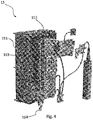
- the interface means 15 are shown in more detail in figure 4 .
- the control means 15 are preferably accommodated in an explosion-proof housing 151 and built up around a PCB 152, on which the necessary components are mounted.
- the housing with the interface means that is shown in figure 4 is to be interpreted solely as an example, however. Other variants thereto are also conceivable, which variants fall within the inventive concept and the scope of the appended claims.
- the variant shown in figure 4 is configured to be connected to a (B)-relay and concerns a single circuit.
- the interface means 15 can be many times more compact. Another advantage of electronic, not relay-based interface means is that multiple switching is possible therewith.
- the control means 15 are preferably supplied with power from a power source that forms part of the infrastructure 100-101 of the train safety system. In this way a reliable operation of the system is ensured, so that the safety of the rail workers in the case of a decommissioning is guaranteed.
- an auxiliary power source 153 is mounted on the PCB 152, so that the system need not be decommissioned but will continue to be operational in case of a malfunction in the train safety system and an undesirable failure of the main power source. This further contributes to safer working conditions for rail workers in and beside the track section 2-2' in question.
- the auxiliary power source 153 in particular comprises one or more batteries, which can be recharged by the main power source that forms part of the infrastructure 101-101 of the train safety system. In this way the functionality of the system according to the invention is at all times ensured, even in case of unexpected malfunctions.
- the decommissioning system 15 comprises decommissioning means, which generate an occupancy indication.
- the system further comprises communication means via which the system communicates with an interface or other form of communication over a network. This communication is shown in figure 3 and takes place between the central (web) server 150 and all the persons and apparatuses that can be connected thereto, such as the user 150c or a remote user 150a who can log into the server and read the status of the occupancy indication but also input an occupancy indication command.
- the user 150c can for example locally activate the occupancy indication command.
- the server 150 is further connected to the interface means 15, 15', 15" in the local signal equipment buildings 101, 101', 101" via the communication channels 17, 17', 17".
- the system further comprises control means which are configured to control the decommissioning means and to convert instructions received via the communication means into commands, so that the decommissioning means can be controlled on the basis thereof.
- the system 15 is configured to decommission a section or an entire zone of a track in a controlled manner by generating an occupancy indication.
- a shunt bar is placed between the rails
- the decommissioning means are placed inside a signal equipment building and consequently outside the risk area of the track.
- the interface means Via the interface means the system is hardwired to the train safety system in the signal equipment building and the switch, i.e. the decommissioning means, is remotely controlled by the control means, i.e. via the communication means, to effect the decommissioning and read whether it meets the requirements made thereof.
- the result is made available again, for example to the person responsible for the safety, via the communication means. All these means are locally housed in the signal equipment building 101, 101', 101", and linked together via the web server 150.
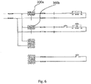
- Figure 5 is a block diagram showing the principle of operation of the system 15 according to one embodiment of the invention, which is specifically configured for being connected to a train safety system which comprises relays and which is switched (off) on the basis of said relays.
- the invention also provides a digital/electronic variant which is configured for being connected to a train safety system which does not comprise relays but which comprises PLCs or other computer-controlled/switched protection circuits, as is the case in an RBC.
- the interface means do not comprise conventional switches 211 and (failsafe) relays 213, but they are configured as digital means and control one or more sections simultaneously, for example via a computer interface over a UTP cable or the like.
- the invention also provides interface means that can be connected to a train safety system that comprises both PLCs and relays, however, for example a system in which the PLCs (digital/electronic) are controlled by the interface means and the PLCs subsequently control the relays.
- One or more components 210, 212, 214 may be configured as redundant components with a view to increasing the reliability and availability.
- Various components can be distinguished in the block diagram. Centrally arranged is the MCU, being a central processor (or several processors) 201, also called the control means, which controls and checks the entire system.
- the control means and the rest of the system are supplied with energy by the PSU 202.
- Said PSU is in turn supplied with power from a 12 V rail of the signal box or signal equipment building, for example, which is already present in the safety system.
- Watchdog 203 monitors the systems and checks whether the system still reacts. If it does not, the supply of power is briefly stopped, causing the system to restart.
- Logging 204 takes place internally for writing all events to an SD card, for example, or to another form of local storage.
- Indication 205 provides an indication whether the site is safe. It may to that end comprise an LED, which can blink green if the site is safe. A condition is that this includes not only detection whether the site is safe but also whether the system is functioning properly. Only in that case will a status report in the form of a blinking green LED be provided. As the skilled person will appreciate, these status reports may also be provided using different LEDs, colours or other signalling forms.
- switching to an occupancy indication can also take place manually by the manual 206 element. It may be provided with a key (see figure 4 , numeral 154), so that local switching of the occupancy indication can only take place if the correct key is used.
- the MCU 201 communicates with external means via a communication channel or via communication means 207 on the basis of a reliable protocol, such as the CP3000 protocol.
- a reliable protocol such as the CP3000 protocol.
- Other apparatuses available via the present applicant, such as an MTinfo, can co-operate with this system on the basis of such a protocol.
- Detection 208 detects whether the system is in the correct position, and control 209 controls the switch and it also checks whether the switch is indeed able to switch, which is done prior to the actual switching thereof.
- Drive 210 is used for driving the switch to switch individual segments to the correct position, and measure 212 is used for measuring whether the individual switching segments of the switch have been switched to the correct position. The result of this is transmitted to control block 209.
- Switch 211 carries out the actual activation. These can be remotely operated via the communication means, CP3000 and MCU, and in particular comprise a double redundant, bi-directional failsafe switch.
- the interface module is indicated at 213, it forms the interface between the rest of the system and in particular the decommissioning means in the form of the switch 211 on the one side and the interface with the train protection system in the signal equipment building on the other side.
- Feedback 214 combines the feedback from the signal equipment building with the internal feedback from the system and translates this into a detection status.
- the detection status may either be "safe” or “unsafe” (for the rail worker).
- the interface 214 to the signal box consists of a 2x normally open and 2x normally closed connection and the feedback connection.
- the communication means 207 make a connection with the web server 150 of figure 3 via a GPRS or Ethernet module 16 and make the information available to the users in question via said channel.
- GPRS and Ethernet are mentioned purely by way of illustration. The skilled person will appreciate that these terms refer to a wireless and a hardwired connection, respectively. Within that framework, the term GPRS is understood to include current standards but also new/future standards such as 3G and 4G.
- Ethernet is understood to mean a fixed connection that may already be present in the signal equipment building.
- the system may furthermore be provided with a GPS module 217, by means of which the system can be located and which is also suitable for synchronising the internal clock of the system.
- the communication means communicate (wirelessly or via a fixed connection) with the coordinating web-based management system 219, which is available as the MTinfo system from the present applicant. Via this system users can control the system via a web interface 220, and all the data in the system is safely written to a database 219. Using a remote control device, the system can be used at any location via remote 221 for decommissioning one (or several) zone(s) or section(s).
- the switch 211 may be configured as a so-called bi-directional failsafe switch.
- the switch is provided with a memory module, in which the actual operating status of the train simulation unit can be stored.
- the failsafe status of the bi-directional switch is that status which maintains safety in the track section in question.
- the train simulation unit is in functional operation and consequently simulates the presence of a train in a track section allocated to the system (and thus provides an occupancy indication to further trains) and the system gets out of operation due to a malfunction
- the bi-directional failsafe switch will maintain the "occupancy indication" rather than switch off automatically. In this way the safety of the rail workers in the track section in question is guaranteed, so that the last status will be maintained also in the case of a malfunction in the train simulation unit.
- the "non-functional operation" status is the failsafe status of the bi-directional switch, in which status the availability of the train protection system is maintained.
- the bi-directional switch is provided with two switch contacts 300a-300b.
- Contact 300a is a contact which is closed when the system, in particular the decommissioning means thereof, is not "on”.
- the switch contact 300b is open in that situation.
- the switch contact 300a will be open and the switch contact 300b will be closed.
- the system continuously monitors the status of the protection means (made up of the two switch contacts 300a-300b) and the system will not provide a "safe" indication until a closed contact has been detected.
- the communication interface is configured so that a situation in which both contacts are closed upon switching of the switch contacts 300a-300b cannot occur.
- the bi-directional switch is made up of a circuit with 2 Normally Closed and 2 Normally Open terminals. This provides an effective interface connection with all kinds of different types of train protection systems as indicated before and used in various countries.
- the status of the bi-directional switch is remotely monitored via the communication means, whilst also the status of the train protection system is continuously monitored. Periodically (for example every 0.5 seconds locally and every 3 seconds remotely via the communication means/network) the status of the switch is translated into a status for the user, which status may be "functional operation” or "non-functional operation”.
Claims (11)
- Système de mise hors service (15) pour la mise hors service de multiples sections d'une voie ferrée, dans lequel ledit système est composé d'un groupe de moyens d'interface (15) et de moyens de mise hors service (209), ledit système comprenant une pluralité de :- moyens de mise hors service (209) configurés pour mettre hors service au moins une section de la voie ferrée et la fermer aux trains en générant une indication d'occupation ;- moyens de communication (207) configurés pour recevoir un ordre de mise hors service de l'au moins une section de la voie ferrée et pour délivrer des informations d'état concernant une section de la voie ferrée qui a été ou non mise hors service ;- moyens de commande (201) configurés pour commander les moyens de mise hors service pour mettre hors service l'au moins une section de voie ferrée sur la base dudit ordre ; et- moyens d'interface (210, 211, 212, 213, 214) qui peuvent être physiquement reliés (213, 214) à un système de sécurité ferroviaire de la voie ferrée d'une part et aux moyens de mise hors service (209) d'autre part et qui sont configurés pour activer la mise hors service de la section de la voie ferrée dans le niveau de surveillance de sécurité des trains sur la base dudit ordre en générant une indication d'occupation au système de sécurité ferroviaire :
dans lequel au moins chaque moyen d'interface et chaque moyen de mise hors service sont logés dans différents boîtiers d'un système de sécurité ferroviaire, ou logés dans différents bâtiments d'équipement de signalisation dudit système de sécurité ferroviaire, de sorte que chaque boîtier ou bâtiment d'équipement de signalisation soit muni d'un moyen d'interface et d'un moyen de mise hors service associé, pour que ledit système mette hors service lesdites multiples sections associées à différents boîtiers de systèmes de sécurité ferroviaire ou à différents bâtiments d'équipement de signalisation, et que chacun desdits moyens d'interface et desdits moyens de mise hors service mettent hors service une section respective desdites multiples sections sur la base d'un seul ordre de mise hors service. - Système de mise hors service (15) selon l'une quelconque des revendications précédentes, dans lequel les moyens d'interface (210, 211, 212, 213, 214) sont configurés pour être reliés à un ou plusieurs relais et/ou PLC et/ou RBC et/ou ASK du système de sécurité ferroviaire.
- Système de mise hors service (15) selon l'une quelconque des revendications précédentes, dans lequel les moyens d'interface (210, 211, 212, 213, 214) sont configurés pour générer une indication d'occupation au système de sécurité ferroviaire et, en particulier, relire l'état d'une indication d'occupation à partir du système de sécurité ferroviaire et/ou pour générer un ordre de commande d'aiguillage au système de sécurité ferroviaire et, en particulier, relire l'état d'un ordre de commande d'aiguillage à partir du système de sécurité ferroviaire et/ou pour générer un ordre de commande de signal au système de sécurité ferroviaire et, en particulier, relire l'état d'un ordre de commande de signal à partir du système de sécurité ferroviaire.
- Système de mise hors service (15) selon la revendication 3, dans lequel les moyens de communication (207) sont configurés pour communiquer l'état de l'indication d'occupation comme lu aux moyens de signalisation, lesquels moyens de signalisation sont configurés pour produire des signaux lumineux au niveau de la section de la voie ferrée qui a été mise hors service.
- Système de mise hors service (15) selon l'une quelconque des revendications précédentes, dans lequel le système de mise hors service (15) est relié à au moins une source d'alimentation du système de sécurité ferroviaire et en particulier également à une source d'alimentation auxiliaire supplémentaire (202).
- Système de mise hors service (15) selon la revendication 5, dans lequel l'alimentation auxiliaire (202) comprend une batterie, et dans lequel la batterie peut en particulier être chargée par la source d'alimentation du système de sécurité ferroviaire.
- Système de mise hors service (15) selon l'une quelconque des revendications précédentes, dans lequel les moyens d'interface (210, 211, 212, 213, 214) sont configurés pour former un groupe d'interfaces avec un ou plusieurs autres moyens d'interface (210, 211, 212, 213, 214), lequel groupe d'interfaces peut être commandé par l'un d'une multitude de moyens de commande (201).
- Système de mise hors service (15) selon l'une quelconque des revendications précédentes, dans lequel les moyens d'interface (210, 211, 212, 213, 214) comprennent un ou plusieurs aiguillages à sécurité intégrée (213), en particulier des aiguillages à sécurité intégrée bidirectionnels, et plus particulièrement un double aiguillage normalement fermé et un double aiguillage normalement ouvert (300a, 300b).
- Système de mise hors service (15) selon l'une quelconque des revendications précédentes, dans lequel les moyens de commande (201) sont configurés pour recevoir un signal de libération provenant des moyens de communication (207) et pour commander les moyens de mise hors service (209) pour mettre hors service l'au moins une section de la voie ferrée sur la base de l'ordre de mise hors service uniquement à la réception dudit signal.
- Système de mise hors service (15) selon l'une quelconque des revendications précédentes, dans lequel les moyens de mise hors service (209) sont configurés pour mettre hors service l'au moins une section de la voie ferrée sur la base d'un ou de plusieurs du groupe comprenant : la programmation d'un ou de plusieurs trains, le fait de mettre un ou plusieurs signaux en position d'arrêt, le blocage d'un ou de plusieurs aiguillages et la simulation de la présence d'un train dans l'au moins une section de la voie ferrée.
- Moyens d'interface (210, 211, 212, 213, 214) pour un système de mise hors service (15) selon l'une quelconque des revendications précédentes.
Applications Claiming Priority (2)
| Application Number | Priority Date | Filing Date | Title |
|---|---|---|---|
| NL2013372 | 2014-08-27 | ||
| NL2013825A NL2013825B1 (nl) | 2014-11-18 | 2014-11-18 | Een buitendienststellingssysteem voor het buitendienststellen van een sectie van railbaan, alsmede interfacemiddelen voor het aansluiten van een buitendienststellingssysteem op een treinbeveiligingssysteem van de railbaan. |
Publications (2)
| Publication Number | Publication Date |
|---|---|
| EP2990296A1 EP2990296A1 (fr) | 2016-03-02 |
| EP2990296B1 true EP2990296B1 (fr) | 2023-01-25 |
Family
ID=53785575
Family Applications (1)
| Application Number | Title | Priority Date | Filing Date |
|---|---|---|---|
| EP15181063.7A Active EP2990296B1 (fr) | 2014-08-27 | 2015-08-14 | Système de mise hors service d'une section de rail de chemin de fer, ainsi que des moyens d'interface pour la connexion d'un tel système à un système de sécurité de train de la voie ferrée |
Country Status (2)
| Country | Link |
|---|---|
| EP (1) | EP2990296B1 (fr) |
| ES (1) | ES2942689T3 (fr) |
Families Citing this family (2)
| Publication number | Priority date | Publication date | Assignee | Title |
|---|---|---|---|---|
| CN107689811A (zh) * | 2017-09-19 | 2018-02-13 | 天津七二通信广播股份有限公司 | 支持450m模拟同异频通信和mpt1327集群功能的通信单元及实现方法 |
| NL2024384B1 (nl) | 2018-12-05 | 2020-08-31 | Volkerwessels Intellectuele Eigendom B V | Bewaken van een spoorbaan voor werkplekbeveiliging. |
Citations (1)
| Publication number | Priority date | Publication date | Assignee | Title |
|---|---|---|---|---|
| DE19850172A1 (de) | 1998-01-19 | 1999-07-22 | Tekfer S A S Di Piero Ing Mont | Zentrale Steuerungsvorrichtung für die Fahrtverlangsamung auf einem Teilstück einer Eisenbahnlinie |
Family Cites Families (8)
| Publication number | Priority date | Publication date | Assignee | Title |
|---|---|---|---|---|
| DE50109154D1 (de) * | 2001-10-26 | 2006-05-04 | Alcatel Sa | Vorrichtung zur Rottenwarnung |
| FR2879550B1 (fr) * | 2004-12-21 | 2014-04-11 | Alstom Belgium Sa | Installation de protection des travailleurs en voie |
| NL1030622C1 (nl) * | 2005-12-08 | 2007-06-11 | D D Idea V O F | De uitvinding betreft een systeem voor het tijdig waarschuwen van weggebruikers voor aankomende trams of andersoortig rail verkeer, bestaand uit een direct naast de rails ingebouwde rubberen/kunststoffen sleeve, met een daarin ingegoten LED of andersoortige verlichting, elektronisch aangesloten en aangestuurd op het rail systeem. |
| NL1033077C2 (nl) | 2006-12-18 | 2008-06-19 | Dual Inventive V O F | Detectie-inrichting van een kortsluitingsbrug. |
| FR2951425A1 (fr) * | 2009-10-16 | 2011-04-22 | El Hadj Mohamed Ait | Dispositif lumineux securisant la voie de circulation du tramway |
| JP5769425B2 (ja) * | 2011-01-11 | 2015-08-26 | 三菱重工業株式会社 | 制御システムおよび制御装置 |
| GB201104009D0 (en) * | 2011-03-09 | 2011-04-20 | Sharing Alfred | Indication system for railways and roads |
| NL2012356B1 (nl) * | 2013-03-04 | 2016-07-15 | Volkerrail Nederland Bv | Buitendienstneming van een stuk spoorweg met behoud van onderscheid naar herkomst in de bij de treindienstregeling aankomende datastroom. |
-
2015
- 2015-08-14 EP EP15181063.7A patent/EP2990296B1/fr active Active
- 2015-08-14 ES ES15181063T patent/ES2942689T3/es active Active
Patent Citations (1)
| Publication number | Priority date | Publication date | Assignee | Title |
|---|---|---|---|---|
| DE19850172A1 (de) | 1998-01-19 | 1999-07-22 | Tekfer S A S Di Piero Ing Mont | Zentrale Steuerungsvorrichtung für die Fahrtverlangsamung auf einem Teilstück einer Eisenbahnlinie |
Also Published As
| Publication number | Publication date |
|---|---|
| EP2990296A1 (fr) | 2016-03-02 |
| ES2942689T3 (es) | 2023-06-05 |
Similar Documents
| Publication | Publication Date | Title |
|---|---|---|
| CN104442931B (zh) | 轨道交通综合维护管理系统 | |
| CN103707904B (zh) | 一种城轨cbtc模式下的临时限速方法及限速系统 | |
| WO2006051355A1 (fr) | Systeme de commande, procede de fonctionnement d'un systeme de commande, signal de donnees informatiques et interface utilisateur graphique pour vehicules sur rails | |
| CN107161180B (zh) | 新型控制、监督、监测一体化的驼峰全电子自动化系统 | |
| CN103754242A (zh) | 市域铁路信号系统及其控制方法 | |
| CN103745624A (zh) | 轨道交通模拟系统 | |
| US11130508B2 (en) | Solar powered cell network switch point indicator system | |
| Saitov et al. | Improvement of control devices for road sections of railway automation and telemechanics | |
| CN101592948A (zh) | 一种具有现地控制的区域计算机联锁控制方法 | |
| EP3663162A1 (fr) | Assurer la sécurité pour travaux près de la voie | |
| EP2990296B1 (fr) | Système de mise hors service d'une section de rail de chemin de fer, ainsi que des moyens d'interface pour la connexion d'un tel système à un système de sécurité de train de la voie ferrée | |
| KR101340080B1 (ko) | 열차제어시스템에서 계전기를 이용한 주계로의 자동절체장치 | |
| US20040049327A1 (en) | Radio based automatic train control system using universal code | |
| EP1814768A2 (fr) | Systeme de securite de passage a niveau | |
| EP2857277B1 (fr) | Sécurisation de franchissement de niveau ferroviaire programmable avec couplage de communication aux équipements périphériques intelligents externes et procédé de régulation de l'activité de cet équipement | |
| RU2622522C1 (ru) | Мобильный комплекс микропроцессорной системы управления стрелками и светофорами участка железной дороги | |
| KR101210930B1 (ko) | 열차용 선로변 다중화 정보처리모듈의 자동 절체제어기 감시 및 통신유지장치 | |
| Dimitrova | Analysis of automatic control systems for metro trains | |
| NL2013825B1 (nl) | Een buitendienststellingssysteem voor het buitendienststellen van een sectie van railbaan, alsmede interfacemiddelen voor het aansluiten van een buitendienststellingssysteem op een treinbeveiligingssysteem van de railbaan. | |
| KR100673535B1 (ko) | 열차용 선로변의 정보처리모듈 다중화에 따른 절체 시스템및 그 방법 | |
| RU102579U1 (ru) | Микропроцессорная централизация стрелок и сигналов мпцт | |
| RU2417915C1 (ru) | Система логического контроля за действиями оперативного персонала и состоянием технических средств электрической централизации | |
| CN214372347U (zh) | 一种铁路桥梁灾害防护信号系统 | |
| WO2014175768A1 (fr) | Dispositif de suivi et de commande à distance de l'équipement des wagons de transport férroviaire | |
| Bezabih | Automatic train control standard for Ethiopia |
Legal Events
| Date | Code | Title | Description |
|---|---|---|---|
| PUAI | Public reference made under article 153(3) epc to a published international application that has entered the european phase |
Free format text: ORIGINAL CODE: 0009012 |
|
| AK | Designated contracting states |
Kind code of ref document: A1 Designated state(s): AL AT BE BG CH CY CZ DE DK EE ES FI FR GB GR HR HU IE IS IT LI LT LU LV MC MK MT NL NO PL PT RO RS SE SI SK SM TR |
|
| AX | Request for extension of the european patent |
Extension state: BA ME |
|
| 17P | Request for examination filed |
Effective date: 20160728 |
|
| RBV | Designated contracting states (corrected) |
Designated state(s): AL AT BE BG CH CY CZ DE DK EE ES FI FR GB GR HR HU IE IS IT LI LT LU LV MC MK MT NL NO PL PT RO RS SE SI SK SM TR |
|
| STAA | Information on the status of an ep patent application or granted ep patent |
Free format text: STATUS: EXAMINATION IS IN PROGRESS |
|
| 17Q | First examination report despatched |
Effective date: 20181122 |
|
| STAA | Information on the status of an ep patent application or granted ep patent |
Free format text: STATUS: EXAMINATION IS IN PROGRESS |
|
| STAA | Information on the status of an ep patent application or granted ep patent |
Free format text: STATUS: EXAMINATION IS IN PROGRESS |
|
| GRAP | Despatch of communication of intention to grant a patent |
Free format text: ORIGINAL CODE: EPIDOSNIGR1 |
|
| STAA | Information on the status of an ep patent application or granted ep patent |
Free format text: STATUS: GRANT OF PATENT IS INTENDED |
|
| INTG | Intention to grant announced |
Effective date: 20220816 |
|
| GRAS | Grant fee paid |
Free format text: ORIGINAL CODE: EPIDOSNIGR3 |
|
| GRAA | (expected) grant |
Free format text: ORIGINAL CODE: 0009210 |
|
| STAA | Information on the status of an ep patent application or granted ep patent |
Free format text: STATUS: THE PATENT HAS BEEN GRANTED |
|
| AK | Designated contracting states |
Kind code of ref document: B1 Designated state(s): AL AT BE BG CH CY CZ DE DK EE ES FI FR GB GR HR HU IE IS IT LI LT LU LV MC MK MT NL NO PL PT RO RS SE SI SK SM TR |
|
| REG | Reference to a national code |
Ref country code: GB Ref legal event code: FG4D |
|
| REG | Reference to a national code |
Ref country code: CH Ref legal event code: EP |
|
| REG | Reference to a national code |
Ref country code: AT Ref legal event code: REF Ref document number: 1545725 Country of ref document: AT Kind code of ref document: T Effective date: 20230215 Ref country code: IE Ref legal event code: FG4D |
|
| REG | Reference to a national code |
Ref country code: DE Ref legal event code: R096 Ref document number: 602015082361 Country of ref document: DE |
|
| REG | Reference to a national code |
Ref country code: NL Ref legal event code: FP |
|
| REG | Reference to a national code |
Ref country code: LT Ref legal event code: MG9D |
|
| REG | Reference to a national code |
Ref country code: ES Ref legal event code: FG2A Ref document number: 2942689 Country of ref document: ES Kind code of ref document: T3 Effective date: 20230605 |
|
| REG | Reference to a national code |
Ref country code: AT Ref legal event code: MK05 Ref document number: 1545725 Country of ref document: AT Kind code of ref document: T Effective date: 20230125 |
|
| P01 | Opt-out of the competence of the unified patent court (upc) registered |
Effective date: 20230527 |
|
| PG25 | Lapsed in a contracting state [announced via postgrant information from national office to epo] |
Ref country code: RS Free format text: LAPSE BECAUSE OF FAILURE TO SUBMIT A TRANSLATION OF THE DESCRIPTION OR TO PAY THE FEE WITHIN THE PRESCRIBED TIME-LIMIT Effective date: 20230125 Ref country code: PT Free format text: LAPSE BECAUSE OF FAILURE TO SUBMIT A TRANSLATION OF THE DESCRIPTION OR TO PAY THE FEE WITHIN THE PRESCRIBED TIME-LIMIT Effective date: 20230525 Ref country code: NO Free format text: LAPSE BECAUSE OF FAILURE TO SUBMIT A TRANSLATION OF THE DESCRIPTION OR TO PAY THE FEE WITHIN THE PRESCRIBED TIME-LIMIT Effective date: 20230425 Ref country code: LV Free format text: LAPSE BECAUSE OF FAILURE TO SUBMIT A TRANSLATION OF THE DESCRIPTION OR TO PAY THE FEE WITHIN THE PRESCRIBED TIME-LIMIT Effective date: 20230125 Ref country code: LT Free format text: LAPSE BECAUSE OF FAILURE TO SUBMIT A TRANSLATION OF THE DESCRIPTION OR TO PAY THE FEE WITHIN THE PRESCRIBED TIME-LIMIT Effective date: 20230125 Ref country code: HR Free format text: LAPSE BECAUSE OF FAILURE TO SUBMIT A TRANSLATION OF THE DESCRIPTION OR TO PAY THE FEE WITHIN THE PRESCRIBED TIME-LIMIT Effective date: 20230125 Ref country code: AT Free format text: LAPSE BECAUSE OF FAILURE TO SUBMIT A TRANSLATION OF THE DESCRIPTION OR TO PAY THE FEE WITHIN THE PRESCRIBED TIME-LIMIT Effective date: 20230125 |
|
| PG25 | Lapsed in a contracting state [announced via postgrant information from national office to epo] |
Ref country code: SE Free format text: LAPSE BECAUSE OF FAILURE TO SUBMIT A TRANSLATION OF THE DESCRIPTION OR TO PAY THE FEE WITHIN THE PRESCRIBED TIME-LIMIT Effective date: 20230125 Ref country code: PL Free format text: LAPSE BECAUSE OF FAILURE TO SUBMIT A TRANSLATION OF THE DESCRIPTION OR TO PAY THE FEE WITHIN THE PRESCRIBED TIME-LIMIT Effective date: 20230125 Ref country code: IS Free format text: LAPSE BECAUSE OF FAILURE TO SUBMIT A TRANSLATION OF THE DESCRIPTION OR TO PAY THE FEE WITHIN THE PRESCRIBED TIME-LIMIT Effective date: 20230525 Ref country code: GR Free format text: LAPSE BECAUSE OF FAILURE TO SUBMIT A TRANSLATION OF THE DESCRIPTION OR TO PAY THE FEE WITHIN THE PRESCRIBED TIME-LIMIT Effective date: 20230426 Ref country code: FI Free format text: LAPSE BECAUSE OF FAILURE TO SUBMIT A TRANSLATION OF THE DESCRIPTION OR TO PAY THE FEE WITHIN THE PRESCRIBED TIME-LIMIT Effective date: 20230125 |
|
| PGFP | Annual fee paid to national office [announced via postgrant information from national office to epo] |
Ref country code: NL Payment date: 20230821 Year of fee payment: 9 |
|
| REG | Reference to a national code |
Ref country code: DE Ref legal event code: R026 Ref document number: 602015082361 Country of ref document: DE |
|
| PLBI | Opposition filed |
Free format text: ORIGINAL CODE: 0009260 |
|
| PG25 | Lapsed in a contracting state [announced via postgrant information from national office to epo] |
Ref country code: SM Free format text: LAPSE BECAUSE OF FAILURE TO SUBMIT A TRANSLATION OF THE DESCRIPTION OR TO PAY THE FEE WITHIN THE PRESCRIBED TIME-LIMIT Effective date: 20230125 Ref country code: RO Free format text: LAPSE BECAUSE OF FAILURE TO SUBMIT A TRANSLATION OF THE DESCRIPTION OR TO PAY THE FEE WITHIN THE PRESCRIBED TIME-LIMIT Effective date: 20230125 Ref country code: EE Free format text: LAPSE BECAUSE OF FAILURE TO SUBMIT A TRANSLATION OF THE DESCRIPTION OR TO PAY THE FEE WITHIN THE PRESCRIBED TIME-LIMIT Effective date: 20230125 Ref country code: DK Free format text: LAPSE BECAUSE OF FAILURE TO SUBMIT A TRANSLATION OF THE DESCRIPTION OR TO PAY THE FEE WITHIN THE PRESCRIBED TIME-LIMIT Effective date: 20230125 Ref country code: CZ Free format text: LAPSE BECAUSE OF FAILURE TO SUBMIT A TRANSLATION OF THE DESCRIPTION OR TO PAY THE FEE WITHIN THE PRESCRIBED TIME-LIMIT Effective date: 20230125 |
|
| PGFP | Annual fee paid to national office [announced via postgrant information from national office to epo] |
Ref country code: IT Payment date: 20230825 Year of fee payment: 9 Ref country code: GB Payment date: 20230822 Year of fee payment: 9 |
|
| PLAX | Notice of opposition and request to file observation + time limit sent |
Free format text: ORIGINAL CODE: EPIDOSNOBS2 |
|
| 26 | Opposition filed |
Opponent name: VOESTALPINE SIGNALING UK LTD. Effective date: 20231025 |
|
| PG25 | Lapsed in a contracting state [announced via postgrant information from national office to epo] |
Ref country code: SK Free format text: LAPSE BECAUSE OF FAILURE TO SUBMIT A TRANSLATION OF THE DESCRIPTION OR TO PAY THE FEE WITHIN THE PRESCRIBED TIME-LIMIT Effective date: 20230125 |
|
| PGFP | Annual fee paid to national office [announced via postgrant information from national office to epo] |
Ref country code: FR Payment date: 20230824 Year of fee payment: 9 Ref country code: DE Payment date: 20230821 Year of fee payment: 9 Ref country code: BE Payment date: 20230821 Year of fee payment: 9 |
|
| PGFP | Annual fee paid to national office [announced via postgrant information from national office to epo] |
Ref country code: ES Payment date: 20231027 Year of fee payment: 9 |
|
| PG25 | Lapsed in a contracting state [announced via postgrant information from national office to epo] |
Ref country code: SI Free format text: LAPSE BECAUSE OF FAILURE TO SUBMIT A TRANSLATION OF THE DESCRIPTION OR TO PAY THE FEE WITHIN THE PRESCRIBED TIME-LIMIT Effective date: 20230125 |
|
| PLBB | Reply of patent proprietor to notice(s) of opposition received |
Free format text: ORIGINAL CODE: EPIDOSNOBS3 |
|
| PG25 | Lapsed in a contracting state [announced via postgrant information from national office to epo] |
Ref country code: MC Free format text: LAPSE BECAUSE OF FAILURE TO SUBMIT A TRANSLATION OF THE DESCRIPTION OR TO PAY THE FEE WITHIN THE PRESCRIBED TIME-LIMIT Effective date: 20230125 |
|
| REG | Reference to a national code |
Ref country code: CH Ref legal event code: PL |
|
| PG25 | Lapsed in a contracting state [announced via postgrant information from national office to epo] |
Ref country code: MC Free format text: LAPSE BECAUSE OF FAILURE TO SUBMIT A TRANSLATION OF THE DESCRIPTION OR TO PAY THE FEE WITHIN THE PRESCRIBED TIME-LIMIT Effective date: 20230125 |
|
| PG25 | Lapsed in a contracting state [announced via postgrant information from national office to epo] |
Ref country code: LU Free format text: LAPSE BECAUSE OF NON-PAYMENT OF DUE FEES Effective date: 20230814 |
|
| PG25 | Lapsed in a contracting state [announced via postgrant information from national office to epo] |
Ref country code: LU Free format text: LAPSE BECAUSE OF NON-PAYMENT OF DUE FEES Effective date: 20230814 Ref country code: CH Free format text: LAPSE BECAUSE OF NON-PAYMENT OF DUE FEES Effective date: 20230831 |