EP2989641B1 - Câble de données à haut débit - Google Patents
Câble de données à haut débit Download PDFInfo
- Publication number
- EP2989641B1 EP2989641B1 EP14720520.7A EP14720520A EP2989641B1 EP 2989641 B1 EP2989641 B1 EP 2989641B1 EP 14720520 A EP14720520 A EP 14720520A EP 2989641 B1 EP2989641 B1 EP 2989641B1
- Authority
- EP
- European Patent Office
- Prior art keywords
- speed data
- conductors
- data cable
- core
- cable according
- Prior art date
- Legal status (The legal status is an assumption and is not a legal conclusion. Google has not performed a legal analysis and makes no representation as to the accuracy of the status listed.)
- Active
Links
Images


Classifications
-
- H—ELECTRICITY
- H01—ELECTRIC ELEMENTS
- H01B—CABLES; CONDUCTORS; INSULATORS; SELECTION OF MATERIALS FOR THEIR CONDUCTIVE, INSULATING OR DIELECTRIC PROPERTIES
- H01B7/00—Insulated conductors or cables characterised by their form
- H01B7/30—Insulated conductors or cables characterised by their form with arrangements for reducing conductor losses when carrying alternating current, e.g. due to skin effect
- H01B7/303—Conductors comprising interwire insulation
-
- H—ELECTRICITY
- H01—ELECTRIC ELEMENTS
- H01B—CABLES; CONDUCTORS; INSULATORS; SELECTION OF MATERIALS FOR THEIR CONDUCTIVE, INSULATING OR DIELECTRIC PROPERTIES
- H01B11/00—Communication cables or conductors
- H01B11/02—Cables with twisted pairs or quads
- H01B11/04—Cables with twisted pairs or quads with pairs or quads mutually positioned to reduce cross-talk
-
- H—ELECTRICITY
- H01—ELECTRIC ELEMENTS
- H01B—CABLES; CONDUCTORS; INSULATORS; SELECTION OF MATERIALS FOR THEIR CONDUCTIVE, INSULATING OR DIELECTRIC PROPERTIES
- H01B11/00—Communication cables or conductors
- H01B11/002—Pair constructions
-
- H—ELECTRICITY
- H01—ELECTRIC ELEMENTS
- H01B—CABLES; CONDUCTORS; INSULATORS; SELECTION OF MATERIALS FOR THEIR CONDUCTIVE, INSULATING OR DIELECTRIC PROPERTIES
- H01B11/00—Communication cables or conductors
- H01B11/18—Coaxial cables; Analogous cables having more than one inner conductor within a common outer conductor
-
- H—ELECTRICITY
- H01—ELECTRIC ELEMENTS
- H01B—CABLES; CONDUCTORS; INSULATORS; SELECTION OF MATERIALS FOR THEIR CONDUCTIVE, INSULATING OR DIELECTRIC PROPERTIES
- H01B3/00—Insulators or insulating bodies characterised by the insulating materials; Selection of materials for their insulating or dielectric properties
- H01B3/18—Insulators or insulating bodies characterised by the insulating materials; Selection of materials for their insulating or dielectric properties mainly consisting of organic substances
- H01B3/30—Insulators or insulating bodies characterised by the insulating materials; Selection of materials for their insulating or dielectric properties mainly consisting of organic substances plastics; resins; waxes
-
- H—ELECTRICITY
- H01—ELECTRIC ELEMENTS
- H01B—CABLES; CONDUCTORS; INSULATORS; SELECTION OF MATERIALS FOR THEIR CONDUCTIVE, INSULATING OR DIELECTRIC PROPERTIES
- H01B7/00—Insulated conductors or cables characterised by their form
- H01B7/02—Disposition of insulation
Definitions
- the present invention relates to a high-speed data cable.
- Typical data transmission cables are more or less rigid coaxial cables, in which an inner conductor is surrounded by a cylindrical outer conductor, and more flexible, differential (symmetrical) cables, in which positive and negative wires are laid parallel to one another.
- the wires can be a solid single conductor or strands of several conductors. The wires are separated from each other by an insulating material. In a strand, the conductors can be loosely next to each other or twisted.
- the differential pair may itself (sheathed) form a cable or form a cable with several other differential pairs in a bundle.
- the WO2009129028 describes a conductor comprising a central element having a length, a plurality of insulated strands disposed about the central element in at least a first and a second concentric layer, and a layer of dielectric material having a propagation velocity around the plurality of isolated strands is arranged around.
- Each of the plurality of insulated strands has a conductive element and a layer of insulating material disposed about the conductive element and a length approximately equal to an inverse of the propagation velocity of the associated dielectric materials multiplied by the product of the length of the central element and the number one hundred.
- the object of the present invention is to provide an improved high-speed data cable, which allows a high-rate (high-frequency) data transmission.
- the core idea of the present invention is to have realized that it is possible to more efficiently enable high-frequency data transmission in a high-speed data cable, resulting in lower attenuation, especially at high frequencies.
- the high-speed data cable comprises at least one pair of wires, with a conductive shield surrounding the wires.
- the conductive shielding results in an increased immunity to interference of the cable, which, inter alia, a faster data transmission is possible.
- An insulating cable sheath encloses the conductive shield and protects the cable from mechanical stress and corrosion, among other things.
- Each of the wires comprises at least three electrical conductors insulated from one another, wherein the conductors are arranged to extend in an equidistant manner to a longitudinal central axis of the respective core.
- the skin effect refers to the narrowing of the signal current in ever smaller space (near or at the conductor surface) at higher frequencies. Effectively, the conductor cross-section available for the current transport decreases or the ohmic resistance increases with increasing frequency. The skin effect thus leads to a high signal attenuation, especially at high frequencies.
- Fig. 1 shows a cross-section of an embodiment of a high-speed data cable 100, hereinafter also referred to as cable 100.
- the cable 100 includes at least one wire pair 102. It is exemplarily designed as a differential (symmetrical) cable in which the two wires 104a, 104b of the wire pair 102 are parallel to one another in an axial direction.
- the two wires 104a, 104b of the wire pair 102 have a differential push-pull impedance and a common mode impedance.
- the transmission of a useful signal takes place in that the difference between the two wires 104a, 104b represents the useful signal.
- a useful signal In contrast, in the case of asymmetrical cables, transmission takes place by means of a useful signal whose value changes with respect to a reference potential (ground).
- the useful signal may have a voltage potential and / or a current strength.
- the useful signal In symmetric signal transmission, the useful signal, especially in the high frequency range, less prone to interference on a transmission link. At high frequencies disturbances interfere more easily, because eg the screen attenuation decreases. Asymmetric cables can not compensate for this.
- the coupling of interference in practice is still reduced by the earth unbalance attenuation. Earth imbalance damping indicates the deviation from the theoretically ideal equality of the positive and negative wires.
- the disturbing influences for example due to capacitive or inductive couplings on the transmission path, are approximately equal in the case of the symmetrical signal transmission on both cores 104a, 104b, so that the disturbance almost disappears during the subtraction of the two signals of the cores 104a, 104b.
- a conductive shield 108 longitudinally surrounds the wires 104a, 104b and forms a Faraday cage around the wires 104a, 104b.
- the wires 104a, 104b may each be surrounded in pairs by a common conductive shield 108. Alternatively, an individual shield per vein or a plurality of veins would be possible together.
- the cores 104a, 104b are protected against external alternating electromagnetic fields by the Faraday cage. That capacitive or inductive couplings of interference to the cable 100 are prevented or at least reduced.
- the Faraday cage of the shield 108 prevents the cores 104a, 104b from transmitting AC electromagnetic fields, thereby further protecting the cores 104a, 104b of the cable 100 and the environment of the cable 100 from electromagnetic emission.
- the conductive shield 108 may be made of any conductive material.
- the conductive shield 108 is metal clad Plastic film or formed from non-insulated metal wires.
- the conductive shield 108 may each at least one wire pair 102 in any form, for example. Wrapped or braided surrounded.
- the conductive shield 108 is a wire mesh in which individual, mutually non-insulated metal wires are overlaid or a plastic-laminated metal foil which is wound around the wires 104a, 104b.
- the conductive shield 108 is fabricated depending on the desired mechanical flexibility and / or the required electrical shielding characteristic of the cable 100.
- the conductive screen 108 may be fabricated as a closed / solid shell or as a combination of the previously described elements.
- the wires 104a, 104b may be twisted together, i. the wires 104a, 104b are twisted in the longitudinal direction about a common axis.
- the twisting of the wires 104a, 104b favors the symmetrical properties of the cable 100. Interferences which act on the wires 104a, 104b from a certain direction, for example, are impressed identically on both wires 104a, 104b of the wire pair 102.
- the individual wire pairs 102 in the cable 100 can be twisted to different degrees with each other. As a result, coupling in of interference of the wire pairs 102 with one another is reduced.
- An insulating sheath 106 encloses the conductive shield 108 and forms the surface of the cable 100.
- the insulating sheath 106 may be made of, for example, polyvinyl chloride (PVC), polypropylene (PP), polyethylene (PE), or other insulating material.
- the insulating sheathing 106 completely encloses the conductive shield 108 and prevents electrical connection between the conductive shield 108 and the environment of the cable 100.
- the insulating sheath 106 protects the cable 100 from chemical or mechanical influences that may result in damage to the cable 100 , For example, the insulating sheath 106 may be extruded onto the conductive shield 108.
- Fig. 1 shows a first implementation form of a wire 104a, 104b, which comprises three electrical conductors 110.
- the conductors 110 may be made of any electrically conductive material.
- the electrical conductors 110 are made of metal, such as copper or aluminum or copper or aluminum alloys. Copper and aluminum have a low electrical resistivity, which makes them particularly suitable as electrical conductors.
- copper and aluminum have a low electrical resistivity, which makes them particularly suitable as electrical conductors.
- aluminum exhibits a low mass density and thus a low specific weight, whereby the weight of the cable 100 can be kept low.
- the conductors 110 are arranged equidistant (with the same distance) to a longitudinal central axis 118 of the respective wire 104a, 104b.
- a circular arrangement of the conductors 110 around a center of the wires 104a, 104b or the centers of the wires 110 are arranged on a circle around the longitudinal central axis 118.
- the conductors 110 are twisted in each strand 104a, 104b or arranged twisted around the longitudinal center axis 118. Twisting the conductors 110 increases the flexibility of the wires 104a, 104b, i.
- the more twisted the conductors 110 in the wire 104a, 104b the more flexible the wire 104a, 104b can bend, allowing smaller bend radii with the wire 104a, 104b without breaking the wires 110 in the wire 104a, 104b.
- the same electrical (environmental) conditions are achieved for all conductors. However, a stronger twisting leads at the same time to a greater effective conductor length with the same outer length of the cable.
- the individual conductors 110 of a wire are each short-circuited. This can e.g. done by soldering or crimping.
- a plurality of conductors 110 may be arranged equidistantly in the wire 104a, 104b.
- a wire comprises 3 to 18 conductors 110.
- Each conductor 110 adjoins on its outer surface at least one insulating material, in which the conductors 110 of the respective core 104a, 104b run separately from one another.
- the insulating material encloses the conductor 110 and prevents electrical currents between the conductors 110.
- the insulating material between the conductors 110 reduces the influence of the skin effect.
- the skin effect occurs when an electrical conductor with a higher-frequency alternating current flows through it.
- the current density inside the conductor is lower than at the surface.
- the displacement of the current to the surface increases with increasing frequency. This leads to unwanted attenuation of an electrical cable.
- the insulation of the individual conductors against each other increases the effective surface area while maintaining the same cross section. Instead of a single conductor are several small electrical conductors available, creating a larger surface. This leads to an effectively higher conductor cross section at high frequencies. This results in a lower damping in the respective wire 104a, 104b.
- the conductors 110 of the wires 104a, 104b may be adjacent to different insulating materials.
- the conductors 110 are at least partially embedded in insulating material.
- the insulating material forms a wire jacket 116 and may be made of, for example, polyvinyl chloride (PVC), polypropylene (PP), polyethylene (PE) or other insulating material.
- the materials may be present as solid or with a gas, eg air, foamed substances.
- the core jacket 116 keeps the wire 104a, 104b mechanically stable.
- the center of the wire 104a, 104b may be recessed from insulating material such that in the center, for example, air as an insulating material adjoins the outer surface of the conductors. Air isolates the conductors 110 from each other and keeps the weight of the wires 104a, 104b low.
- the conductors 110 of the wires 104a, 104b are arranged equidistant from the longitudinal central axis 118 of the wires 104a, 104b.
- all conductors 110 of the wires 104a, 104b have the same overall length.
- the insulating material which surrounds the conductors 110 an exchange of the useful signal between the conductors 110 is not possible.
- conductors can be twisted in multiple layers. This leads in particular to longer cables with insulated individual wires to runtime differences of the useful signal, whereby the maximum signal transmission of the desired signal and thus the maximum transmission rate is restricted.
- all conductors 110 are the same length regardless of the total length of the cable 100, whereby no delay differences of the useful signal in the individual conductor 110 arise.
- Fig. 2 shows a cross-section of a wire 204 of a high-speed data cable according to another embodiment of the present invention.
- wire 204 differs from the wires 104a, 104b in FIG. 1 inter alia, by an insulating coating 212, which encloses each conductor 210 of the wire 204 as an insulating material.
- the insulating coating 212 is designed to completely enclose each conductor 210 laterally, ie on the surface of the longitudinal side.
- the insulating coating 212 allows the conductors 210 and their insulating coating 212 to abut each other without short circuits occurring between the conductors 210. It is thereby a denser arrangement of the conductors 210 in the wire 204 possible, whereby a total of a larger conductor cross-section is ready for the useful signal.
- the adjoining conductors 210 increase the stability of the cable.
- the insulating coating 212 may be, for example, a lacquer layer or a plastic, as used, for example, for the core or the cable sheath.
- the advantage of a resist layer is that a thin-walled and inexpensive insulating coating 212 is possible, wherein the wall thickness of the insulating coating 212 may preferably be in a range of less than 10 ⁇ m to 80 ⁇ m.
- the ratio between the wall thickness of the insulating coating 212 and the radius of the conductor 210 is preferably in the range 0.015 to 0.42. Since the voltage potentials between the conductors 210 of the wires 202 are small, thin-walled insulation is sufficient.
- the Durscherfestmaschine the paint layer insulation is eg in the range of 2kV / mm.
- the potential difference may be 40V. All conductors 210 of a wire 202 carry the same signal, so that, for example due to local differences in transit time, the potential differences remain very small.
- the thin-walled insulation results in a smaller volume and weight of the conductors 210.
- the conductors 210 with the insulating coating 212 are enclosed by the core jacket 216.
- FIG. 2 shown wire 204 of the in FIG. 1 shown cores 104a, 104b by an insulator core 214, which along the longitudinal central axis 118 of the wire 204 is arranged and to which the conductors 210 of the wire 204 can abut.
- the conductors 210 are thus arranged in a circle around the insulator core 214.
- the insulator core 214 holds the conductors 210 and the conductors 210 with the insulated coating 212 at a certain distance from the longitudinal central axis 118 of the core 204, the distance corresponding to the radius of the insulator core 214.
- the conductor centers are at a distance, radius of the insulator core 214 + radius of the conductor 210 with insulating coating 212, away from the longitudinal central axis 118 of the wire 204.
- the insulator core 214 may be made of a more or less flexible material.
- the insulator core 214 in the center of the wire 204 and the insulated coating conductors 210 disposed therealong have the same diameter.
- the insulated coating conductors 210 are adjacent to each other as well as to the insulator core 214.
- Other ratios may be selected between insulative conductor diameter 212 and insulator core 214.
- the diameters of the conductors 210 and the insulator core 214 are selected so that the conductors 210 cover the surface of the insulator core 214 once. That is, the conductors 210 with the insulating coating 212 on the insulator core 214 and against each other. This feature keeps the arrangement mechanically stable.
- the diameter of the insulator core 214 can be selected to be slightly larger, so that when stranded (if necessary) the insulated conductors 210 press into the insulator core 214 and thus forms a closed arrangement of the conductors 210 around the insulator core 214.
- the material of the insulator core 214 is preferably softer than the material of the insulating coating 212.
- the situation may arise that the conductors 210 to one small insulator core 214 are pressed against each other and the insulating coating 212 is damaged.
- the insulator core 214 non-conductive core
- the laminar surface of the insulator core surface (core surface) with conductor 210 with insulated coating 212 ensures that all conductors 210 are the same length, thus eliminating tread differences in the useful signal.
- the insulator core 214 (non-conductor) inside the core 204 (assembly) and the insulating coating 212 also reduces the proximity effect.
- the proximity effect in electrical engineering refers to the effect of current confinement or current displacement between two closely adjacent conductors under the influence of alternating currents due to the stray magnetic flux between them caused by rectified currents in the conductors 210. Similar to the skin effect, the rectified current has in the neighboring ladder the "urge" to prevent the flow of current at the surface. The electricity is forced into a smaller cross section. By keeping the adjacent conductor at a distance, its influence can be reduced.
- the insulator core 214 is preferably made of an insulating material and thus the electrical current is not conductive. Suitable materials for the insulator core 214 are, for example, plastics or rubber. Particularly preferably, the insulator core 214 is made of polypropylene, polyamide or polyethylene. The material may e.g. solid, foamed or processed as a monofilament.
- the weight of the cable is reduced by the replacement of conductors 210 by non-conductors as the insulator core 214.
- the Indian FIG. 2 shown insulating coating 212 and the insulator core 214 are two independent features and can also individually on the in FIG. 1 shown embodiment or be transferred to other embodiments shown.
- FIG. 3A is a perspective view of a high-speed data cable 300 according to another embodiment of the present invention.
- the wires 304 may be just parallel to each other, twisted together or arranged as a star quad stranded or twisted.
- the star quad stranding represents a special arrangement of the wires 304 or of two differentiating wire pairs 302a, 302b.
- the star quad can in turn form a cable 300 together with other wire pairs and quads.
- 4 wires 304 are stranded together, after which the diagonally opposite wires 304 are operated as differential pairs 302a and 302b.
- a stabilizing film 309 surrounds and holds the two wire pairs 302a, 302b in position.
- the stabilizing film 309 may, for example, be made of elastic material which fits snugly against the wires or be formed as a shrink tube, which is shrunk onto the wires 304.
- the stabilizing film 309 can also have electrically conductive properties and thus form a conductive shield 308, for example as a metal-laminated plastic film, as described above.
- a conductive shield 308 which is formed, for example, as a wire mesh. Furthermore, the conductive shield 308 may be enclosed by a cable sheath.
- Fig. 3B 12 shows another embodiment of a high-speed data cable 300.
- the high-speed data cable 300 each includes four wires 304 surrounded by a conductive shield 308 are.
- the wires 304 can be like in FIG. 3B to be twisted.
- An insulating cable sheath 306 encloses the conductive shield 308.
- the individual electrical conductors of one of the wires 304 are due to the low resolution of FIG. 3B represented graphically as a surface.
- the wires 304 are each enclosed by a core jacket 316.
- the wires 304 each consist of six electrical conductors 310, which have on their outer surfaces an insulating coating 312 and embedded in a core jacket 316 consist.
- the conductors 310 are twisted about the insulator core 314 extending along the longitudinal central axis 118 such that each individual conductor 310 travels the same relative positions to the other other conductors 304 and to the conductive shield 308 along the length of the cable 300. Only then are the same electrical ratio and thus the same electrical parameters (especially signal propagation times) of each conductor 310 given.
- Embodiments of the high speed data cable 100, 300, 500, 600 may be used in any high data rate application. These include all Ethernet standard cables, LVDS cables, HDMI cables, TV transmission cables and also USB cables. Further fields of application are possible.
- the wave impedance of a wire pair 302a, 302b results from the inductance pad and the capacitance pad and lies in the range between 50 ⁇ to 300 ⁇ , preferably a wave impedance of the high-speed data cable 100, 300, 500, 600 is in the range between 75 ⁇ to 160 ⁇ (differential).
- the wave impedance can also be higher.
- FIG. 4 shows a cross-section of a wire 404 of a high-speed data cable according to another embodiment of the present invention.
- wire 404 differs from that in FIG. 2 shown vein 204 in that the eight at regular intervals around the insulator core 414 arranged conductors 410 have no insulating coating 212.
- the insulating material to which each conductor adjoins is formed by the insulator core 414 as well as the core jacket.
- the conductors 410 are embedded in the insulator core 414 and arranged equidistant from the longitudinal central axis 118 of the wire 404.
- the insulator core 414 has on its surface recesses, which are preferably formed according to the radius of the conductors 410. On the side facing away from the insulator core 414, the conductors 410 are cast in the core jacket 416 or extruded. There is thus no electrical connection between the conductors 410. Through the in FIG. 4 In the embodiment shown, costs and material for the insulating coating 212 can be saved.
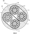
- FIG. 12 shows a cross section of a high-speed data cable 500 according to another embodiment of the present invention.
- the cores 504 are each enclosed in pairs by the conductive shield 508 and an insulating cable sheath 506 surrounds the conductive shield 508.
- each core pair 502 may be wrapped by a metal-laminated plastic film and in addition the entire bundle of wire pairs 502 of a conductive shield, for example.
- the two conductive shields 508 may have different shielding characteristics.
- the wire mesh can improve the mechanical properties, such as abrasion or bending strength of the cable.
- the wires 504 each have an insulator core 514, which is arranged along the longitudinal center axis 118 and around which ten conductors 510 with insulating coating 512 are arranged.
- the core jacket 516 in which the conductors 510 are embedded may also rest on the insulator core 514.
- Fig. 6A shows a first schematic representation of a star-four stranding.
- the conductors can be enclosed with an insulating coating. Furthermore, the conductors are surrounded by the wire jacket 616 and form a single wire 604. In the center of the wire 604, an insulating core may be arranged.
- the wires 604 may be twisted as a pair of wires 602 or star quad.
- the conductive shield 608 surrounds the cores 604 and is enclosed by the insulating sheathing 606.
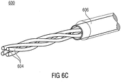
- FIG. 6B and 6C show more schematic representations of a star-four stranding.
- FIG. 6B and 6C There are four wires 604 without wire sheath. As a result, the course of the individual wires 604 in a star-quad stranding is clearly visible.
- the wires 604 are partially covered with an insulating cable sheath 606.
- the individual electrical conductors of one of the cores 604 are due to the low resolution of FIGS. 6A, 6B and 6C represented graphically as a surface.
- the embodiments shown in the figures show arrangement of electrically conductive and non-conductive elements in the cross-section of the wire 604 of the cable 600. This new arrangement reduces the attenuation down to the GHz range and also reduces the weight of the cable 600. Both will be re-used reached the usual materials.
- a wire 304 denotes the conductor or conductors 310 with insulation (insulating coating 312 and wire jacket 316).
- This disclosure describes a particular arrangement of the conductors 310 of a constant-loss attenuation-reducing core 304 with a focus on high-speed data transmission in which signal propagation times are involved. Furthermore, the structure of the high-speed data transmission cable 300 using this wire 304 will be described. The aim is a cable 300 with controlled impedance, low attenuation and small diameter.
- enamel-insulated solid conductors 310 are stranded around an insulator core 114 (nonconductive core).
- the cable 300 Due to the cable 300, with the same diameter and materials (except for the insulating coating 312 (additional paint layer) of the conductor 310 (individual wires)), a reduced damping is made possible. Also, the "top metal layer" of the conductors of a conventional wire can be replaced with paint, i. the diameter of the conductor 310 may be reduced so that the previous outer diameter of the wire 304 is obtained with the insulating coating 312. This reduces the weight per conductor. The entire outer diameter of the cable can remain the same.
- the cable 300 is particularly suitable for high-speed data transmission in the gigahertz range, where also runtime differences must be considered.
- Embodiments of the high-speed data cable can be used for symmetrical signal transmission.
- the high-speed data cable may be used, for example, in a system configured to transmit a balanced signal over the high-speed data cable.
- a system which comprises a high-speed data cable, may for example be a network with a plurality of computers or a communication network, for example for voice transmission.
- Computer here in the broadest sense includes active network nodes, at least contain a processor with memory and to which, for example, peripherals such as sensors, control units, monitors, cameras, etc. may be connected.
- aspects have been described in the context of a device, it will be understood that these aspects also constitute a description of the corresponding method, so that a block or a component of a device is also to be understood as a corresponding method step or as a feature of a method step. Similarly, aspects described in connection with or as a method step also represent a description of a corresponding block or detail or feature of a corresponding device.
- Some or all of the method steps may be performed by a hardware device (or using a hardware device). Apparatus), such as a microprocessor, a programmable computer or an electronic circuit. In some embodiments, some or more of the most important method steps may be performed by such an apparatus.
Claims (15)
- Câble de données à haut débit, comprenant:au moins une paire de fils (102; 302a, 302b; 502), où- un blindage conducteur (108; 308; 508) entoure les fils (104a, 104b; 204; 304; 404; 504; 604);- une gaine de câble isolante (106; 306; 506; 606) entoure le blindage conducteur (108; 308; 508; 608); etchacun des fils (104a, 104b; 204; 304; 404; 504; 604) comporte au moins trois conducteurs électriques (110; 210; 310; 410; 510; 610), où- chaque conducteur (110; 210; 310; 410; 510; 610) est adjacent par sa surface extérieure à au moins un matériau isolant par lequel les conducteurs (110; 210; 310; 410; 510; 610) du fil respectif (104a, 104b; 204; 304; 404; 504; 604) s'étendent séparés l'un de l'autre,caractérisé par le fait que- les conducteurs (110; 210; 310; 410; 510; 610) sont disposés de manière à s'étendre torsadés équidistants par rapport à un axe médian longitudinal (118) du fil respectif (104a, 1040b; 204; 304; 404; 504; 604).
- Câble de données à haut débit selon la revendication 1, dans lequel, dans chaque fil (204; 304; 504; 604), chaque conducteur (210; 310; 510; 610) est entouré sur sa surface extérieure d'un revêtement isolant (212; 312; 512; 612) comme matériau isolant.
- Câble de données à haut débit selon la revendication 2, dans lequel le revêtement isolant (212; 312; 512; 612) est une couche de vernis.
- Câble de données à haut débit selon la revendication 2 ou 3, dans lequel, dans chaque fil (104a, 104b; 204; 304; 404; 504; 604), les conducteurs (110, 210, 310, 410, 510, 610) sont au moins partiellement enrobés dans un matériau isolant.
- Câble de données à haut débit selon l'une quelconque des revendications précédentes, dans lequel, dans chaque fil (204; 304; 404; 504; 604), un noyau isolant (214; 314; 414; 514; 614) est disposé le long de l'axe médian longitudinal (118) auquel sont adjacents les conducteurs (210; 310; 410; 510; 610) du fil respectif (204; 304; 404; 504; 604).
- Câble de données à haut débit selon la revendication 5, dans lequel le noyau isolant (214; 314, 414; 514; 614) est réalisé en polypropylène, polyamide ou polyéthylène (chaque fois massif, en mousse ou comme mono-filament).
- Câble de données à haut débit selon la revendication 5 à 6, dans lequel, dans chaque fil (204; 304; 504; 604), les conducteurs électriques (210; 310; 510; 610) avec le revêtement isolant (212; 312; 512; 612) sont adjacents au noyau isolant (214; 314; 514; 614) ainsi qu'entre eux.
- Câble de données à haut débit selon l'une des revendications précédentes, dans lequel les fils (104; 204; 304; 404; 504; 604) s'étendent torsadés l'un contre l'autre.
- Câble de données à haut débit selon l'une des revendications précédentes, dans lequel le blindage conducteur (108; 308; 508; 608) est réalisé en un film métallique laminé de matière plastique et/ou en un treillis métallique.
- Câble de données à haut débit selon l'une des revendications précédentes, dans lequel les fils (104; 304; 504; 604) sont chaque fois entourés par paire par le blindage conducteur (108, 308, 508; 608).
- Câble de données à haut débit selon l'une des revendications précédentes, dans lequel quatre fils (304; 504; 604) sont disposés torsadés entre eux en forme de quarte en étoile.
- Câble de données à haut débit selon l'une des revendications précédentes, dans lequel chaque fil (104; 204; 304; 404; 504; 604) comporte de 3 à 18 conducteurs électriques (110; 210; 310; 410; 510; 610).
- Câble de données à haut débit selon l'une des revendications précédentes, dans lequel au moins une paire de fils (102, 302, 502, 602) présente une impédance d'onde différentielle dans la plage comprise entre 50Ω et 300Ω.
- Utilisation d'un câble de données à haut débit selon la revendication 1 pour la transmission de signal symétrique.
- Système comprenant:un câble de données à haut débit selon la revendication 1, dans lequel le système est conçu pour transmettre un signal symétrique par le câble de données à haut débit.
Applications Claiming Priority (3)
| Application Number | Priority Date | Filing Date | Title |
|---|---|---|---|
| DE102013207743 | 2013-04-26 | ||
| DE102013223584.4A DE102013223584A1 (de) | 2013-04-26 | 2013-11-19 | Hochgeschwindigkeitsdatenkabel |
| PCT/EP2014/057481 WO2014173711A1 (fr) | 2013-04-26 | 2014-04-14 | Câble de données à haut débit |
Publications (2)
| Publication Number | Publication Date |
|---|---|
| EP2989641A1 EP2989641A1 (fr) | 2016-03-02 |
| EP2989641B1 true EP2989641B1 (fr) | 2017-09-13 |
Family
ID=51685111
Family Applications (1)
| Application Number | Title | Priority Date | Filing Date |
|---|---|---|---|
| EP14720520.7A Active EP2989641B1 (fr) | 2013-04-26 | 2014-04-14 | Câble de données à haut débit |
Country Status (4)
| Country | Link |
|---|---|
| US (1) | US20160042840A1 (fr) |
| EP (1) | EP2989641B1 (fr) |
| DE (1) | DE102013223584A1 (fr) |
| WO (1) | WO2014173711A1 (fr) |
Families Citing this family (2)
| Publication number | Priority date | Publication date | Assignee | Title |
|---|---|---|---|---|
| DE102018114488A1 (de) * | 2018-06-18 | 2019-12-19 | Schaeffler Technologies AG & Co. KG | Aktor zur Betätigung einer Kraftfahrzeugkupplung mit umhülltem Kabel; sowie Kupplungssystem |
| DK201970632A1 (en) * | 2018-10-11 | 2020-05-18 | Aptiv Technologies Limited | AUTOMOTIVE COMMUNICATIONS CABLE |
Family Cites Families (10)
| Publication number | Priority date | Publication date | Assignee | Title |
|---|---|---|---|---|
| DE3150031A1 (de) * | 1981-12-17 | 1983-06-23 | H. Stoll Gmbh & Co, 7410 Reutlingen | Hochflexibles isoliertes elektrisches kabel |
| US4445321A (en) * | 1982-11-29 | 1984-05-01 | Hutchinson Raymond E | Tendon construction for posttensioning prestressed concrete and the method of making such tendons |
| GB9012062D0 (en) * | 1990-05-30 | 1990-07-18 | Phillips Cables Ltd | Moisture-impermeable stranded electric conductor |
| US6469251B1 (en) * | 2000-05-15 | 2002-10-22 | Tyco Electronics Corporation | Vapor proof high speed communications cable and method of manufacturing the same |
| FR2907256A1 (fr) * | 2006-10-11 | 2008-04-18 | Nexans Sa | Cable de controle electrique et procede de fabrication associe |
| US7674973B2 (en) * | 2008-04-18 | 2010-03-09 | George Cardas | Electrical conductor and cable utilizing same |
| KR101171554B1 (ko) * | 2008-07-31 | 2012-08-06 | 스미토모 덴키 고교 가부시키가이샤 | 차동 전송 케이블 및 그것을 포함하는 복합 케이블 |
| JP5421565B2 (ja) * | 2008-09-24 | 2014-02-19 | 住友電気工業株式会社 | 同軸ケーブル |
| JP5487661B2 (ja) * | 2009-03-19 | 2014-05-07 | ソニー株式会社 | シールドケーブル |
| US9318238B2 (en) * | 2011-10-04 | 2016-04-19 | Totoku Electric Co., Ltd. | Hollow core body for signal transmission cable |
-
2013
- 2013-11-19 DE DE102013223584.4A patent/DE102013223584A1/de not_active Withdrawn
-
2014
- 2014-04-14 WO PCT/EP2014/057481 patent/WO2014173711A1/fr active Application Filing
- 2014-04-14 EP EP14720520.7A patent/EP2989641B1/fr active Active
-
2015
- 2015-10-26 US US14/923,285 patent/US20160042840A1/en not_active Abandoned
Non-Patent Citations (1)
| Title |
|---|
| None * |
Also Published As
| Publication number | Publication date |
|---|---|
| US20160042840A1 (en) | 2016-02-11 |
| WO2014173711A1 (fr) | 2014-10-30 |
| DE102013223584A1 (de) | 2014-10-30 |
| EP2989641A1 (fr) | 2016-03-02 |
Similar Documents
| Publication | Publication Date | Title |
|---|---|---|
| DE875054C (de) | Elektrischer Leiter | |
| EP3224838B1 (fr) | Câbles à paires de fils torsadés | |
| EP3172741B1 (fr) | Câble de données pour transmissions de données à haut débit | |
| EP2697804B1 (fr) | Câble à quarte en étoile avec blindage | |
| EP3430633B1 (fr) | Câble de transmission de signaux électriques | |
| EP3132513B1 (fr) | Ensemble de câbles | |
| WO2017084835A1 (fr) | Câble de données pour transferts de données haute vitesse | |
| WO2015118025A1 (fr) | Câble de données | |
| DE102017118040A1 (de) | Zwillings-axialkabel mit erhöhter kopplung | |
| EP3285266B1 (fr) | Câble à toronnage adapté | |
| DE102014223119B4 (de) | Datenkabel sowie Verfahren zur Herstellung eines Datenkabels | |
| EP3147913B1 (fr) | Cable de transmission de donnees pouvant etre confectionne | |
| EP2989641B1 (fr) | Câble de données à haut débit | |
| WO2017076984A1 (fr) | Câble de données ainsi qu'utilisation du câble de données dans un véhicule automobile | |
| EP2697803B1 (fr) | Câble à quarte en étoile comportant un blindage | |
| EP3367514A1 (fr) | Connecteur enfichable pour applications haute fréquence, par exemple, pour application ethernet | |
| EP0568048B1 (fr) | Câble de transmission de données | |
| WO2021185983A1 (fr) | Câble | |
| DE202011004949U1 (de) | Elektrische Leitung zum Übertragen von Datensignalen | |
| DE102018103607B4 (de) | Zweidrahtleitung mit verschachtelter Isolierung, sowie Verfahren und Vorrichtung zum Herstellen einer Zweidrahtleitung | |
| WO2017072265A1 (fr) | Ligne électrique | |
| DE102014013558B4 (de) | Audiokabel zur Signalübertragung | |
| DE102020110370A1 (de) | Kabel zur elektrischen Datenübertragung | |
| DE10057289A1 (de) | Datenübertragungskabel, insbesondere USB Kabel | |
| DE102016221661A1 (de) | Kabel, insbesondere Datenkabel |
Legal Events
| Date | Code | Title | Description |
|---|---|---|---|
| PUAI | Public reference made under article 153(3) epc to a published international application that has entered the european phase |
Free format text: ORIGINAL CODE: 0009012 |
|
| 17P | Request for examination filed |
Effective date: 20151008 |
|
| AK | Designated contracting states |
Kind code of ref document: A1 Designated state(s): AL AT BE BG CH CY CZ DE DK EE ES FI FR GB GR HR HU IE IS IT LI LT LU LV MC MK MT NL NO PL PT RO RS SE SI SK SM TR |
|
| AX | Request for extension of the european patent |
Extension state: BA ME |
|
| DAX | Request for extension of the european patent (deleted) | ||
| 17Q | First examination report despatched |
Effective date: 20161128 |
|
| GRAP | Despatch of communication of intention to grant a patent |
Free format text: ORIGINAL CODE: EPIDOSNIGR1 |
|
| INTG | Intention to grant announced |
Effective date: 20170323 |
|
| GRAS | Grant fee paid |
Free format text: ORIGINAL CODE: EPIDOSNIGR3 |
|
| GRAA | (expected) grant |
Free format text: ORIGINAL CODE: 0009210 |
|
| AK | Designated contracting states |
Kind code of ref document: B1 Designated state(s): AL AT BE BG CH CY CZ DE DK EE ES FI FR GB GR HR HU IE IS IT LI LT LU LV MC MK MT NL NO PL PT RO RS SE SI SK SM TR |
|
| REG | Reference to a national code |
Ref country code: GB Ref legal event code: FG4D Free format text: NOT ENGLISH |
|
| REG | Reference to a national code |
Ref country code: CH Ref legal event code: EP |
|
| REG | Reference to a national code |
Ref country code: IE Ref legal event code: FG4D Free format text: LANGUAGE OF EP DOCUMENT: GERMAN |
|
| REG | Reference to a national code |
Ref country code: AT Ref legal event code: REF Ref document number: 928884 Country of ref document: AT Kind code of ref document: T Effective date: 20171015 |
|
| REG | Reference to a national code |
Ref country code: DE Ref legal event code: R096 Ref document number: 502014005444 Country of ref document: DE |
|
| REG | Reference to a national code |
Ref country code: NL Ref legal event code: MP Effective date: 20170913 |
|
| REG | Reference to a national code |
Ref country code: LT Ref legal event code: MG4D |
|
| PG25 | Lapsed in a contracting state [announced via postgrant information from national office to epo] |
Ref country code: HR Free format text: LAPSE BECAUSE OF FAILURE TO SUBMIT A TRANSLATION OF THE DESCRIPTION OR TO PAY THE FEE WITHIN THE PRESCRIBED TIME-LIMIT Effective date: 20170913 Ref country code: NO Free format text: LAPSE BECAUSE OF FAILURE TO SUBMIT A TRANSLATION OF THE DESCRIPTION OR TO PAY THE FEE WITHIN THE PRESCRIBED TIME-LIMIT Effective date: 20171213 Ref country code: LT Free format text: LAPSE BECAUSE OF FAILURE TO SUBMIT A TRANSLATION OF THE DESCRIPTION OR TO PAY THE FEE WITHIN THE PRESCRIBED TIME-LIMIT Effective date: 20170913 Ref country code: SE Free format text: LAPSE BECAUSE OF FAILURE TO SUBMIT A TRANSLATION OF THE DESCRIPTION OR TO PAY THE FEE WITHIN THE PRESCRIBED TIME-LIMIT Effective date: 20170913 Ref country code: FI Free format text: LAPSE BECAUSE OF FAILURE TO SUBMIT A TRANSLATION OF THE DESCRIPTION OR TO PAY THE FEE WITHIN THE PRESCRIBED TIME-LIMIT Effective date: 20170913 |
|
| PG25 | Lapsed in a contracting state [announced via postgrant information from national office to epo] |
Ref country code: LV Free format text: LAPSE BECAUSE OF FAILURE TO SUBMIT A TRANSLATION OF THE DESCRIPTION OR TO PAY THE FEE WITHIN THE PRESCRIBED TIME-LIMIT Effective date: 20170913 Ref country code: BG Free format text: LAPSE BECAUSE OF FAILURE TO SUBMIT A TRANSLATION OF THE DESCRIPTION OR TO PAY THE FEE WITHIN THE PRESCRIBED TIME-LIMIT Effective date: 20171213 Ref country code: ES Free format text: LAPSE BECAUSE OF FAILURE TO SUBMIT A TRANSLATION OF THE DESCRIPTION OR TO PAY THE FEE WITHIN THE PRESCRIBED TIME-LIMIT Effective date: 20170913 Ref country code: GR Free format text: LAPSE BECAUSE OF FAILURE TO SUBMIT A TRANSLATION OF THE DESCRIPTION OR TO PAY THE FEE WITHIN THE PRESCRIBED TIME-LIMIT Effective date: 20171214 Ref country code: RS Free format text: LAPSE BECAUSE OF FAILURE TO SUBMIT A TRANSLATION OF THE DESCRIPTION OR TO PAY THE FEE WITHIN THE PRESCRIBED TIME-LIMIT Effective date: 20170913 |
|
| PG25 | Lapsed in a contracting state [announced via postgrant information from national office to epo] |
Ref country code: NL Free format text: LAPSE BECAUSE OF FAILURE TO SUBMIT A TRANSLATION OF THE DESCRIPTION OR TO PAY THE FEE WITHIN THE PRESCRIBED TIME-LIMIT Effective date: 20170913 |
|
| REG | Reference to a national code |
Ref country code: FR Ref legal event code: PLFP Year of fee payment: 5 |
|
| PG25 | Lapsed in a contracting state [announced via postgrant information from national office to epo] |
Ref country code: CZ Free format text: LAPSE BECAUSE OF FAILURE TO SUBMIT A TRANSLATION OF THE DESCRIPTION OR TO PAY THE FEE WITHIN THE PRESCRIBED TIME-LIMIT Effective date: 20170913 Ref country code: PL Free format text: LAPSE BECAUSE OF FAILURE TO SUBMIT A TRANSLATION OF THE DESCRIPTION OR TO PAY THE FEE WITHIN THE PRESCRIBED TIME-LIMIT Effective date: 20170913 Ref country code: RO Free format text: LAPSE BECAUSE OF FAILURE TO SUBMIT A TRANSLATION OF THE DESCRIPTION OR TO PAY THE FEE WITHIN THE PRESCRIBED TIME-LIMIT Effective date: 20170913 |
|
| PG25 | Lapsed in a contracting state [announced via postgrant information from national office to epo] |
Ref country code: SM Free format text: LAPSE BECAUSE OF FAILURE TO SUBMIT A TRANSLATION OF THE DESCRIPTION OR TO PAY THE FEE WITHIN THE PRESCRIBED TIME-LIMIT Effective date: 20170913 Ref country code: SK Free format text: LAPSE BECAUSE OF FAILURE TO SUBMIT A TRANSLATION OF THE DESCRIPTION OR TO PAY THE FEE WITHIN THE PRESCRIBED TIME-LIMIT Effective date: 20170913 Ref country code: IS Free format text: LAPSE BECAUSE OF FAILURE TO SUBMIT A TRANSLATION OF THE DESCRIPTION OR TO PAY THE FEE WITHIN THE PRESCRIBED TIME-LIMIT Effective date: 20180113 Ref country code: EE Free format text: LAPSE BECAUSE OF FAILURE TO SUBMIT A TRANSLATION OF THE DESCRIPTION OR TO PAY THE FEE WITHIN THE PRESCRIBED TIME-LIMIT Effective date: 20170913 Ref country code: IT Free format text: LAPSE BECAUSE OF FAILURE TO SUBMIT A TRANSLATION OF THE DESCRIPTION OR TO PAY THE FEE WITHIN THE PRESCRIBED TIME-LIMIT Effective date: 20170913 |
|
| REG | Reference to a national code |
Ref country code: DE Ref legal event code: R097 Ref document number: 502014005444 Country of ref document: DE |
|
| PLBE | No opposition filed within time limit |
Free format text: ORIGINAL CODE: 0009261 |
|
| STAA | Information on the status of an ep patent application or granted ep patent |
Free format text: STATUS: NO OPPOSITION FILED WITHIN TIME LIMIT |
|
| PG25 | Lapsed in a contracting state [announced via postgrant information from national office to epo] |
Ref country code: DK Free format text: LAPSE BECAUSE OF FAILURE TO SUBMIT A TRANSLATION OF THE DESCRIPTION OR TO PAY THE FEE WITHIN THE PRESCRIBED TIME-LIMIT Effective date: 20170913 |
|
| 26N | No opposition filed |
Effective date: 20180614 |
|
| PG25 | Lapsed in a contracting state [announced via postgrant information from national office to epo] |
Ref country code: MT Free format text: LAPSE BECAUSE OF FAILURE TO SUBMIT A TRANSLATION OF THE DESCRIPTION OR TO PAY THE FEE WITHIN THE PRESCRIBED TIME-LIMIT Effective date: 20170913 |
|
| PG25 | Lapsed in a contracting state [announced via postgrant information from national office to epo] |
Ref country code: MC Free format text: LAPSE BECAUSE OF FAILURE TO SUBMIT A TRANSLATION OF THE DESCRIPTION OR TO PAY THE FEE WITHIN THE PRESCRIBED TIME-LIMIT Effective date: 20170913 Ref country code: SI Free format text: LAPSE BECAUSE OF FAILURE TO SUBMIT A TRANSLATION OF THE DESCRIPTION OR TO PAY THE FEE WITHIN THE PRESCRIBED TIME-LIMIT Effective date: 20170913 |
|
| REG | Reference to a national code |
Ref country code: CH Ref legal event code: PL |
|
| REG | Reference to a national code |
Ref country code: BE Ref legal event code: MM Effective date: 20180430 |
|
| REG | Reference to a national code |
Ref country code: IE Ref legal event code: MM4A |
|
| PG25 | Lapsed in a contracting state [announced via postgrant information from national office to epo] |
Ref country code: LU Free format text: LAPSE BECAUSE OF NON-PAYMENT OF DUE FEES Effective date: 20180414 |
|
| PG25 | Lapsed in a contracting state [announced via postgrant information from national office to epo] |
Ref country code: LI Free format text: LAPSE BECAUSE OF NON-PAYMENT OF DUE FEES Effective date: 20180430 Ref country code: BE Free format text: LAPSE BECAUSE OF NON-PAYMENT OF DUE FEES Effective date: 20180430 Ref country code: CH Free format text: LAPSE BECAUSE OF NON-PAYMENT OF DUE FEES Effective date: 20180430 |
|
| PG25 | Lapsed in a contracting state [announced via postgrant information from national office to epo] |
Ref country code: IE Free format text: LAPSE BECAUSE OF NON-PAYMENT OF DUE FEES Effective date: 20180414 |
|
| PG25 | Lapsed in a contracting state [announced via postgrant information from national office to epo] |
Ref country code: TR Free format text: LAPSE BECAUSE OF FAILURE TO SUBMIT A TRANSLATION OF THE DESCRIPTION OR TO PAY THE FEE WITHIN THE PRESCRIBED TIME-LIMIT Effective date: 20170913 |
|
| PG25 | Lapsed in a contracting state [announced via postgrant information from national office to epo] |
Ref country code: PT Free format text: LAPSE BECAUSE OF FAILURE TO SUBMIT A TRANSLATION OF THE DESCRIPTION OR TO PAY THE FEE WITHIN THE PRESCRIBED TIME-LIMIT Effective date: 20170913 |
|
| PG25 | Lapsed in a contracting state [announced via postgrant information from national office to epo] |
Ref country code: HU Free format text: LAPSE BECAUSE OF FAILURE TO SUBMIT A TRANSLATION OF THE DESCRIPTION OR TO PAY THE FEE WITHIN THE PRESCRIBED TIME-LIMIT; INVALID AB INITIO Effective date: 20140414 Ref country code: MK Free format text: LAPSE BECAUSE OF NON-PAYMENT OF DUE FEES Effective date: 20170913 Ref country code: CY Free format text: LAPSE BECAUSE OF FAILURE TO SUBMIT A TRANSLATION OF THE DESCRIPTION OR TO PAY THE FEE WITHIN THE PRESCRIBED TIME-LIMIT Effective date: 20170913 |
|
| PG25 | Lapsed in a contracting state [announced via postgrant information from national office to epo] |
Ref country code: AL Free format text: LAPSE BECAUSE OF FAILURE TO SUBMIT A TRANSLATION OF THE DESCRIPTION OR TO PAY THE FEE WITHIN THE PRESCRIBED TIME-LIMIT Effective date: 20170913 |
|
| REG | Reference to a national code |
Ref country code: AT Ref legal event code: MM01 Ref document number: 928884 Country of ref document: AT Kind code of ref document: T Effective date: 20190414 |
|
| PG25 | Lapsed in a contracting state [announced via postgrant information from national office to epo] |
Ref country code: AT Free format text: LAPSE BECAUSE OF NON-PAYMENT OF DUE FEES Effective date: 20190414 |
|
| P01 | Opt-out of the competence of the unified patent court (upc) registered |
Effective date: 20230524 |
|
| PGFP | Annual fee paid to national office [announced via postgrant information from national office to epo] |
Ref country code: FR Payment date: 20230417 Year of fee payment: 10 Ref country code: DE Payment date: 20230418 Year of fee payment: 10 |
|
| PGFP | Annual fee paid to national office [announced via postgrant information from national office to epo] |
Ref country code: GB Payment date: 20230420 Year of fee payment: 10 |