EP2989380B1 - Led-leuchte mit lichtleiterplatte - Google Patents
Led-leuchte mit lichtleiterplatte Download PDFInfo
- Publication number
- EP2989380B1 EP2989380B1 EP14719266.0A EP14719266A EP2989380B1 EP 2989380 B1 EP2989380 B1 EP 2989380B1 EP 14719266 A EP14719266 A EP 14719266A EP 2989380 B1 EP2989380 B1 EP 2989380B1
- Authority
- EP
- European Patent Office
- Prior art keywords
- light source
- led light
- carrier element
- led
- guiding panel
- Prior art date
- Legal status (The legal status is an assumption and is not a legal conclusion. Google has not performed a legal analysis and makes no representation as to the accuracy of the status listed.)
- Active
Links
Images


Classifications
-
- G—PHYSICS
- G02—OPTICS
- G02B—OPTICAL ELEMENTS, SYSTEMS OR APPARATUS
- G02B6/00—Light guides; Structural details of arrangements comprising light guides and other optical elements, e.g. couplings
- G02B6/0001—Light guides; Structural details of arrangements comprising light guides and other optical elements, e.g. couplings specially adapted for lighting devices or systems
- G02B6/0011—Light guides; Structural details of arrangements comprising light guides and other optical elements, e.g. couplings specially adapted for lighting devices or systems the light guides being planar or of plate-like form
- G02B6/0081—Mechanical or electrical aspects of the light guide and light source in the lighting device peculiar to the adaptation to planar light guides, e.g. concerning packaging
- G02B6/0086—Positioning aspects
- G02B6/0091—Positioning aspects of the light source relative to the light guide
-
- G—PHYSICS
- G02—OPTICS
- G02B—OPTICAL ELEMENTS, SYSTEMS OR APPARATUS
- G02B6/00—Light guides; Structural details of arrangements comprising light guides and other optical elements, e.g. couplings
- G02B6/0001—Light guides; Structural details of arrangements comprising light guides and other optical elements, e.g. couplings specially adapted for lighting devices or systems
- G02B6/0011—Light guides; Structural details of arrangements comprising light guides and other optical elements, e.g. couplings specially adapted for lighting devices or systems the light guides being planar or of plate-like form
- G02B6/0066—Light guides; Structural details of arrangements comprising light guides and other optical elements, e.g. couplings specially adapted for lighting devices or systems the light guides being planar or of plate-like form characterised by the light source being coupled to the light guide
- G02B6/0073—Light emitting diode [LED]
-
- G—PHYSICS
- G02—OPTICS
- G02B—OPTICAL ELEMENTS, SYSTEMS OR APPARATUS
- G02B6/00—Light guides; Structural details of arrangements comprising light guides and other optical elements, e.g. couplings
- G02B6/0001—Light guides; Structural details of arrangements comprising light guides and other optical elements, e.g. couplings specially adapted for lighting devices or systems
- G02B6/0011—Light guides; Structural details of arrangements comprising light guides and other optical elements, e.g. couplings specially adapted for lighting devices or systems the light guides being planar or of plate-like form
- G02B6/0013—Means for improving the coupling-in of light from the light source into the light guide
- G02B6/0023—Means for improving the coupling-in of light from the light source into the light guide provided by one optical element, or plurality thereof, placed between the light guide and the light source, or around the light source
- G02B6/0025—Diffusing sheet or layer; Prismatic sheet or layer
-
- G—PHYSICS
- G02—OPTICS
- G02B—OPTICAL ELEMENTS, SYSTEMS OR APPARATUS
- G02B6/00—Light guides; Structural details of arrangements comprising light guides and other optical elements, e.g. couplings
- G02B6/0001—Light guides; Structural details of arrangements comprising light guides and other optical elements, e.g. couplings specially adapted for lighting devices or systems
- G02B6/0011—Light guides; Structural details of arrangements comprising light guides and other optical elements, e.g. couplings specially adapted for lighting devices or systems the light guides being planar or of plate-like form
- G02B6/0033—Means for improving the coupling-out of light from the light guide
- G02B6/005—Means for improving the coupling-out of light from the light guide provided by one optical element, or plurality thereof, placed on the light output side of the light guide
- G02B6/0055—Reflecting element, sheet or layer
-
- G—PHYSICS
- G02—OPTICS
- G02B—OPTICAL ELEMENTS, SYSTEMS OR APPARATUS
- G02B6/00—Light guides; Structural details of arrangements comprising light guides and other optical elements, e.g. couplings
- G02B6/0001—Light guides; Structural details of arrangements comprising light guides and other optical elements, e.g. couplings specially adapted for lighting devices or systems
- G02B6/0011—Light guides; Structural details of arrangements comprising light guides and other optical elements, e.g. couplings specially adapted for lighting devices or systems the light guides being planar or of plate-like form
- G02B6/0066—Light guides; Structural details of arrangements comprising light guides and other optical elements, e.g. couplings specially adapted for lighting devices or systems the light guides being planar or of plate-like form characterised by the light source being coupled to the light guide
- G02B6/0068—Arrangements of plural sources, e.g. multi-colour light sources
Definitions
- the invention relates to a luminaire with an LED light source (LED: light emitting diode) and a light guide plate.
- LED light source
- the LED light source In such a luminaire, the LED light source must be positioned accurately relative to the light guide plate during assembly, so that proper operation of the light of the LED light source is ensured in the light guide during operation of the lamp. In order to achieve a particularly effective coupling or irradiation of the light a particularly precise positioning is required. This is associated with considerable effort in practice.
- a backlight unit having an LED light source and a light guide plate is known.
- a receiving element To support the light guide plate is a receiving element.
- the LED light source is connected via a spring element with the receiving element.
- a lighting unit with an LED light source and a light guide plate is known.
- To support the light guide plate is a back plate.
- An LED light source support member is slidably disposed opposite the back plate.
- the invention has for its object to provide a corresponding improved luminaire;
- the luminaire should enable a simplified assembly with high efficiency.
- a luminaire which has an LED light source for generating a light, and a light guide plate, wherein the LED light source is arranged such that the light is coupled into the light guide plate.
- the LED light source is arranged such that the light generated by the LED light source is irradiated via a Einstrahl-edge surface of the light guide plate in the light guide plate.
- the lamp has a support element for supporting the light guide plate, and an LED light source support element, wherein the LED light source support member is slidably mounted relative to the support element.
- This design can be advantageously achieved that can bring the light guide plate initially using the support member in a certain reference plane for assembly of the lamp and then provided by a simple displacement of the LED light source support member intended for operation of the lamp Relative positioning between the LED light source and the light guide is made. In this way, the assembly of the lamp is facilitated.
- the LED light source carrier element is slidably mounted relative to the support element such that it can be displaced from a mounting position to an operating position, wherein the light guide plate can be reversibly separated from the rest of the light when the LED light source support member in the Mounting position is located.
- the light guide plate can be particularly easy to arrange on the support element when assembling the lamp when the LED light source support member is in the mounting position.
- the light guide plate is held relative to the LED light source by the LED light source support member in a position provided for operation of the lamp when the LED light source support member is in the operative position.
- the light guide plate is particularly suitably fixed securely positioned when the LED light source support member is in the operating position.
- the light guide plate is supported relative to the LED light source by the LED light source support member in a position provided for operation of the lamp when the LED light source support member is in the operative position.
- the lamp is designed such that the LED light source carrier element presses in the operating position laterally against the light guide plate.
- the LED light source carrier element presses in the operating position laterally against the light guide plate.
- the LED light source carrier element is positioned in the operating position by means of a spring element in an engaged position relative to the support element. This makes it possible to achieve a more secure fixation of the relative position during operation of the lamp; In addition, it is thereby advantageously haptically detectable during assembly of the lamp when the LED light source carrier element has reached the operating position at the end of the displacement.
- the LED light source carrier element is shaped such that in the operating position it engages around the light guide plate in a positioning manner. This allows a particularly reliable and secure mounting or securing the position of the light guide plate.
- the LED light source carrier element preferably has a carrier plate. As a result, the displaceability of the LED light source carrier element relative to the support element can be effected in a particularly suitable manner.
- the carrier plate is angled. This makes it particularly suitable to achieve that changes in the size of the light guide plate caused by fluctuations in temperature are absorbed or compensated by the LED light source support element.
- the carrier sheet is made of aluminum. This makes it possible to achieve that the support plate has a particularly suitable flexibility. In addition, this advantageously heat, which is produced during operation of the LED light source, are derived via the LED light source carrier element.
- the LED light source carrier element preferably has a light exit diffuser, which influences the light of the LED light source diffusely. This makes it possible to achieve that the light of the LED light source is coupled particularly uniformly into the light guide plate, in particular if the LED light source has a plurality of LEDs.
- the light exit diffuser is arranged connected via a latching connection with the remaining LED light source carrier element.
- the assembly of the LED light source support member is facilitated.
- the light exit diffuser abuts against the light guide plate. This makes it possible to achieve that the LED light source is particularly suitably arranged in a defined position, in particular at a defined distance from the light guide plate.
- the LED light source has a plurality of LEDs
- the light exit diffuser has a plurality of holes, each of the LEDs being accurately engaged in one of the holes. This makes it possible to achieve that the light exit diffuser affects the light of the LED light source particularly effectively and suitably.
- a reflector is arranged between the light guide plate and the support element. In this way it can be achieved that a lot of light is emitted from the light guide plate and thus the efficiency of the light is increased.
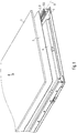
- Fig. 1 shows a perspective sketch of parts of a lamp according to the invention.
- the lamp has an LED light source 2 for generating a light, and a light guide plate 3. Due to the plate shape, the light guide plate 3 on two opposite sides on two major main surfaces, the small or narrow edge surfaces, so to speak frontal surfaces with each other are connected.
- FIG. 1 shown sketch is a representation in the manner of an exploded view.
- the LED light source 2 when the light is assembled as intended, arranged such that the light generated by the LED light source 2 via one of the edge surfaces of the light guide plate 3, hereinafter also referred to as "Einstrahl-edge surface" in the light guide plate 3 is coupled or irradiated.
- the light thus coupled into the light guide plate 3 is emitted via at least one of the two major main surfaces.
- the light is thus emitted "surface" over the light guide plate 3.
- the radiation takes place over that main surface facing in the direction indicated by an arrow R direction.
- the luminaire is oriented so that the light guide plate 3 is oriented horizontally and the direction R is vertically upward.
- this orientation is not limitative and is chosen only for the purpose of this description.
- the luminaire may be a ceiling luminaire which is provided for a light emission of the light guide plate downwards.
- the lamp has a support element 4, which serves to support the light guide plate 3.
- the support element 4 may, for example, advantageously be a sheet metal part in terms of manufacturing technology.
- the support element 4 can total - as from Fig. 1 by way of example - be designed substantially plate-shaped, wherein the support element 4 is aligned parallel to the light guide plate 3.
- the lamp has an LED light source carrier element 5.
- Fig. 2 is an end portion of the LED light source support member 5, connected to the LED light source 2 separated from the rest of the light sketched in perspective.
- the LED light source 2 may comprise a board on which a plurality of LEDs 21 are arranged, in particular arranged along a horizontal straight line G.
- the LED light source carrier element 5 is arranged displaceably mounted relative to the support element 4.
- the storage can be advantageously designed manufacturing technology as a sliding bearing.
- the LED light source carrier element 5 with the support element 4 is correspondingly movable connected.
- the support element 4 serves as a holder for the LED light source carrier element.
- the LED light source carrier element 5 is arranged displaceably relative to the support element 4 such that it can be displaced from a mounting position into an operating position, wherein the light guide plate 3 can be reversibly separated from the remaining light when the LED light source Carrier element 5 is located in the mounting position.
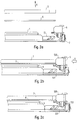
- FIGs 2a, 2b and 2c three cross-sectional views are shown to these two positions of the LED light source support member 5.
- the LED light source support member 5 is in the mounting position.
- the light guide plate 3 can be removed in the direction R or up without obstruction or the other hand approaching obstacle-free from above against the direction R, ie down or on the support element 4 move until it is in the intended position for operation relative to the support element 4.
- the LED light source carrier element 5 can thus advantageously be arranged in the mounting position and subsequently the light guide plate 3 can be moved from the top downward toward the direction R.
- the LED light source carrier element 5 is in the operating position. In this situation, the light guide plate 3 is held relative to the LED light source 2 by the LED light source support member 5 in a position provided for operation of the lamp.
- the LED light source carrier element 5 is arranged displaceably mounted such that moves by moving from the mounting position to the operating position, the LED light source 2 and the row of LEDs 21 to the Einstrahl-edge surface of the light guide plate 3.
- the storage is accordingly such that during the movement, the LED light source 2 moves horizontally and at right angles to the straight line G.
- this displacement direction V is indicated by a thick arrow.
- Fig. 13 is a perspective sectional view showing a situation in which the LED light source support member 5 is in the operative position.
- the LEDs 21 are in this situation preferably very close to the light guide plate 3 and its Einstrahl-edge surface, so that a particularly efficient coupling of the light is possible.
- the LED light source carrier element 5 is shaped such that in the operating position it engages around the light guide plate 3 in a positioning manner.
- the LED light source support member 5 for this projections or arms 55 which serve to fix the position of the light guide plate 3 and in particular the light guide plate 3 from above and below embrace. This allows a particularly reliable and secure positioning of the light guide plate 3.
- the lamp is designed so that the LED light source carrier element 5 presses in the operating position laterally against the light guide plate 3.
- the LED light source carrier element 5 presses in the operating position laterally against the light guide plate 3.
- the LED light source carrier element 5 preferably has a carrier plate 53.
- a mechanically particularly advantageous embodiment is made possible when the support plate 53 is executed angled, in particular angled around an edge which extends parallel to the straight line G. In this way, a horizontal leg 531 of the support plate 53 and a vertical leg 532 of the support plate 53 are formed. As a result, a resilient pressing of the LED light source 2 against the light guide plate 3 is particularly advantageous.
- the support plate 53 is made of aluminum. This is advantageous not only with respect to the mentioned pressing, but also allows a particularly suitable dissipation of heat, which may arise during operation of the LED light source 2.
- the LED light source carrier element 5 is positioned in the operating position with the aid of a spring element 7, positioned relative to the support element 4.
- a spring element 7 positioned relative to the support element 4.
- the spring element 7 is fitted from below onto the support element 4 for assembly, wherein it with a spring extension 71 a - in Fig. 4 designated - passes through hole 41 in the support element 4 and into a - in Fig. 3 designated - recess 57 of the LED light source support member 5 engages when the LED light source support member 5 is in the operating position.
- the recess 57 is formed on the horizontal leg 531 of the support plate 53.
- the spring element 7 further comprises guide arms 72, which serve for guiding during the displacement movement of the LED light source carrier element 5 from the mounting position into the operating position.
- the support element 4 preferably has corresponding further passage holes 42 for this purpose.
- the carrier element 53 can in this case - as in Fig. 3 shown - slots 59, into which the guide arms 72 of the spring element 7 engage accordingly.
- these slots 59 are formed on the horizontal leg 531 of the support plate 53.
- the support plate 53 further - with respect to the straight line G - at the two end portions stops 535, which serve to further position securing the light guide plate 3.
- the stops 535 may be formed, for example, by bent regions of the vertical leg 532 of the carrier plate 53.
- the LED light source support member 5 preferably has one in which Figures 3 and 4 designated, Lichtaustrittsdiffusor 51, which is designed so that it receives the light of the LED light source 2 influenced diffusely.
- Lichtausbergsdiffusor 51 which is designed so that it receives the light of the LED light source 2 influenced diffusely.
- the light exit diffuser 51 is preferably arranged via a latching connection with the remaining LED light source carrier element 5, in particular with the carrier plate 53. As a result, a particularly simple assembly of the LED light source carrier element 5 is made possible.
- the LED light source 2 is arranged supported by the light exit diffuser 51 on the remaining LED light source carrier element 5, in particular on the carrier plate 53.
- the light exit diffuser 51 preferably has a plurality of holes 52, each of the LEDs 21 being arranged exactly in one of the holes 52.
- a particularly good protection of the LEDs 21 and, on the other hand, a particularly precise relative positioning of the LEDs 21 with respect to the light guide plate 3 is made possible by this design.
- the LED light source 2 is preferably supported between the support plate 52 on the one hand and the light exit diffuser 53 on the other.
- the LEDs 21 are arranged on one side of the board of the LED light source 2 and the light exit diffuser 51 is applied to this board, on the side on which the LEDs 21 are located.
- the light exit diffuser 51 surrounds the LEDs 21 with its holes 52.
- the light exit diffuser 51 may have pins which pass through openings in the board and form the above-mentioned latching connection on the opposite side to the carrier element 53.
- the light exit diffuser 51 it can be achieved by the light exit diffuser 51 that the LEDs 21 are particularly well protected during the assembly of the luminaire.
- the light exit diffuser 51 is made of polycarbonate (PC).
- the luminaire is designed such that the light exit diffuser 51 rests against the light guide plate 3 or at its incident edge face when the LED light source support element 5 is in the operating position.
- This makes it possible to achieve that a suitable relative position, in particular a specific distance between the light guide plate 3 and the LED light source 2, is maintained particularly reliably during the operation of the luminaire.
- the lamp further comprises a reflector 6; This can increase the efficiency of the radiation of the lamp.
- the reflector 6 is preferably plate-shaped and arranged parallel to the light guide plate 3, between the light guide plate 3 and the support element 4. In the example shown surrounds the LED light source support member 5 with the arms 55 laterally both the light guide plate 3, and the reflector 6.
- the stops 535 of the support member 53 are designed so that they also act in accordance Sagesichemd on the reflector 6.
- the LED light source 2 with the light exit diffuser 51 is mounted on the support plate 53.
- an "LED unit” is formed.
- the LED unit is connected by means of the spring element 7 with the support element 4, in such a way that the LED light source support element 5, so the Lichtaustrittsdiffusor 51 and the support plate 53 are in the mounting position.
- the LED unit or the LED light source carrier element 5 is moved to the operating position, that is displaced so far until the spring extension 71 of the spring element 7 engages in the recess 57 of the LED light source carrier element 5.
- the printed circuit board 3 is held fixed relative to the LED light source 2 in the relative position provided for the operation of the luminaire.
- the LED light source 5 is protected during assembly, and in operation, the "LED dots" are resolved by the light exit diffuser 51.
- the arrangement according to the invention can be achieved that the light guide plate 3 and optionally the reflector 6 can be easily attached and the LED light source 2 can be positioned particularly suitable and reliable relative to the light guide plate 3.
- Fig. 1 an embodiment is shown in which the lamp also has a further LED unit, which is designed analogous to the first-mentioned LED unit, the design being such that the further LED unit their light via a further Einstrahl-edge surface of the Light guide plate 3 irradiates in the latter, which is opposite to the first-mentioned Einstrahl-edge surface.
Landscapes
- Physics & Mathematics (AREA)
- General Physics & Mathematics (AREA)
- Optics & Photonics (AREA)
- Engineering & Computer Science (AREA)
- Microelectronics & Electronic Packaging (AREA)
- Planar Illumination Modules (AREA)
- Arrangements Of Lighting Devices For Vehicle Interiors, Mounting And Supporting Thereof, Circuits Therefore (AREA)
- Illuminated Signs And Luminous Advertising (AREA)
Description
- Die Erfindung betrifft eine Leuchte mit einer LED-Lichtquelle (LED: Licht emittierende Diode) und einer Lichtleiterplatte.
- Bei einer derartigen Leuchte muss beim Zusammenbau die LED-Lichtquelle relativ zu der Lichtleiterplatte genau positioniert werden, damit bei Betrieb der Leuchte eine einwandfreie Einkopplung des Lichts der LED-Lichtquelle in den Lichtleiter sichergestellt ist. Zur Erzielung einer besonders effektiven Einkopplung bzw. Einstrahlung des Lichts ist dabei eine besonders präzise Positionierung erforderlich. Dies ist in der Praxis mit erheblichem Aufwand verbunden.
- Aus der
EP 2 192 430 A2 ist eine Hintergrundbeleuchtungseinheit mit einer LED-Lichtquelle und einer Lichtleiterplatte bekannt. Zur Auflage der Lichtleiterplatte dient ein Aufnahmeelement. Die LED-Lichtquelle ist über ein Federelement mit dem Aufnahmeelement verbunden. - Aus der
CN 102 537 884 A ist eine Beleuchtungseinheit mit einer LED-Lichtquelle und einer Lichtleiterplatte bekannt. Zur Auflage der Lichtleiterplatte dient eine Rückplatte. Ein LED-Lichtquellen-Trägerelement ist verschiebbar gegenüber der Rückplatte angeordnet. - Der Erfindung liegt die Aufgabe zugrunde, eine entsprechende verbesserte Leuchte anzugeben; insbesondere soll die Leuchte bei hoher Effizienz einen erleichterten Zusammenbau ermöglichen.
- Diese Aufgabe wird gemäß der Erfindung mit dem in dem unabhängigen Anspruch genannten Gegenstand gelöst. Besondere Ausführungsformen der Erfindung sind in den abhängigen Ansprüchen angegeben.
- Gemäß der Erfindung ist eine Leuchte vorgesehen, die eine LED-Lichtquelle zur Erzeugung eines Lichts aufweist, sowie eine Lichtleiterplatte, wobei die LED-Lichtquelle derart angeordnet ist, dass das Licht in die Lichtleiterplatte eingekoppelt wird. Die LED-Lichtquelle ist dabei derart angeordnet, dass das von der der LED-Lichtquelle erzeugte Licht über eine Einstrahl-Randfläche der Lichtleiterplatte in die Lichtleiterplatte eingestrahlt wird. Außerdem weist die Leuchte ein Auflageelement zur Auflage der Lichtleiterplatte auf, sowie ein LED-Lichtquellen-Trägerelement, wobei das LED-Lichtquellen-Trägerelement verschiebbar relativ zu dem Auflageelement gelagert angeordnet ist.
- Durch diese Gestaltung lässt sich vorteilhaft erzielen, dass sich zum Zusammenbau der Leuchte die Lichtleiterplatte zunächst mithilfe des Auflageelements in eine bestimmte Bezugsebene bringen lässt und anschließend durch ein einfaches Verschieben des LED-Lichtquellen-Trägerelements die für einen Betrieb der Leuchte vorgesehene Relativpositionierung zwischen der LED-Lichtquelle und dem Lichtleiter hergestellt wird. Auf diese Weise ist der Zusammenbau der Leuchte erleichtert.
- Erfindungsgemäß ist das LED-Lichtquellen-Trägerelement derart verschiebbar relativ zu dem Auflageelement gelagert angeordnet, dass es von einer Montageposition in eine Betriebsposition verschiebbar ist, wobei die Lichtleiterplatte reversibel von der restlichen Leuchte separiert werden kann, wenn sich das LED-Lichtquellen-Trägerelement in der Montageposition befindet. Auf diese Weise lässt sich die Lichtleiterplatte beim Zusammenbau der Leuchte besonders einfach auf dem Auflageelement wie vorgesehen anordnen, wenn sich das LED-Lichtquellen-Trägerelement in der Montageposition befindet.
- Erfindungsgemäß ist die Lichtleiterplatte relativ zu der LED-Lichtquelle durch das LED-Lichtquellen-Trägerelement in einer für einen Betrieb der Leuchte vorgesehenen Stellung gehaltert, wenn sich das LED-Lichtquellen-Trägerelement in der Betriebsposition befindet. Auf diese Weise lässt sich erzielen, dass die Lichtleiterplatte besonders geeignet sicher positioniert fixiert ist, wenn sich das LED-Lichtquellen-Trägerelement in der Betriebsposition befindet.
- Die Lichtleiterplatte ist relativ zu der LED-Lichtquelle durch das LED-Lichtquellen-Trägerelement in einer für einen Betrieb der Leuchte vorgesehenen Stellung gehaltert, wenn sich das LED-Lichtquellen-Trägerelement in der Betriebsposition befindet.
- Vorzugsweise ist die Leuchte derart gestaltet, dass das LED-Lichtquellen-Trägerelement in der Betriebsposition seitlich gegen die Lichtleiterplatte drückt. Auf diese Weise lässt sich sicherstellen, dass die geeignete Relativposition zwischen der Lichtleiterplatte und der LED-Lichtquelle im Verlauf eines Betriebs der Leuchte zuverlässig beibehalten wird, insbesondere auch bei entsprechenden Temperaturschwankungen und den damit verbundenen Größenveränderungen der Bauteile der Leuchte, also beispielsweise, wenn sich die Lichtleiterplatte und das Auflageelement unterschiedlich stark ausdehnen.
- Erfindungsgemäß ist das LED-Lichtquellen-Trägerelement in der Betriebsposition mithilfe eines Federelements eingerastet positioniert relativ zu dem Auflageelement angeordnet. Hierdurch lässt sich eine weitergehende sichere Fixierung der Relativposition bei Betrieb der Leuchte erzielen; außerdem ist es hierdurch beim Zusammenbau der Leuchte vorteilhaft haptisch erfassbar, wenn am Ende des Verschiebens das LED-Lichtquellen-Trägerelement die Betriebsposition erreicht hat.
- Vorzugsweise ist das LED-Lichtquellen-Trägerelement derart geformt, dass es in der Betriebsposition die Lichtleiterplatte positionierend umgreift. Hierdurch ist eine besonders zuverlässige und sichere Halterung bzw. Lagesicherung der Lichtleiterplatte ermöglicht.
- Vorzugsweise weist das LED-Lichtquellen-Trägerelement ein Trägerblech auf. Hierdurch lässt sich besonders geeignet die Verschiebbarkeit des LED-Lichtquellen-Trägerelements relativ zu dem Auflageelement bewirken.
- Weiterhin vorzugsweise ist dabei das Trägerblech abgewinkelt geformt. Hierdurch lässt sich besonders geeignet erzielen, dass temperaturschwankungsbedingte Größenänderungen der Lichtleiterplatte durch das LED-Lichtquellen-Trägerelement aufgefangen bzw. ausgeglichen werden.
- Weiterhin vorzugsweise besteht das Trägerblech aus Aluminium. Hierdurch lässt sich erzielen, dass das Trägerblech eine besonders geeignete Flexibilität aufweist. Zudem kann hierdurch vorteilhaft Wärme, die bei einem Betrieb der LED-Lichtquelle entsteht, über das LED-Lichtquellen-Trägerelement abgleitet werden.
- Vorzugsweise weist das LED-Lichtquellen-Trägerelement einen Lichtaustrittsdiffusor auf, der das Licht der LED-Lichtquelle diffus wirkend beeinflusst. Hierdurch lässt sich erzielen, dass das Licht der LED-Lichtquelle besonders gleichmäßig in die Lichtleiterplatte eingekoppelt wird, insbesondere, wenn die LED-Lichtquelle mehrere LEDs aufweist.
- Vorzugsweise ist dabei der Lichtaustrittsdiffusor über eine Rastverbindung mit dem restlichen LED-Lichtquellen-Trägerelement verbunden angeordnet. Hierdurch ist der Zusammenbau des LED-Lichtquellen-Trägerelements erleichtert.
- Vorzugsweise liegt der Lichtaustrittsdiffusor an der Lichtleiterplatte an. Hierdurch lässt sich erzielen, dass die LED-Lichtquelle besonders geeignet in einer definierten Position, insbesondere in einem definierten Abstand gegenüber der Lichtleiterplatte angeordnet ist.
- Vorzugsweise weist die LED-Lichtquelle mehrere LEDs auf und der Lichtaustrittsdiffusor mehrere Löcher, wobei jede der LEDs genau in eines der Löcher eingreifend angeordnet ist. Hierdurch lässt sich erzielen, dass der Lichtaustrittsdiffusor besonders effektiv und geeignet das Licht der LED-Lichtquelle beeinflusst.
- Vorzugsweise ist zwischen der Lichtleiterplatte und dem Auflageelement ein Reflektor angeordnet. Hierdurch lässt sich erzielen, dass besonders viel Licht von der Lichtleiterplatte abgegeben wird und so die Effizienz der Leuchte vergrößert wird.
- Die Erfindung wird im Folgenden anhand eines Ausführungsbeispiels und mit Bezug auf die Figuren näher erläutert. Es zeigen:
- Fig. 1
- eine perspektivische Skizze nach Art einer Explosionsdarstellung zu einer erfindungsgemäßen Leuchte,
- Figuren 2a bis 2c
- drei Skizzen zum Zusammenbau der Leuchte,
- Fig. 3
- eine perspektivische Skizze eines Endbereichs des LED-Lichtquellen-Trägerelements,
- Fig. 4
- eine perspektivische Detailskizze nach Art einer Schnittdarstellung und
- Figuren 5a und 5b
- zwei perspektivische Skizzen des Federelements, mit dem beim Zusammenbau der Leuchte das LED-Lichtquellen-Trägerelement relativ zu dem Auflageelement positioniert wird.
-
Fig. 1 zeigt eine perspektivische Skizze zu Teilen einer erfindungsgemäßen Leuchte. Die Leuchte weist eine LED-Lichtquelle 2 zur Erzeugung eines Lichts auf, sowie eine Lichtleiterplatte 3. Aufgrund der Plattenform weist die Lichtleiterplatte 3 auf zwei gegenüberliegenden Seiten zwei große Haupt-Oberflächen auf, die über kleine bzw. schmale Randflächen, sozusagen stirnseitige Flächen, miteinander verbunden sind. - Die in
Fig. 1 gezeigte Skizze ist eine Darstellung nach Art einer Explosionsdarstellung. Die LED-Lichtquelle 2 ist, wenn die Leuchte wie vorgesehen zusammengebaut ist, derart angeordnet, dass das von der LED-Lichtquelle 2 erzeugte Licht über eine der Randflächen der Lichtleiterplatte 3, im Folgenden auch als "Einstrahl-Randfläche" bezeichnet, in die Lichtleiterplatte 3 eingekoppelt bzw. eingestrahlt wird. - Im Weiteren wird das so in die Lichtleiterplatte 3 eingekoppelte Licht über wenigstens eine der beiden großen Haupt-Oberflächen abgestrahlt. Das Licht wird also "flächig" über die Lichtleiterplatte 3 abgegeben. Bei der in
Fig. 1 skizzierten Ausführung erfolgt die Abstrahlung über diejenige Haupt-Oberfläche, die in die mit einem Pfeil angedeutete Richtung R weist. In der vorliegenden Beschreibung wird davon ausgegangen, dass die Leuchte so orientiert ist, dass die Lichtleiterplatte 3 horizontal ausgerichtet ist und die Richtung R vertikal nach oben weist. Diese Ausrichtung ist jedoch nicht beschränkend und ist lediglich für die vorliegende Beschreibung so gewählt. Beispielsweise kann es sich bei der Leuchte um eine Deckenleuchte handeln, die für eine Lichtabgabe der Lichtleiterplatte nach unten vorgesehen ist. - Weiterhin weist die Leuchte ein Auflageelement 4 auf, das zur Auflage der Lichtleiterplatte 3 dient. Bei dem Auflageelement 4 kann es sich beispielsweise herstellungstechnisch vorteilhaft um ein Blechteil handeln. Das Auflageelement 4 kann insgesamt - wie aus
Fig. 1 beispielhaft hervorgeht - im Wesentlichen plattenförmig gestaltet sein, wobei das Auflageelement 4 parallel zu der Lichtleiterplatte 3 ausgerichtet ist. - Weiterhin weist die Leuchte ein LED-Lichtquellen-Trägerelement 5 auf. In
Fig. 2 ist ein Endbereich des LED-Lichtquellen-Trägerelements 5, verbunden mit der LED-Lichtquelle 2 von der restlichen Leuchte separiert perspektivisch skizziert. Die LED-Lichtquelle 2 kann eine Platine umfassen, auf der mehrere LEDs 21 angeordnet sind, insbesondere längs einer horizontalen Geraden G angeordnet. - Das LED-Lichtquellen-Trägerelement 5 ist verschiebbar relativ zu dem Auflageelement 4 gelagert angeordnet. Die Lagerung kann herstellungstechnisch vorteilhaft als Gleitlager gestaltet sein. Im gezeigten Beispiel ist das LED-Lichtquellen-Trägerelement 5 mit dem Auflageelement 4 entsprechend beweglich verbunden. Das Auflageelement 4 dient dabei als Halter für das LED-Lichtquellen-Trägerelement 5.
Insbesondere ist das LED-Lichtquellen-Trägerelement 5 derart verschiebbar relativ zu dem Auflageelement 4 gelagert angeordnet, dass es von einer Montageposition in eine Betriebsposition verschiebbar ist, wobei die Lichtleiterplatte 3 reversibel von der restlichen Leuchte separiert werden kann, wenn sich das LED-Lichtquellen-Trägerelement 5 in der Montageposition befindet.
In denFiguren 2a, 2b und 2c sind drei Querschnittskizzen zu diesen beiden Positionen des LED-Lichtquellen-Trägerelements 5 gezeigt. In den Situationen, die in denFiguren 2a und 2b skizziert sind, befindet sich das LED-Lichtquellen-Trägerelement 5 in der Montageposition. Wenn sich das LED-Lichtquellen-Trägerelement 5 in dieser Montageposition befindet, lässt sich die Lichtleiterplatte 3 in Richtung R bzw. nach oben hindernisfrei abnehmen bzw. andersherum hindernisfrei von oben kommend entgegen der Richtung R, also nach unten bzw. auf das Auflageelement 4 zu bewegen, bis es sich in der für den Betrieb vorgesehenen Position gegenüber dem Auflageelement 4 befindet. Zum Zusammenbau der Leuchte kann also vorteilhaft das LED-Lichtquellen-Trägerelement 5 in der Montageposition angeordnet werden und anschließend die Lichtleiterplatte 3 von oben nach unten entgegen der Richtung R bewegt werden.
In der inFig. 2c skizzierten Situation befindet sich das LED-Lichtquellen-Trägerelement 5 in der Betriebsposition. In dieser Situation ist die Lichtleiterplatte 3 relativ zu der LED-Lichtquelle 2 durch das LED-Lichtquellen-Trägerelement 5 in einer für einen Betrieb der Leuchte vorgesehenen Stellung gehaltert bzw. fixiert. - Erfindungsgemäß ist das LED-Lichtquellen-Trägerelement 5 derart verschiebbar gelagert angeordnet, dass sich durch das Verschieben von der Montageposition in die Betriebsposition die LED-Lichtquelle 2 bzw. die Reihe der LEDs 21 auf die Einstrahl-Randfläche der Lichtleiterplatte 3 zu bewegt.
- Im gezeigten Beispiel ist die Lagerung dementsprechend so, dass sich bei dem Verschieben die LED-Lichtquelle 2 horizontal und dabei rechtwinklig zu der Geraden G bewegt. In
Fig. 2b ist diese Verschieberichtung V mit einem dicken Pfeil angedeutet. - In
Fig. 4 ist eine perspektivische Schnittdarstellung gezeigt, die eine Situation wiedergibt, in der sich das LED-Lichtquellen-Trägerelement 5 in der Betriebsposition befindet. Die LEDs 21 befinden sich in dieser Situation vorzugsweise sehr nahe an der Lichtleiterplatte 3 bzw. deren Einstrahl-Randfläche, so dass eine besonders effiziente Einkopplung des Lichts ermöglicht ist. - Vorzugsweise ist das LED-Lichtquellen-Trägerelement 5 derart geformt, dass es in der Betriebsposition die Lichtleiterplatte 3 positionierend umgreift. Beispielsweise kann das LED-Lichtquellen-Trägerelement 5 hierfür Vorsprünge bzw. Arme 55 aufweisen, die zur Lagefixierung der Lichtleiterplatte 3 dienen und insbesondere die Lichtleiterplatte 3 von oben und unten umgreifen. Hierdurch ist eine besonders zuverlässige und sichere Positionierung der Lichtleiterplatte 3 ermöglicht.
- Vorzugsweise ist die Leuchte so gestaltet, dass das LED-Lichtquellen-Trägerelement 5 in der Betriebsposition seitlich gegen die Lichtleiterplatte 3 drückt. Hierdurch ist nicht nur eine besonders zuverlässige Halterung ermöglicht, sondern es lässt sich auch erzielen, dass temperaturschwankungsbedingte Größenänderungen der beteiligten Teile, also insbesondere der Lichtleiterplatte 3 und des Auflageelements 4 aufgefangen bzw. ausgeglichen werden können.
- Wie beim gezeigten Ausführungsbeispiel der Fall, weist das LED-Lichtquellen-Trägerelement 5 vorzugsweise ein Trägerblech 53 auf. Eine mechanisch besonders vorteilhafte Ausführung ist dabei ermöglicht, wenn das Trägerblech 53 abgewinkelt ausgeführt ist, insbesondere abgewinkelt um eine Kante, die sich parallel zu der Gerade G erstreckt. Auf diese Weise sind ein horizontaler Schenkel 531 des Trägerblechs 53 und ein vertikaler Schenkel 532 des Trägerblechs 53 gebildet. Hierdurch ist besonders vorteilhaft ein federndes Andrücken der LED-Lichtquelle 2 gegen die Lichtleiterplatte 3 ermöglicht.
- Besonders vorteilhaft besteht das Trägerblech 53 aus Aluminium. Dies ist nicht nur mit Bezug auf das erwähnte Andrücken vorteilhaft, sondern ermöglicht außerdem eine besonders geeignete Abfuhr von Wärme, die bei Betrieb der LED-Lichtquelle 2 entstehen kann.
- Vorzugsweise ist das LED-Lichtquellen-Trägerelement 5 in der Betriebsposition mithilfe eines Federelements 7 eingerastet positioniert relativ zu dem Auflageelement 4 angeordnet. In den
Figuren 5a und 5b sind zwei perspektivische Ansichten aus unterschiedlichen Richtungen des separierten Federelements 7 gezeigt. Beim Ausführungsbeispiel wird zum Zusammenbau das Federelement 7 von unten auf das Auflageelement 4 aufgesteckt, wobei es mit einem Federfortsatz 71 ein - inFig. 4 bezeichnetes - Durchführungsloch 41 in dem Auflageelement 4 durchgreift und in eine - inFig. 3 bezeichnete - Ausnehmung 57 des LED-Lichtquellen-Trägerelements 5 eingreift, wenn sich das LED-Lichtquellen-Trägerelement 5 in der Betriebsposition befindet. Vorzugsweise ist die Ausnehmung 57 an dem horizontalen Schenkel 531 des Trägerblechs 53 ausgebildet. - Vorzugsweise weist das Federelement 7 weiterhin Führungsarme 72 auf, die zur Führung bei der Verschiebebewegung des LED-Lichtquellen-Trägerelements 5 von der Montageposition in die Betriebsposition dienen. Wie aus
Fig. 4 beispielhaft hervorgeht, weist das Auflageelement 4 hierzu vorzugsweise entsprechende weitere Durchführungslöcher 42 auf. Das Trägerelement 53 kann hierbei - wie inFig. 3 gezeigt - Schlitze 59 aufweisen, in welche die Führungsarme 72 des Federelements 7 entsprechend eingreifen. Vorzugsweise sind auch diese Schlitze 59 an dem horizontalen Schenkel 531 des Trägerblechs 53 ausgebildet. - Vorzugsweise weist das Trägerblech 53 weiterhin - mit Bezug auf die Gerade G - an den beiden Endbereichen Anschläge 535 auf, die zur weitergehenden Lagesicherung der Lichtleiterplatte 3 dienen. Die Anschläge 535 können beispielsweise durch abgekantete Bereiche des vertikalen Schenkels 532 des Trägerblechs 53 gebildet sein.
- Wie weiterhin beim Ausführungsbeispiel der Fall, weist das LED-Lichtquellen-Trägerelement 5 vorzugsweise einen, in den
Figuren 3 und4 bezeichneten, Lichtaustrittsdiffusor 51 auf, der so gestaltet ist, dass er das Licht der LED-Lichtquelle 2 diffus wirkend beeinflusst. Hierdurch wird erzielt, dass das Licht der LEDs 21 weniger punktförmig, sondern mehr gleichmäßig in die Einstrahl-Randfläche der Lichtleiterplatte 3 eingestrahlt bzw. eingekoppelt wird. Im Weiteren lässt sich hierdurch eine besonders homogene Lichtabgabe erzielen. - Vorzugsweise ist der Lichtaustrittsdiffusor 51 über eine Rastverbindung mit dem restlichen LED-Lichtquellen-Trägerelement 5, insbesondere mit dem Trägerblech 53 verbunden angeordnet. Hierdurch ist ein besonders einfacher Zusammenbau des LED-Lichtquellen-Trägerelements 5 ermöglicht. Besonders bevorzugt ist die LED-Lichtquelle 2 durch den Lichtaustrittsdiffusor 51 an dem restlichen LED-Lichtquellen-Trägerelement 5, insbesondere an dem Trägerblech 53 gehaltert angeordnet.
- Wie beim Ausführungsbeispiel gezeigt, weist der Lichtaustrittsdiffusor 51 vorzugsweise mehrere Löcher 52 auf, wobei jede der LEDs 21 genau in eines der Löcher 52 eingreifend angeordnet ist. Durch diese Gestaltung ist einerseits ein besonders guter Schutz der LEDs 21 und andererseits eine besonders präzise relative Positionierung der LEDs 21 gegenüber der Lichtleiterplatte 3 ermöglicht.
- Wie beim Ausführungsbeispiel der Fall und beispielsweise aus
Fig. 4 zu entnehmen, ist die LED-Lichtquelle 2 vorzugsweise zwischen dem Trägerblech 52 einerseits und dem Lichtaustrittsdiffusor 53 andererseits gehaltert. Dabei sind die LEDs 21 auf einer Seite der Platine der LED-Lichtquelle 2 angeordnet und der Lichtaustrittsdiffusor 51 liegt an dieser Platine an, und zwar auf derjenigen Seite, auf der sich die LEDs 21 befinden. Dabei umgreift der Lichtaustrittsdiffusor 51 wie oben bereits erwähnt mit seinen Löchern 52 die LEDs 21. Beispielsweise kann der Lichtaustrittsdiffusor 51 Zapfen aufweisen, die Öffnungen in der Platine durchgreifen und auf der gegenüberliegenden Seite mit dem Trägerelement 53 die oben erwähnte Rastverbindung bilden. - Durch den Lichtaustrittsdiffusor 51 lässt sich insbesondere erzielen, dass die LEDs 21 während des Zusammenbaus der Leuchte besonders gut geschützt sind.
- Beispielsweise besteht der Lichtaustrittsdiffusor 51 aus Polycarbonat (PC).
- Vorzugsweise ist die Leuchte so gestaltet, dass der Lichtaustrittsdiffusor 51 an der Lichtleiterplatte 3 bzw. an deren Einstrahl-Randfläche anliegt, wenn sich das LED-Lichtquellen-Trägerelement 5 in der Betriebsposition befindet. Hierdurch lässt sich erzielen, dass eine geeignete Relativposition, insbesondere ein bestimmter Abstand zwischen der Lichtleiterplatte 3 und der LED-Lichtquelle 2 besonders zuverlässig während des Betriebs der Leuchte eingehalten wird.
- Wie beim Ausführungsbeispiel der Fall, kann vorgesehen sein, dass die Leuchte weiterhin einen Reflektor 6 aufweist; hierdurch lässt sich die Effizienz der Abstrahlung der Leuchte steigern. Der Reflektor 6 ist vorzugsweise plattenförmig und parallel zu der Lichtleiterplatte 3 angeordnet, und zwar zwischen der Lichtleiterplatte 3 und dem Auflageelement 4. Beim gezeigten Beispiel umgreift das LED-Lichtquellen-Trägerelement 5 mit den Armen 55 seitlich sowohl die Lichtleiterplatte 3, als auch den Reflektor 6. Außerdem sind die Anschläge 535 des Trägerelements 53 so gestaltet, dass sie auch entsprechend lagesichemd auf den Reflektor 6 wirken.
- Zum Zusammenbau der Leuchte kann Folgendes vorgesehen sein: Zunächst wird die LED-Lichtquelle 2 mit dem Lichtaustrittsdiffusor 51 an dem Trägerblech 53 montiert. Hierdurch ist eine "LED-Einheit" gebildet. In einem weiteren Schritt wird die LED-Einheit mittels des Federelements 7 mit dem Auflageelement 4 verbunden, und zwar so, dass sich das LED-Lichtquellen-Trägerelement 5, also der Lichtaustrittsdiffusor 51 und das Trägerblech 53 in der Montageposition befinden. In einem weiteren Schritt wird die Lichtleiterplatte 3, gegebenenfalls zusammen mit dem Reflektor 6, auf das Auflageelement 4 aufgelegt. Dann wird die LED-Einheit bzw. das LED-Lichtquellen-Trägerelement 5 in die Betriebsposition verschoben, also so weit verschoben, bis der Federfortsatz 71 des Federelements 7 in die Ausnehmung 57 des LED-Lichtquellen-Trägerelements 5 eingreift. Dadurch ist die Leiterplatte 3 gegenüber der LED-Lichtquelle 2 in der, für den Betrieb der Leuchte vorgesehenen Relativposition fixiert gehalten.
- In der Betriebsposition wird über das Trägerblech 53 durch Vorspannung ein leichter Anpressdruck auf die Lichtleiterplatte 3 ausgeübt, wodurch das Licht der LED-Lichtquelle 2 besonders gut in die Lichtleiterplatte 3 eingekoppelt wird.
- Durch den Lichtaustrittsdiffusor 51 wird die LED-Lichtquelle 5 beim Zusammenbau geschützt und bei Betrieb werden die "LED-Punkte" durch den Lichtaustrittsdiffusor 51 aufgelöst.
- Durch die erfindungsgemäße Anordnung lässt sich erzielen, dass die Lichtleiterplatte 3 und gegebenenfalls der Reflektor 6 einfach befestigt werden können und die LED-Lichtquelle 2 besonders geeignet und zuverlässig relativ zu der Lichtleiterplatte 3 positioniert werden kann.
- In
Fig. 1 ist eine Ausführung gezeigt, bei der die Leuchte außerdem eine weitere LED-Einheit aufweist, die analog zu der zuerst genannten LED-Einheit gestaltet ist, wobei die Gestaltung derart ist, dass die weitere LED-Einheit ihr Licht über eine weitere Einstrahl-Randfläche der Lichtleiterplatte 3 in Letztere einstrahlt, die der zuerst genannten Einstrahl-Randfläche gegenüberliegt. Hierdurch lässt sich eine besonders homogene Einkopplung von Licht in die Lichtleiterplatte 3 erzielen.
Claims (11)
- Leuchte, aufweisend- eine LED-Lichtquelle (2) zur Erzeugung eines Lichts,- eine Lichtleiterplatte (3), wobei die LED-Lichtquelle (2) derart angeordnet ist, dass das Licht in die Lichtleiterplatte (3) eingekoppelt wird,wobei die LED-Lichtquelle (2) derart angeordnet ist, dass das von der LED-Lichtquelle (2) erzeugte Licht über eine Einstrahl-Randfläche der Lichtleiterplatte (3) in die Lichtleiterplatte (3) eingestrahlt wird,- ein Auflageelement (4) zur Auflage der Lichtleiterplatte (3) und- ein LED-Lichtquellen-Trägerelement (5), wobei das LED-Lichtquellen-Trägerelement (5) verschiebbar relativ zu dem Auflageelement (4) gelagert angeordnet ist,wobei das LED-Lichtquellen-Trägerelement (5) derart verschiebbar relativ zu dem Auflageelement (4) gelagert angeordnet ist, dass es von einer Montageposition in eine Betriebsposition verschiebbar ist, wobei die Lichtleiterplatte (3) reversibel von der restlichen Leuchte separiert werden kann, wenn sich das LED-Lichtquellen-Trägerelement (5) in der Montageposition befindet,
wobei die Lichtleiterplatte (3) relativ zu der LED-Lichtquelle (2) durch das LED-Lichtquellen-Trägerelement (5) in einer für einen Betrieb der Leuchte vorgesehenen Stellung gehaltert ist, wenn sich das LED-Lichtquellen-Trägerelement (5) in der Betriebsposition befindet,
dadurch gekennzeichnet,
dass das LED-Lichtquellen-Trägerelement (5) derart verschiebbar gelagert angeordnet ist, dass sich durch das Verschieben von der Montageposition in die Betriebsposition die LED-Lichtquelle (2) auf die Einstrahl-Randfläche der Lichtleiterplatte (3) zu bewegt,
wobei das LED-Lichtquellen-Trägerelement (5) in der Betriebsposition mithilfe eines Federelements (7) eingerastet positioniert relativ zu dem Auflageelement (4) angeordnet ist. - Leuchte nach Anspruch 1,
die derart gestaltet ist, dass das LED-Lichtquellen-Trägerelement (5) in der Betriebsposition seitlich gegen die Lichtleiterplatte (3) drückt. - Leuchte nach einem der vorhergehenden Ansprüche,
bei der das LED-Lichtquellen-Trägerelement (5) derart geformt ist, dass es in der Betriebsposition die Lichtleiterplatte (3) positionierend umgreift. - Leuchte nach einem der vorhergehenden Ansprüche,
bei der das LED-Lichtquellen-Trägerelement (5) ein Trägerblech (53) aufweist, - Leuchte nach Anspruch 4,
bei der das Trägerblech (53) abgewinkelt geformt ist. - Leuchte nach Anspruch 4 oder 5,
bei der das Trägerblech (53) aus Aluminium besteht. - Leuchte nach einem der vorhergehenden Ansprüche,
bei der das LED-Lichtquellen-Trägerelement (5) einen Lichtaustrittsdiffusor (51) aufweist, der das Licht der LED-Lichtquelle (2) diffus wirkend beeinflusst. - Leuchte nach Anspruch 7,
bei der der Lichtaustrittsdiffusor (51) über eine Rastverbindung mit dem restlichen LED-Lichtquellen-Trägerelement (5) verbunden angeordnet ist. - Leuchte nach Anspruch 7 oder 8,
bei der der Lichtaustrittsdiffusor (51) an der Lichtleiterplatte (2) anliegt. - Leuchte nach einem Ansprüche 7 bis 9,
bei der die LED-Lichtquelle (2) mehrere LEDs (21) aufweist und der Lichtaustrittsdiffusor (51) mehrere Löcher (52), wobei jede der LEDs (21) genau in eines der Löcher (52) eingreifend angeordnet ist. - Leuchte nach einem der vorhergehenden Ansprüche,
bei der zwischen der Lichtleiterplatte (2) und dem Auflageelement (4) ein Reflektor (6) angeordnet ist.
Applications Claiming Priority (2)
| Application Number | Priority Date | Filing Date | Title |
|---|---|---|---|
| DE202013101770.1U DE202013101770U1 (de) | 2013-04-24 | 2013-04-24 | LED-Leuchte mit Lichtleiterplatte |
| PCT/EP2014/057807 WO2014173777A1 (de) | 2013-04-24 | 2014-04-16 | Led-leuchte mit lichtleiterplatte |
Publications (2)
| Publication Number | Publication Date |
|---|---|
| EP2989380A1 EP2989380A1 (de) | 2016-03-02 |
| EP2989380B1 true EP2989380B1 (de) | 2018-10-31 |
Family
ID=50549300
Family Applications (1)
| Application Number | Title | Priority Date | Filing Date |
|---|---|---|---|
| EP14719266.0A Active EP2989380B1 (de) | 2013-04-24 | 2014-04-16 | Led-leuchte mit lichtleiterplatte |
Country Status (5)
| Country | Link |
|---|---|
| US (1) | US9897750B2 (de) |
| EP (1) | EP2989380B1 (de) |
| CN (1) | CN105121949A (de) |
| DE (1) | DE202013101770U1 (de) |
| WO (1) | WO2014173777A1 (de) |
Families Citing this family (5)
| Publication number | Priority date | Publication date | Assignee | Title |
|---|---|---|---|---|
| DE202013101770U1 (de) | 2013-04-24 | 2014-07-28 | Zumtobel Lighting Gmbh | LED-Leuchte mit Lichtleiterplatte |
| DE102014215481A1 (de) * | 2014-08-05 | 2016-02-11 | Dürr Systems GmbH | Leuchte für eine Arbeitsumgebung, insbesondere zum Prüfen der Oberfläche von Werkstücken |
| DE202018100351U1 (de) * | 2018-01-23 | 2019-04-24 | Zumtobel Lighting Gmbh | Flächenleuchte mit optimierter Bauhöhe |
| DE202019100804U1 (de) * | 2019-02-13 | 2020-05-20 | Zumtobel Lighting Gmbh | Anordnung zur Lichtabgabe mit einem plattenförmigen Lichtleitelement |
| US12105319B2 (en) * | 2021-05-27 | 2024-10-01 | Signify Holding, B.V. | Lighting arrangement with light guide element |
Citations (9)
| Publication number | Priority date | Publication date | Assignee | Title |
|---|---|---|---|---|
| US20090237957A1 (en) | 2008-03-19 | 2009-09-24 | Epson Imaging Devices Corporation | Illumination device, method of assembling illumination device, and liquid crystal display device |
| US20110069510A1 (en) | 2008-03-31 | 2011-03-24 | Sanken Electric Co., Ltd. | Planar light source device |
| KR20110066014A (ko) | 2009-12-10 | 2011-06-16 | 민은홍 | 엘이디 평면조명등 |
| US20110149602A1 (en) | 2009-12-22 | 2011-06-23 | Lg Innotek Co., Ltd. | Backlight unit |
| WO2012023322A1 (ja) * | 2010-08-17 | 2012-02-23 | シャープ株式会社 | 照明装置、表示装置およびテレビ受信装置 |
| US20120063163A1 (en) | 2010-09-09 | 2012-03-15 | Au Optronics Corporation | Backlight Structure and Manufacturing Method Thereof |
| KR101191748B1 (ko) | 2011-09-28 | 2012-10-15 | 명범영 | 대형 도광판의 열팽창을 탄력적으로 완충할 수 있는 구조로 된 백라이트 장치 |
| WO2013035664A1 (ja) * | 2011-09-06 | 2013-03-14 | シャープ株式会社 | 表示装置及びテレビ受信装置 |
| WO2014173777A1 (de) | 2013-04-24 | 2014-10-30 | Zumtobel Lighting Gmbh | Led-leuchte mit lichtleiterplatte |
Family Cites Families (16)
| Publication number | Priority date | Publication date | Assignee | Title |
|---|---|---|---|---|
| KR101291934B1 (ko) * | 2005-10-24 | 2013-07-31 | 엘지디스플레이 주식회사 | 백 라이트 유닛 및 이를 이용한 액정표시모듈 |
| JP2007227095A (ja) * | 2006-02-22 | 2007-09-06 | Dainippon Printing Co Ltd | 光混合部材、面光源装置 |
| KR101263502B1 (ko) * | 2006-03-27 | 2013-05-13 | 엘지디스플레이 주식회사 | 엘이디 백라이트 유닛 및 이를 구비한 액정표시장치 |
| TW200821706A (en) * | 2006-11-10 | 2008-05-16 | Innolux Display Corp | Backlight module and liquid crystal display using same |
| US20090034247A1 (en) * | 2007-07-31 | 2009-02-05 | Boyer John D | Lighting apparatus |
| EP2192430B1 (de) | 2008-11-27 | 2016-04-06 | Samsung Electronics Co., Ltd. | Hintergrundbeleuchtungseinheit |
| TW201022790A (en) * | 2008-12-12 | 2010-06-16 | Au Optronics Corp | Backlight module |
| CN201396714Y (zh) * | 2009-04-20 | 2010-02-03 | 天马微电子股份有限公司 | 背光模组的背板结构 |
| US20120281151A1 (en) * | 2010-01-29 | 2012-11-08 | Sharp Kabushiki Kaisha | Lighting device, display device and television receiver |
| EP2431654B1 (de) * | 2010-09-17 | 2018-11-14 | LG Innotek Co., Ltd. | Beleuchtungsmodul und Beleuchtungsvorrichtung |
| TWI467284B (zh) * | 2010-12-08 | 2015-01-01 | Au Optronics Corp | 背光模組 |
| JP5331143B2 (ja) * | 2011-03-01 | 2013-10-30 | 興和株式会社 | 照明装置 |
| US8614775B2 (en) * | 2011-09-09 | 2013-12-24 | Shenzhen China Star Optoelectronics Technology Co., Ltd. | Backlight module and liquid crystal display |
| KR101282265B1 (ko) * | 2011-09-20 | 2013-07-10 | 삼성전자주식회사 | 디스플레이장치 |
| CN102537884B (zh) * | 2012-02-07 | 2015-10-21 | 深圳市华星光电技术有限公司 | 便于更换发光二极管灯条的背板结构及其液晶显示器 |
| US8690412B2 (en) * | 2012-03-15 | 2014-04-08 | Apple Inc. | Backlight structures and backlight assemblies for electronic device displays |
-
2013
- 2013-04-24 DE DE202013101770.1U patent/DE202013101770U1/de not_active Expired - Lifetime
-
2014
- 2014-04-16 WO PCT/EP2014/057807 patent/WO2014173777A1/de not_active Ceased
- 2014-04-16 EP EP14719266.0A patent/EP2989380B1/de active Active
- 2014-04-16 US US14/783,857 patent/US9897750B2/en active Active
- 2014-04-16 CN CN201480020805.0A patent/CN105121949A/zh active Pending
Patent Citations (11)
| Publication number | Priority date | Publication date | Assignee | Title |
|---|---|---|---|---|
| US20090237957A1 (en) | 2008-03-19 | 2009-09-24 | Epson Imaging Devices Corporation | Illumination device, method of assembling illumination device, and liquid crystal display device |
| US20110069510A1 (en) | 2008-03-31 | 2011-03-24 | Sanken Electric Co., Ltd. | Planar light source device |
| KR20110066014A (ko) | 2009-12-10 | 2011-06-16 | 민은홍 | 엘이디 평면조명등 |
| US20110149602A1 (en) | 2009-12-22 | 2011-06-23 | Lg Innotek Co., Ltd. | Backlight unit |
| WO2012023322A1 (ja) * | 2010-08-17 | 2012-02-23 | シャープ株式会社 | 照明装置、表示装置およびテレビ受信装置 |
| US20130141651A1 (en) * | 2010-08-17 | 2013-06-06 | Sharp Kabushiki Kaisha | Illuminating device, display device, and television receiving device |
| US20120063163A1 (en) | 2010-09-09 | 2012-03-15 | Au Optronics Corporation | Backlight Structure and Manufacturing Method Thereof |
| WO2013035664A1 (ja) * | 2011-09-06 | 2013-03-14 | シャープ株式会社 | 表示装置及びテレビ受信装置 |
| US20140226080A1 (en) * | 2011-09-06 | 2014-08-14 | Sharp Kabushiki Kaisha | Display unit and television receiving apparatus |
| KR101191748B1 (ko) | 2011-09-28 | 2012-10-15 | 명범영 | 대형 도광판의 열팽창을 탄력적으로 완충할 수 있는 구조로 된 백라이트 장치 |
| WO2014173777A1 (de) | 2013-04-24 | 2014-10-30 | Zumtobel Lighting Gmbh | Led-leuchte mit lichtleiterplatte |
Non-Patent Citations (1)
| Title |
|---|
| ANONYMOUS: "einrasten", DUDEN, 2019, XP055629855, Retrieved from the Internet <URL:https://www.duden.de/suchen/dudenonline/einrasten> |
Also Published As
| Publication number | Publication date |
|---|---|
| US9897750B2 (en) | 2018-02-20 |
| US20160070057A1 (en) | 2016-03-10 |
| EP2989380A1 (de) | 2016-03-02 |
| DE202013101770U1 (de) | 2014-07-28 |
| CN105121949A (zh) | 2015-12-02 |
| WO2014173777A1 (de) | 2014-10-30 |
Similar Documents
| Publication | Publication Date | Title |
|---|---|---|
| EP3004724B1 (de) | Beleuchtungsvorrichtung für einen fahrzeugscheinwerfer | |
| EP2989380B1 (de) | Led-leuchte mit lichtleiterplatte | |
| EP3032170B1 (de) | Befestigungsvorrichtung zur befestigung von led-modulen an befestigungsschienen | |
| EP3006817B1 (de) | Längliche led-leuchte | |
| EP2888520B1 (de) | Lichtmodul für ein kraftfahrzeug | |
| EP3593033A1 (de) | Beleuchtungsvorrichtung für fahrzeuge sowie montageverfahren | |
| EP3653927B1 (de) | Leuchte mit per adapter gehaltener abdeckung | |
| EP2796770B1 (de) | Leuchte mit einer Lichterzeugungseinheit und einem Rahmenelement | |
| EP3129704B1 (de) | Beleuchtungsvorrichtung für fahrzeuge | |
| DE202013010406U1 (de) | LED-Leuchte | |
| EP2711750B1 (de) | LED-Leuchte mit Lichtleiterplatte | |
| EP1247690A2 (de) | Fahrzeugleuchte | |
| EP3392551B1 (de) | Beleuchtungsmodul | |
| EP4056887B1 (de) | Nivellierbare stehleuchte | |
| EP3336419B1 (de) | Leuchte mit positionierungselement zum halten von platine und optischen bauteilen | |
| EP3088796B1 (de) | Profilschiene zur positionierung von led modulen in flächenleuchten | |
| DE102023109104B3 (de) | Vorrichtung zur Ertüchtigung von Leuchten | |
| EP2071231B1 (de) | Leuchte, insbesondere Raumleuchte | |
| DE102013108345B4 (de) | Beleuchtungsvorrichtung für Fahrzeuge | |
| DE202023106214U1 (de) | Leuchte mit LED-Lichtquelle und Lichtleiterplatte | |
| AT16563U1 (de) | Kühlkörper für eine Leuchte, sowie Leuchte mit einem solchen Kühlkörper | |
| EP2833050B1 (de) | Pendelleuchte mit einer Lichtquelle zur Erzeugung einer indirekten Beleuchtung | |
| DE20122747U1 (de) | Fahrzeugleuchte | |
| EP2757316A2 (de) | Leuchtenkörper |
Legal Events
| Date | Code | Title | Description |
|---|---|---|---|
| PUAI | Public reference made under article 153(3) epc to a published international application that has entered the european phase |
Free format text: ORIGINAL CODE: 0009012 |
|
| 17P | Request for examination filed |
Effective date: 20151022 |
|
| AK | Designated contracting states |
Kind code of ref document: A1 Designated state(s): AL AT BE BG CH CY CZ DE DK EE ES FI FR GB GR HR HU IE IS IT LI LT LU LV MC MK MT NL NO PL PT RO RS SE SI SK SM TR |
|
| AX | Request for extension of the european patent |
Extension state: BA ME |
|
| DAX | Request for extension of the european patent (deleted) | ||
| STAA | Information on the status of an ep patent application or granted ep patent |
Free format text: STATUS: EXAMINATION IS IN PROGRESS |
|
| 17Q | First examination report despatched |
Effective date: 20170609 |
|
| GRAP | Despatch of communication of intention to grant a patent |
Free format text: ORIGINAL CODE: EPIDOSNIGR1 |
|
| STAA | Information on the status of an ep patent application or granted ep patent |
Free format text: STATUS: GRANT OF PATENT IS INTENDED |
|
| INTG | Intention to grant announced |
Effective date: 20180726 |
|
| GRAS | Grant fee paid |
Free format text: ORIGINAL CODE: EPIDOSNIGR3 |
|
| GRAA | (expected) grant |
Free format text: ORIGINAL CODE: 0009210 |
|
| STAA | Information on the status of an ep patent application or granted ep patent |
Free format text: STATUS: THE PATENT HAS BEEN GRANTED |
|
| AK | Designated contracting states |
Kind code of ref document: B1 Designated state(s): AL AT BE BG CH CY CZ DE DK EE ES FI FR GB GR HR HU IE IS IT LI LT LU LV MC MK MT NL NO PL PT RO RS SE SI SK SM TR |
|
| REG | Reference to a national code |
Ref country code: CH Ref legal event code: EP Ref country code: GB Ref legal event code: FG4D Free format text: NOT ENGLISH |
|
| REG | Reference to a national code |
Ref country code: AT Ref legal event code: REF Ref document number: 1059831 Country of ref document: AT Kind code of ref document: T Effective date: 20181115 |
|
| REG | Reference to a national code |
Ref country code: DE Ref legal event code: R096 Ref document number: 502014009926 Country of ref document: DE |
|
| REG | Reference to a national code |
Ref country code: IE Ref legal event code: FG4D Free format text: LANGUAGE OF EP DOCUMENT: GERMAN |
|
| REG | Reference to a national code |
Ref country code: CH Ref legal event code: NV Representative=s name: VENI GMBH, CH |
|
| REG | Reference to a national code |
Ref country code: NL Ref legal event code: MP Effective date: 20181031 |
|
| REG | Reference to a national code |
Ref country code: LT Ref legal event code: MG4D |
|
| PG25 | Lapsed in a contracting state [announced via postgrant information from national office to epo] |
Ref country code: NO Free format text: LAPSE BECAUSE OF FAILURE TO SUBMIT A TRANSLATION OF THE DESCRIPTION OR TO PAY THE FEE WITHIN THE PRESCRIBED TIME-LIMIT Effective date: 20190131 Ref country code: LT Free format text: LAPSE BECAUSE OF FAILURE TO SUBMIT A TRANSLATION OF THE DESCRIPTION OR TO PAY THE FEE WITHIN THE PRESCRIBED TIME-LIMIT Effective date: 20181031 Ref country code: PL Free format text: LAPSE BECAUSE OF FAILURE TO SUBMIT A TRANSLATION OF THE DESCRIPTION OR TO PAY THE FEE WITHIN THE PRESCRIBED TIME-LIMIT Effective date: 20181031 Ref country code: HR Free format text: LAPSE BECAUSE OF FAILURE TO SUBMIT A TRANSLATION OF THE DESCRIPTION OR TO PAY THE FEE WITHIN THE PRESCRIBED TIME-LIMIT Effective date: 20181031 Ref country code: LV Free format text: LAPSE BECAUSE OF FAILURE TO SUBMIT A TRANSLATION OF THE DESCRIPTION OR TO PAY THE FEE WITHIN THE PRESCRIBED TIME-LIMIT Effective date: 20181031 Ref country code: IS Free format text: LAPSE BECAUSE OF FAILURE TO SUBMIT A TRANSLATION OF THE DESCRIPTION OR TO PAY THE FEE WITHIN THE PRESCRIBED TIME-LIMIT Effective date: 20190228 Ref country code: FI Free format text: LAPSE BECAUSE OF FAILURE TO SUBMIT A TRANSLATION OF THE DESCRIPTION OR TO PAY THE FEE WITHIN THE PRESCRIBED TIME-LIMIT Effective date: 20181031 Ref country code: ES Free format text: LAPSE BECAUSE OF FAILURE TO SUBMIT A TRANSLATION OF THE DESCRIPTION OR TO PAY THE FEE WITHIN THE PRESCRIBED TIME-LIMIT Effective date: 20181031 Ref country code: BG Free format text: LAPSE BECAUSE OF FAILURE TO SUBMIT A TRANSLATION OF THE DESCRIPTION OR TO PAY THE FEE WITHIN THE PRESCRIBED TIME-LIMIT Effective date: 20190131 |
|
| PG25 | Lapsed in a contracting state [announced via postgrant information from national office to epo] |
Ref country code: SE Free format text: LAPSE BECAUSE OF FAILURE TO SUBMIT A TRANSLATION OF THE DESCRIPTION OR TO PAY THE FEE WITHIN THE PRESCRIBED TIME-LIMIT Effective date: 20181031 Ref country code: NL Free format text: LAPSE BECAUSE OF FAILURE TO SUBMIT A TRANSLATION OF THE DESCRIPTION OR TO PAY THE FEE WITHIN THE PRESCRIBED TIME-LIMIT Effective date: 20181031 Ref country code: GR Free format text: LAPSE BECAUSE OF FAILURE TO SUBMIT A TRANSLATION OF THE DESCRIPTION OR TO PAY THE FEE WITHIN THE PRESCRIBED TIME-LIMIT Effective date: 20190201 Ref country code: PT Free format text: LAPSE BECAUSE OF FAILURE TO SUBMIT A TRANSLATION OF THE DESCRIPTION OR TO PAY THE FEE WITHIN THE PRESCRIBED TIME-LIMIT Effective date: 20190301 Ref country code: AL Free format text: LAPSE BECAUSE OF FAILURE TO SUBMIT A TRANSLATION OF THE DESCRIPTION OR TO PAY THE FEE WITHIN THE PRESCRIBED TIME-LIMIT Effective date: 20181031 Ref country code: RS Free format text: LAPSE BECAUSE OF FAILURE TO SUBMIT A TRANSLATION OF THE DESCRIPTION OR TO PAY THE FEE WITHIN THE PRESCRIBED TIME-LIMIT Effective date: 20181031 |
|
| PG25 | Lapsed in a contracting state [announced via postgrant information from national office to epo] |
Ref country code: CZ Free format text: LAPSE BECAUSE OF FAILURE TO SUBMIT A TRANSLATION OF THE DESCRIPTION OR TO PAY THE FEE WITHIN THE PRESCRIBED TIME-LIMIT Effective date: 20181031 Ref country code: DK Free format text: LAPSE BECAUSE OF FAILURE TO SUBMIT A TRANSLATION OF THE DESCRIPTION OR TO PAY THE FEE WITHIN THE PRESCRIBED TIME-LIMIT Effective date: 20181031 |
|
| REG | Reference to a national code |
Ref country code: DE Ref legal event code: R026 Ref document number: 502014009926 Country of ref document: DE |
|
| PLBI | Opposition filed |
Free format text: ORIGINAL CODE: 0009260 |
|
| PLAX | Notice of opposition and request to file observation + time limit sent |
Free format text: ORIGINAL CODE: EPIDOSNOBS2 |
|
| PG25 | Lapsed in a contracting state [announced via postgrant information from national office to epo] |
Ref country code: EE Free format text: LAPSE BECAUSE OF FAILURE TO SUBMIT A TRANSLATION OF THE DESCRIPTION OR TO PAY THE FEE WITHIN THE PRESCRIBED TIME-LIMIT Effective date: 20181031 Ref country code: SM Free format text: LAPSE BECAUSE OF FAILURE TO SUBMIT A TRANSLATION OF THE DESCRIPTION OR TO PAY THE FEE WITHIN THE PRESCRIBED TIME-LIMIT Effective date: 20181031 Ref country code: SK Free format text: LAPSE BECAUSE OF FAILURE TO SUBMIT A TRANSLATION OF THE DESCRIPTION OR TO PAY THE FEE WITHIN THE PRESCRIBED TIME-LIMIT Effective date: 20181031 Ref country code: RO Free format text: LAPSE BECAUSE OF FAILURE TO SUBMIT A TRANSLATION OF THE DESCRIPTION OR TO PAY THE FEE WITHIN THE PRESCRIBED TIME-LIMIT Effective date: 20181031 |
|
| 26 | Opposition filed |
Opponent name: PETERREINS SCHLEY PATENT- UND RECHTSANWAELTE PARTG Effective date: 20190731 |
|
| PG25 | Lapsed in a contracting state [announced via postgrant information from national office to epo] |
Ref country code: SI Free format text: LAPSE BECAUSE OF FAILURE TO SUBMIT A TRANSLATION OF THE DESCRIPTION OR TO PAY THE FEE WITHIN THE PRESCRIBED TIME-LIMIT Effective date: 20181031 |
|
| REG | Reference to a national code |
Ref country code: BE Ref legal event code: MM Effective date: 20190430 |
|
| PG25 | Lapsed in a contracting state [announced via postgrant information from national office to epo] |
Ref country code: LU Free format text: LAPSE BECAUSE OF NON-PAYMENT OF DUE FEES Effective date: 20190416 Ref country code: MC Free format text: LAPSE BECAUSE OF FAILURE TO SUBMIT A TRANSLATION OF THE DESCRIPTION OR TO PAY THE FEE WITHIN THE PRESCRIBED TIME-LIMIT Effective date: 20181031 |
|
| PLBB | Reply of patent proprietor to notice(s) of opposition received |
Free format text: ORIGINAL CODE: EPIDOSNOBS3 |
|
| PG25 | Lapsed in a contracting state [announced via postgrant information from national office to epo] |
Ref country code: BE Free format text: LAPSE BECAUSE OF NON-PAYMENT OF DUE FEES Effective date: 20190430 |
|
| PG25 | Lapsed in a contracting state [announced via postgrant information from national office to epo] |
Ref country code: TR Free format text: LAPSE BECAUSE OF FAILURE TO SUBMIT A TRANSLATION OF THE DESCRIPTION OR TO PAY THE FEE WITHIN THE PRESCRIBED TIME-LIMIT Effective date: 20181031 |
|
| PG25 | Lapsed in a contracting state [announced via postgrant information from national office to epo] |
Ref country code: IE Free format text: LAPSE BECAUSE OF NON-PAYMENT OF DUE FEES Effective date: 20190416 |
|
| PGFP | Annual fee paid to national office [announced via postgrant information from national office to epo] |
Ref country code: AT Payment date: 20200420 Year of fee payment: 7 |
|
| APAH | Appeal reference modified |
Free format text: ORIGINAL CODE: EPIDOSCREFNO |
|
| APBM | Appeal reference recorded |
Free format text: ORIGINAL CODE: EPIDOSNREFNO |
|
| APBP | Date of receipt of notice of appeal recorded |
Free format text: ORIGINAL CODE: EPIDOSNNOA2O |
|
| APBM | Appeal reference recorded |
Free format text: ORIGINAL CODE: EPIDOSNREFNO |
|
| APBP | Date of receipt of notice of appeal recorded |
Free format text: ORIGINAL CODE: EPIDOSNNOA2O |
|
| PG25 | Lapsed in a contracting state [announced via postgrant information from national office to epo] |
Ref country code: CY Free format text: LAPSE BECAUSE OF FAILURE TO SUBMIT A TRANSLATION OF THE DESCRIPTION OR TO PAY THE FEE WITHIN THE PRESCRIBED TIME-LIMIT Effective date: 20181031 |
|
| APBQ | Date of receipt of statement of grounds of appeal recorded |
Free format text: ORIGINAL CODE: EPIDOSNNOA3O |
|
| PG25 | Lapsed in a contracting state [announced via postgrant information from national office to epo] |
Ref country code: HU Free format text: LAPSE BECAUSE OF FAILURE TO SUBMIT A TRANSLATION OF THE DESCRIPTION OR TO PAY THE FEE WITHIN THE PRESCRIBED TIME-LIMIT; INVALID AB INITIO Effective date: 20140416 Ref country code: MT Free format text: LAPSE BECAUSE OF FAILURE TO SUBMIT A TRANSLATION OF THE DESCRIPTION OR TO PAY THE FEE WITHIN THE PRESCRIBED TIME-LIMIT Effective date: 20181031 |
|
| PGFP | Annual fee paid to national office [announced via postgrant information from national office to epo] |
Ref country code: IT Payment date: 20210422 Year of fee payment: 8 |
|
| REG | Reference to a national code |
Ref country code: AT Ref legal event code: MM01 Ref document number: 1059831 Country of ref document: AT Kind code of ref document: T Effective date: 20210416 |
|
| PG25 | Lapsed in a contracting state [announced via postgrant information from national office to epo] |
Ref country code: AT Free format text: LAPSE BECAUSE OF NON-PAYMENT OF DUE FEES Effective date: 20210416 |
|
| PG25 | Lapsed in a contracting state [announced via postgrant information from national office to epo] |
Ref country code: MK Free format text: LAPSE BECAUSE OF FAILURE TO SUBMIT A TRANSLATION OF THE DESCRIPTION OR TO PAY THE FEE WITHIN THE PRESCRIBED TIME-LIMIT Effective date: 20181031 |
|
| REG | Reference to a national code |
Ref country code: DE Ref legal event code: R100 Ref document number: 502014009926 Country of ref document: DE |
|
| APBU | Appeal procedure closed |
Free format text: ORIGINAL CODE: EPIDOSNNOA9O |
|
| PLBN | Opposition rejected |
Free format text: ORIGINAL CODE: 0009273 |
|
| PLCK | Communication despatched that opposition was rejected |
Free format text: ORIGINAL CODE: EPIDOSNREJ1 |
|
| STAA | Information on the status of an ep patent application or granted ep patent |
Free format text: STATUS: OPPOSITION REJECTED |
|
| 27O | Opposition rejected |
Effective date: 20221214 |
|
| PG25 | Lapsed in a contracting state [announced via postgrant information from national office to epo] |
Ref country code: IT Free format text: LAPSE BECAUSE OF NON-PAYMENT OF DUE FEES Effective date: 20220416 |
|
| P01 | Opt-out of the competence of the unified patent court (upc) registered |
Effective date: 20230530 |
|
| PGFP | Annual fee paid to national office [announced via postgrant information from national office to epo] |
Ref country code: FR Payment date: 20240430 Year of fee payment: 11 |
|
| PGFP | Annual fee paid to national office [announced via postgrant information from national office to epo] |
Ref country code: DE Payment date: 20250428 Year of fee payment: 12 |
|
| PGFP | Annual fee paid to national office [announced via postgrant information from national office to epo] |
Ref country code: GB Payment date: 20250422 Year of fee payment: 12 |
|
| PGFP | Annual fee paid to national office [announced via postgrant information from national office to epo] |
Ref country code: CH Payment date: 20250501 Year of fee payment: 12 |
|
| PG25 | Lapsed in a contracting state [announced via postgrant information from national office to epo] |
Ref country code: FR Free format text: LAPSE BECAUSE OF NON-PAYMENT OF DUE FEES Effective date: 20250430 |