EP2989246B1 - Systeme zur messung einer rakelbelastung und -schwingung - Google Patents
Systeme zur messung einer rakelbelastung und -schwingung Download PDFInfo
- Publication number
- EP2989246B1 EP2989246B1 EP14788007.4A EP14788007A EP2989246B1 EP 2989246 B1 EP2989246 B1 EP 2989246B1 EP 14788007 A EP14788007 A EP 14788007A EP 2989246 B1 EP2989246 B1 EP 2989246B1
- Authority
- EP
- European Patent Office
- Prior art keywords
- doctor blade
- blade
- blade cartridge
- cartridge
- doctor
- Prior art date
- Legal status (The legal status is an assumption and is not a legal conclusion. Google has not performed a legal analysis and makes no representation as to the accuracy of the status listed.)
- Active
Links
Images


Classifications
-
- D—TEXTILES; PAPER
- D21—PAPER-MAKING; PRODUCTION OF CELLULOSE
- D21G—CALENDERS; ACCESSORIES FOR PAPER-MAKING MACHINES
- D21G3/00—Doctors
- D21G3/005—Doctor knifes
-
- D—TEXTILES; PAPER
- D21—PAPER-MAKING; PRODUCTION OF CELLULOSE
- D21G—CALENDERS; ACCESSORIES FOR PAPER-MAKING MACHINES
- D21G3/00—Doctors
-
- D—TEXTILES; PAPER
- D21—PAPER-MAKING; PRODUCTION OF CELLULOSE
- D21G—CALENDERS; ACCESSORIES FOR PAPER-MAKING MACHINES
- D21G3/00—Doctors
- D21G3/04—Doctors for drying cylinders
Definitions
- This invention generally relates to doctoring systems, and relates in particular to doctor blade holders that provide improved performance of doctoring systems during the production of tissue and paper.
- the conventional Yankee doctor blade carrier includes a cartridge, as disclosed in U.S. Patent No. 5,066,364 .
- Conventional techniques for providing vibration measurements in such systems have typically involved mounting sensors on the doctor beam. These locations however, are removed from the blade tip, and thus unique vibration signatures that may be present in the blade tip that may go undetected.
- US Patent No. 7,108,766 discloses a doctor unit in a paper machine which includes a blade carrier having a blade holder fitted to the blade carrier.
- a doctor blade is mountable in the blade holder to doctor a roll or similar moving surface.
- the blade holder and/or doctor blade include one or more sensors installed inside the construction or on its surface. The sensors are arranged to measure the wear of and/or stress in the blade holder and/or doctor blade.
- US Patent Publication No. 2005/098292 discloses a doctor blade holder comprising upper and lower mutually spaced jaw components defining a slot. A doctor blade is removably retained in the slot, and nozzles in one of the jaw components are arranged to direct fluid under pressure into the slot for application to the doctor blade. This document discloses the features of the preamble of present claim 1.
- EP1816432 discloses fiber optical gages that impart physical strain to an optical fiber by varying the tension applied axially to the fiber, which causes a change in the optical property of the light transmitted through the fiber.
- PCT Publication No. WO2013/059055 discloses the application of different combinations of the monitoring and data processing aspects as a means to develop an early warning chatter alarming system.
- doctor blade holders that provide improved performance, particularly for the production of tissue and paper.
- the invention is defined by the features of claim 1.
- the present invention facilitates the measurement of blade load and blade vibration during the production of tissue and paper, as well as the reduction of blade vibration during the production of tissue and paper.
- the conventional Yankee doctor blade carrier includes a cartridge for receiving and supporting the doctor blade as disclosed for example, in U.S. Patent No. 5,066,364 .
- Such a cartridge is generally comprised of two side walls that sandwich a row of spacers, and the spacers provide the load support points for the blade.
- a doctor blade is received within the cartridge of the doctor blade holder.
- a sensor measurement point is located directly at the blade support, affording very accurate load and vibration measurements associated with blade behavior.
- the conventional spacer component is replaced with a blade supporting member (e.g., a beam component), uniquely designed to simultaneously achieve the necessary stiffness for proper dynamic performance of the doctor blade (e.g., creping blade or cleaning blade), and adequate deflection such that a structural parameter such as strain or deflection or vibration may be measured.
- Figure 1A shows a doctor blade holder 10 that includes a doctor blade cartridge 12 for receiving a doctor blade 14 in accordance with an embodiment of the invention.
- the doctor blade holder also includes a back-up blade 16 that supports the doctor blade 14, as well as a top plate 20 and a bottom plate 22.
- the bottom plate 22 is mounted to a doctor back 24.
- the doctor blade holder may also include a self-compensating load tube 18. The self-compensating load tube 18 assists the working blade to conform to a roll crown.
- the doctor blade cartridge 12 includes a top row of spacers that function as blade supporting members 26 as well as a bottom row of spacers 28.
- the doctor blade 14 includes a bottom edge 30, portions of which contact support surfaces 32 of the blade support members 26.
- the blade support members 26 may be mounted to the doctor blade cartridge by mounts 34 such that each blade support member functions as a beam.
- the spacers are connected to the cartridge sidewalls via a rivet, or other suitable means.
- only a portion of the top row of spacers may include blade support members, with the remaining spacers in the top row being the same as those used in the bottom row of spacers.
- Figure 2 shows the doctor blade cartridge of Figures 1A - 1C further including load indication units 36 that provide output signals (via connections 38) that are indicative of at least one of blade support member strain or blade support member deflection.
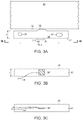
- Figure 3A shows a detailed look at a blade support beam 26.
- the beam 26 is produced typically of standard hardenable stainless steel, although other choices of material could be used. Given a material selection, the stiffness and deflection structural parameters are then dictated by the beam geometry; beam length, width and height, and the beam support boundary conditions, typically simply supported or clamped (fixed) supports.
- a sensor 36 such as a strain gage (36' shown in Figure 3B ), or a fiber optic strain sensor (36" shown in Figure 3C ), or other suitable sensor is attached to the underside of the beam 26. In various embodiments, the strain gage 36' may be oriented in a position ninety degrees rotated with respect to that shown in Figure 3B .
- the beam 26 of Figure 3A is simply supported at hole 38 for receiving a mount 34, and at slot 40 also for receiving a mount 34.
- the slot 40 is used to ensure that the beam is not otherwise constrained lengthwise.
- the hole to hole distance d h-h dictates the active length of the beam.
- the width w would be matched to the conventional spacer width, e.g., about 3.94mm (0.155 inches).
- the width may be chosen for other practical reasons such as sensor cable runs, attachments of accelerometers, strain gage geometry, etc., provided that the sensor output levels are sufficient.
- the height h is chosen in conjunction with the active length to maximize both stiffness and strain. High stiffness is required to avoid initiating blade chatter, while high strain is required to achieve robust sensor measurements.
- the doctor blade 14 rests on the support surfaces 32, which would be narrow in length such that as wear took place, the load would still be primarily applied to the beam midspan.
- the surfaces 32 could be hardened via heat treatment, or a hard coat such as Electroless Nickel coating could be applied. This would promote life of the support surface and thus beam life.
- the underside 42 is straight, which may be a requirement for certain fiber optic cables 44, but is also suitable for strain gage applications as well.
- the blade supporting beam 26 is connected to the doctor blade cartridge sidewalls via a rivet and bushing assembly.
- a rivet 46 expands into a bushing 48, and there is a slight radial clearance (as shown at 52) between the bushing 48 and beam portion 50. This ensures free rotation at the supports.
- the width w b of bushing 48 is slightly larger than the beam width, resulting in a slight gap (as shown at w g ). This avoids friction or constraint caused by the rivet clamping influence.
- the rivet clamping force passes through the bushing, not through the beam.
- There are a number of other ways to achieve this simply support arrangement such as through the use of other fasteners. All other simply supported arrangements, as well as those arrangements achieving a clamped end condition are all considered to be within the spirit of the present invention.
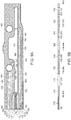
- a blade supporting beam 60 may include midspan depression surfaces 62, as well as an opening 64 in the portion that provides the support surface 66 for supporting the doctor blade. Since the target location for maximum strain measurement is at the midspan, this beam profile may allow higher strain to be achieved at the midspan, without detrimental compromise in stiffness. Support hole 68 and slot 70 dictate the active beam length L b . On the underside of the beam as shown at 72, a groove 74 may be machined in the beam for application and anchoring of the fiber optic cable, and fiber optic strain sensor 76. The bottom surface is otherwise flat, so as to avoid bend radii in the fiber optic sensor and cable.
- FIG. 5 Another beam variation is shown in Figure 5 , which may be well suited for certain strain gage applications.
- the underside 82 of the blade supporting beam 80 is not continuously flat, and instead includes a recessed portion 84. This enables higher strain levels to be achieved for the same stiffness as compared with the fiber optic beam.
- the blade is supported at surface 86. Support hole 88 and slot 90 dictate the active beam length L b .
- the midspan portion 92 of the underside surface 82 is flat for mounting a strain gage 94 as discussed above.
- a gage is preferably an active half bridge or active full bridge for achieving temperature compensation. Temperature compensating gages can be placed on surface 92, or on the outboard surfaces 95.
- the fiber optic sensor system In both the cases of the fiber optic sensor system, and strain gage sensor system, not only can the average value of load be measured, but data acquisition sampling rates can be high to allow dynamic measurements as well.
- the commercially available sampling rate is as high as 1000 samples per second, providing a frequency spectrum available of up to approaching 500 Hz.
- the strain gage data acquisition is available for sample rates up to 100,000 samples per second, providing much that a broader frequency spectrum may be obtained with strain gages.
- the load frequency spectrum may offer great insight in establishing process load signatures.
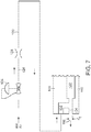
- FIG. 6 Another beam variation that utilizes an alternative sensing means is shown in Figure 6 .
- support hole 102 and slot 104 of the beam 100 dictate the active beam length L b , which is much shorter than the overall length of the beam 100.
- the blade is supported at surface 106.
- the height profile h p of the active beam portion 108 is chosen with the active length 44, such to achieve high stiffness, and high deflection of the underside portion 110, which acts as a lever 46 such that the surface 112 of the underside portion 110 may move relative to surface 114 of the active beam portion 108.
- an air passage discharge exists, and the discharge has an effective area that is regulated by the discharge gap 116.
- the discharge gap 116 may be typically 0.127-0.254mm (0.005 - 0.010 inches), in which inertial flow will dominate.
- an initial gap 116 in the absence of pressure.
- a means of closing this gap is accomplished by turning adjustment screw 118 to preload the lever portion 110, in a manner such that gap 116 is closed initially under no load and room temperature conditions.
- An opening 120 in the internal cavity 122 defined between the active beam portion 108 and the underside portion 110 may also be used to regulate the operating size of the gap in various embodiments.
- air e.g., instrument quality mill air
- a pressure regulating valve 124 discharges air at a set pressure at 126.
- the air will flow through an upstream restrictor 128, reducing in pressure at the discharge side 130 of restrictor 128.
- Air arrives at a beam inlet to a passage 132 that leads to the internal cavity 122 as well as the gap 116 having an opening distance d g . Air will then flow to discharge at surface 134, and radially through discharge gap 116.
- the blade load applied at surface 106 will deflect the beam lever 110 in such a way that gap 116 will be nearly linear with load.
- upstream valve 124 be large enough so that sonic conditions prevail at discharge gap 116, rather than at restrictor 128.
- the resulting relationship between pressure at 130 and blade load at surface 106 will approach linear over most of the load range. If sonic conditions were allowed to prevail at restrictor 128, then the relationship between pressure at 130 and blade load at surface 106 would be significantly nonlinear. A linear relationship is much preferred for sensing purposes. In various embodiments, the sensing may be achieved upstream of the beam (e.g., at valve 124 or restrictor 128) or downstream as air exits the gap 116.
- Figure 8 compares a pressure-load relationship for the two flow conditions.
- the pneumatic beam load measurements will be limited to an average load value or dynamic measurements up to very low frequency at best. This is because of the slow response of the pneumatic system, as compared with the fast response of the fiber optic system and the strain gage system.
- the ambient temperature is in the vicinity of 93°C - 121°C (200°F-250°F) typically, and the beam metal temperature will be that as well.
- the typical temperature of the air supply will be much less, more typically 27°C-38°C (80°F-100°F) total temperature at the upstream source.
- the static temperature will decrease further owing to the high velocity and adiabatic expansion.
- FIGS 9A and 9B show temperature gradients at 160, 162, 164, 166, 168, 170, 172, 174 and 176.
- Figures 10A and 10B show resulting distortion as shown at 180, 182, 184, 186, 188, 190, 192, 194 and 196.
- a low expansion alloy 200 may be applied to an underside surface 202 of the blade supporting beam 100 of Figure 6 by bonding or other mechanical means as shown in Figure 11 .
- the resulting bimetallic characteristic is designed to offset the distortion effect of the temperature gradient.
- Figure 12 shows an embodiment of an alternate approach, in which the topside surface 210 of lever portion 110 is coated with a thermal barrier material 212 such as a temperature resistant polymer, making the lever temperature more uniform and reducing distortion.
- a thermal barrier material 212 such as a temperature resistant polymer, making the lever temperature more uniform and reducing distortion.
- coating 214 can be applied to underside surface 216 of the beam 100.
- FIG. 13A shows another embodiment of the invention in which a blade support beam 220 that includes a support surface 222 and mounting holes 224, 226, also includes an accelerometer 228 attached to the underside surface 230 of the support beam 220.
- the blade is loaded against the surface 222, and as such communicates blade vibration spectrum to the support beam 220. Since the accelerometer has been attached at the midspan on the underside surface 230, the output of the accelerometer 228 as provided at 232 should, under most conditions, have measurable vibration spectrum, and the vibration spectrum of the beam should be indicative of the blade vibration spectrum.
- a piezoelectric dynamic strain gage may be used.
- Figure 13B shows a blade support beam 240 that includes a support surface 242 and mounting holes 244, 246, as well as a piezoelectric dynamic strain gage 248 attached to the underside surface 250 of the support beam 240.
- a strain gage may be a PCB model 740B02.
- dynamic strain levels may be measurable to moderately high frequencies (10kHz), but would thereafter fall off because strain (for constant acceleration) varies inversely with frequency to the 2 power.
- the piezoelectric dynamic strain sensor may have benefits over the conventional strain gage, owing to the high sensitivity of the piezoelectric sensor.
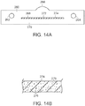
- Figure 14A shows a blade supporting beam 260 in accordance with another embodiment of the invention that has been designed to introduce damping to decrease blade vibration.
- the beam is mounted at mounting holes 262, 264 to a doctor blade cartridge.
- the blade loads against surface 266, which deflects the beam at interior surface 268.
- An integral lower beam portion 270 having an upper surface 272 together with the interior surface 268, provides an enclosed cavity that may be filled with a viscoelastic material 274 to create damping.
- the viscoelastic material could include nanoparticles, such as nanotubes 276 (as shown diagrammatically in Figure 14B ), to enhance damping.
- Figure 15 shows a blade supporting beam in accordance with a further embodiment of the invention that also includes viscoelastic damping.
- the cavity where the damping material 294 resides is of a serpentine geometry defined by inner serpentine surfaces 288, 292.
- the beam is mounted at mounting holes 282, 284 to a doctor blade cartridge.
- the blade loads against surface 286, which deflects the beam at interior surface 288.
- An integral lower beam portion 290 having an upper surface 292 together with the interior surface 288, provides an enclosed cavity that may be filled with the viscoelastic material 294 to create damping.
- the damping material is subjected to shear strain, in addition to tensile and compressive strain.
- a variety of geometries can lead to enhanced damping, all within the scope of the invention.
- a blade supporting member may be provided in the form of a circular spacer that includes viscoelastic material.
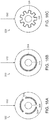
- Figure 16A shows a blade supporting circular spacer 300 that receives a load from the doctor blade as shown at 302 and includes discontinuous cavities within the spacer 300 that include viscoelastic material 304.
- the circular spacer is mounted to the doctor blade cartridge via the central mounting hole 306 for supporting the doctor blade along the top row of spacers.
- the blade acts on the spacer as shown at 302, and introduces strain in viscoelastic material 304.
- Figure 16B shows a blade supporting circular spacer 310 that receives a load from the doctor blade as shown at 312 and includes a continuous cavity within the spacer 310 that includes viscoelastic material 314.
- the circular spacer is mounted to the doctor blade cartridge via the central mounting hole 316 for supporting the doctor blade along the top row of spacers. Again, the blade acts on the spacer as shown at 312, and introduces strain in viscoelastic material 314.
- Figure 16C shows a blade supporting circular spacer 320 that receives a load from the doctor blade as shown at 322 and includes a continuous serpentine cavity within the spacer 320 that includes viscoelastic material 324.
- the circular spacer is mounted to the doctor blade cartridge via the central mounting hole 326 for supporting the doctor blade along the top row of spacers. Again, the blade acts on the spacer as shown at 322, and introduces strain in viscoelastic material 324.
- Figure 17 shows the first vibration mode shape of the pneumatic beam 100 discussed above at least with reference to Figure 6 .
- the surface indicated at 330 has large motion with respect to surface indicated at 332. In fact, most modes of this beam have large relative motion associated with these two surfaces. This is advantageous for introducing damping means between these two surfaces.
- Figure 18 shows a viscoelastic layer 340 sandwiched between these two surfaces 330 and 332.
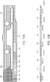
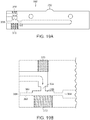
- FIG 19A shows a blade support member that involves the use of a hydrostatic squeeze film for damping in blade supporting beam 350.
- fluid flows to restrictor 354, then into cavity pocket 356.
- the fluid then egresses through side exits 358 and 364.
- An enlarged view of a portion of the blade support member of Figure 19A is shown in Figure 19B .
- the principle of operation is similar to that of hydrostatic seals and bearings.
- the blade vibration spectrum will be communicated to the beam and cause relative motion between surfaces 360 and 362.
- the oscillation of surfaces 360 and 362 will create a substantial cavity pressure response that will be proportional to surface relative velocity, hence substantial damping will be introduced by hydrostatic squeeze film material. It is understood that other geometry adjustments can be made to allow implementation of squeeze film damping, all of which are consistent with the scope of the invention.
- doctor blade holder cartridge may be provided that includes any or all of the blade supporting members discussed above to provide strain sensors and displacement sensors as well as vibration detection and damping.
Landscapes
- Paper (AREA)
- Force Measurement Appropriate To Specific Purposes (AREA)
- Investigating Strength Of Materials By Application Of Mechanical Stress (AREA)
- Coating Apparatus (AREA)
Claims (14)
- Rakelkartusche (12) zur Verwendung in einer Rakelhalterung (10), wobei die Rakelkartusche zur Aufnahme eines Rakels (14) vorgesehen ist, wobei die Rakelkartusche mehrere Rakelhalteelemente (26) umfasst, wobei die Rakelhalteelemente den Rakel halten, dadurch gekennzeichnet, dass mindestens ein Rakelhalteelement (36) eine Belastungsanzeigeeinrichtung (36) umfasst, um ein Signal abzugeben, das die Dehnung eines Rakelhalteelements und/oder die Ablenkung eines Rakelhalteelements anzeigt.
- Rakelkartusche nach Anspruch 1, wobei das mindestens eine Rakelhalteelement ein Balken (26, 100) ist.
- Rakelkartusche nach Anspruch 2, wobei die Belastungsanzeigeeinrichtung einen Glasfaserdehnungssensor (36") zum Erfassen der Dehnung umfasst.
- Rakelkartusche nach Anspruch 2, wobei die Belastungsanzeigeeinrichtung einen Dehnungsmesssensor (36') zum Erfassen der Dehnung umfasst.
- Rakelkartusche nach Anspruch 2, wobei die Belastungsanzeigeeinrichtung einen Balkenhebel (110) umfasst, der zulässt, dass die Rakelbelastung die Strömung durch einen variablen Ablassbegrenzer (128) regelt.
- Rakelkartusche nach Anspruch 5, wobei der Balkenhebel bewirkt, dass der Druck am Ventil (124) in etwa linear mit der Belastung variiert.
- Rakelkartusche nach Anspruch 5, wobei der Balkenhebel ein Bimetallelement umfasst, um die thermische Verformung auszugleichen.
- Rakelkartusche nach Anspruch 5, wobei der Balkenhebel eine thermische Beschichtungsbarriere (212) auf einer Oberfläche davon umfasst, um eine gleichmäßigere Temperatur zu erzeugen und die Verformung zu verringern.
- Rakelkartusche nach Anspruch 1, wobei die Rakelkartusche einen Durchgang umfasst, um einen Durchgang von jeglichen Signalkabeln und fluidleitenden Schläuchen von der Rakelkartusche weg vorzusehen.
- Rakelkartusche nach Anspruch 9, wobei der Durchgang Öffnungen innerhalb des mindestens einen Rakelhalteelements umfasst.
- Rakelkartusche nach Anspruch 2, wobei der Balken eine Trägerfläche (32) zur Berührung des Rakels umfasst und wobei die Trägerfläche etwa auf halbem Weg zwischen einem Paar Tragstützen (34) liegt, mit denen der Balken an der Rakelkartusche befestigt ist.
- Rakelkartusche nach Anspruch 1, wobei das mindestens eine Rakelhalteelement eine Schwingungsmesseinrichtung umfasst, um ein Schwingungssignal vorzusehen, das die Schwingung des mindestens einen Rakelhalteelements anzeigt.
- Rakelkartusche nach Anspruch 12, wobei die Schwingungsmesseinrichtung einen dynamischen Dehnungsmesser (248) zum Messen eines Spektrums der Rakelschwingung umfasst.
- Rakelkartusche nach Anspruch 12, wobei die Schwingungsmesseinrichtung einen Beschleunigungssensor (228) zum Messen eines Spektrums der Rakelschwingung umfasst.
Applications Claiming Priority (2)
| Application Number | Priority Date | Filing Date | Title |
|---|---|---|---|
| US201361816318P | 2013-04-26 | 2013-04-26 | |
| PCT/US2014/035668 WO2014176590A1 (en) | 2013-04-26 | 2014-04-28 | Systems and methods for doctor blade load and vibration measurement as well as blade vibration mitigation |
Publications (3)
| Publication Number | Publication Date |
|---|---|
| EP2989246A1 EP2989246A1 (de) | 2016-03-02 |
| EP2989246A4 EP2989246A4 (de) | 2016-12-28 |
| EP2989246B1 true EP2989246B1 (de) | 2020-10-28 |
Family
ID=51792428
Family Applications (1)
| Application Number | Title | Priority Date | Filing Date |
|---|---|---|---|
| EP14788007.4A Active EP2989246B1 (de) | 2013-04-26 | 2014-04-28 | Systeme zur messung einer rakelbelastung und -schwingung |
Country Status (5)
| Country | Link |
|---|---|
| US (1) | US9506192B2 (de) |
| EP (1) | EP2989246B1 (de) |
| CN (1) | CN105705699B (de) |
| ES (1) | ES2834981T3 (de) |
| WO (1) | WO2014176590A1 (de) |
Families Citing this family (12)
| Publication number | Priority date | Publication date | Assignee | Title |
|---|---|---|---|---|
| US9404895B2 (en) | 2011-10-20 | 2016-08-02 | Nalco Company | Method for early warning chatter detection and asset protection management |
| US20150075928A1 (en) | 2013-04-26 | 2015-03-19 | Kadant Inc. | Systems and methods for providing doctor blade holders with vibration mitigation |
| EP2989246B1 (de) | 2013-04-26 | 2020-10-28 | Kadant Inc. | Systeme zur messung einer rakelbelastung und -schwingung |
| WO2015069915A1 (en) * | 2013-11-06 | 2015-05-14 | Kadant Inc. | Doctor blade holder systems |
| EP3240680B1 (de) * | 2014-12-30 | 2020-05-06 | Kimberly-Clark Worldwide, Inc. | Gedämpfter kreppschaber |
| SE538611C2 (sv) * | 2015-01-30 | 2016-10-04 | Cs Produktion Ab | Schaberanordning |
| US9873981B2 (en) | 2015-07-16 | 2018-01-23 | Gpcp Ip Holdings Llc | Doctor control systems for papermaking machines and related methods |
| WO2019084144A1 (en) | 2017-10-24 | 2019-05-02 | Ecolab Usa Inc. | DETECTION DETECTION IN A PAPER MAKING SYSTEM BY VIBRATION ANALYSIS |
| DE102019117901A1 (de) | 2019-07-03 | 2021-01-07 | Voith Patent Gmbh | Schabvorrichtung und Verfahren zur Ermittlung des Anpressdrucks eines Schabers |
| CN111622011A (zh) * | 2020-06-24 | 2020-09-04 | 苏州静冈刀具有限公司 | 油管式刮刀夹具 |
| CA3208357A1 (en) | 2021-02-16 | 2022-08-25 | William A. Von Drasek | Creping process performance tracking and control |
| DE102023129902A1 (de) | 2023-10-30 | 2025-04-30 | Voith Patent Gmbh | Schabervorrichtung, Verwendung und Verfahren. |
Family Cites Families (14)
| Publication number | Priority date | Publication date | Assignee | Title |
|---|---|---|---|---|
| US5066364A (en) | 1990-06-05 | 1991-11-19 | Thermo Electron-Web Systems, Inc. | Blade edge loading control for pull through doctor blade transfer system |
| US5783042A (en) | 1995-12-06 | 1998-07-21 | Thermo Web Systems, Inc. | System and method of measuring deflected doctor blade angle and loading force |
| FI4290U1 (fi) * | 1999-09-14 | 2000-01-19 | Valmet Corp | Paperikoneen kaavinyksikkö |
| CN100462150C (zh) | 2003-09-08 | 2009-02-18 | 卡登特网络体系股份有限公司 | 刮刀清洗系统 |
| US20070193362A1 (en) * | 2006-02-06 | 2007-08-23 | Ferguson Stephen K | Fiber optic strain gage |
| PL204172B1 (pl) * | 2007-05-16 | 2009-12-31 | Sławomir Stera | Uchwyt skrobaka maszyny papierniczej |
| DE102008001624A1 (de) * | 2008-05-07 | 2009-11-12 | Voith Patent Gmbh | Schabervorrichtung |
| CH700101A1 (de) * | 2008-12-12 | 2010-06-15 | Alfred Simonetti | Messschaber zum Messen eines Schaber-Anpressdrucks. |
| ES2588427T3 (es) * | 2009-01-23 | 2016-11-02 | Kadant Inc. | Sistema para proporcionar un desempeño mejorado de desagüe en una máquina de fabricación de papel |
| EP2403992B1 (de) * | 2009-03-06 | 2015-11-11 | Voith Patent GmbH | Rakel mit spürsystem |
| US20110189378A1 (en) * | 2010-02-04 | 2011-08-04 | Moon So-Ii | Apparatus and method for coating a functional layer |
| DE102011051929B3 (de) * | 2011-07-19 | 2012-10-18 | Gerhard Hertel | Vorrichtung für einen Schaber und Schaberanordnung mit einer solchen Vorrichtung |
| US9404895B2 (en) * | 2011-10-20 | 2016-08-02 | Nalco Company | Method for early warning chatter detection and asset protection management |
| EP2989246B1 (de) | 2013-04-26 | 2020-10-28 | Kadant Inc. | Systeme zur messung einer rakelbelastung und -schwingung |
-
2014
- 2014-04-28 EP EP14788007.4A patent/EP2989246B1/de active Active
- 2014-04-28 CN CN201480030972.3A patent/CN105705699B/zh active Active
- 2014-04-28 ES ES14788007T patent/ES2834981T3/es active Active
- 2014-04-28 US US14/263,335 patent/US9506192B2/en active Active
- 2014-04-28 WO PCT/US2014/035668 patent/WO2014176590A1/en not_active Ceased
Non-Patent Citations (1)
| Title |
|---|
| None * |
Also Published As
| Publication number | Publication date |
|---|---|
| CN105705699B (zh) | 2019-08-02 |
| WO2014176590A1 (en) | 2014-10-30 |
| CN105705699A (zh) | 2016-06-22 |
| EP2989246A1 (de) | 2016-03-02 |
| ES2834981T3 (es) | 2021-06-21 |
| US20150075742A1 (en) | 2015-03-19 |
| US9506192B2 (en) | 2016-11-29 |
| EP2989246A4 (de) | 2016-12-28 |
Similar Documents
| Publication | Publication Date | Title |
|---|---|---|
| EP2989246B1 (de) | Systeme zur messung einer rakelbelastung und -schwingung | |
| CA2794456C (en) | Resonant frequency based pressure sensor | |
| US11834790B2 (en) | Systems and methods for providing doctor blade holders with vibration mitigation | |
| JP2000051758A (ja) | 回転中のロ―ルの不都合な振動を能動的に弱めるための装置と方法及び特に紙又は厚紙から成る紙料ウェッブを走間処理する装置並びに該処理装置で使用するためのロ―ル | |
| JPH02114141A (ja) | ウエブ張力の測定方法および装置 | |
| NZ289206A (en) | Sensing deposit build-up using strain gauge on element deformed by pivoting rod | |
| US8746079B2 (en) | Mass flow sensor and method for determining the mass flow in a pipe | |
| ITMI20131669A1 (it) | Dispositivo e metodo di caratterizzazione delle proprieta' elastiche di un materiale d'attrito | |
| CN108136459A (zh) | 轧机机架、轧制设备和用于主动地减弱轧机机架中的振动的方法 | |
| JP5699052B2 (ja) | スプレー圧力測定装置 | |
| JPH02268239A (ja) | ロール軸受の軸受負荷の把握のための測定装置 | |
| KR101441509B1 (ko) | 박판 주조 스트립 내의 결함원인 확인 및 감소 | |
| Foong et al. | Novel dynamic fatigue-testing device: design and measurements | |
| Holster et al. | Theoretical analysis and experimental verification on the static properties of externally pressurized air-bearing pads with load compensation | |
| US5646338A (en) | Deposition sensing method and apparatus | |
| US5211060A (en) | Bidirectional force sensor | |
| JPS5943306A (ja) | 寸法制御用レ−ザ感知装置 | |
| US7325464B2 (en) | Method and a device for measuring stress forces in refiners | |
| EP0591239A1 (de) | Kapazitiever sensor zum schichtdickenmessen | |
| CN102918372A (zh) | 幅面或条带拉力测量设备及其应用和测定幅面拉力的方法 | |
| US6343501B1 (en) | System and method for determining the process viscosity of a fluid in a film metering device | |
| EP1432517B1 (de) | Verfahren und vorrichtung zum messen von spannungskräften in einem refiner | |
| Torres | Static and Dynamic Characterization of Porous Carbon Aerostatic Gas Films | |
| Rabinowitz et al. | Experimental Evaluation of Squeeze Film Supported Flexible Rotors | |
| JPH11124261A (ja) | 帯状シートのテンション分布測定装置 |
Legal Events
| Date | Code | Title | Description |
|---|---|---|---|
| PUAI | Public reference made under article 153(3) epc to a published international application that has entered the european phase |
Free format text: ORIGINAL CODE: 0009012 |
|
| 17P | Request for examination filed |
Effective date: 20151126 |
|
| AK | Designated contracting states |
Kind code of ref document: A1 Designated state(s): AL AT BE BG CH CY CZ DE DK EE ES FI FR GB GR HR HU IE IS IT LI LT LU LV MC MK MT NL NO PL PT RO RS SE SI SK SM TR |
|
| AX | Request for extension of the european patent |
Extension state: BA ME |
|
| DAX | Request for extension of the european patent (deleted) | ||
| A4 | Supplementary search report drawn up and despatched |
Effective date: 20161125 |
|
| RIC1 | Information provided on ipc code assigned before grant |
Ipc: D21G 3/04 20060101ALI20161121BHEP Ipc: D21G 3/00 20060101AFI20161121BHEP |
|
| GRAP | Despatch of communication of intention to grant a patent |
Free format text: ORIGINAL CODE: EPIDOSNIGR1 |
|
| STAA | Information on the status of an ep patent application or granted ep patent |
Free format text: STATUS: GRANT OF PATENT IS INTENDED |
|
| INTG | Intention to grant announced |
Effective date: 20200519 |
|
| GRAS | Grant fee paid |
Free format text: ORIGINAL CODE: EPIDOSNIGR3 |
|
| GRAA | (expected) grant |
Free format text: ORIGINAL CODE: 0009210 |
|
| STAA | Information on the status of an ep patent application or granted ep patent |
Free format text: STATUS: THE PATENT HAS BEEN GRANTED |
|
| AK | Designated contracting states |
Kind code of ref document: B1 Designated state(s): AL AT BE BG CH CY CZ DE DK EE ES FI FR GB GR HR HU IE IS IT LI LT LU LV MC MK MT NL NO PL PT RO RS SE SI SK SM TR |
|
| REG | Reference to a national code |
Ref country code: GB Ref legal event code: FG4D |
|
| REG | Reference to a national code |
Ref country code: CH Ref legal event code: EP |
|
| REG | Reference to a national code |
Ref country code: DE Ref legal event code: R096 Ref document number: 602014071744 Country of ref document: DE |
|
| REG | Reference to a national code |
Ref country code: AT Ref legal event code: REF Ref document number: 1328350 Country of ref document: AT Kind code of ref document: T Effective date: 20201115 |
|
| REG | Reference to a national code |
Ref country code: IE Ref legal event code: FG4D |
|
| REG | Reference to a national code |
Ref country code: FI Ref legal event code: FGE |
|
| REG | Reference to a national code |
Ref country code: DE Ref legal event code: R082 Ref document number: 602014071744 Country of ref document: DE Representative=s name: HL KEMPNER PATENTANWAELTE, SOLICITORS (ENGLAND, DE Ref country code: DE Ref legal event code: R082 Ref document number: 602014071744 Country of ref document: DE Representative=s name: HL KEMPNER PATENTANWALT, RECHTSANWALT, SOLICIT, DE Ref country code: DE Ref legal event code: R082 Ref document number: 602014071744 Country of ref document: DE Representative=s name: HL KEMPNER PARTG MBB, DE |
|
| REG | Reference to a national code |
Ref country code: SE Ref legal event code: TRGR |
|
| REG | Reference to a national code |
Ref country code: AT Ref legal event code: MK05 Ref document number: 1328350 Country of ref document: AT Kind code of ref document: T Effective date: 20201028 |
|
| REG | Reference to a national code |
Ref country code: NL Ref legal event code: MP Effective date: 20201028 |
|
| PG25 | Lapsed in a contracting state [announced via postgrant information from national office to epo] |
Ref country code: GR Free format text: LAPSE BECAUSE OF FAILURE TO SUBMIT A TRANSLATION OF THE DESCRIPTION OR TO PAY THE FEE WITHIN THE PRESCRIBED TIME-LIMIT Effective date: 20210129 Ref country code: NL Free format text: LAPSE BECAUSE OF FAILURE TO SUBMIT A TRANSLATION OF THE DESCRIPTION OR TO PAY THE FEE WITHIN THE PRESCRIBED TIME-LIMIT Effective date: 20201028 Ref country code: PT Free format text: LAPSE BECAUSE OF FAILURE TO SUBMIT A TRANSLATION OF THE DESCRIPTION OR TO PAY THE FEE WITHIN THE PRESCRIBED TIME-LIMIT Effective date: 20210301 Ref country code: NO Free format text: LAPSE BECAUSE OF FAILURE TO SUBMIT A TRANSLATION OF THE DESCRIPTION OR TO PAY THE FEE WITHIN THE PRESCRIBED TIME-LIMIT Effective date: 20210128 Ref country code: RS Free format text: LAPSE BECAUSE OF FAILURE TO SUBMIT A TRANSLATION OF THE DESCRIPTION OR TO PAY THE FEE WITHIN THE PRESCRIBED TIME-LIMIT Effective date: 20201028 |
|
| REG | Reference to a national code |
Ref country code: LT Ref legal event code: MG4D |
|
| PG25 | Lapsed in a contracting state [announced via postgrant information from national office to epo] |
Ref country code: BG Free format text: LAPSE BECAUSE OF FAILURE TO SUBMIT A TRANSLATION OF THE DESCRIPTION OR TO PAY THE FEE WITHIN THE PRESCRIBED TIME-LIMIT Effective date: 20210128 Ref country code: AT Free format text: LAPSE BECAUSE OF FAILURE TO SUBMIT A TRANSLATION OF THE DESCRIPTION OR TO PAY THE FEE WITHIN THE PRESCRIBED TIME-LIMIT Effective date: 20201028 Ref country code: LV Free format text: LAPSE BECAUSE OF FAILURE TO SUBMIT A TRANSLATION OF THE DESCRIPTION OR TO PAY THE FEE WITHIN THE PRESCRIBED TIME-LIMIT Effective date: 20201028 Ref country code: PL Free format text: LAPSE BECAUSE OF FAILURE TO SUBMIT A TRANSLATION OF THE DESCRIPTION OR TO PAY THE FEE WITHIN THE PRESCRIBED TIME-LIMIT Effective date: 20201028 Ref country code: IS Free format text: LAPSE BECAUSE OF FAILURE TO SUBMIT A TRANSLATION OF THE DESCRIPTION OR TO PAY THE FEE WITHIN THE PRESCRIBED TIME-LIMIT Effective date: 20210228 |
|
| REG | Reference to a national code |
Ref country code: ES Ref legal event code: FG2A Ref document number: 2834981 Country of ref document: ES Kind code of ref document: T3 Effective date: 20210621 |
|
| PG25 | Lapsed in a contracting state [announced via postgrant information from national office to epo] |
Ref country code: HR Free format text: LAPSE BECAUSE OF FAILURE TO SUBMIT A TRANSLATION OF THE DESCRIPTION OR TO PAY THE FEE WITHIN THE PRESCRIBED TIME-LIMIT Effective date: 20201028 |
|
| REG | Reference to a national code |
Ref country code: DE Ref legal event code: R097 Ref document number: 602014071744 Country of ref document: DE |
|
| PG25 | Lapsed in a contracting state [announced via postgrant information from national office to epo] |
Ref country code: SM Free format text: LAPSE BECAUSE OF FAILURE TO SUBMIT A TRANSLATION OF THE DESCRIPTION OR TO PAY THE FEE WITHIN THE PRESCRIBED TIME-LIMIT Effective date: 20201028 Ref country code: EE Free format text: LAPSE BECAUSE OF FAILURE TO SUBMIT A TRANSLATION OF THE DESCRIPTION OR TO PAY THE FEE WITHIN THE PRESCRIBED TIME-LIMIT Effective date: 20201028 Ref country code: CZ Free format text: LAPSE BECAUSE OF FAILURE TO SUBMIT A TRANSLATION OF THE DESCRIPTION OR TO PAY THE FEE WITHIN THE PRESCRIBED TIME-LIMIT Effective date: 20201028 Ref country code: SK Free format text: LAPSE BECAUSE OF FAILURE TO SUBMIT A TRANSLATION OF THE DESCRIPTION OR TO PAY THE FEE WITHIN THE PRESCRIBED TIME-LIMIT Effective date: 20201028 Ref country code: RO Free format text: LAPSE BECAUSE OF FAILURE TO SUBMIT A TRANSLATION OF THE DESCRIPTION OR TO PAY THE FEE WITHIN THE PRESCRIBED TIME-LIMIT Effective date: 20201028 Ref country code: LT Free format text: LAPSE BECAUSE OF FAILURE TO SUBMIT A TRANSLATION OF THE DESCRIPTION OR TO PAY THE FEE WITHIN THE PRESCRIBED TIME-LIMIT Effective date: 20201028 |
|
| PG25 | Lapsed in a contracting state [announced via postgrant information from national office to epo] |
Ref country code: DK Free format text: LAPSE BECAUSE OF FAILURE TO SUBMIT A TRANSLATION OF THE DESCRIPTION OR TO PAY THE FEE WITHIN THE PRESCRIBED TIME-LIMIT Effective date: 20201028 |
|
| PLBE | No opposition filed within time limit |
Free format text: ORIGINAL CODE: 0009261 |
|
| STAA | Information on the status of an ep patent application or granted ep patent |
Free format text: STATUS: NO OPPOSITION FILED WITHIN TIME LIMIT |
|
| 26N | No opposition filed |
Effective date: 20210729 |
|
| PG25 | Lapsed in a contracting state [announced via postgrant information from national office to epo] |
Ref country code: AL Free format text: LAPSE BECAUSE OF FAILURE TO SUBMIT A TRANSLATION OF THE DESCRIPTION OR TO PAY THE FEE WITHIN THE PRESCRIBED TIME-LIMIT Effective date: 20201028 |
|
| PG25 | Lapsed in a contracting state [announced via postgrant information from national office to epo] |
Ref country code: MC Free format text: LAPSE BECAUSE OF FAILURE TO SUBMIT A TRANSLATION OF THE DESCRIPTION OR TO PAY THE FEE WITHIN THE PRESCRIBED TIME-LIMIT Effective date: 20201028 Ref country code: SI Free format text: LAPSE BECAUSE OF FAILURE TO SUBMIT A TRANSLATION OF THE DESCRIPTION OR TO PAY THE FEE WITHIN THE PRESCRIBED TIME-LIMIT Effective date: 20201028 |
|
| GBPC | Gb: european patent ceased through non-payment of renewal fee |
Effective date: 20210428 |
|
| PG25 | Lapsed in a contracting state [announced via postgrant information from national office to epo] |
Ref country code: LU Free format text: LAPSE BECAUSE OF NON-PAYMENT OF DUE FEES Effective date: 20210428 |
|
| REG | Reference to a national code |
Ref country code: BE Ref legal event code: MM Effective date: 20210430 |
|
| PG25 | Lapsed in a contracting state [announced via postgrant information from national office to epo] |
Ref country code: GB Free format text: LAPSE BECAUSE OF NON-PAYMENT OF DUE FEES Effective date: 20210428 Ref country code: FR Free format text: LAPSE BECAUSE OF NON-PAYMENT OF DUE FEES Effective date: 20210430 Ref country code: CH Free format text: LAPSE BECAUSE OF NON-PAYMENT OF DUE FEES Effective date: 20210430 Ref country code: LI Free format text: LAPSE BECAUSE OF NON-PAYMENT OF DUE FEES Effective date: 20210430 |
|
| PG25 | Lapsed in a contracting state [announced via postgrant information from national office to epo] |
Ref country code: IE Free format text: LAPSE BECAUSE OF NON-PAYMENT OF DUE FEES Effective date: 20210428 |
|
| PG25 | Lapsed in a contracting state [announced via postgrant information from national office to epo] |
Ref country code: IS Free format text: LAPSE BECAUSE OF FAILURE TO SUBMIT A TRANSLATION OF THE DESCRIPTION OR TO PAY THE FEE WITHIN THE PRESCRIBED TIME-LIMIT Effective date: 20210228 |
|
| PG25 | Lapsed in a contracting state [announced via postgrant information from national office to epo] |
Ref country code: BE Free format text: LAPSE BECAUSE OF NON-PAYMENT OF DUE FEES Effective date: 20210430 |
|
| PG25 | Lapsed in a contracting state [announced via postgrant information from national office to epo] |
Ref country code: HU Free format text: LAPSE BECAUSE OF FAILURE TO SUBMIT A TRANSLATION OF THE DESCRIPTION OR TO PAY THE FEE WITHIN THE PRESCRIBED TIME-LIMIT; INVALID AB INITIO Effective date: 20140428 |
|
| PG25 | Lapsed in a contracting state [announced via postgrant information from national office to epo] |
Ref country code: CY Free format text: LAPSE BECAUSE OF FAILURE TO SUBMIT A TRANSLATION OF THE DESCRIPTION OR TO PAY THE FEE WITHIN THE PRESCRIBED TIME-LIMIT Effective date: 20201028 |
|
| P01 | Opt-out of the competence of the unified patent court (upc) registered |
Effective date: 20230525 |
|
| PG25 | Lapsed in a contracting state [announced via postgrant information from national office to epo] |
Ref country code: MK Free format text: LAPSE BECAUSE OF FAILURE TO SUBMIT A TRANSLATION OF THE DESCRIPTION OR TO PAY THE FEE WITHIN THE PRESCRIBED TIME-LIMIT Effective date: 20201028 |
|
| PGFP | Annual fee paid to national office [announced via postgrant information from national office to epo] |
Ref country code: ES Payment date: 20240513 Year of fee payment: 11 |
|
| PGFP | Annual fee paid to national office [announced via postgrant information from national office to epo] |
Ref country code: FI Payment date: 20240425 Year of fee payment: 11 |
|
| PG25 | Lapsed in a contracting state [announced via postgrant information from national office to epo] |
Ref country code: MT Free format text: LAPSE BECAUSE OF FAILURE TO SUBMIT A TRANSLATION OF THE DESCRIPTION OR TO PAY THE FEE WITHIN THE PRESCRIBED TIME-LIMIT Effective date: 20201028 |
|
| PGFP | Annual fee paid to national office [announced via postgrant information from national office to epo] |
Ref country code: SE Payment date: 20250319 Year of fee payment: 12 |
|
| PGFP | Annual fee paid to national office [announced via postgrant information from national office to epo] |
Ref country code: IT Payment date: 20250319 Year of fee payment: 12 |
|
| PGFP | Annual fee paid to national office [announced via postgrant information from national office to epo] |
Ref country code: DE Payment date: 20250319 Year of fee payment: 12 |