EP2987672B1 - Système de contrôle - Google Patents
Système de contrôle Download PDFInfo
- Publication number
- EP2987672B1 EP2987672B1 EP15181614.7A EP15181614A EP2987672B1 EP 2987672 B1 EP2987672 B1 EP 2987672B1 EP 15181614 A EP15181614 A EP 15181614A EP 2987672 B1 EP2987672 B1 EP 2987672B1
- Authority
- EP
- European Patent Office
- Prior art keywords
- operation tool
- mounting base
- hydraulic valve
- control
- tool
- Prior art date
- Legal status (The legal status is an assumption and is not a legal conclusion. Google has not performed a legal analysis and makes no representation as to the accuracy of the status listed.)
- Active
Links
- 238000006073 displacement reaction Methods 0.000 description 9
- 230000005540 biological transmission Effects 0.000 description 7
- 238000010586 diagram Methods 0.000 description 3
- 238000001514 detection method Methods 0.000 description 2
- 238000004590 computer program Methods 0.000 description 1
- 238000010276 construction Methods 0.000 description 1
- 239000012530 fluid Substances 0.000 description 1
- 210000000245 forearm Anatomy 0.000 description 1
- 230000010354 integration Effects 0.000 description 1
- 230000007935 neutral effect Effects 0.000 description 1
- 230000000284 resting effect Effects 0.000 description 1
- 230000005236 sound signal Effects 0.000 description 1
Images


Classifications
-
- B—PERFORMING OPERATIONS; TRANSPORTING
- B60—VEHICLES IN GENERAL
- B60K—ARRANGEMENT OR MOUNTING OF PROPULSION UNITS OR OF TRANSMISSIONS IN VEHICLES; ARRANGEMENT OR MOUNTING OF PLURAL DIVERSE PRIME-MOVERS IN VEHICLES; AUXILIARY DRIVES FOR VEHICLES; INSTRUMENTATION OR DASHBOARDS FOR VEHICLES; ARRANGEMENTS IN CONNECTION WITH COOLING, AIR INTAKE, GAS EXHAUST OR FUEL SUPPLY OF PROPULSION UNITS IN VEHICLES
- B60K35/00—Instruments specially adapted for vehicles; Arrangement of instruments in or on vehicles
- B60K35/10—Input arrangements, i.e. from user to vehicle, associated with vehicle functions or specially adapted therefor
-
- F—MECHANICAL ENGINEERING; LIGHTING; HEATING; WEAPONS; BLASTING
- F15—FLUID-PRESSURE ACTUATORS; HYDRAULICS OR PNEUMATICS IN GENERAL
- F15B—SYSTEMS ACTING BY MEANS OF FLUIDS IN GENERAL; FLUID-PRESSURE ACTUATORS, e.g. SERVOMOTORS; DETAILS OF FLUID-PRESSURE SYSTEMS, NOT OTHERWISE PROVIDED FOR
- F15B11/00—Servomotor systems without provision for follow-up action; Circuits therefor
- F15B11/16—Servomotor systems without provision for follow-up action; Circuits therefor with two or more servomotors
-
- B—PERFORMING OPERATIONS; TRANSPORTING
- B60—VEHICLES IN GENERAL
- B60K—ARRANGEMENT OR MOUNTING OF PROPULSION UNITS OR OF TRANSMISSIONS IN VEHICLES; ARRANGEMENT OR MOUNTING OF PLURAL DIVERSE PRIME-MOVERS IN VEHICLES; AUXILIARY DRIVES FOR VEHICLES; INSTRUMENTATION OR DASHBOARDS FOR VEHICLES; ARRANGEMENTS IN CONNECTION WITH COOLING, AIR INTAKE, GAS EXHAUST OR FUEL SUPPLY OF PROPULSION UNITS IN VEHICLES
- B60K35/00—Instruments specially adapted for vehicles; Arrangement of instruments in or on vehicles
- B60K35/50—Instruments characterised by their means of attachment to or integration in the vehicle
-
- F—MECHANICAL ENGINEERING; LIGHTING; HEATING; WEAPONS; BLASTING
- F15—FLUID-PRESSURE ACTUATORS; HYDRAULICS OR PNEUMATICS IN GENERAL
- F15B—SYSTEMS ACTING BY MEANS OF FLUIDS IN GENERAL; FLUID-PRESSURE ACTUATORS, e.g. SERVOMOTORS; DETAILS OF FLUID-PRESSURE SYSTEMS, NOT OTHERWISE PROVIDED FOR
- F15B13/00—Details of servomotor systems ; Valves for servomotor systems
- F15B13/02—Fluid distribution or supply devices characterised by their adaptation to the control of servomotors
- F15B13/06—Fluid distribution or supply devices characterised by their adaptation to the control of servomotors for use with two or more servomotors
-
- F—MECHANICAL ENGINEERING; LIGHTING; HEATING; WEAPONS; BLASTING
- F15—FLUID-PRESSURE ACTUATORS; HYDRAULICS OR PNEUMATICS IN GENERAL
- F15B—SYSTEMS ACTING BY MEANS OF FLUIDS IN GENERAL; FLUID-PRESSURE ACTUATORS, e.g. SERVOMOTORS; DETAILS OF FLUID-PRESSURE SYSTEMS, NOT OTHERWISE PROVIDED FOR
- F15B13/00—Details of servomotor systems ; Valves for servomotor systems
- F15B13/14—Special measures for giving the operating person a "feeling" of the response of the actuated device
-
- G—PHYSICS
- G05—CONTROLLING; REGULATING
- G05G—CONTROL DEVICES OR SYSTEMS INSOFAR AS CHARACTERISED BY MECHANICAL FEATURES ONLY
- G05G9/00—Manually-actuated control mechanisms provided with one single controlling member co-operating with two or more controlled members, e.g. selectively, simultaneously
- G05G9/02—Manually-actuated control mechanisms provided with one single controlling member co-operating with two or more controlled members, e.g. selectively, simultaneously the controlling member being movable in different independent ways, movement in each individual way actuating one controlled member only
- G05G9/04—Manually-actuated control mechanisms provided with one single controlling member co-operating with two or more controlled members, e.g. selectively, simultaneously the controlling member being movable in different independent ways, movement in each individual way actuating one controlled member only in which movement in two or more ways can occur simultaneously
- G05G9/047—Manually-actuated control mechanisms provided with one single controlling member co-operating with two or more controlled members, e.g. selectively, simultaneously the controlling member being movable in different independent ways, movement in each individual way actuating one controlled member only in which movement in two or more ways can occur simultaneously the controlling member being movable by hand about orthogonal axes, e.g. joysticks
- G05G9/04785—Manually-actuated control mechanisms provided with one single controlling member co-operating with two or more controlled members, e.g. selectively, simultaneously the controlling member being movable in different independent ways, movement in each individual way actuating one controlled member only in which movement in two or more ways can occur simultaneously the controlling member being movable by hand about orthogonal axes, e.g. joysticks the controlling member being the operating part of a switch arrangement
- G05G9/04788—Manually-actuated control mechanisms provided with one single controlling member co-operating with two or more controlled members, e.g. selectively, simultaneously the controlling member being movable in different independent ways, movement in each individual way actuating one controlled member only in which movement in two or more ways can occur simultaneously the controlling member being movable by hand about orthogonal axes, e.g. joysticks the controlling member being the operating part of a switch arrangement comprising additional control elements
-
- B—PERFORMING OPERATIONS; TRANSPORTING
- B60—VEHICLES IN GENERAL
- B60K—ARRANGEMENT OR MOUNTING OF PROPULSION UNITS OR OF TRANSMISSIONS IN VEHICLES; ARRANGEMENT OR MOUNTING OF PLURAL DIVERSE PRIME-MOVERS IN VEHICLES; AUXILIARY DRIVES FOR VEHICLES; INSTRUMENTATION OR DASHBOARDS FOR VEHICLES; ARRANGEMENTS IN CONNECTION WITH COOLING, AIR INTAKE, GAS EXHAUST OR FUEL SUPPLY OF PROPULSION UNITS IN VEHICLES
- B60K2360/00—Indexing scheme associated with groups B60K35/00 or B60K37/00 relating to details of instruments or dashboards
- B60K2360/122—Instrument input devices with reconfigurable control functions, e.g. reconfigurable menus
-
- B—PERFORMING OPERATIONS; TRANSPORTING
- B60—VEHICLES IN GENERAL
- B60K—ARRANGEMENT OR MOUNTING OF PROPULSION UNITS OR OF TRANSMISSIONS IN VEHICLES; ARRANGEMENT OR MOUNTING OF PLURAL DIVERSE PRIME-MOVERS IN VEHICLES; AUXILIARY DRIVES FOR VEHICLES; INSTRUMENTATION OR DASHBOARDS FOR VEHICLES; ARRANGEMENTS IN CONNECTION WITH COOLING, AIR INTAKE, GAS EXHAUST OR FUEL SUPPLY OF PROPULSION UNITS IN VEHICLES
- B60K2360/00—Indexing scheme associated with groups B60K35/00 or B60K37/00 relating to details of instruments or dashboards
- B60K2360/133—Multidirectional input devices for instruments
- B60K2360/135—Joysticks
-
- B—PERFORMING OPERATIONS; TRANSPORTING
- B60—VEHICLES IN GENERAL
- B60K—ARRANGEMENT OR MOUNTING OF PROPULSION UNITS OR OF TRANSMISSIONS IN VEHICLES; ARRANGEMENT OR MOUNTING OF PLURAL DIVERSE PRIME-MOVERS IN VEHICLES; AUXILIARY DRIVES FOR VEHICLES; INSTRUMENTATION OR DASHBOARDS FOR VEHICLES; ARRANGEMENTS IN CONNECTION WITH COOLING, AIR INTAKE, GAS EXHAUST OR FUEL SUPPLY OF PROPULSION UNITS IN VEHICLES
- B60K2360/00—Indexing scheme associated with groups B60K35/00 or B60K37/00 relating to details of instruments or dashboards
- B60K2360/139—Clusters of instrument input devices
-
- B—PERFORMING OPERATIONS; TRANSPORTING
- B60—VEHICLES IN GENERAL
- B60K—ARRANGEMENT OR MOUNTING OF PROPULSION UNITS OR OF TRANSMISSIONS IN VEHICLES; ARRANGEMENT OR MOUNTING OF PLURAL DIVERSE PRIME-MOVERS IN VEHICLES; AUXILIARY DRIVES FOR VEHICLES; INSTRUMENTATION OR DASHBOARDS FOR VEHICLES; ARRANGEMENTS IN CONNECTION WITH COOLING, AIR INTAKE, GAS EXHAUST OR FUEL SUPPLY OF PROPULSION UNITS IN VEHICLES
- B60K2360/00—Indexing scheme associated with groups B60K35/00 or B60K37/00 relating to details of instruments or dashboards
- B60K2360/60—Structural details of dashboards or instruments
- B60K2360/61—Specially adapted for utility vehicles
-
- B—PERFORMING OPERATIONS; TRANSPORTING
- B60—VEHICLES IN GENERAL
- B60K—ARRANGEMENT OR MOUNTING OF PROPULSION UNITS OR OF TRANSMISSIONS IN VEHICLES; ARRANGEMENT OR MOUNTING OF PLURAL DIVERSE PRIME-MOVERS IN VEHICLES; AUXILIARY DRIVES FOR VEHICLES; INSTRUMENTATION OR DASHBOARDS FOR VEHICLES; ARRANGEMENTS IN CONNECTION WITH COOLING, AIR INTAKE, GAS EXHAUST OR FUEL SUPPLY OF PROPULSION UNITS IN VEHICLES
- B60K2360/00—Indexing scheme associated with groups B60K35/00 or B60K37/00 relating to details of instruments or dashboards
- B60K2360/60—Structural details of dashboards or instruments
- B60K2360/68—Features of instruments
-
- B—PERFORMING OPERATIONS; TRANSPORTING
- B60—VEHICLES IN GENERAL
- B60K—ARRANGEMENT OR MOUNTING OF PROPULSION UNITS OR OF TRANSMISSIONS IN VEHICLES; ARRANGEMENT OR MOUNTING OF PLURAL DIVERSE PRIME-MOVERS IN VEHICLES; AUXILIARY DRIVES FOR VEHICLES; INSTRUMENTATION OR DASHBOARDS FOR VEHICLES; ARRANGEMENTS IN CONNECTION WITH COOLING, AIR INTAKE, GAS EXHAUST OR FUEL SUPPLY OF PROPULSION UNITS IN VEHICLES
- B60K2360/00—Indexing scheme associated with groups B60K35/00 or B60K37/00 relating to details of instruments or dashboards
- B60K2360/822—Adjustment of instruments during mounting
-
- B—PERFORMING OPERATIONS; TRANSPORTING
- B60—VEHICLES IN GENERAL
- B60K—ARRANGEMENT OR MOUNTING OF PROPULSION UNITS OR OF TRANSMISSIONS IN VEHICLES; ARRANGEMENT OR MOUNTING OF PLURAL DIVERSE PRIME-MOVERS IN VEHICLES; AUXILIARY DRIVES FOR VEHICLES; INSTRUMENTATION OR DASHBOARDS FOR VEHICLES; ARRANGEMENTS IN CONNECTION WITH COOLING, AIR INTAKE, GAS EXHAUST OR FUEL SUPPLY OF PROPULSION UNITS IN VEHICLES
- B60K2360/00—Indexing scheme associated with groups B60K35/00 or B60K37/00 relating to details of instruments or dashboards
- B60K2360/828—Mounting or fastening exchangeable modules
-
- B—PERFORMING OPERATIONS; TRANSPORTING
- B60—VEHICLES IN GENERAL
- B60Y—INDEXING SCHEME RELATING TO ASPECTS CROSS-CUTTING VEHICLE TECHNOLOGY
- B60Y2200/00—Type of vehicle
- B60Y2200/20—Off-Road Vehicles
- B60Y2200/22—Agricultural vehicles
- B60Y2200/221—Tractors
Definitions
- the present invention relates to an operation control system for a work apparatus provided to a work vehicle.
- auxiliary control valves a plurality of hydraulic valves (often referred to as auxiliary control valves) are grouped as a unit and arranged on the rear of such a work vehicle.
- a front loader is sometimes provided to a front section of the work vehicle.
- a tractor disclosed in Japanese Patent Laid Open Publication No. 2006-306236 ( Figs. 1 and 3 )
- three auxiliary control valves are arranged on the rear of the tractor, and a tiller apparatus is attached through a hydraulic lifting link mechanism.
- a front manipulation section is provided with three auxiliary control levers that are linked to the auxiliary control valves.
- the front section of a tractor is provided with a front loader. Further, auxiliary control valves are also provided on the rear section of this tractor.
- a side console provided in a cabin interior is equipped with two auxiliary control levers controlling the auxiliary control valves.
- a joystick lever is provided to a control box on a right side of a driver seat, with the joystick lever being interlocked/linked to the control valves of the front loader.
- This type of work vehicle such as the tractors described above, is provided with work apparatuses on the front of the vehicle body, such as a front loader controlled through hydraulic pressure, or on the back of the vehicle body, such as a tiller apparatus controlled through hydraulic pressure.
- various operation tools are needed in order to control a plurality of auxiliary control valves, which complicates positioning of tools in the manipulation section.
- the operation tools required are not only single-operation tools controlling ON/OFF modes as shown in Japanese Patent Laid Open Publication No. 2006-306236 , but also a multi-operation tool (such as a joystick) controlling a plurality of operations as shown in Japanese Patent Laid Open Publication No. 2007-92284 .
- EP 2 557 238 A1 discloses an operation control system configured to be installed on a work vehicle which a work apparatus is arranged on or mounted to, comprising: a controller configured to control the work apparatus; a first hydraulic valve and a second hydraulic valve configured to control hydraulic pressure supply to the work apparatus; and an operation unit configured to provide an operation input signal to the controller, and discloses the preamble of claim 1.
- WO 2005/025919 A1 discloses a vehicle system where at least two modules are interexchangable.
- US 2007/0295551 A1 discloses a control console associated with an armrest extending from a seat in a forward direction generally parallel with a seat plane of symmetry and having an upper armrest surface intended to support an operator's forearm, comprising a base operatively connected to the armrest, and at least one operator interface device operatively connected to the base.
- the present invention provides an operation control system that efficiently arranges operation tools required for operating hydraulic valves needed for a work apparatus equipped to a work vehicle.
- the present invention provides an operation control system according to claim 1.
- the operation unit which is in general arranged near the driver seat, is provided with a plurality of mounting bases that mount operation tools to be operated by a driver.
- the operation tools include a single-operation tool and a multi-operation tool.
- the single-operation tool is capable of a single operation such as an on/off switch, or a seesaw switch.
- the multi-operation tool is capable of operational displacement in a plurality of directions.
- the operation unit can flexibly adapt for the hydraulic valves needed for a work apparatus regardless of whether a single-operation tool or a multi-operation tool controls the hydraulic valves controlling hydraulic pressure supply to a work apparatus equipped to a work vehicle.
- the first mounting base and the second mounting base can be used for mounting two single-operation tools, or can be used for mounting one multi-operation tool. Which operation tool is mounted depends on the work apparatus. Accordingly, it is possible to efficiently and flexibly arrange operation tools required for operating hydraulic valves needed for a work apparatus equipped to a work vehicle.
- the multi-operation tool is configured such that movement of the multi-operation tool along one axis generates a control signal via the first mounting base and that movement of the multi-operation tool along another axis generates a control signal via the second mounting base.
- a multi-operation tool moving along a plurality of axis directions is preferably employed. Operational displacement in each of the different directions is separately transmitted to the controller. Thereby it makes it possible to control complex movements of the work apparatus.
- a front loader will be provided to the work vehicle, such a multi-operation tool is preferably mounted straddling over the first mounting base and the second mounting base.
- the multi-operation tool is configured such that movement of the multi-operation tool along one axis sends a signal to the controller via the first mounting base and that movement of the multi-operation tool along another axis sends a signal to the controller via the second mounting base.
- the multi-operation tool is a joystick-type tool.
- An operation input signal generated based on displacement in one axial direction of the joystick-type tool is sent to the controller via the first mounting base, and an operation input signal generated based on displacement in another axial direction of the joystick-type tool is sent to the controller via the second mounting base.
- a joystick-type tool pivoting in a plurality of axis directions is preferably employed. Therefore, the joystick-type tool is preferably provided utilizing the first mounting base and the second mounting base. Operational displacement in each of the different directions is separately transmitted to the controller. Thereby it makes it possible to control complex movements of the work apparatus.
- one joystick-type tool is preferably mounted straddling over the first mounting base and the second mounting base.
- the multi-operation tool is a joystick.
- the multi-operation tool is a joystick-type tool as mentioned above.
- the controller includes a valve mode controller configured to perform hydraulic valve mode control that controls, based on the operation input signal, the first hydraulic valve and the second hydraulic valve.
- the controller includes a loader mode controller configured to perform front loader mode control that controls, based on the operation input signal, a front loader via a front loader hydraulic valve unit.
- the operation control system is preferably configured to control a front loader as the work apparatus.
- the controller includes the valve mode controller and the loader mode controller.
- the multi-operation tool such as the joystick-type tool can utilize operational displacement in different directions for controlling a first control valve and a second control valve, respectively.
- one multi-operation tool can be used as two single-operation tools.
- the controller side can select an appropriate mode from two modes for the multi-operation tool.
- the joystick-type tool is provided with a selection device selecting between the hydraulic valve mode control and the front loader mode control, a driver can select a required hydraulic valve mode without error, thereby improving usability of the joystick-type tool.
- the multi-operation tool includes at least one of: a hydraulic mode selection device mounted thereon; and a selector switch configured to switch between a hydraulic valve mode control and a front loader mode control.
- the operation control system is preferably configured to control a front loader as the work apparatus.
- the selector switch is used to switch the hydraulic valve mode control and the front loader mode control.
- the two modes can be further preferably selected by moving a joy stick as the multi-operation tool along two different directions respectively.
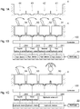
- FIG. 1A is a vertical cross sectional figure illustrating an operation unit 4 provided near a driver seat, with the operation unit 4 including a first mounting base 41, a second mounting base 42, a third mounting base 43, and a fourth mounting base 44 that are adjacently aligned with one another.
- Each of these mounting bases includes a mounting space, wherein an operation tool controlled by a driver is mounted.
- the tool can have the form of a switch (including a button, dial, volume control, etc.) or a lever type.
- Fig. 1B shows a state where operation tools, which operate hydraulic valves supplying hydraulic pressure to a work apparatus 22 (see Fig. 2 ), are mounted to each of the mounting bases of the operation unit 4.
- a first single-operation tool 91 is mounted to the first mounting base 41;
- a second single-operation tool 92 is mounted to the second mounting base 42;
- a third single-operation tool 93 is mounted to the third mounting base 43;
- a fourth single-operation tool 94 is mounted to the fourth mounting base 44.
- Single-operation tool in this example is a tool switchable between two modes. For example, the single-operation tool is switched to one mode for opening the hydraulic valve, or the other mode for closing the hydraulic valve.
- the single-operation tool is switched to one mode for opening the hydraulic valve, or the other mode for closing the hydraulic valve.
- Fig. 1C illustrates another mounting configuration as a substitute for the mounting style of the operation tools shown in Fig. 1B .
- the third mounting base 43 and the fourth mounting base 44 of the operation unit 4 are mounted with the third single-operation tool 93 and the fourth single-operation tool 94, respectively.
- the first mounting base 41 and the second mounting base 42 are mounted with a multi-operation tool 90 straddling both the first mounting base 41 and the second mounting base 42.
- the multi-operation tool 90 which can be similar to a joystick-type tool, can operate a plurality of hydraulic valves.
- the controller 100 transmits a control signal to one hydraulic valve configuring a hydraulic valve unit 260.
- the controller 100 transmits a control signal to the other hydraulic valve configuring the hydraulic valve unit 260.
- the multi-operation tool 90 shown in Fig. 1C is suitable for operating a work apparatus including a plurality of hydraulic cylinders, such as a front loader. Therefore, when equipping a front loader to a work vehicle on which this operation control system is installed, it is preferable to provide, in advance, the multi-operation tool 90 (shown in Fig. 1C ) straddling over both the first mounting base 41 and the second mounting base 42. In addition, by assigning the two different operation directions of the multi-operation tool 90 to the first hydraulic valve 261 and the second hydraulic valve 262, the multi-operation tool 90 can be utilized as the first single-operation tool 91 and the second single-operation tool 92.
- a selection device such as a selection switch may be provided, which can select between a mode for assigning the multi-operation tool 90 to the hydraulic valve unit 260, and a mode for assigning the multi-operation tool 90 to the first hydraulic valve 261 and the second hydraulic valve 262.
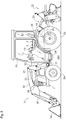
- Fig. 2 is a side view of a tractor that is an example of the work vehicle.
- the tractor has a vehicle body 1 supported by front wheels 2a and rear wheels 2b, an engine 20 mounted in a front portion of the vehicle body 1, and a transmission 24 mounted rearward of the engine 20.
- a rotary tiller 22 is mounted toward the rear of the vehicle body 1 as a work apparatus, with the rotary tiller 22 being mounted so as to be movable in a vertical direction via a lift mechanism 23.
- the tractor is a four-wheel-drive vehicle and motive force of the engine 20 is transmitted, via a speed change mechanism installed in the transmission 24, to the rear wheels 2b and front wheels 2a, which are capable of acting as drive wheels. Further, the power of the engine 20 is also transmitted to the rotary tiller 22 via a PTO shaft 25 that protrudes rearward from the transmission 24.
- the engine 20 is covered by a hood 21.
- a cabin 10 is supported on the vehicle body 1 to the rear of the hood 21 and above the transmission 24.
- a front loader 3 is provided in front of the vehicle body 1 so as to straddle the hood 21.
- the front loader 3 and the rotary tiller 22 need not provided together to a work vehicle, and only one of them can be provided at one time.
- Fig. 2 shows a tractor having both the front loader 3 and the rotary tiller 22 together.
- a pair of left/right masts 31 is attached to the vehicle body 1 on both left and right sides of the rear section of the hood 21.
- the body of the front loader 3 is attached to the left/right masts 31.
- the body of the front loader 3 is configured with a pair of left/right side frames 32 and a pair of left/right booms 33, with the left/right side frames 32 being attached to the respective left/right masts 31, and with the pair of left/right booms 33 being pivotally supported and coupled to an upper section of the respective left/right side frames 32 and being supported in a vertically swingable manner.
- a bucket 34 is pivotally supported and coupled in a vertically swingable manner.
- the front loader 3 is provided with boom cylinders 35 that vertically pivot the booms 3, and bucket cylinders 36 that vertically pivot the bucket 34.
- the boom cylinders 35 and the bucket cylinders 36 are configured as hydraulic cylinders.
- the motive force of the engine 20 drives a hydraulic pump (not shown in the drawings), and hydraulic fluid pumped by this hydraulic pump is supplied to an external hydraulic operation device via a hydraulic valve group 26.
- the hydraulic valve group 26 includes, in the rear section of the vehicle 1, a first hydraulic valve 261, a second hydraulic valve 262, a third hydraulic valve 263, a fourth hydraulic valve 264, a fifth hydraulic valve (not shown in the drawings), and a sixth hydraulic valve (not shown in the drawings). Further, the hydraulic valve group 26 also includes a hydraulic valve unit 260 for the front loader 3, with the hydraulic valve unit 260 being provided on a front bottom end of the cabin 10 of the vehicle body 1.
- the hydraulic valve unit 260 is configured to operate the boom cylinders 35 and the bucket cylinders 36 according to an operation of the driver.
- An interior of the cabin 10 serves as a driver space, at a front portion of which is arranged a steering handle or steering wheel 11 steering the front wheels 2a and at a rear portion of which is arranged a driver seat 12, with the driver seat 12 being positioned between a left-right pair of rear wheel fenders 15.
- An armrest operation device functioning as the operation unit 4 having a multifunction operation tool 5, spans from a side of the driver seat 12 to a front side thereof. Accordingly, the operation unit 4 is referred to as an armrest operation device 4.
- a display 13 visually notifying the driver of various information is provided forward of the armrest operation device 4.
- the display 13 allows an input operation to be performed via a touch panel 13A (see Fig. 3 ) and can accept various operation inputs by the driver.
- the armrest operation device 4 includes an armrest bed 4A as a base, and can be divided in a plan view into a front region 4a, a middle region 4b and a rear region 4c.
- a cushioning armrest portion 4B on which an arm is rested is provided in the rear region 4c.
- the multifunction operation tool 5, described in detail hereafter, is located on substantially a left half of the front region 4a.
- a first operation switch group 9a and a second operation switch group 9b, forming part of operation switch groups 9, are located on substantially a right half of the front region 4a.
- a third operation switch group 9c, a fourth operation switch group 9d, and a fifth operation switch group 9e, also being part of the operation switch groups 9, are arranged in the middle region 4b.
- the operation switches of the operation switch groups 9 may have various forms such as a button, switch, dial, lever, joystick, or the like.
- the configuration explained using Figs. 1A - 1C can be applied to the fifth operation switch group 9e in the present embodiment.
- the first mounting base 41, the second mounting base 42, the third mounting base 43, and the fourth mounting base 44 are adjacently formed from right to left.
- the first single-operation tool 91 for the first hydraulic valve 261, the second single-operation tool 92 for the second hydraulic valve 262, the third single-operation tool 93 for the third hydraulic valve 263, and the fourth single-operation tool 94 for the fourth hydraulic valve 264 are respectively mounted. All of the single-operation tools in this example are formed as seesaw type switches.
- the armrest operation device 4 shown in Fig. 3 has a basic configuration shown in Fig. 1B .
- the multifunction operation tool 5 is arranged in a front end area on the left side of the armrest bed 4A and is swingably supported around a swing axis P1.
- the multifunction operation tool 5 is substantially configured by a grip main body 5A and a swing body 5B.
- the swing body 5B is formed as an arm member pivoting around the swing axis P1.
- the vehicle is structured to accelerate by swinging the swing body 5B in a forward direction (UP) (upshift) from a swing neutral position of the swing body 5B, and to decelerate by swinging the swing body 5B in a backward direction (DOWN) (downshift).
- UP forward direction
- DOWN backward direction
- the grip main body 5A is provided on a free or upper end side of the swing body 5B. As shown in Fig. 4 , the grip main body 5A includes a grip portion 50 formed in a right-side region (here, substantially a right half region) and an elongated portion 51 formed in a left half region. A tab projecting outward is formed on at least a portion of a bottom edge of the grip portion 50 and functions as a hypothenar rest 55.
- the operation switch group 500 capable of being operated by fingers of a hand holding the grip portion 50 is arranged on the grip main body 5A.
- the operation switch group 500 includes a forward/reverse button 501, a lift/lower button 502, and two switches 507 and 508 controlling the fifth and sixth hydraulic valves (not shown in the drawings) configuring the hydraulic valve group 26. These switches 507 and 508 are also formed as seesaw type switches.
- the lift/lower button 502 acts as an elevation control tool lifting/lowering the rotary tiller 22 as a work apparatus. Pressing an upper portion 502a of the lift/lower button 502 raises the rotary tiller 22, whereas pressing a lower portion 502b of the lift/lower button 502 lowers the rotary tiller 22.
- Switching (shift up, shift down) of a speed change stage in the transmission 24 is performed by a swinging operation around the swing axis P1 of the grip part 50.
- the tractor By pressing an upward arrow of the forward/reverse button 501, the tractor is switched to a forward travel state, and by pressing a downward arrow of the forward/reverse button 501, the tractor is switched to a reverse travel state.
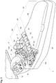
- the armrest operation device 4 can be of the type shown in Fig. 5 and which can have a basic configuration shown in Fig. 1C .
- the armrest operation device 4 is employed when the front loader 3 is provided.
- this armrest operation device 4 (shown in Fig. 5 ) differs only in the configuration of the fifth operation switch group 9e. Therefore, only the difference of the configuration is explained below.
- Spanning the first mounting base 41 and the second mounting base 42, one joystick type operation tool is mounted as the multi-operation tool 90.
- This joystick type tool includes a joystick body 900 extending upward from a mounting plate 90A.
- the joystick body 900 has a rounded stick body pivoting about an X axis and a Y axis.
- a first fingertip operation tool 901 is formed as a push button on the top of the joystick body 900
- a second fingertip operation tool 902 is formed as a dial switch on a side of the joystick body 900.
- the use of the first fingertip operation tool 901 and the second fingertip operation tool 902 is optional.
- these fingertip operation tools can be assigned as tools to store information such as an elevation location of the bucket 34.
- An operation input signal generated by operating the multi-operation tool 90 is input to the controller (see Fig. 7 ), and the front loader 3 is caused to operate via the hydraulic valve unit 260 for the front loader.
- the hydraulic valve unit 260 for the front loader is hereafter referred to simply as the hydraulic valve unit 260.
- the multi-operation tool 90 is a joystick type operation tool capable of causing X axis and Y axis operational displacement, one operational displacement can be assigned to the first hydraulic valve 261, and the other operational displacement can be assigned to the second hydraulic valve 262.
- the multi-operation tool 90 may be used for operating, for example, the first hydraulic valve 261 and the second hydraulic valve 262 (two hydraulic valves belonging to the hydraulic valve group 26 to the rear of the tractor) (i.e., "hydraulic valve mode control").
- the mounting plate 90A is provided with a mode selection button 903 that makes a selection between the front loader mode control and the hydraulic valve mode control.
- This mode selection button 903 is an alternate operational type, which selects the front loader mode control by one push, and selects the hydraulic valve mode control by a second push.
- a first mode lamp 904 is illuminated
- a second mode lamp 905 is illuminated.
- the mounting plate 90A is further provided with a lever lock button 906 which makes a selection between lever locking and lever unlocking.
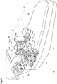
- Fig. 6 illustrates a multi-operation tool 90 according to another embodiment, which can span the first mounting base 41 and the second mounting base 42.
- This multi-operation tool 90 is also a joystick-type tool.
- a joystick body 920 of the multi-operation tool 90 illustrated in Fig. 6 is more ergonomic, and has a shape easier to grip.
- the joystick body 920 includes a hypothenar rest 921 on the lower end thereof, the hypothenar rest 921 used for resting a hypothenar of a hand gripping the joystick body 920. Similar to the joystick body 900 previously discussed, this joystick body 920 also includes the first fingertip operation tool 901 and the second fingertip operation tool 902.
- a control system equipped on the tractor is illustrated in the form of a functional block diagram.
- Examples of this control system include, in relation to the present embodiment, the controller 100, a device control unit 801, an input signal processor unit 802, and a notification processor unit 803 that are mutually connected so as to transmit data through a LAN installed to the vehicle.
- This illustrated configuration is merely for explanatory purposes. For a construction of an actual control system, arbitrary division or integration is possible.
- the device control unit 801 controls operation of the controllers for the engine 20, hydraulic device for the transmission 24, and the hydraulic valve group 26 (units 260 - 264, supplying hydraulic pressure to the work apparatus 22 provided to the rear of the tractor, e.g., rotary tiller, or to the front loader 3 provide to the front of the tractor), by sending operation signals generated based on the control signals from the controller 100.
- the input signal processor unit 802 is an input interface, inputting signals from the multifunction operation tool 5, the operation switch groups 9, and a group of status detection sensors SG (configured with various sensors) and transferring the input signals to various portions of the control system.
- the notification processor unit 803 is an input/output interface, processing image signals output to the display 13, audio signals output to a speaker 14, or operation input signals from the touch panel 13A.
- the controller 100 includes, as portions to realize various functions mainly by computer programs, a travel controller unit 6, a work controller unit 7, and a display controller unit 8.
- the travel controller unit 6 outputs via the device control unit 801 a speed change control command to a main speed change device and an auxiliary speed change device that configure the transmission 24 and creates a desired vehicle speed change ratio due to a combination of speed change stages of the main speed change device and the auxiliary speed change device.
- the display controller unit 8 transmits various screen data that is generated to the notification processor unit 803. Accordingly, a desired screen is displayed on the display 13.
- the screen displayed on the display 13 includes a screen for guiding/warning the driver based on signals from the group of status detection sensors SG, and a screen for assisting the driver by displaying statuses such as engine revolutions, speed change stage, vehicle speed, and hydraulic devices.
- the work controller unit 7 includes a hydraulic control manager 70, a valve mode controller 72, and a loader mode controller 71.
- the hydraulic control manager 70 generates control signals for controlling the work apparatus 22 (including the lift mechanism 23) or the front loader 3, based on the signals transmitted via the input signal processor unit 802 from the multifunction operation tool 5 and the operation switch groups 9 (arranged on the armrest operation device 4).
- the multi-operation tool 90 may be configured to operate the first hydraulic valve 261 and the second hydraulic valve 262, similar to the first single-operation tool 91 and the second single-operation tool 92, with the multi-operation tool 90 being provided as a joystick type operation tool instead of the first single-operation tool 91 and the second single-operation tool 92.
- This selection can be made by pressing the mode selection button 903, which causes the valve mode controller 72 to operate.
- the loader mode controller 71 is operated.
- the valve mode controller 72 performs hydraulic valve mode control that controls the first hydraulic valve 261 and the second hydraulic valve 262 based on the operation input signals from the multi-operation tool (joystick type operation tool) 90.
- the loader mode controller 71 controls the hydraulic valve unit 260 based on the operation input signals from the same multi-operation tool 90, and, as a result, performs front loader mode control controlling the front loader 3.
- the operation control system according to the present embodiment may be applied to a work vehicle that can accommodate various work apparatuses interchangeably equipped to the vehicle body, such as a tractor.
Landscapes
- Engineering & Computer Science (AREA)
- Physics & Mathematics (AREA)
- Mechanical Engineering (AREA)
- Fluid Mechanics (AREA)
- General Engineering & Computer Science (AREA)
- Automation & Control Theory (AREA)
- General Physics & Mathematics (AREA)
- Chemical & Material Sciences (AREA)
- Combustion & Propulsion (AREA)
- Transportation (AREA)
- Operation Control Of Excavators (AREA)
- Component Parts Of Construction Machinery (AREA)
- Lifting Devices For Agricultural Implements (AREA)
- Mechanical Control Devices (AREA)
Claims (7)
- Système de commande de fonctionnement destiné à être installé sur un véhicule de chantier sur lequel est prévu ou monté un outil de travail (22), comprenant :un dispositif de commande (100) prévu pour commander l'outil de travail (22) ;une première soupape hydraulique (261) et une deuxième soupape hydraulique (262) prévues pour commander l'alimentation en pression hydraulique de l'outil de travail (22) ; etune unité de commande (4) prévue pour transmettre un signal d'entrée de fonctionnement au dispositif de commande ;caractérisé en ce quel'unité de commande (4) comporte une première base de montage (41) et une deuxième base de montage (42) adjacentes l'une à l'autre, un premier outil à fonction simple (91), un deuxième outil à fonction simple (92) et un outil multifonctionnel (90) ;le premier outil à fonction simple, le deuxième outil à fonction simple et l'outil multifonctionnel sont prévus pour commander la première et la deuxième soupapes hydrauliques ;la première base de montage, la deuxième base de montage, le premier outil à fonction simple, le deuxième outil à fonction simple et l'outil multifonctionnel sont prévus de sorte :que la première base de montage (41) est adaptée pour recevoir le premier outil à fonction simple (91) ;la deuxième base de montage (42) est adaptée pour recevoir le deuxième outil à fonction simple (92) ; etla première base de montage (41) et la deuxième base de montage (42) sont adaptées pour recevoir ensemble l'outil multifonctionnel (90) sur la première base de montage et la deuxième base de montage.
- Système de commande de fonctionnement selon la revendication 1, où
l'outil multifonctionnel est prévu de sorte que le mouvement de l'outil multifonctionnel le long d'un axe génère un signal de commande via la première base de montage, et que le mouvement de l'outil multifonctionnel le long d'un autre axe génère un signal de commande via la deuxième base de montage. - Système de commande de fonctionnement selon la revendication 2, où
l'outil multifonctionnel est prévu de sorte que le mouvement de l'outil multifonctionnel le long d'un axe transmet un signal au dispositif de commande via la première base de montage et que le mouvement de l'outil multifonctionnel le long d'un autre axe transmet un signal au dispositif de commande via la deuxième base de montage. - Système de commande de fonctionnement selon la revendication 1, la revendication 2 ou la revendication 3, où l'outil multifonctionnel est un joystick.
- Système de commande de fonctionnement selon l'une des revendications 1 à 4, où
le dispositif de commande comprend un dispositif de commande de mode de soupape prévu pour exécuter une commande de mode de soupape hydraulique permettant de commander la première soupape hydraulique et la deuxième soupape hydraulique sur la base du signal d'entrée de fonctionnement. - Système de commande de fonctionnement selon l'une des revendications 1 à 5, où
le dispositif de commande comprend un dispositif de commande de mode de chargeur prévu pour exécuter une commande de mode de chargeur frontal permettant de commander un chargeur frontal sur la base du signal d'entrée de fonctionnement via une unité de soupape hydraulique de chargeur frontal. - Système de commande de fonctionnement selon l'une des revendications 1 à 6, où
l'outil multifonctionnel comprend :un dispositif de sélection de mode hydraulique monté sur celui-ci ; et/ouun commutateur de sélection prévu pour commuter entre une commande de mode de soupape hydraulique et une commande de mode de chargeur frontal.
Applications Claiming Priority (1)
| Application Number | Priority Date | Filing Date | Title |
|---|---|---|---|
| JP2014166538A JP6234342B2 (ja) | 2014-08-19 | 2014-08-19 | 操作制御システム |
Publications (2)
| Publication Number | Publication Date |
|---|---|
| EP2987672A1 EP2987672A1 (fr) | 2016-02-24 |
| EP2987672B1 true EP2987672B1 (fr) | 2018-11-07 |
Family
ID=54140203
Family Applications (1)
| Application Number | Title | Priority Date | Filing Date |
|---|---|---|---|
| EP15181614.7A Active EP2987672B1 (fr) | 2014-08-19 | 2015-08-19 | Système de contrôle |
Country Status (3)
| Country | Link |
|---|---|
| US (1) | US9670939B2 (fr) |
| EP (1) | EP2987672B1 (fr) |
| JP (1) | JP6234342B2 (fr) |
Families Citing this family (22)
| Publication number | Priority date | Publication date | Assignee | Title |
|---|---|---|---|---|
| EP3032371A4 (fr) * | 2013-08-09 | 2017-05-31 | Yanmar Co., Ltd. | Véhicule de travail |
| JP6247174B2 (ja) * | 2014-08-01 | 2017-12-13 | 株式会社クボタ | 運転支援システム |
| WO2017006592A1 (fr) * | 2015-07-07 | 2017-01-12 | ヤンマー株式会社 | Tracteur |
| BR112018014057A2 (pt) | 2016-02-05 | 2018-12-11 | Crown Equip Corp | ?módulo e elemento de controle para controlar pelo menos uma função de um veículo de manuseio de materiais? |
| US10174485B2 (en) * | 2016-11-23 | 2019-01-08 | Cnh Industrial America Llc | System and method for providing reconfigurable input devices for a work vehicle |
| DE102017003193A1 (de) * | 2017-04-01 | 2018-10-04 | Man Truck & Bus Ag | Vorrichtung, insbesondere zum Einbau in ein Kraftfahrzeug, mit einem Aufnahmeschacht |
| WO2019124298A1 (fr) * | 2017-12-18 | 2019-06-27 | 株式会社クボタ | Véhicule de travail et tracteur |
| GB201721502D0 (en) | 2017-12-20 | 2018-01-31 | Agco Int Gmbh | Agricultural vehicle |
| JP6946173B2 (ja) * | 2017-12-27 | 2021-10-06 | 株式会社クボタ | 作業機 |
| EP3656932A4 (fr) * | 2017-12-27 | 2021-05-12 | Kubota Corporation | Équipement de travail et son procédé de production |
| JP6946172B2 (ja) * | 2017-12-27 | 2021-10-06 | 株式会社クボタ | 作業機 |
| EP3744161A4 (fr) | 2018-01-23 | 2022-01-12 | Kubota Corporation | Véhicule de travail |
| JP7290923B2 (ja) * | 2018-07-11 | 2023-06-14 | 株式会社クボタ | 作業車両 |
| JP6961544B2 (ja) * | 2018-06-29 | 2021-11-05 | 株式会社クボタ | 作業機 |
| WO2020003948A1 (fr) * | 2018-06-29 | 2020-01-02 | 株式会社クボタ | Machine de travail |
| USD944869S1 (en) | 2018-09-07 | 2022-03-01 | Crown Equipment Corporation | Arm pad |
| USD944868S1 (en) | 2018-09-07 | 2022-03-01 | Crown Equipment Corporation | Arm pad |
| USD922279S1 (en) | 2018-10-17 | 2021-06-15 | Crown Equipment Corporation | Control pod |
| EP3663128B1 (fr) | 2018-12-06 | 2023-10-04 | Kubota Corporation | Véhicule de travail |
| JP7433845B2 (ja) * | 2018-12-06 | 2024-02-20 | 株式会社クボタ | 作業車両 |
| JP7275006B2 (ja) * | 2019-11-08 | 2023-05-17 | 株式会社クボタ | 作業車両 |
| JP7275007B2 (ja) * | 2019-11-08 | 2023-05-17 | 株式会社クボタ | 作業車両 |
Family Cites Families (8)
| Publication number | Priority date | Publication date | Assignee | Title |
|---|---|---|---|---|
| JP2945578B2 (ja) * | 1994-06-06 | 1999-09-06 | 株式会社クボタ | 刈取作業機の昇降装置 |
| DE10341283A1 (de) * | 2003-09-08 | 2005-03-31 | Robert Bosch Gmbh | Fahrzeugsystem mit austauschbar anordenbaren Bedieneinrichtungsmodulen |
| US7178623B2 (en) * | 2003-12-19 | 2007-02-20 | Caterpillar Inc | Operator control assembly |
| JP4570510B2 (ja) | 2005-04-27 | 2010-10-27 | 株式会社クボタ | トラクタ |
| JP2007092284A (ja) | 2005-09-26 | 2007-04-12 | Kubota Corp | 作業車 |
| US7712571B2 (en) * | 2006-06-23 | 2010-05-11 | Caterpillar Inc. | Ergonomic machine control console |
| GB201113697D0 (en) * | 2011-08-09 | 2011-09-21 | Agco Int Gmbh | Control means for controlling an implement attached to a vehicle |
| JP2014166815A (ja) * | 2013-02-28 | 2014-09-11 | Iseki & Co Ltd | 作業車 |
-
2014
- 2014-08-19 JP JP2014166538A patent/JP6234342B2/ja active Active
-
2015
- 2015-08-17 US US14/827,569 patent/US9670939B2/en active Active
- 2015-08-19 EP EP15181614.7A patent/EP2987672B1/fr active Active
Non-Patent Citations (1)
| Title |
|---|
| None * |
Also Published As
| Publication number | Publication date |
|---|---|
| JP2016041565A (ja) | 2016-03-31 |
| US9670939B2 (en) | 2017-06-06 |
| EP2987672A1 (fr) | 2016-02-24 |
| US20160053779A1 (en) | 2016-02-25 |
| JP6234342B2 (ja) | 2017-11-22 |
Similar Documents
| Publication | Publication Date | Title |
|---|---|---|
| EP2987672B1 (fr) | Système de contrôle | |
| EP1346268B1 (fr) | Poignee a microprocesseur permettant de commander une machine a moteur | |
| EP2980317A1 (fr) | Multiples modèles de commande pour machines hydraulique à commandes à la main et au pied | |
| US8392075B2 (en) | Carrier and backhoe control system and method | |
| US10302027B2 (en) | Variable engine speed control | |
| CN103850285B (zh) | 用于行驶控制启用的方法和设备 | |
| US6293033B1 (en) | Construction machinery | |
| US4645030A (en) | Multi-function directional handle | |
| US20060064221A1 (en) | Operator selectable control pattern | |
| US5235811A (en) | Control change system for a hydraulic work vehicle | |
| EP3704314B1 (fr) | Ascenseur d'excavatrice | |
| KR20010034295A (ko) | 건설기계 | |
| US11686066B2 (en) | Working machine joystick assembly | |
| EP4083333A2 (fr) | Manette multifonction avec poignée asymétrique pour une machine de construction | |
| JPH08270017A (ja) | 作業機の操作レバー及びブルドーザ | |
| JP3839364B2 (ja) | 建設機械のコンソールボックス | |
| JPH09156875A (ja) | 建設機械の油圧制御装置 | |
| EP4265850A1 (fr) | Machine de construction | |
| EP2212755B1 (fr) | Levier de commande pour faire fonctionner une machine, procédé pour faire fonctionner une machine par l'intermédiaire d'un levier de commande et utilisation du levier de commande | |
| KR101877059B1 (ko) | 건설기계의 제어장치 | |
| JPH0522498U (ja) | 産業車両の作業機操作装置 | |
| CN112302067A (zh) | 用于操作施工机械的机械控制系统 |
Legal Events
| Date | Code | Title | Description |
|---|---|---|---|
| PUAI | Public reference made under article 153(3) epc to a published international application that has entered the european phase |
Free format text: ORIGINAL CODE: 0009012 |
|
| AK | Designated contracting states |
Kind code of ref document: A1 Designated state(s): AL AT BE BG CH CY CZ DE DK EE ES FI FR GB GR HR HU IE IS IT LI LT LU LV MC MK MT NL NO PL PT RO RS SE SI SK SM TR |
|
| AX | Request for extension of the european patent |
Extension state: BA ME |
|
| 17P | Request for examination filed |
Effective date: 20160930 |
|
| RBV | Designated contracting states (corrected) |
Designated state(s): AL AT BE BG CH CY CZ DE DK EE ES FI FR GB GR HR HU IE IS IT LI LT LU LV MC MK MT NL NO PL PT RO RS SE SI SK SM TR |
|
| RIC1 | Information provided on ipc code assigned before grant |
Ipc: F15B 13/06 20060101ALI20180612BHEP Ipc: F15B 13/14 20060101ALI20180612BHEP Ipc: G05G 9/047 20060101ALI20180612BHEP Ipc: B60K 37/06 20060101AFI20180612BHEP Ipc: F15B 11/16 20060101ALI20180612BHEP |
|
| GRAP | Despatch of communication of intention to grant a patent |
Free format text: ORIGINAL CODE: EPIDOSNIGR1 |
|
| STAA | Information on the status of an ep patent application or granted ep patent |
Free format text: STATUS: GRANT OF PATENT IS INTENDED |
|
| GRAS | Grant fee paid |
Free format text: ORIGINAL CODE: EPIDOSNIGR3 |
|
| GRAJ | Information related to disapproval of communication of intention to grant by the applicant or resumption of examination proceedings by the epo deleted |
Free format text: ORIGINAL CODE: EPIDOSDIGR1 |
|
| GRAL | Information related to payment of fee for publishing/printing deleted |
Free format text: ORIGINAL CODE: EPIDOSDIGR3 |
|
| INTG | Intention to grant announced |
Effective date: 20180730 |
|
| STAA | Information on the status of an ep patent application or granted ep patent |
Free format text: STATUS: REQUEST FOR EXAMINATION WAS MADE |
|
| GRAR | Information related to intention to grant a patent recorded |
Free format text: ORIGINAL CODE: EPIDOSNIGR71 |
|
| STAA | Information on the status of an ep patent application or granted ep patent |
Free format text: STATUS: GRANT OF PATENT IS INTENDED |
|
| INTC | Intention to grant announced (deleted) | ||
| GRAA | (expected) grant |
Free format text: ORIGINAL CODE: 0009210 |
|
| STAA | Information on the status of an ep patent application or granted ep patent |
Free format text: STATUS: THE PATENT HAS BEEN GRANTED |
|
| INTG | Intention to grant announced |
Effective date: 20180927 |
|
| AK | Designated contracting states |
Kind code of ref document: B1 Designated state(s): AL AT BE BG CH CY CZ DE DK EE ES FI FR GB GR HR HU IE IS IT LI LT LU LV MC MK MT NL NO PL PT RO RS SE SI SK SM TR |
|
| REG | Reference to a national code |
Ref country code: GB Ref legal event code: FG4D |
|
| REG | Reference to a national code |
Ref country code: CH Ref legal event code: EP Ref country code: AT Ref legal event code: REF Ref document number: 1061640 Country of ref document: AT Kind code of ref document: T Effective date: 20181115 |
|
| REG | Reference to a national code |
Ref country code: DE Ref legal event code: R096 Ref document number: 602015019394 Country of ref document: DE |
|
| REG | Reference to a national code |
Ref country code: IE Ref legal event code: FG4D |
|
| REG | Reference to a national code |
Ref country code: NL Ref legal event code: MP Effective date: 20181107 |
|
| REG | Reference to a national code |
Ref country code: LT Ref legal event code: MG4D |
|
| REG | Reference to a national code |
Ref country code: AT Ref legal event code: MK05 Ref document number: 1061640 Country of ref document: AT Kind code of ref document: T Effective date: 20181107 |
|
| PG25 | Lapsed in a contracting state [announced via postgrant information from national office to epo] |
Ref country code: BG Free format text: LAPSE BECAUSE OF FAILURE TO SUBMIT A TRANSLATION OF THE DESCRIPTION OR TO PAY THE FEE WITHIN THE PRESCRIBED TIME-LIMIT Effective date: 20190207 Ref country code: IS Free format text: LAPSE BECAUSE OF FAILURE TO SUBMIT A TRANSLATION OF THE DESCRIPTION OR TO PAY THE FEE WITHIN THE PRESCRIBED TIME-LIMIT Effective date: 20190307 Ref country code: HR Free format text: LAPSE BECAUSE OF FAILURE TO SUBMIT A TRANSLATION OF THE DESCRIPTION OR TO PAY THE FEE WITHIN THE PRESCRIBED TIME-LIMIT Effective date: 20181107 Ref country code: NO Free format text: LAPSE BECAUSE OF FAILURE TO SUBMIT A TRANSLATION OF THE DESCRIPTION OR TO PAY THE FEE WITHIN THE PRESCRIBED TIME-LIMIT Effective date: 20190207 Ref country code: AT Free format text: LAPSE BECAUSE OF FAILURE TO SUBMIT A TRANSLATION OF THE DESCRIPTION OR TO PAY THE FEE WITHIN THE PRESCRIBED TIME-LIMIT Effective date: 20181107 Ref country code: LV Free format text: LAPSE BECAUSE OF FAILURE TO SUBMIT A TRANSLATION OF THE DESCRIPTION OR TO PAY THE FEE WITHIN THE PRESCRIBED TIME-LIMIT Effective date: 20181107 Ref country code: FI Free format text: LAPSE BECAUSE OF FAILURE TO SUBMIT A TRANSLATION OF THE DESCRIPTION OR TO PAY THE FEE WITHIN THE PRESCRIBED TIME-LIMIT Effective date: 20181107 Ref country code: LT Free format text: LAPSE BECAUSE OF FAILURE TO SUBMIT A TRANSLATION OF THE DESCRIPTION OR TO PAY THE FEE WITHIN THE PRESCRIBED TIME-LIMIT Effective date: 20181107 Ref country code: ES Free format text: LAPSE BECAUSE OF FAILURE TO SUBMIT A TRANSLATION OF THE DESCRIPTION OR TO PAY THE FEE WITHIN THE PRESCRIBED TIME-LIMIT Effective date: 20181107 |
|
| PG25 | Lapsed in a contracting state [announced via postgrant information from national office to epo] |
Ref country code: PT Free format text: LAPSE BECAUSE OF FAILURE TO SUBMIT A TRANSLATION OF THE DESCRIPTION OR TO PAY THE FEE WITHIN THE PRESCRIBED TIME-LIMIT Effective date: 20190307 Ref country code: SE Free format text: LAPSE BECAUSE OF FAILURE TO SUBMIT A TRANSLATION OF THE DESCRIPTION OR TO PAY THE FEE WITHIN THE PRESCRIBED TIME-LIMIT Effective date: 20181107 Ref country code: NL Free format text: LAPSE BECAUSE OF FAILURE TO SUBMIT A TRANSLATION OF THE DESCRIPTION OR TO PAY THE FEE WITHIN THE PRESCRIBED TIME-LIMIT Effective date: 20181107 Ref country code: GR Free format text: LAPSE BECAUSE OF FAILURE TO SUBMIT A TRANSLATION OF THE DESCRIPTION OR TO PAY THE FEE WITHIN THE PRESCRIBED TIME-LIMIT Effective date: 20190208 Ref country code: AL Free format text: LAPSE BECAUSE OF FAILURE TO SUBMIT A TRANSLATION OF THE DESCRIPTION OR TO PAY THE FEE WITHIN THE PRESCRIBED TIME-LIMIT Effective date: 20181107 Ref country code: RS Free format text: LAPSE BECAUSE OF FAILURE TO SUBMIT A TRANSLATION OF THE DESCRIPTION OR TO PAY THE FEE WITHIN THE PRESCRIBED TIME-LIMIT Effective date: 20181107 |
|
| PG25 | Lapsed in a contracting state [announced via postgrant information from national office to epo] |
Ref country code: CZ Free format text: LAPSE BECAUSE OF FAILURE TO SUBMIT A TRANSLATION OF THE DESCRIPTION OR TO PAY THE FEE WITHIN THE PRESCRIBED TIME-LIMIT Effective date: 20181107 Ref country code: PL Free format text: LAPSE BECAUSE OF FAILURE TO SUBMIT A TRANSLATION OF THE DESCRIPTION OR TO PAY THE FEE WITHIN THE PRESCRIBED TIME-LIMIT Effective date: 20181107 Ref country code: DK Free format text: LAPSE BECAUSE OF FAILURE TO SUBMIT A TRANSLATION OF THE DESCRIPTION OR TO PAY THE FEE WITHIN THE PRESCRIBED TIME-LIMIT Effective date: 20181107 Ref country code: IT Free format text: LAPSE BECAUSE OF FAILURE TO SUBMIT A TRANSLATION OF THE DESCRIPTION OR TO PAY THE FEE WITHIN THE PRESCRIBED TIME-LIMIT Effective date: 20181107 |
|
| REG | Reference to a national code |
Ref country code: DE Ref legal event code: R097 Ref document number: 602015019394 Country of ref document: DE |
|
| PG25 | Lapsed in a contracting state [announced via postgrant information from national office to epo] |
Ref country code: EE Free format text: LAPSE BECAUSE OF FAILURE TO SUBMIT A TRANSLATION OF THE DESCRIPTION OR TO PAY THE FEE WITHIN THE PRESCRIBED TIME-LIMIT Effective date: 20181107 Ref country code: SM Free format text: LAPSE BECAUSE OF FAILURE TO SUBMIT A TRANSLATION OF THE DESCRIPTION OR TO PAY THE FEE WITHIN THE PRESCRIBED TIME-LIMIT Effective date: 20181107 Ref country code: RO Free format text: LAPSE BECAUSE OF FAILURE TO SUBMIT A TRANSLATION OF THE DESCRIPTION OR TO PAY THE FEE WITHIN THE PRESCRIBED TIME-LIMIT Effective date: 20181107 Ref country code: SK Free format text: LAPSE BECAUSE OF FAILURE TO SUBMIT A TRANSLATION OF THE DESCRIPTION OR TO PAY THE FEE WITHIN THE PRESCRIBED TIME-LIMIT Effective date: 20181107 |
|
| PLBE | No opposition filed within time limit |
Free format text: ORIGINAL CODE: 0009261 |
|
| STAA | Information on the status of an ep patent application or granted ep patent |
Free format text: STATUS: NO OPPOSITION FILED WITHIN TIME LIMIT |
|
| 26N | No opposition filed |
Effective date: 20190808 |
|
| PG25 | Lapsed in a contracting state [announced via postgrant information from national office to epo] |
Ref country code: SI Free format text: LAPSE BECAUSE OF FAILURE TO SUBMIT A TRANSLATION OF THE DESCRIPTION OR TO PAY THE FEE WITHIN THE PRESCRIBED TIME-LIMIT Effective date: 20181107 |
|
| PG25 | Lapsed in a contracting state [announced via postgrant information from national office to epo] |
Ref country code: TR Free format text: LAPSE BECAUSE OF FAILURE TO SUBMIT A TRANSLATION OF THE DESCRIPTION OR TO PAY THE FEE WITHIN THE PRESCRIBED TIME-LIMIT Effective date: 20181107 |
|
| GBPC | Gb: european patent ceased through non-payment of renewal fee |
Effective date: 20190819 |
|
| PG25 | Lapsed in a contracting state [announced via postgrant information from national office to epo] |
Ref country code: CH Free format text: LAPSE BECAUSE OF NON-PAYMENT OF DUE FEES Effective date: 20190831 Ref country code: LU Free format text: LAPSE BECAUSE OF NON-PAYMENT OF DUE FEES Effective date: 20190819 Ref country code: LI Free format text: LAPSE BECAUSE OF NON-PAYMENT OF DUE FEES Effective date: 20190831 Ref country code: MC Free format text: LAPSE BECAUSE OF FAILURE TO SUBMIT A TRANSLATION OF THE DESCRIPTION OR TO PAY THE FEE WITHIN THE PRESCRIBED TIME-LIMIT Effective date: 20181107 |
|
| REG | Reference to a national code |
Ref country code: BE Ref legal event code: MM Effective date: 20190831 |
|
| PG25 | Lapsed in a contracting state [announced via postgrant information from national office to epo] |
Ref country code: IE Free format text: LAPSE BECAUSE OF NON-PAYMENT OF DUE FEES Effective date: 20190819 |
|
| PG25 | Lapsed in a contracting state [announced via postgrant information from national office to epo] |
Ref country code: BE Free format text: LAPSE BECAUSE OF NON-PAYMENT OF DUE FEES Effective date: 20190831 Ref country code: GB Free format text: LAPSE BECAUSE OF NON-PAYMENT OF DUE FEES Effective date: 20190819 |
|
| PG25 | Lapsed in a contracting state [announced via postgrant information from national office to epo] |
Ref country code: CY Free format text: LAPSE BECAUSE OF FAILURE TO SUBMIT A TRANSLATION OF THE DESCRIPTION OR TO PAY THE FEE WITHIN THE PRESCRIBED TIME-LIMIT Effective date: 20181107 |
|
| PG25 | Lapsed in a contracting state [announced via postgrant information from national office to epo] |
Ref country code: MT Free format text: LAPSE BECAUSE OF FAILURE TO SUBMIT A TRANSLATION OF THE DESCRIPTION OR TO PAY THE FEE WITHIN THE PRESCRIBED TIME-LIMIT Effective date: 20181107 Ref country code: HU Free format text: LAPSE BECAUSE OF FAILURE TO SUBMIT A TRANSLATION OF THE DESCRIPTION OR TO PAY THE FEE WITHIN THE PRESCRIBED TIME-LIMIT; INVALID AB INITIO Effective date: 20150819 |
|
| PG25 | Lapsed in a contracting state [announced via postgrant information from national office to epo] |
Ref country code: MK Free format text: LAPSE BECAUSE OF FAILURE TO SUBMIT A TRANSLATION OF THE DESCRIPTION OR TO PAY THE FEE WITHIN THE PRESCRIBED TIME-LIMIT Effective date: 20181107 |
|
| REG | Reference to a national code |
Ref country code: DE Ref legal event code: R079 Ref document number: 602015019394 Country of ref document: DE Free format text: PREVIOUS MAIN CLASS: B60K0037060000 Ipc: B60K0035100000 |
|
| PGFP | Annual fee paid to national office [announced via postgrant information from national office to epo] |
Ref country code: FR Payment date: 20230703 Year of fee payment: 9 Ref country code: DE Payment date: 20230627 Year of fee payment: 9 |