EP2986892B1 - Beleuchtungsvorrichtungen mit einstellbaren optischen elementen - Google Patents
Beleuchtungsvorrichtungen mit einstellbaren optischen elementen Download PDFInfo
- Publication number
- EP2986892B1 EP2986892B1 EP14731419.9A EP14731419A EP2986892B1 EP 2986892 B1 EP2986892 B1 EP 2986892B1 EP 14731419 A EP14731419 A EP 14731419A EP 2986892 B1 EP2986892 B1 EP 2986892B1
- Authority
- EP
- European Patent Office
- Prior art keywords
- light
- illumination device
- luminaire module
- lees
- adjustable illumination
- Prior art date
- Legal status (The legal status is an assumption and is not a legal conclusion. Google has not performed a legal analysis and makes no representation as to the accuracy of the status listed.)
- Active
Links
- 238000005286 illumination Methods 0.000 title claims description 225
- 230000003287 optical effect Effects 0.000 title description 23
- 239000000463 material Substances 0.000 description 33
- 238000009826 distribution Methods 0.000 description 26
- 239000007787 solid Substances 0.000 description 16
- 238000000034 method Methods 0.000 description 8
- 238000006243 chemical reaction Methods 0.000 description 7
- 230000033001 locomotion Effects 0.000 description 6
- 230000007246 mechanism Effects 0.000 description 6
- 230000005540 biological transmission Effects 0.000 description 5
- 238000001228 spectrum Methods 0.000 description 5
- 230000004313 glare Effects 0.000 description 4
- 239000011521 glass Substances 0.000 description 4
- 239000000203 mixture Substances 0.000 description 4
- NIXOWILDQLNWCW-UHFFFAOYSA-N acrylic acid group Chemical group C(C=C)(=O)O NIXOWILDQLNWCW-UHFFFAOYSA-N 0.000 description 3
- 230000001419 dependent effect Effects 0.000 description 3
- 238000000295 emission spectrum Methods 0.000 description 3
- 239000004033 plastic Substances 0.000 description 3
- 239000004417 polycarbonate Substances 0.000 description 3
- 229920000515 polycarbonate Polymers 0.000 description 3
- 230000005855 radiation Effects 0.000 description 3
- 238000007493 shaping process Methods 0.000 description 3
- VYPSYNLAJGMNEJ-UHFFFAOYSA-N Silicium dioxide Chemical compound O=[Si]=O VYPSYNLAJGMNEJ-UHFFFAOYSA-N 0.000 description 2
- 239000000853 adhesive Substances 0.000 description 2
- 230000001070 adhesive effect Effects 0.000 description 2
- 229910052782 aluminium Inorganic materials 0.000 description 2
- XAGFODPZIPBFFR-UHFFFAOYSA-N aluminium Chemical compound [Al] XAGFODPZIPBFFR-UHFFFAOYSA-N 0.000 description 2
- 238000010586 diagram Methods 0.000 description 2
- 239000012530 fluid Substances 0.000 description 2
- 239000004519 grease Substances 0.000 description 2
- 229910052751 metal Inorganic materials 0.000 description 2
- 239000002184 metal Substances 0.000 description 2
- NJPPVKZQTLUDBO-UHFFFAOYSA-N novaluron Chemical compound C1=C(Cl)C(OC(F)(F)C(OC(F)(F)F)F)=CC=C1NC(=O)NC(=O)C1=C(F)C=CC=C1F NJPPVKZQTLUDBO-UHFFFAOYSA-N 0.000 description 2
- 230000036961 partial effect Effects 0.000 description 2
- 238000002310 reflectometry Methods 0.000 description 2
- 239000004065 semiconductor Substances 0.000 description 2
- 229910052709 silver Inorganic materials 0.000 description 2
- 239000004332 silver Substances 0.000 description 2
- 238000004088 simulation Methods 0.000 description 2
- DLMBMHOJKBPKLK-UHFFFAOYSA-N 3-(6-ethoxynaphthalen-2-yl)-1-(piperidin-4-ylmethyl)pyrazolo[3,4-d]pyrimidin-4-amine Chemical compound C1=CC2=CC(OCC)=CC=C2C=C1C(C1=C(N)N=CN=C11)=NN1CC1CCNCC1 DLMBMHOJKBPKLK-UHFFFAOYSA-N 0.000 description 1
- 239000005294 BK7 Substances 0.000 description 1
- 238000010521 absorption reaction Methods 0.000 description 1
- 230000004913 activation Effects 0.000 description 1
- 230000004075 alteration Effects 0.000 description 1
- 238000000149 argon plasma sintering Methods 0.000 description 1
- 230000000903 blocking effect Effects 0.000 description 1
- 239000011248 coating agent Substances 0.000 description 1
- 238000000576 coating method Methods 0.000 description 1
- 230000003247 decreasing effect Effects 0.000 description 1
- 239000003989 dielectric material Substances 0.000 description 1
- 239000005350 fused silica glass Substances 0.000 description 1
- 238000010438 heat treatment Methods 0.000 description 1
- 239000011261 inert gas Substances 0.000 description 1
- 238000003780 insertion Methods 0.000 description 1
- 230000037431 insertion Effects 0.000 description 1
- 230000000670 limiting effect Effects 0.000 description 1
- 230000013011 mating Effects 0.000 description 1
- 238000013041 optical simulation Methods 0.000 description 1
- 230000003647 oxidation Effects 0.000 description 1
- 238000007254 oxidation reaction Methods 0.000 description 1
- 229920000642 polymer Polymers 0.000 description 1
- 239000000843 powder Substances 0.000 description 1
- 230000008569 process Effects 0.000 description 1
- 239000011253 protective coating Substances 0.000 description 1
- 230000002829 reductive effect Effects 0.000 description 1
- 238000009420 retrofitting Methods 0.000 description 1
- 238000000926 separation method Methods 0.000 description 1
- 239000011343 solid material Substances 0.000 description 1
- 230000003595 spectral effect Effects 0.000 description 1
- 230000001360 synchronised effect Effects 0.000 description 1
- 239000012780 transparent material Substances 0.000 description 1
Images


Classifications
-
- F—MECHANICAL ENGINEERING; LIGHTING; HEATING; WEAPONS; BLASTING
- F21—LIGHTING
- F21V—FUNCTIONAL FEATURES OR DETAILS OF LIGHTING DEVICES OR SYSTEMS THEREOF; STRUCTURAL COMBINATIONS OF LIGHTING DEVICES WITH OTHER ARTICLES, NOT OTHERWISE PROVIDED FOR
- F21V19/00—Fastening of light sources or lamp holders
- F21V19/02—Fastening of light sources or lamp holders with provision for adjustment, e.g. for focusing
-
- F—MECHANICAL ENGINEERING; LIGHTING; HEATING; WEAPONS; BLASTING
- F21—LIGHTING
- F21K—NON-ELECTRIC LIGHT SOURCES USING LUMINESCENCE; LIGHT SOURCES USING ELECTROCHEMILUMINESCENCE; LIGHT SOURCES USING CHARGES OF COMBUSTIBLE MATERIAL; LIGHT SOURCES USING SEMICONDUCTOR DEVICES AS LIGHT-GENERATING ELEMENTS; LIGHT SOURCES NOT OTHERWISE PROVIDED FOR
- F21K9/00—Light sources using semiconductor devices as light-generating elements, e.g. using light-emitting diodes [LED] or lasers
- F21K9/20—Light sources comprising attachment means
- F21K9/23—Retrofit light sources for lighting devices with a single fitting for each light source, e.g. for substitution of incandescent lamps with bayonet or threaded fittings
-
- F—MECHANICAL ENGINEERING; LIGHTING; HEATING; WEAPONS; BLASTING
- F21—LIGHTING
- F21S—NON-PORTABLE LIGHTING DEVICES; SYSTEMS THEREOF; VEHICLE LIGHTING DEVICES SPECIALLY ADAPTED FOR VEHICLE EXTERIORS
- F21S6/00—Lighting devices intended to be free-standing
- F21S6/002—Table lamps, e.g. for ambient lighting
-
- F—MECHANICAL ENGINEERING; LIGHTING; HEATING; WEAPONS; BLASTING
- F21—LIGHTING
- F21S—NON-PORTABLE LIGHTING DEVICES; SYSTEMS THEREOF; VEHICLE LIGHTING DEVICES SPECIALLY ADAPTED FOR VEHICLE EXTERIORS
- F21S6/00—Lighting devices intended to be free-standing
- F21S6/005—Lighting devices intended to be free-standing with a lamp housing maintained at a distance from the floor or ground via a support, e.g. standing lamp for ambient lighting
- F21S6/007—Lighting devices intended to be free-standing with a lamp housing maintained at a distance from the floor or ground via a support, e.g. standing lamp for ambient lighting for indirect lighting only, e.g. torchiere with reflector bowl directed towards ceiling
-
- F—MECHANICAL ENGINEERING; LIGHTING; HEATING; WEAPONS; BLASTING
- F21—LIGHTING
- F21S—NON-PORTABLE LIGHTING DEVICES; SYSTEMS THEREOF; VEHICLE LIGHTING DEVICES SPECIALLY ADAPTED FOR VEHICLE EXTERIORS
- F21S8/00—Lighting devices intended for fixed installation
- F21S8/02—Lighting devices intended for fixed installation of recess-mounted type, e.g. downlighters
- F21S8/026—Lighting devices intended for fixed installation of recess-mounted type, e.g. downlighters intended to be recessed in a ceiling or like overhead structure, e.g. suspended ceiling
-
- F—MECHANICAL ENGINEERING; LIGHTING; HEATING; WEAPONS; BLASTING
- F21—LIGHTING
- F21V—FUNCTIONAL FEATURES OR DETAILS OF LIGHTING DEVICES OR SYSTEMS THEREOF; STRUCTURAL COMBINATIONS OF LIGHTING DEVICES WITH OTHER ARTICLES, NOT OTHERWISE PROVIDED FOR
- F21V13/00—Producing particular characteristics or distribution of the light emitted by means of a combination of elements specified in two or more of main groups F21V1/00 - F21V11/00
- F21V13/02—Combinations of only two kinds of elements
- F21V13/04—Combinations of only two kinds of elements the elements being reflectors and refractors
-
- F—MECHANICAL ENGINEERING; LIGHTING; HEATING; WEAPONS; BLASTING
- F21—LIGHTING
- F21V—FUNCTIONAL FEATURES OR DETAILS OF LIGHTING DEVICES OR SYSTEMS THEREOF; STRUCTURAL COMBINATIONS OF LIGHTING DEVICES WITH OTHER ARTICLES, NOT OTHERWISE PROVIDED FOR
- F21V14/00—Controlling the distribution of the light emitted by adjustment of elements
- F21V14/02—Controlling the distribution of the light emitted by adjustment of elements by movement of light sources
-
- F—MECHANICAL ENGINEERING; LIGHTING; HEATING; WEAPONS; BLASTING
- F21—LIGHTING
- F21V—FUNCTIONAL FEATURES OR DETAILS OF LIGHTING DEVICES OR SYSTEMS THEREOF; STRUCTURAL COMBINATIONS OF LIGHTING DEVICES WITH OTHER ARTICLES, NOT OTHERWISE PROVIDED FOR
- F21V14/00—Controlling the distribution of the light emitted by adjustment of elements
- F21V14/04—Controlling the distribution of the light emitted by adjustment of elements by movement of reflectors
-
- F—MECHANICAL ENGINEERING; LIGHTING; HEATING; WEAPONS; BLASTING
- F21—LIGHTING
- F21V—FUNCTIONAL FEATURES OR DETAILS OF LIGHTING DEVICES OR SYSTEMS THEREOF; STRUCTURAL COMBINATIONS OF LIGHTING DEVICES WITH OTHER ARTICLES, NOT OTHERWISE PROVIDED FOR
- F21V23/00—Arrangement of electric circuit elements in or on lighting devices
- F21V23/06—Arrangement of electric circuit elements in or on lighting devices the elements being coupling devices, e.g. connectors
-
- F—MECHANICAL ENGINEERING; LIGHTING; HEATING; WEAPONS; BLASTING
- F21—LIGHTING
- F21V—FUNCTIONAL FEATURES OR DETAILS OF LIGHTING DEVICES OR SYSTEMS THEREOF; STRUCTURAL COMBINATIONS OF LIGHTING DEVICES WITH OTHER ARTICLES, NOT OTHERWISE PROVIDED FOR
- F21V7/00—Reflectors for light sources
- F21V7/0008—Reflectors for light sources providing for indirect lighting
-
- G—PHYSICS
- G02—OPTICS
- G02B—OPTICAL ELEMENTS, SYSTEMS OR APPARATUS
- G02B27/00—Optical systems or apparatus not provided for by any of the groups G02B1/00 - G02B26/00, G02B30/00
- G02B27/30—Collimators
-
- G—PHYSICS
- G02—OPTICS
- G02B—OPTICAL ELEMENTS, SYSTEMS OR APPARATUS
- G02B5/00—Optical elements other than lenses
- G02B5/02—Diffusing elements; Afocal elements
- G02B5/0273—Diffusing elements; Afocal elements characterized by the use
- G02B5/0278—Diffusing elements; Afocal elements characterized by the use used in transmission
-
- G—PHYSICS
- G02—OPTICS
- G02B—OPTICAL ELEMENTS, SYSTEMS OR APPARATUS
- G02B5/00—Optical elements other than lenses
- G02B5/02—Diffusing elements; Afocal elements
- G02B5/0273—Diffusing elements; Afocal elements characterized by the use
- G02B5/0284—Diffusing elements; Afocal elements characterized by the use used in reflection
-
- G—PHYSICS
- G02—OPTICS
- G02B—OPTICAL ELEMENTS, SYSTEMS OR APPARATUS
- G02B6/00—Light guides; Structural details of arrangements comprising light guides and other optical elements, e.g. couplings
- G02B6/0001—Light guides; Structural details of arrangements comprising light guides and other optical elements, e.g. couplings specially adapted for lighting devices or systems
- G02B6/0011—Light guides; Structural details of arrangements comprising light guides and other optical elements, e.g. couplings specially adapted for lighting devices or systems the light guides being planar or of plate-like form
- G02B6/0013—Means for improving the coupling-in of light from the light source into the light guide
- G02B6/0023—Means for improving the coupling-in of light from the light source into the light guide provided by one optical element, or plurality thereof, placed between the light guide and the light source, or around the light source
- G02B6/0028—Light guide, e.g. taper
-
- G—PHYSICS
- G02—OPTICS
- G02B—OPTICAL ELEMENTS, SYSTEMS OR APPARATUS
- G02B6/00—Light guides; Structural details of arrangements comprising light guides and other optical elements, e.g. couplings
- G02B6/0001—Light guides; Structural details of arrangements comprising light guides and other optical elements, e.g. couplings specially adapted for lighting devices or systems
- G02B6/0011—Light guides; Structural details of arrangements comprising light guides and other optical elements, e.g. couplings specially adapted for lighting devices or systems the light guides being planar or of plate-like form
- G02B6/0013—Means for improving the coupling-in of light from the light source into the light guide
- G02B6/0023—Means for improving the coupling-in of light from the light source into the light guide provided by one optical element, or plurality thereof, placed between the light guide and the light source, or around the light source
- G02B6/003—Lens or lenticular sheet or layer
-
- G—PHYSICS
- G02—OPTICS
- G02B—OPTICAL ELEMENTS, SYSTEMS OR APPARATUS
- G02B6/00—Light guides; Structural details of arrangements comprising light guides and other optical elements, e.g. couplings
- G02B6/0001—Light guides; Structural details of arrangements comprising light guides and other optical elements, e.g. couplings specially adapted for lighting devices or systems
- G02B6/0011—Light guides; Structural details of arrangements comprising light guides and other optical elements, e.g. couplings specially adapted for lighting devices or systems the light guides being planar or of plate-like form
- G02B6/0033—Means for improving the coupling-out of light from the light guide
- G02B6/0035—Means for improving the coupling-out of light from the light guide provided on the surface of the light guide or in the bulk of it
- G02B6/0045—Means for improving the coupling-out of light from the light guide provided on the surface of the light guide or in the bulk of it by shaping at least a portion of the light guide
-
- G—PHYSICS
- G02—OPTICS
- G02B—OPTICAL ELEMENTS, SYSTEMS OR APPARATUS
- G02B6/00—Light guides; Structural details of arrangements comprising light guides and other optical elements, e.g. couplings
- G02B6/0001—Light guides; Structural details of arrangements comprising light guides and other optical elements, e.g. couplings specially adapted for lighting devices or systems
- G02B6/0011—Light guides; Structural details of arrangements comprising light guides and other optical elements, e.g. couplings specially adapted for lighting devices or systems the light guides being planar or of plate-like form
- G02B6/0033—Means for improving the coupling-out of light from the light guide
- G02B6/005—Means for improving the coupling-out of light from the light guide provided by one optical element, or plurality thereof, placed on the light output side of the light guide
- G02B6/0051—Diffusing sheet or layer
-
- G—PHYSICS
- G02—OPTICS
- G02B—OPTICAL ELEMENTS, SYSTEMS OR APPARATUS
- G02B6/00—Light guides; Structural details of arrangements comprising light guides and other optical elements, e.g. couplings
- G02B6/0001—Light guides; Structural details of arrangements comprising light guides and other optical elements, e.g. couplings specially adapted for lighting devices or systems
- G02B6/0011—Light guides; Structural details of arrangements comprising light guides and other optical elements, e.g. couplings specially adapted for lighting devices or systems the light guides being planar or of plate-like form
- G02B6/0033—Means for improving the coupling-out of light from the light guide
- G02B6/005—Means for improving the coupling-out of light from the light guide provided by one optical element, or plurality thereof, placed on the light output side of the light guide
- G02B6/0055—Reflecting element, sheet or layer
-
- G—PHYSICS
- G02—OPTICS
- G02B—OPTICAL ELEMENTS, SYSTEMS OR APPARATUS
- G02B6/00—Light guides; Structural details of arrangements comprising light guides and other optical elements, e.g. couplings
- G02B6/0001—Light guides; Structural details of arrangements comprising light guides and other optical elements, e.g. couplings specially adapted for lighting devices or systems
- G02B6/0096—Light guides; Structural details of arrangements comprising light guides and other optical elements, e.g. couplings specially adapted for lighting devices or systems the lights guides being of the hollow type
-
- F—MECHANICAL ENGINEERING; LIGHTING; HEATING; WEAPONS; BLASTING
- F21—LIGHTING
- F21K—NON-ELECTRIC LIGHT SOURCES USING LUMINESCENCE; LIGHT SOURCES USING ELECTROCHEMILUMINESCENCE; LIGHT SOURCES USING CHARGES OF COMBUSTIBLE MATERIAL; LIGHT SOURCES USING SEMICONDUCTOR DEVICES AS LIGHT-GENERATING ELEMENTS; LIGHT SOURCES NOT OTHERWISE PROVIDED FOR
- F21K9/00—Light sources using semiconductor devices as light-generating elements, e.g. using light-emitting diodes [LED] or lasers
- F21K9/60—Optical arrangements integrated in the light source, e.g. for improving the colour rendering index or the light extraction
- F21K9/61—Optical arrangements integrated in the light source, e.g. for improving the colour rendering index or the light extraction using light guides
-
- F—MECHANICAL ENGINEERING; LIGHTING; HEATING; WEAPONS; BLASTING
- F21—LIGHTING
- F21S—NON-PORTABLE LIGHTING DEVICES; SYSTEMS THEREOF; VEHICLE LIGHTING DEVICES SPECIALLY ADAPTED FOR VEHICLE EXTERIORS
- F21S6/00—Lighting devices intended to be free-standing
- F21S6/005—Lighting devices intended to be free-standing with a lamp housing maintained at a distance from the floor or ground via a support, e.g. standing lamp for ambient lighting
- F21S6/008—Lighting devices intended to be free-standing with a lamp housing maintained at a distance from the floor or ground via a support, e.g. standing lamp for ambient lighting with a combination of direct and indirect lighting
-
- F—MECHANICAL ENGINEERING; LIGHTING; HEATING; WEAPONS; BLASTING
- F21—LIGHTING
- F21V—FUNCTIONAL FEATURES OR DETAILS OF LIGHTING DEVICES OR SYSTEMS THEREOF; STRUCTURAL COMBINATIONS OF LIGHTING DEVICES WITH OTHER ARTICLES, NOT OTHERWISE PROVIDED FOR
- F21V7/00—Reflectors for light sources
- F21V7/0008—Reflectors for light sources providing for indirect lighting
- F21V7/0016—Reflectors for light sources providing for indirect lighting on lighting devices that also provide for direct lighting, e.g. by means of independent light sources, by splitting of the light beam, by switching between both lighting modes
-
- F—MECHANICAL ENGINEERING; LIGHTING; HEATING; WEAPONS; BLASTING
- F21—LIGHTING
- F21Y—INDEXING SCHEME ASSOCIATED WITH SUBCLASSES F21K, F21L, F21S and F21V, RELATING TO THE FORM OR THE KIND OF THE LIGHT SOURCES OR OF THE COLOUR OF THE LIGHT EMITTED
- F21Y2103/00—Elongate light sources, e.g. fluorescent tubes
- F21Y2103/10—Elongate light sources, e.g. fluorescent tubes comprising a linear array of point-like light-generating elements
-
- F—MECHANICAL ENGINEERING; LIGHTING; HEATING; WEAPONS; BLASTING
- F21—LIGHTING
- F21Y—INDEXING SCHEME ASSOCIATED WITH SUBCLASSES F21K, F21L, F21S and F21V, RELATING TO THE FORM OR THE KIND OF THE LIGHT SOURCES OR OF THE COLOUR OF THE LIGHT EMITTED
- F21Y2115/00—Light-generating elements of semiconductor light sources
- F21Y2115/10—Light-emitting diodes [LED]
Definitions
- the present disclosure relates to illumination devices with adjustable optical elements to provide a variable illumination pattern.
- a lighting device comprising a light emitting diode lighting panel having first and second opposing surfaces, light emitting diodes at a periphery of light emitting diode lighting panel for emitting light through the first surface, a reflective surface at the second surface of the light emitting diode lighting panel and a power supply unit connected to the light emitting diode panel, the power supply having first and second ends, and electrical circuitry for converting alternating current to direct current between the first and second ends, wherein the first end is for insertion into the a socket.
- Light sources are used in a variety of applications, such as providing general illumination and providing light for electronic displays (e.g., LCDs).
- incandescent light sources have been widely used for general illumination purposes.
- Incandescent light sources produce light by heating a filament wire to a high temperature until it glows. The hot filament is protected from oxidation in the air with a glass enclosure that is filled with inert gas or evacuated.
- Incandescent light sources are gradually being replaced in many applications by other types of electric lights, such as fluorescent lamps, compact fluorescent lamps (CFL), cold cathode fluorescent lamps (CCFL), high-intensity discharge lamps, and solid state light sources, such as light-emitting diodes (LEDs).
- CFL compact fluorescent lamps
- CCFL cold cathode fluorescent lamps
- LEDs solid state light sources
- the present disclosure relates to illumination devices with adjustable optical elements for providing variable illumination patterns, e.g., on a ceiling, walls, and/or a floor of a room.
- the position of the optical elements can be adjusted relative to a background area to which the adjustable illumination device can be mounted (e.g., a ceiling of a room) to vary the directionality of the light and/or the intensity of the light at the background area.
- a background area to which the adjustable illumination device can be mounted e.g., a ceiling of a room
- the ceiling-mounted devices may have low profiles.
- adjustable illumination devices may be suitable for retrofitting into existing light fixtures, such as existing recessed ceiling lights (e.g., cans or troffers).
- the adjustable illumination devices may be floor lamps or desk lamps.
- the present invention relates to an illumination device as set out in claim 1.
- Other embodiments are described in the dependent claims.
- embodiments of the present invention include improvements in space illumination.
- embodiments can feature an adjustable illumination device that is adapted to provide varying illumination of one or more target areas (e.g., ceiling and/or floor,) by adjusting the position of a luminaire module included with the illumination device relative to the target area(s).
- target areas of varying size may be illuminated indirectly via a ceiling or a wall by adjusting distances between luminaire modules and the ceilings/walls within a range of motion of the luminaire modules.
- illumination devices can be configured to illuminate one or more portions of ceilings and/or walls with certain uniformity within the range of motion depending on the distance between the luminaire modules and the ceilings/walls. As such, illumination from an illumination device can be adjusted to extend across a desired portion of the size of a ceiling or a wall and thereby fit needs of illumination of different sized rooms.
- the present disclosure relates to adjustable illumination devices configured to illuminate a target area, e.g., a floor of a room, a garage, etc.
- the adjustable illumination devices include light emitting elements (LEEs, such as, e.g., light emitting diodes, LEDs) and optics that are configured to provide direct illumination of the target area and indirect illumination towards a background area, e.g., away from the target area.
- LOEs light emitting elements
- LEDs light emitting diodes
- optics that are configured to provide direct illumination of the target area and indirect illumination towards a background area, e.g., away from the target area.
- direct illumination refers to illumination that propagates directly from a luminaire module to the target area
- indirect illumination refers to illumination that reflects (e.g., diffusely reflects) from another surface, for example a ceiling, before illuminating the target area.
- the adjustable illumination device is configured to allow interdependent as well as independent control of the direct and indirect illuminations by a user
- the LEEs and optics are arranged as a rigid assembly that is adjustably attached to a housing allowing repositioning of the optics relative to the housing.
- the ceiling, floor, or other optical element positioned to receive light from the LEEs and optics remains fixed (hereinafter "fixed surface") with respect to the housing so that repositioning the LEEs and moveable optics changes the illumination at the fixed surface.
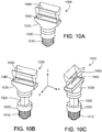
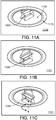
- the “adjustable mount” may correspondingly be understood as a translational mount, a rotatable mount and/or a tiltable mount.
- the rotation of the secondary optic or luminaire module may be 0-10°, preferable 0-20°, more preferably 0-30°, even more preferably 0-40°, most preferably 0-90°.
- the translation of the secondary optic or luminaire module may be 0-50cm, preferably 0-30cm, more preferably 1-30cm, even more preferably 1-20cm.
- the angular tilt of the secondary optic or luminaire module may be 0- 10°, preferable 0-20°, more preferably 0-30°, even more preferably 0-45°.
- FIG. 1A schematically shows three adjustable illumination devices 100-1, 100-2, and 100-3 mounted to a ceiling 180 of a room and configured to illuminate the room. Light output from the adjustable illumination devices 100-1, 100-2, and 100-3 occurs at different distances from ceiling 180.
- a Cartesian coordinate system is shown for reference. The x-y plane is parallel to the ceiling 180 and a floor 190 (e.g., a floor or a desk,) while the z-axis is perpendicular to both.
- each adjustable illumination device includes one or more light emitting elements (LEEs, such as, e.g., light emitting diodes (LEDs)) configured to emit light and a redirecting optic.
- LOEs light emitting elements
- the redirection optic is also referred to as secondary optic.
- the adjustable illumination device is configured to redirect the emitted light as output light in one or more direct angular ranges 262 and one or more indirect angular ranges 162, 162', for example, on one or more sides or in one or more corners of a ceiling of a room.
- the adjustable illumination devices 100-1, 100-2, 100-3 are configured to provide direct illumination of the area (in accordance with the one or more direct angular ranges 262), and indirect illumination towards the ceiling 180 (as illustrated by the indirect angular distributions 162, 162').
- the target area in FIG. 1A is the floor 190, more generally, the target area can be a workspace, a desk, a floor, or other target area.
- Rays 152 and 152' encompass the direct angular range 262.
- the prevalent direction of the angular ranges are indicated by arrows.
- a secondary optic 140 of each adjustable illumination device is positioned at a different distance from the ceiling 180: secondary optic 140 of the adjustable illumination device 100-1 is located at a distance HI from the ceiling 180; secondary optic 140 of the adjustable illumination device 100-2 is located at a distance H2 from the ceiling 180 (H2 > HI); and secondary optic 140 of the adjustable illumination device 100-3 is located at a distance H3 from the ceiling 180 (H3 > H2.)
- the distance of the secondary optics to the ceiling can be 5cm or more, 10cm or more, 15cm or more, or 20cm or more.
- the distance of the secondary optics from the ceiling 180 can affect the forward and/or backward illumination distribution of the adjustable illumination device.
- the size of the illuminated area of the floor 190 and the ceiling 180 depends on the relative position of the secondary optic 140 with respect to the ceiling 180.
- the adjustable illumination device 100-1 with a fully retracted luminaire module provides the largest area of direct illumination and the smallest area of indirect illumination
- the adjustable illumination device 100-3 with a fully extended luminaire module provides the smallest area of direct illumination and the largest area of indirect illumination.
- the secondary optic is fixed with respect to the LEEs, therefore, the secondary optic and LEEs together move relative to the ceiling.
- adjustable illumination devices 100-1, 100-2, and 100-3 can be configured to provide a particular light intensity distribution on a target area, subject to given constraints.
- the adjustable illumination devices 100-1, 100-2, and 100-3 can be configured to substantially uniformly illuminate the floor 190 (e.g., to obtain approximately 10% overlap between each of the adjacent direct angular ranges at the floor level, thereby providing continuous illumination of the floor with little variation in intensity) or focus the direct illumination on respective target areas.
- the adjustable illumination devices can be configured to be in conformance with glare standards (e.g., light redirected towards the floor 190 in any of the direct angular range 262 does not exceed a glancing angle of 40° with respect to the z-axis.)
- the adjustable illumination devices 100-1, 100-2, and 100-3 can be configured to maintain glare standards desired of traditional illumination systems (not illustrated).
- Such configurations of the adjustable illumination devices can be implemented by selecting appropriate combinations of system parameters including (i) direct angular range 262 of direct light output by the adjustable illumination devices 100-1, 100-2, and 100-3; (ii) indirect angular ranges 162, 162' of indirect light output by the adjustable illumination devices 100-1, 100-2, and 100-3; (iii) distance between nearest adjustable illumination devices 100-1, 100-2, and 100-3, e.g., about 6ft or more, about 10ft or more, about 15ft or more, about 24ft; and (iv) distance H from the ceiling 180 to an effective center of the adjustable illumination devices 100- 1, 100-2, and 100-3.
- the positive z-direction is referred to herein as the "forward” direction and the negative z-direction is the “backward” direction.
- Sections through the illumination devices parallel to the x-z plane are referred to as the "cross-section” or “cross-sectional plane” of the illumination device.
- FIG. IB shows, for the x-z plane, an example light intensity profile 151 of an adjustable illumination device, such as adjustable illumination devices 100-1, 100-2, and 100-3.
- the intensity profile 151 includes four lobes 152a, 152b, 162a, and 162b.
- lobes 152a and 152b may be notional as both may be superimposed, for example, and appear indistinguishable from each other. The result may be similar to what is described with respect to FIG. 1C .
- the adjustable illumination device is configured to direct substantially all of the indirect (background) light 162a, 162b into a range of polar angles between -90° and -110°, and between +90° and +110° in a cross-sectional plane (x- z) of the adjustable illumination device.
- the adjustable illumination device is also configured to direct substantially all of the forward (e.g., direct) light into a pair of narrow lobes 152a, 152b having a range of polar angles having maximum intensity at -50° and +50° in the x-z cross- sectional plane, respectively.
- Lobes 152a, 152b of the light intensity profile 151 correspond to direct angular ranges and lobes 162a, 162b correspond to indirect angular ranges.
- FIG. 1C shows another example light intensity profile 153 from an adjustable illumination device 100.
- intensity profile 153 includes lobes 162a and 162b having maximal intensity at -100° and +100°, respectively. These lobes correspond to indirect illumination.
- Intensity profile 153 also includes a single lobe 154 in the forward direction, providing illumination in an angular range from about -60 ⁇ 0>to +60 °.
- light emitting in the forward direction may be within a range between about -50° and about +50° (e.g., from about -60° and about +60°, from about -70° and about +70°) in order to reduce glare from the adjustable illumination device.
- composition and geometry of components of the adjustable illumination device affect the light intensity profile and may be selected to provide direct and indirect illumination into ranges having varying angular width and direction.
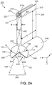
- FIG. 2A shows an example of a luminaire module 200.
- the luminaire module 200 includes a mount 210 having a plurality of LEEs 212 distributed along a first surface 210a of the mount 210.
- the luminaire module 200 includes primary optics 220 (e.g., optical couplers corresponding to the LEEs 212), a light guide 230, and secondary optics 240 (e.g., an optical extractor.)
- Light emitted by the LEEs 212 couples into the light guide 230 (either directly or upon reflection by surfaces 221 and 222 of primary optics 220) and is guided by the light guide 230 to secondary optics 240.
- luminaire module 200 corresponds to light output in the angular range 262
- the indirect illumination corresponds to light output in angular ranges 142, 142'.
- luminaire modules can be configured to output light in forward direction in an angular range qualitatively similar to angular range 154 of FIG. 1C , for example.
- luminaire module 200 extends along the y-direction, so this direction is referred to as the "longitudinal" direction of the luminaire module.
- implementations of luminaire modules can have a plane of symmetry parallel to the y-z plane. This is referred to as the "symmetry plane" of the luminaire module.
- Mount 210, the light guide 230, and the secondary optic 240 extend a length L along the y-direction, so that the luminaire module is an elongated luminaire module with an elongation of L that may be about parallel to a wall of a room (e.g., a ceiling of the room).
- L can vary as desired.
- L is in a range from about 1 cm to about 200 cm (e.g., 20 cm or more, 30 cm or more, 40 cm or more, 50 cm or more, 60 cm or more, 70 cm or more, 80 cm or more, 100 cm or more, 125 cm or more, or, 150 cm or more).
- the number of LEEs 212 on the mount 210 will generally depend, inter alia, on the length L, for example, more LEEs may be used for longer luminaire modules.
- a luminaire module may include as few as about 10 LEEs or as many as about 1,000 LEEs or more (e.g., about 50 LEEs, about 100 LEEs, about 200 LEEs, about 500 LEEs).
- the density of LEEs (e.g., number of LEEs per unit length) will also depend on the nominal power of the LEEs and luminance desired from the luminaire module. For example, a relatively high density of LEEs can be used in applications where high luminance is desired or where low power LEEs are used.
- the luminaire module 200 has an LEE density along its length of 0.1 LEE per centimeter or more (e.g., 0.2 per centimeter or more, 0.5 per centimeter or more, 1 per centimeter or more, 2 per centimeter or more).
- LEEs can be evenly spaced along the length, L, of the luminaire module.
- a heat-sink 205 can be attached to the mount 210 to extract heat emitted by the plurality of LEEs 212.
- the heat-sink 205 can be disposed on a surface of the mount 210 opposing the side of the mount 210 on which the LEEs 212 are disposed.
- the primary optics 220 include one or more solid pieces of transparent optical material (e.g., a glass material or a transparent organic plastic, such as polycarbonate or acrylic) having surfaces 221 and 222 positioned to reflect light from the LEEs 212 towards the light guide 230.
- surfaces 221 and 222 are shaped to collect and at least partially collimate light emitted from the LEEs.
- surfaces 221 and 222 can be straight or curved. Examples of curved surfaces include surfaces having a constant radius of curvature, parabolic or hyperbolic shapes.
- surfaces 221 and 222 are coated with a highly reflective material (e.g., with reflectivities exceeding 80% or 90% of the visible light spectrum such as a reflective metal, e.g. aluminum or silver), to provide a highly reflective optical interface.
- a highly reflective material e.g., with reflectivities exceeding 80% or 90% of the visible light spectrum
- a reflective metal e.g. aluminum or silver
- the cross-sectional profile of primary optics 220 can be uniform along the length L of luminaire module 200. Alternatively, the cross-sectional profile can vary. For example, surfaces 221 and/or 222 can be curved out of the x-z plane.
- the surface of the primary optics 220 adjacent to an upper edge 231 of the light guide 230 is optically coupled to the edge 231.
- the surfaces of the interface are attached using a material that substantially matches the refractive index of the material forming the primary optics 220 or light guide 230 or both.
- the primary optics 220 can be affixed to the light guide 230 using an index matching fluid, grease, or adhesive.
- the primary optics 220 are fused to the light guide 230 or they are integrally formed from a single piece of material (e.g., coupler and light guide may be monolithic and may be made of a solid transparent optical material).
- primary optics 220 are designed to restrict the angular range of light entering the light guide 230 (e.g., to within +/-40 degrees) so that at least a substantial amount of the light is coupled into spatial modes in the light guide 230 that undergoes TIR at the side surfaces of the light guide.
- the example light guide 230 has a uniform thickness T, which is the distance separating two planar opposing surfaces of the light guide.
- T is sufficiently large so the light guide has an aperture at an upper edge 231 sufficiently large to approximately match (or exceed) the aperture of primary optics 220.
- T is in a range from about 0.05 cm to about 2 cm (e.g., about 0.1 cm or more, about 0.2 cm or more, about 0.5 cm or more, about 0.8 cm or more, about 1 cm or more, about 1.5 cm or more).
- a narrow light guide also provides a narrow exit aperture. As such light emitted from the light guide can be considered to resemble the light emitted from a one-dimensional linear light source, also referred to as an elongate virtual filament.
- the light guide 230 can be formed from a piece of transparent material (e.g., glass material such as BK7, fused silica or quartz glass, or a transparent organic plastic, such as polycarbonate or acrylic) that can be the same or different from the material forming the primary optics 220.
- the example light guide 230 extends length L in the y-direction, has a uniform thickness T in the x-direction, and a uniform depth D in the z-direction.
- the dimensions D and T are generally selected based on the desired optical properties of the light guide and/or the direct/indirect intensity distribution.
- light coupled into the light guide 230 from the primary optics 220 (depicted by angular range 252) reflects off the planar surfaces of the light guide by total internal reflection and spatially mixes within the light guide.
- the mixing can help achieve illuminance and/or color uniformity at the output end 232 of the light guide 230 at the secondary optic 240.
- the depth, D, of the light guide 230 can be selected to achieve adequate uniformity at the exit aperture (i.e., at output end 232) of the light guide.
- D is in a range from about 1 cm to about 20 cm (e.g., 2 cm or more, 4 cm or more, 6 cm or more, 8 cm or more, 10 cm or more, 12 cm or more).
- the primary optics 220 and the light guide 230 are formed from solid pieces of transparent optical material, hollow structures are also possible.
- the primary optics 220 or the light guide 230 or both may be hollow with reflective inner surfaces rather than being solid. As such material cost can be reduced and absorption in the light guide avoided.
- specular reflective materials may be suitable for this purpose including materials such as 3M VikuitiTM or Miro IVTM sheet from Alanod Corporation where greater than 90% of the incident light would be efficiently guided to the secondary optic.
- secondary optics 240 adjacent to the output end 232 of light guide 230 is optically coupled to the output end 232.
- secondary optics 240 can be affixed to light guide 230 using an index matching fluid, grease, or adhesive.
- secondary optics 240 are fused to light guide 230 or they are integrally formed from a single piece of material.
- the secondary optics 240 is also composed of a solid piece of transparent optical material (e.g., a glass material or a transparent organic plastic, such as polycarbonate or acrylic) that can be the same as or different from the material forming the light guide 230.
- the piece of dielectric material includes redirecting (e.g., flat) surfaces 242 and 244 and curved surfaces 246 and 248.
- the flat surfaces 242 and 244 represent first and second portions of a redirecting surface 243, while the curved surfaces 246 and 248 represent first and second output surfaces of the luminaire module 200.
- surfaces 242 and 244 are coated with a highly reflective material (e.g., with reflectivities exceeding 80% or 90% of the visible light spectrum, e.g. a highly reflective metal, such as aluminum or silver) over which a protective coating may be disposed.
- a highly reflective material e.g., with reflectivities exceeding 80% or 90% of the visible light spectrum, e.g. a highly reflective metal, such as aluminum or silver
- surfaces 242 and 244 provide a highly reflective optical interface for light entering an input end of the secondary optics from light guide 230.
- the surfaces 242 and 244 include portions that are transparent to the light entering at the input end of the secondary optics. For example, these portions can be uncoated regions or discontinuities (e.g., slots, slits, apertures) of the surfaces 242 and 244.
- the transmitted light exits the secondary optics 240 through surfaces 242 and 244 in angular range 262. The transmitted light also may also be refracted.
- an included angle e.g., the smallest included angle between the surfaces 244 and 242
- the included angle can be relatively small (e.g., from 30° to 60°).
- the included angle is in a range from 60° to 120° (e.g., about 90°).
- the included angle can also be relatively large (e.g., in a range from 120° to 150° or more).
- the output surfaces 246 and 248 of the secondary optic 240 are curved with a constant radius of curvature that is the same for both.
- luminaire module 200 has a plane of symmetry intersecting apex 241 parallel to the y-z plane. Because surfaces 246 and 248 are curved, they may serve to focus light (e.g., reduce the amount of divergence of the light) reflected by redirecting surfaces 242 and 244.
- the geometry of the secondary optics 240 plays a role in shaping the lobes of light emitted by the adjustable illumination device.
- the vertex angle can be used to provide the desired direction of the lobes of indirect light emitted by the adjustable illumination device.
- the emission spectrum of the luminaire module 200 corresponds to the emission spectrum of the LEEs 212.
- a wavelength-conversion material may be positioned in the luminaire module, for example remote from the LEEs, so that the wavelength spectrum of the luminaire module is dependent both on the emission spectrum of the LEEs and the composition of the wavelength-conversion material.
- a wavelength-conversion material can be placed in a variety of different locations in the luminaire module 200.
- a wavelength- conversion material may be disposed proximate the LEEs 212, adjacent surfaces 242 and 244 of the secondary optic 240, on the exit surfaces 246 and 248 of the secondary optic 240, placed at a distance from the exit surfaces 246 and 248, and/or at other locations.
- a layer of wavelength-conversion material may be attached to light guide 230 held in place via a suitable support structure (not illustrated), disposed within the secondary optics (also not illustrated) or otherwise arranged, for example.
- Wavelength-conversion material that is disposed within the secondary optics may be configured as a shell or other object and disposed within a notional area that is circumscribed by R/n or even smaller
- the light converting material diffuses light as it converts the wavelengths, provides mixing of the light and can help uniformly illuminate tertiary reflectors (not shown in FIG. 2A ).
- the geometry of secondary optics 240 plays an important role in shaping the light emitted by the adjustable illumination device.
- the shape of surfaces 242 and 244 may vary in accordance with the desired emission. While surfaces 242 and 244 are depicted as planar surfaces, other shapes are also possible. For example, these surfaces can be curved or faceted. Curved redirecting surfaces 242 and 244 can be used to narrow or widen the beam. Depending of the divergence of the angular range of the light that is received at the input end of the secondary optics, concave reflective surfaces 242, 244 can narrow the light intensity distribution output by the secondary optics 240, while convex reflective surfaces 242, 244 can widen the light intensity distribution output by the secondary optics 240. As such, suitably configured redirecting surfaces 242, 244 may introduce convergence or divergence into the light. Such surfaces can have a constant radius of curvature, can be parabolic, hyperbolic, or have some other curvature.
- FIGS. 2B and 2D show redirecting surfaces 243-b and 243-d having an apex 241 that separates the curved redirecting surface 242, 244.
- the apex 241 of the redirecting surface can be a rounded vertex with a non-zero radius of curvature.
- the redirecting surface 242, 244 have arcuate shapes in the cross-sectional plane substantially perpendicular to the longitudinal dimension of the luminaire module 200.
- the first and second portions of the redirecting surface 242, 244 can be parabolic, hyperbolic, and/or can have constant curvatures different from each other.
- curvatures of the first and second portions of the redirecting surface 242, 244 can be both negative (e.g., convex with respect to a direction of propagation of light from the input end of the secondary optics to the redirecting surface), can be both positive (e.g., concave with respect to the propagation direction), or one can be positive (convex) and the other one can be negative (concave).
- FIG. 2E shows a redirecting surface 243 -e shaped as an arc of a circle, ellipse, parabola or other curve.
- the first and second portions of the redirecting surface 242, 244 represent first and second portions of the arc of the circle.
- the curvature of the redirecting surface 243 is negative (e.g., convex with respect to a direction of propagation of light from the input end of the secondary optics to the redirecting surface 243).
- FIG. 2C shows a redirecting surface 243-c that includes faceted surfaces 242, 244.
- the surfaces meet at apex 241.
- the facets forming surface 242 meet at an apex 2444 while the facets forming surface 242 meet at an apex 2411.
- the facets of each surface can have linear or arcuate shapes.
- the facets may be arranged to reflect the light received from the input end of the secondary optics in different angular sub-ranges. In this manner, light provided by the different facets of each of the surfaces 242 and 244 is output at the output surfaces 246 and 248, respectively, as two intensity lobes that can be manipulated differently, e.g., to illuminate different targets.
- FIG. 2F shows a redirecting surface 243 -f where the redirecting surfaces 242 and 244 are separated by a slot 245, in general a suitably formed aperture.
- Slot 245 corresponds to a gap in the reflective material at the surface and allows for light to be transmitted in a forward direction out of the secondary optics.
- the width of the slot 245 may vary as desired, in accordance with the desired proportion of light to be transmitted by the secondary optics.
- FIG. 2G shows a redirecting surface 243-g in which surface 242 includes a slot 2455' and surface 244 includes a slot 2455".
- Such slots may represent an opening in a coating providing a reflecting layer of the redirecting surface 243-g and allows transmission of at least some (e.g., about 1%, 5%, 10%, 20% or more) of the light received from the light guide.
- each slot may extend along the entire longitudinal extension of the luminaire module 200.
- redirecting surfaces may include multiple slots each extending a fraction of the length of the module.
- embodiments showing a single slot and two slots (in a cross-section) are illustrated, it will be appreciated that any number of slots may be included depending on the desired transmission properties of the secondary optics.
- embodiments may feature additional optical elements located at the slots to shape the transmitted light.
- secondary optics may include focusing or defocusing elements, diffusing elements, and/or diffractive elements that provide additional light shaping to the light transmitted by the slots.
- the curves corresponding to each of the cross-sectional planes illustrated in FIGS. 2B-2G can have different shapes and different discontinuities in other cross-sectional planes along the longitudinal dimension of the luminaire module 200.
- different cross-sections of a redirecting surface 243 can have different combinations of disjoint or joined piecewise differentiable curves.
- the luminaire module 200 can be used in an adjustable illumination device, where direct illumination corresponds to light output through the transparent portions of the redirecting surface 243-f or 243-g, and indirect illumination corresponds to light output through surfaces 246/248 of the luminaire module 200, as described below in connection with FIGS. 3-4 , for example.
- redirecting surfaces that do not include slots in the reflective layer to provide both direct and indirect light as shown in FIGS. 3-4 .
- a partially-reflecting layer may instead be used (e.g., a partially-silvered surface).
- the redirecting surface e.g., as illustrated in FIGS. 2B-2E ) acts as a beam splitter rather than a mirror, and transmits a desired portion of incident light, while reflecting the remaining light.
- additional optical layers may be included adjacent the partially-reflecting layer that can further shape the transmitted light.
- a diffusing layer may be included.
- a lens or lens array may be included (e.g., such as a micro- structured film composed of lenticular lenses or prisms).
- luminaire module 200 can be used as a component of the adjustable illumination device 100, where the output light is further redirected by tertiary reflectors (not shown) to provide direct illumination.
- the shape of the output surfaces 246 and 248 of the secondary optic 240 can vary as well, and thus, the surfaces 246 and 248 can steer and shape the beam of light.
- the radius of curvature of these surfaces can be selected so that the surfaces introduce a desired amount of convergence into the light.
- Aspheric surfaces can also be used.
- contours of the redirecting surface of the secondary optic 240 in cross-sectional planes substantially perpendicular to the longitudinal dimension of the luminaire module 200 apply to contours of the output surfaces 246, 248 of the secondary optics 240 in such cross-sectional planes.
- choices of redirecting surfaces described in FIGS. 2B-2G can provide an additional degree of freedom for modifying the (direct or indirect or both) intensity distribution (e.g., illumination pattern) of the light output by the adjustable illumination devices.
- the luminaire modules 200, direct secondary reflectors, indirect optics, the arrangement of indirect and direct LEEs with respect to a mount of an adjustable illumination device, and the first and second apexes may be iteratively modified in their spatial position and/or optical properties (spatial shape of reflective surfaces, index of refraction of solid material, spectrum of emitted or guided light, etc.) to provide a predetermined direct and/or indirect illumination distribution.
- the geometry of the elements can be established using a variety of methods.
- the geometry can be established empirically.
- the geometry can be established using optical simulation software, such as LighttoolsTM, TraceproTM, FREDTM or ZemaxTM, for example.
- luminaire modules can include other features useful for tailoring the intensity profile.
- luminaire modules can include an optically diffusing material and/or structure that scatters light, which can be configured to homogenize the luminaire module's intensity profile to predetermined degrees.
- surfaces 242 and 244 can have an engineered roughness or interface structure or include a diffusely reflecting material, rather than a specular reflective material, and/or a coat can be applied to these surfaces.
- the optical interfaces at surfaces 242 and 244 can diffusely reflect light, and/or scatter light into broader lobes that would be provided by similar structures utilizing specular reflection at these interfaces.
- these surfaces can include structure that facilitates various intensity distributions.
- surfaces 242 and 244 can each have multiple planar facets at differing orientations.
- surfaces 242 and 244 can have structure thereon (e.g., structural features that scatter or diffract light).
- a light scattering material can be disposed on surfaces 246 and 248 of secondary optics 240 (e.g., surfaces 246 and 248 can have an engineered roughness or include a layer of a diffusely transmitting material).
- surfaces 246 and 248 need not be surfaces having a constant radius of curvature.
- surfaces 246 and 248 can include portions having differing curvature and/or can have structure thereon (e.g., structural features that scatter or diffract light).
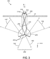
- FIG. 3 schematically shows an adjustable illumination device 300 mounted to a ceiling 180.
- the adjustable illumination device 300 includes a solid embodiment of the luminaire module 200 described above in connection with FIG. 2A and the position of the luminaire module 200 can be adjusted relative to the ceiling 180.
- the adjustable illumination device 300 is elongated along the y-axis (perpendicular to the page.)
- the adjustable illumination device 300 includes a mount 210, multiple LEEs 212, primary optics 220, a light guide 230 and a solid secondary optic 240.
- the mount 210 has a first surface 210a with a normal parallel to the z- axis.
- the multiple LEEs 212 are disposed on the first surface 210a of the mount, such that the LEEs 212 emit, during operation, light in a first angular range with respect to the normal to the first surface 210a of the mount 210.
- the primary optics 220 are arranged on the first surface 210a and coupled with the LEEs 212.
- the primary optics 220 are shaped to redirect light received from the LEEs 212 in a first angular range, and to provide the redirected light in a second angular range 252.
- a divergence of the second angular range 252 is smaller than a divergence of the first angular range at least in the x-z plane.
- the light guide 230 includes input and output ends. In this case, the input and output ends of the light guide 230 have substantially the same shape.
- the input end of the light guide 230 is coupled to the primary optics 220 to receive the light provided by the primary optics 220 in the second angular range 252. Further, in this example, the light guide 230 is shaped to guide the light received from the primary optics 220 in the second angular range 252 and to provide the guided light at the output end of the light guide 230.
- the secondary optic 240 includes an input end, a redirecting surface 243-g opposing the input end and first and second output surfaces.
- the input end of the solid secondary optic 240 is coupled to the output end of the light guide 230 to receive the light provided by the light guide 230.
- the redirecting surface 243-g has been described above in connection with FIG. 2G .
- the redirecting surface 243-g has first and second portions that reflect the light received at the input end of the secondary optic 240 and provide the reflected light in third and fourth angular ranges with respect to the normal to the first surface 210a of the mount 210 towards the first and second output surfaces, respectively. At least prevalent directions of propagation of light in the third and fourth angular ranges are different from each other and from a prevalent direction of propagation of light in the second angular range 252 at least perpendicular to the y- axis.
- some regions of the first and second portions of the redirecting surface 243- g are transparent (e.g., are uncoated with a reflecting layer, or have slots, apertures, etc.), such that the first and second portions of the redirecting surface 243 -g transmit (and sometime refract) the light received at the input end of the solid secondary optic 240 and output the transmitted ("leaked") and refracted light in fifth angular range 262 with respect to the normal to the first surface 210a of the mount 210, outside the first and second portions of the redirecting surface 243-g.
- the angular range 262 may correspond to the second angular range 252 of the light output at the output end of the light guide 230.
- the first output surface is shaped to refract the light provided by the first portion of the redirecting surface 243-g in the third angular range as first refracted light, and to output the first refracted light in a seventh angular range 142 with respect to the normal to the first surface 210a of the mount 210 outside the first output surface of the solid secondary optic 240.
- the second output surface is shaped to refract the light provided by the second portion of the redirecting surface 243-g in the fourth angular range as second refracted light, and to output the second refracted light in an eighth angular range 142' with respect to the normal of the first surface 210a of the mount 210 outside the second output surface of the solid secondary optic 240.
- prevalent directions of propagation of light in the seventh 142 and eighth 142' angular ranges are different from each other and have a non-zero component antiparallel with the normal to the first surface 210a of the mount 210.
- the adjustable illumination device 300 can provide direct illumination (in angular range 262) on a target space located in the positive direction of the z-axis (e.g., on the floor 190 or a desk) and indirect illumination (in angular ranges 142, 142') towards the ceiling 180.
- FIG. 4 shows another example of an adjustable illumination device 400.
- the adjustable illumination device 400 includes a hollow embodiment (i.e., embodiments that do not include a light guide and/or solid secondary optics) of a luminaire module described above in connection with FIG. 2A .
- a position of the luminaire module can be adjusted relative to the ceiling 180.
- the adjustable illumination device 400 includes a housing (not shown in FIG. 4 ) to which the luminaire module can be coupled.
- the housing can be a recess ceiling mount and the position of the luminaire module can be adjusted relative to the housing.
- the adjustable illumination device 400 is elongated along the y-axis (perpendicular to the page.)
- the adjustable illumination device 400 includes a mount 210, multiple LEEs 212, primary optics 220, and a secondary optic 440.
- the mount 210 has a first surface 210a with a normal parallel to the z- axis.
- the multiple LEEs 212 are disposed on the first surface 210a of the mount, such that the LEEs 212 emit, during operation, light in a first angular range with respect to the normal to the first surface 210a of the mount 210.
- the primary optics 220 are arranged on the first surface 210a and coupled with the LEEs 212.
- the primary optics 220 are shaped to redirect light received from the LEEs 212 in the first angular range, and to provide the redirected light in a second angular range 252.
- a divergence of the second angular range 252 is smaller than a divergence of the first angular range at least in the x-z plane.
- the secondary optic 440 includes a redirecting surface 243-b/g.
- the redirecting surface 243-b/g has first and second portions that are shaped as described above in connection with FIG. 2B .
- some regions of the first and second portions of the redirecting surface 243-b/g are transparent (e.g., are uncoated with a reflecting layer, or have slots, apertures, etc.)
- the first and second portions of the redirecting surface 243-b/g reflect the light received from the primary optics 220 in the second angular range 252, and provide the reflected light in third 142 and fourth 142' angular ranges with respect to the normal to the first surface 210a of the mount 210, respectively.
- At least prevalent directions of propagation of light in the third 142 and fourth 142' angular ranges are different from each other and from a prevalent direction of propagation of light in the second angular range 252 at least perpendicular to the y-axis. Moreover, prevalent directions of propagation of light in the third 142 and fourth 142' angular ranges are different from each other and have a non-zero component antiparallel with the normal to the first surface 210a of the mount 210.
- the transparent regions of the first and second portions of the redirecting surface 243-b/g transmit the light received from the primary optics 220 in the second angular range 252, and output the transmitted ("leaked") light in fifth angular range 262 with respect to the normal to the first surface 210a of the mount 210.
- the fifth angular range 262 may correspond to the second angular range 252 of the light received from the primary optics 220.
- transmission ("leakage") of light in fifth angular range 262 occurs without refraction (e.g., through apertures of the redirected surface 243-b/g)
- the fifth angular range 262 corresponds to the second angular range 252 of the light received at the secondary optic 440.
- the adjustable illumination device 400 provides direct illumination (in angular range 262) on a target space located in the positive direction of the z-axis (e.g., on the floor 190 or a desk) and indirect illumination (in angular ranges 142, 142') towards the ceiling 180.
- secondary optic 440 includes partially light-transmissive (e.g., about 1%, 5%, 10%, 20% or more light transmission), redirecting surfaces, such as 243f/g shown in FIGs.
- the adjustable illumination device 400 provides direct illumination on the target space located in the positive direction of the z-axis (e.g., on the floor 190) in angular range 262 and indirect illumination towards the ceiling 180 in angular ranges 142, 142'.
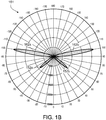
- luminaire modules can be configured to direct substantially all of the light into a range of angles between 90° to 120° and -90° to -120° in a cross-sectional plane of the luminaire module, where 0° corresponds to the direction of direct illumination and 180° corresponds to the direction of indirect illumination.
- the direction of direct illumination corresponds to a normal to the mount 210 and parallel to the light guide 230, and can be toward the target space (e.g., the floor 190) for an illumination device mounted on a ceiling.
- target space e.g., the floor 190
- the intensity profile in the cross-sectional plane is given by traces 510 and 510', which correspond to the angular ranges 142 and 142' respectively.
- the intensity profile in the cross- sectional plane has maximum luminance at about 95° to 110°, and -95° to -110° respectively.
- Luminaire modules can be configured to direct little or no illumination into certain angular ranges, for example, to avoid glare. In this example, the luminaire module outputs almost no direct illumination toward the target space in ranges from 120° to 180° and -120° to -180°.
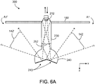
- FIG. 6A is an example of an adjustable illumination device 300 with a fully extended luminaire module (i.e., the secondary optic 240 is at maximum distance to the ceiling 180.)
- Light emitted by the LEEs 212 is guided through the light guide 230 to the secondary optic 240 and redirected by the redirecting surface 243 towards the output surfaces of the secondary optic 240.
- the redirected light is output through the output surfaces of the secondary optic 240 in angular ranges 142, 142' towards the ceiling 180 (e.g., ceiling).
- the adjustable illumination device 300 illuminates areas Al, A of the ceiling 180.
- Areas Al, A are the largest areas the adjustable illumination device 300 can illuminate since the secondary optic 240 is positioned at a maximum distance to the ceiling 180.
- Results of an optical simulation of the example illumination device 300 with LighttoolsTM are shown in FIG. 6A .
- the length L (see Fig. 2A ) of the light guide is about 600 mm and the depth D (see Fig. 2A ) of the light guide is about 100 mm.
- the simulation is for a full extension of the example illumination device 300 to about 100 mm below the ceiling.
- the angular ranges 142, 142' have prevalent directions oriented along +100 degrees, -100 degrees respectively, and divergencies of about 20 degrees, as shown, for example, in FIG. 5 .
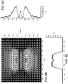
- FIG. 6B is a contour plot of a simulated intensity distribution on the ceiling 180 that corresponds to the configuration of the adjustable illumination device 300 shown in FIG. 6A (i.e., full extension of the luminaire module) and the intensity profile shown in FIG. 5 .
- the y-axis of the plot shown in FIG. 6B refers to the illumination distribution in the longitudinal direction of the adjustable illumination device 300 (y-axis in FIG. 2A ) and the x-axis of the plot refers to the illumination distribution in the transverse direction of the adjustable illumination device 300 (x-axis in FIG. 2A .)
- the second axis of the plot shown in FIG. 6C refers to illuminance (lux) in the transverse direction of the adjustable illumination device 300.
- lux illuminance
- the illuminance between a distance of-1,000 and +1, 000mm from the adjustable illumination device in transverse direction reaches up to 3,500 lux.
- the second axis of the plot shown in FIG. 6D refers to illuminance (lux) in the longitudinal direction of the adjustable illumination device 300.
- lux illuminance
- the illuminance between a distance of -400 and +400mm from the adjustable illumination device along the longitudinal direction reaches up to 2,250 lux.
- FIG. 7A is an example of the adjustable illumination device 300 with a partially extended luminaire module.
- the secondary optic 240 is at a distance of about 75 mm to the ceiling 180.
- the adjustable illumination device 300 illuminates areas A2, A2' of the ceiling 180 that are smaller than the areas Al, A.
- the intermediate distance between the secondary optic and the ceiling represents approximately 75% of the depth of the luminaire module.
- FIG. 7B is a contour plot of a simulated intensity distribution on the ceiling 180 that corresponds to the configuration of the adjustable illumination device 300 shown in FIG. 7A (i.e., partial extension of the luminaire module) and the intensity profile shown in FIG. 5 .
- the y- axis of the plot shown in FIG. 7B refers to the illumination distribution in the longitudinal direction of the adjustable illumination device 300 (y-axis in FIG. 2A ) and the x-axis of the plot refers to the illumination distribution in the transverse direction of the adjustable illumination device 300 (x-axis in FIG. 2A ).
- FIG. 7C is a cross section plot of a simulated intensity distribution in the transverse direction (x-axis) of the adjustable illumination device 300.
- the second axis of the plot shown in FIG. 7C refers to illuminance (lux) in the transverse direction of the adjustable illumination device 300.
- illuminance lux
- the illuminance between a distance of -900 and +900mm from the adjustable illumination device in transverse direction reaches up to 4,750 lux.
- FIG. 7D is a cross section plot of a simulated intensity distribution in the longitudinal direction (y-axis) of the adjustable illumination device 300.
- the second axis of the plot shown in FIG. 7D refers to illuminance (lux) in the longitudinal direction of the adjustable illumination device 300.
- lux illuminance
- the illuminance between a distance of -375 and +375mm from the adjustable illumination device along the longitudinal direction reaches up to 2,400 lux.
- FIG. 8A is an example of the adjustable illumination device 300 with a further retracted luminaire module.
- the secondary optic 240 is at about 50 mm distance to the ceiling 180.
- the adjustable illumination device 300 illuminates areas A3, A3' of the ceiling 180 are smaller than the areas A2, A2'. Areas A3, A3' are smaller areas since the secondary optic 240 is positioned at about 50% distance to the ceiling 180.
- FIG. 8B is a contour plot of a simulated intensity distribution on the ceiling 180 that corresponds to the configuration of the adjustable illumination device 300 shown in FIG. 8A (i.e., full retraction of the luminaire module) and the intensity profile shown in FIG. 5 .
- the y-axis of the plot shown in FIG. 8B refers to the illumination distribution in the longitudinal direction of the adjustable illumination device 300 (y-axis in FIG. 2A ) and the x-axis of the plot refers to the illumination distribution in the transverse direction of the adjustable illumination device 300 (x-axis in FIG. 2A .)
- FIG. 8C is a cross section plot of a simulated intensity distribution in the transverse direction (x-axis) of the adjustable illumination device 300.
- the second axis of the plot shown in FIG. 8C refers to illuminance (lux) in the transverse direction of the adjustable illumination device 300.
- lux illuminance
- the illuminance between a distance of -600 and +600mm from the adjustable illumination device in transverse direction reaches up to 7,500 lux.
- FIG. 8D is a cross section plot of a simulated intensity distribution in the longitudinal direction (y-axis) of the adjustable illumination device 300.
- the second axis of the plot shown in FIG. 8D refers to illuminance (lux) in the longitudinal direction of the adjustable illumination device 300.
- lux illuminance
- the illuminance between a distance of -350 and +350mm from the adjustable illumination device along the longitudinal direction reaches up to 2,500 lux.
- FIGS 6D , 7D , and 8D show that the illumination of the ceiling 180 remains substantially above 2000 lux along the elongate dimension of the adjustable illumination device 300 (i.e., the length of the adjustable illumination device 300 defined by the Y coordinate) even though the extension of the luminaire module (i.e., the distance of the secondary optic 240 to the ceiling 180) varies.
- the illumination of the ceiling 180 along the X coordinate varies dependent on the extension of the luminaire module.
- the adjustable illumination device 300 with a fully extended luminaire module illuminates the ceiling 180 at above 500 lux to about 600mm in the X direction from the adjustable illumination device 300.
- the adjustable illumination device 300 with a fully retracted luminaire module illuminates the ceiling 180 at above 500 lux to about 400mm in the X direction from the adjustable illumination device 300.
- the mounting structure that allows for adjustment of the position of the luminaire module relative to the ceiling (or other background area) can be configured in different ways.
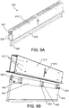
- an adjustable illumination device 900 includes a housing 910 that allows for mounting the adjustable illumination device to a ceiling.
- the adjustable illumination device 900 includes a luminaire module 930 (e.g., having a structure similar to luminaire module 200), the housing 910, and a sliding mechanism 920 for adjusting an extension of the luminaire module 930 relative to the housing 910.
- the luminaire module 930 can be moved relative to the housing 910 (e.g., the luminaire module can be slid back and forth in the housing to extend or retract the luminaire module.) In some implementations, one or more tools 940 can be used to push/pull the luminaire module 930 into and out of the housing 910.
- the one or more tools 940 can be permanently or removably coupled with the luminaire module at one or more locations.
- such tools can be arranged at opposite ends with respect to the length of the light guide and/or in the center of the light guide proximate the secondary optics.
- the tool can comprise a tab handle, hook, a spring, or alike.
- One end of the housing 910 includes a flange that sits flush with the ceiling when the adjustable illumination device is installed in a room. This end includes an opening into which the luminaire module is inserted.
- the sliding mechanism 920 includes guide rails 925, guide blocks 942 and 944, spring loaded bolts 946 and openings 912.
- the openings 912 are configured to allow partial mating with respective spring loaded bolts 946.
- the spring loaded bolts 946 can have rounded ends for protruding beyond a face of the respective guide blocks 942.
- the guide block 944 can have an opening 948 that can be configured to receive a screw 914 for securing the luminaire module 930 and limiting its translational movement relative to the housing 910.
- the sliding mechanism can be configured such that the spring loaded bolts 946 resiliently engage with the openings 912 when the luminaire module 930 is inserted in the housing 910.
- Release from the resilient engagement can be achieved by exerting a minimum pull/push force between the luminaire module 930 and the housing 910. Force can be exerted via the removable tool 940, by an electric motor, or any other means suitable to traverse the luminaire module 930.
- the guide rails 925 can be located between the guide blocks 942 when the luminaire module 930 is inserted in the housing 910.
- the fit between the guide blocks 942 and the guide rails 925 can be configured to provide sufficient tolerances and allow for an amount of force imbalance between the removable tools 940 that are located on opposite ends of the luminaire module 930 to avoid jamming during up/down movement.
- the openings 912 can have a circular, an elongate (parallel to horizontal) or other shape to allow reproducible interlocking even when an offset between the spring loaded bolts 946 and the openings 912 occurs.
- the guide blocks 942 and 944 can be attached to a rail 945, which can be configured to hold and secure the upper edge of the luminaire module 930.
- adjusting the luminaire module 930 can be performed using a mechanical or electromechanical or other actuator, for example.
- the actuator can be based on analog or digital control and configured to slide the luminaire module relative to the housing.
- Such actuators can be configured to allow for remote control of the position of the luminaire module 930.
- Example actuators can include leadscrews and stepper motors in which the stepper motor drives the leadscrew which then translates rotational movement into a linear movement.
- multiple actuators and/or extended actuator mechanisms may be disposed along the length of the illumination device, which may be electrically or mechanically synchronized via suitable control signals or one or more synchronization belts, for example.
- different luminaire modules can have different heights, i.e., the maximum (and minimum) extension relative to the housing 910 depends on the height of the respective luminaire module.
- the adjustable illumination device can be designed to be retrofitted into an existing light fixture.
- the adjustable illumination device can include a base connector (e.g., an Edison, bayonet or other type base connector) suitable for attaching to an existing light socket.
- a base connector e.g., an Edison, bayonet or other type base connector
- FIG. 4 shows an example of an illumination device 400 that includes a hollow luminaire module.
- the hollow luminaire module can be coupled to the housing via supports (e.g., side supports or guides) that set a separation between the primary optics (or the LEEs) and the secondary optics.
- the hollow luminaire module can be adjusted within the housing as described in connection to FIG. 9 , for example.
- an embodiment of an adjustable illumination device 1000 includes an Edison socket connector 1010 that supports a telescoping, rotatable shaft 1020.
- Shaft 1020 connects to a base 1030 that supports a luminaire module, which includes one or more LEEs and one or more primary optics (neither the LEEs nor primary optics are shown in the figures).
- the luminaire module also includes a light guide 1040 and secondary optics 1050.
- the structure of the luminaire module is similar to the luminaire modules described above.
- the shaft 1020 or the other components may be configured to allow independent rotation of the portions of the adjustable illumination device on either side of the shaft 1020 or the other component to allow rotation of the secondary optics 1050 while maintaining secure connection of the base connector 1010 with a corresponding socket.
- FIG. 10A shows the adjustable illumination device in an un-extended configuration.
- FIGS. 10B and IOC show the shaft extended, exposing inner shaft section 1025.
- shaft 1020 is rotatable, allowing the luminaire module to be rotated about the z-axis of the shown Cartesian coordinate system.
- the luminaire module extends along the x-axis, while in FIG. IOC the luminaire module is rotated to extend along the y-axis.
- adjustable illumination device 1000 allows it to be installed in existing light sockets.
- adjustable illumination device can be installed in a recessed can light as shown in FIGS. 11A-11C .
- FIGS. 11A-11C show adjustable illumination device 1000 installed in a recessed can 1110 in a ceiling panel 1101.
- the fixture also includes a blocking reflector 1120 that is inserted into the recessed can before adjustable illumination device 1000 is attached.
- FIG. 11A shows adjustable illumination device 1000 in a recessed posture.
- FIGS. 11B and 11C show the adjustable illumination device extended so secondary optics 1050 extend below the ceiling.
- the luminaire module is rotatable in the fixture, as illustrated by FIG. 11C .
- the adjustable illumination device 1000 may include a sleeve (not illustrated) configured to cover the opening of the recessed can. Such a sleeve may be resiliently biased towards the base to allow flush alignment with the recessed can.
- the sleeve may provide a powder coated, polished, brushed or other metallic, white or other color lower surface.
- the surface of the sleeve may be substantially planar.
- FIG. 12 shows a cross-section of an adjustable illumination device 1200 that can be configured, for example, for use as a desk lamp or pedestal lamp.
- the adjustable illumination device 1200 includes a solid embodiment of the luminaire module, such as luminaire module 200 described above in connection with FIG. 2A . Further in this example, a position of the luminaire module can be adjusted relative to a housing 710 to which the luminaire module is coupled.
- the luminaire module 200 can output light in angular ranges 142 and 142'.
- the light output in angular ranges 142, 142' illuminates the target space (e.g., a desk or the floor 190).
- the luminaire module 200 is configured to output light in angular range 262 as described above in connection with FIG. 2A .
- the light output in angular range 262 illuminates the background area (e.g., the ceiling 180.)
- the luminaire module 200 includes a mount 210 and multiple LEEs 212.
- the LEEs 212 can be coupled with the mount 210.
- the luminaire module 200 includes primary optics 220 (e.g., optical couplers corresponding to the LEEs 212), the light guide 230, and the secondary optic 240 (e.g., an optical extractor). A portion of the light that is guided by the light guide 230 in a collimated angular range to the secondary optic 240 is redirected by a first portion 242 of a redirecting surface and then output from the secondary optic 240 of the luminaire module 200 through a first output surface 246.
- primary optics 220 e.g., optical couplers corresponding to the LEEs 212
- the secondary optic 240 e.g., an optical extractor
- Another portion of the light received at the secondary optic 240 in the collimated angular range is redirected by a second portion 244 of the redirecting surface and then output from the secondary optic 240 of the luminaire module 200 through a second output surface 248.
- a mounting frame and attachment brackets can be used to position/attach the luminaire module 200 inside the housing 710 to provide a device for target space illumination, for example.
- FIG. 13 shows an example of an adjustable illumination device 1300 configured as a lamp (e.g., a desk lamp or pedestal lamp).
- the adjustable illumination device 1300 includes a luminaire module 1330 (e.g., such as luminaire module 200) and a housing 1310 to which the luminaire module 1330 is coupled.
- the adjustable illumination device 1300 also includes a sliding mechanism (e.g., a sliding mechanism as described in connection with FIG. 9 ) for adjusting an extension of the luminaire module 1330 relative to the housing 1310.
- the housing 1310 can be supported by a stand (e.g., a floor stand or a desk stand.)
- the luminaire module 1330 can be extended and retracted electromechanically, for example by stepwise or continuous actuators (not illustrated).
- the housing 1310 can include sockets (e.g., similar to conventional light bulbs) so that the housing 1310 can be screwed into a base to allow electrical and/or mechanical interconnection with the environment.
- LOE light-emitting element
- a light emitter is used to define any device that emits radiation in one or more regions of the electromagnetic spectrum from among the visible region, the infrared region and/or the ultraviolet region, when activated.
- Activation of an LEE can be achieved by applying a potential difference across components of the LEE or passing a current through components of the LEE, for example.
- a light-emitting element can have monochromatic, quasi-monochromatic, polychromatic or broadband spectral emission characteristics. Examples of light-emitting elements include semiconductor, organic, polymer/polymeric light-emitting diodes (e.g., organic light-emitting diodes, OLEDs), other monochromatic, quasi-monochromatic or other light-emitting elements.
- the term light-emitting element is used to refer to the specific device that emits the radiation, for example a LED die, and can equally be used to refer to a combination of the specific device that emits the radiation (e.g., a LED die) together with a housing or package within which the specific device or devices are placed.
- Examples of light emitting elements include also lasers and more specifically semiconductor lasers, such as vertical cavity surface emitting lasers (VCSELs) and edge emitting lasers. Further examples include superluminescent diodes and other superluminescent devices.
Landscapes
- Physics & Mathematics (AREA)
- Engineering & Computer Science (AREA)
- Optics & Photonics (AREA)
- General Engineering & Computer Science (AREA)
- General Physics & Mathematics (AREA)
- Microelectronics & Electronic Packaging (AREA)
- Non-Portable Lighting Devices Or Systems Thereof (AREA)
- Planar Illumination Modules (AREA)
- Securing Globes, Refractors, Reflectors Or The Like (AREA)
Claims (11)
- Beleuchtungsvorrichtung, die umfasst:einen Konnektor (1010) zum Verbinden der Beleuchtungsvorrichtung mit einem Edison-Gewinde-Lampensockel oder einem anderen Standard-Lampensockel;eine einstellbare Halterung (1020, 1025), die an dem Konnektor (1010) angebracht ist; undein Leuchtenmodul (1030, 1040, 1050), das über die einstellbare Halterung (1020, 1025) mit dem Konnektor (1010) gekoppelt ist, wobei das Leuchtenmodul (1030, 1040, 1050) ein oder mehrere Licht emittierende Elemente (LEEs) umfasst,wobei die einstellbare Halterung (1020, 1025) so ausgeführt ist, dass sie das Leuchtenmodul (1030, 1040, 1050) durch Drehung relativ zu dem Konnektor (1010) mittels Drehungen von 0° bis 90° variabel positioniert, undwobei das Leuchtenmodul (1030, 1040, 1050) ferner aufweist:einen Lichtleiter (1040), der so positioniert ist, dass er Licht aus dem einen oder den mehreren LEEs empfängt, und so ausgelegt ist, dass er das empfangene Licht zu einem Ausgangsende des Lichtleiters leitet; undein sekundäres optisches Element (1050), das so ausgelegt ist, dass es Licht aus dem einen oder den mehreren LEEs empfängt, wobei das sekundäre optische Element (1050) mindestens eine Umlenkfläche aufweist, wobei die mindestens eine Umlenkfläche so ausgelegt ist, dass sie zumindest einen Teil des Licht, das aus dem sekundären optischen Element (1050) empfangen wird, umlenkt,dadurch gekennzeichnet, dassdas sekundäre optische Element (1050) und der Lichtleiter eine längliche Ausgestaltung aufweisen.
- Beleuchtungsvorrichtung nach Anspruch 1, wobei das Leuchtenmodul (1030, 1040, 1050) ferner ein oder mehrere primäre optische Elemente (1040) aufweist, die so positioniert sind, dass sie Licht empfangen, das von dem einen oder den mehreren LEEs emittiert wird, und so ausgelegt sind, dass sie Licht aus dem einen oder den mehreren LEEs zumindest teilweise kollimieren.
- Beleuchtungsvorrichtung nach Anspruch 1, wobei das sekundäre optische Element (1050) eine oder mehrere Ausgangsflächen umfasst und wobei das sekundäre optische Element (1050) Licht aus einem oder mehreren LEEs in Richtung der einen oder der mehreren Ausgangsflächen des sekundären optischen Elements (1050) lenkt.
- Beleuchtungsvorrichtung nach Anspruch 1, wobei eine oder mehrere der mindestens einen Umlenkfläche für Licht, das aus dem einen oder den mehreren LEEs empfangen wird, zumindest teilweise reflektierend sind.
- Beleuchtungsvorrichtung nach Anspruch 4, wobei eine oder mehrere der mindestens einen Umlenkfläche für das Licht, das aus dem einen oder den mehreren LEEs empfangen wird, zumindest teilweise durchlässig sind.
- Beleuchtungsvorrichtung nach Anspruch 1, wobei die eine oder die mehreren der mindestens einen Umlenkfläche im Wesentlichen das gesamte Licht, das aus dem einen oder den mehreren LEEs empfangen wird, reflektieren.
- Beleuchtungsvorrichtung nach Anspruch 1, wobei der Lichtleiter (1040) an einem Eingangsende des Lichtleiters mit dem einen oder den mehreren primären optischen Elementen und an dem Ausgangsende des Lichtleiters mit dem sekundären optischen Element (1050) optisch gekoppelt ist.
- Beleuchtungsvorrichtung nach Anspruch 1, wobei die einstellbare Halterung (1020, 1025) so ausgelegt ist, dass sie das Leuchtenmodul (1030, 1040, 1050) relativ zu dem Konnektor (1010) umsetzt.
- Beleuchtungsvorrichtung nach Anspruch 1, die ferner ein Gestell zum Halten des Konnektors (1010) während des Betriebs der Beleuchtungsvorrichtung umfasst.
- Beleuchtungsvorrichtung nach Anspruch 9, wobei das Gestell ein Bodengestell oder ein Tischgestell ist.
- Beleuchtungsvorrichtung nach Anspruch 1, wobei die Beleuchtungsvorrichtung so bemessen ist, dass sie an einer Deckenbefestigung für Einbauleuchten anbringbar ist.
Priority Applications (1)
| Application Number | Priority Date | Filing Date | Title |
|---|---|---|---|
| EP17178230.3A EP3270041B1 (de) | 2013-04-19 | 2014-04-17 | Beleuchtungsvorrichtungen mit einstellbaren optischen elementen |
Applications Claiming Priority (2)
| Application Number | Priority Date | Filing Date | Title |
|---|---|---|---|
| US201361814145P | 2013-04-19 | 2013-04-19 | |
| PCT/US2014/034555 WO2014172571A2 (en) | 2013-04-19 | 2014-04-17 | Illumination devices with adjustable optical elements |
Related Child Applications (1)
| Application Number | Title | Priority Date | Filing Date |
|---|---|---|---|
| EP17178230.3A Division EP3270041B1 (de) | 2013-04-19 | 2014-04-17 | Beleuchtungsvorrichtungen mit einstellbaren optischen elementen |
Publications (2)
| Publication Number | Publication Date |
|---|---|
| EP2986892A2 EP2986892A2 (de) | 2016-02-24 |
| EP2986892B1 true EP2986892B1 (de) | 2017-06-28 |
Family
ID=50977053
Family Applications (2)
| Application Number | Title | Priority Date | Filing Date |
|---|---|---|---|
| EP17178230.3A Active EP3270041B1 (de) | 2013-04-19 | 2014-04-17 | Beleuchtungsvorrichtungen mit einstellbaren optischen elementen |
| EP14731419.9A Active EP2986892B1 (de) | 2013-04-19 | 2014-04-17 | Beleuchtungsvorrichtungen mit einstellbaren optischen elementen |
Family Applications Before (1)
| Application Number | Title | Priority Date | Filing Date |
|---|---|---|---|
| EP17178230.3A Active EP3270041B1 (de) | 2013-04-19 | 2014-04-17 | Beleuchtungsvorrichtungen mit einstellbaren optischen elementen |
Country Status (3)
| Country | Link |
|---|---|
| US (3) | US9410680B2 (de) |
| EP (2) | EP3270041B1 (de) |
| WO (1) | WO2014172571A2 (de) |
Families Citing this family (15)
| Publication number | Priority date | Publication date | Assignee | Title |
|---|---|---|---|---|
| KR101484907B1 (ko) * | 2013-04-02 | 2015-01-21 | 현대자동차주식회사 | 근적외선 집광가열유닛과 이를 이용한 근적외선 집광가열장치 |
| US10473847B2 (en) * | 2013-07-18 | 2019-11-12 | Quarkstar Llc | Illumination device having a light guide with leaky side surfaces |
| RU2017125355A (ru) | 2014-12-18 | 2019-01-23 | Армстронг Уорлд Индастриз, Инк | Интегрированная потолочная и осветительная система |
| DE202014010058U1 (de) * | 2014-12-19 | 2016-03-29 | Bartenbach Holding Gmbh | Leuchte und Leuchtmittel hierfür |
| CN204462375U (zh) * | 2015-02-06 | 2015-07-08 | 无锡知谷网络科技有限公司 | 红外线定位节点装置及系统 |
| DE202016100354U1 (de) * | 2016-01-27 | 2017-05-02 | Elpro Lichttechnik Gmbh | Elektrische Leuchte |
| CN105822916B (zh) * | 2016-05-24 | 2019-01-11 | 浙江三星新材股份有限公司 | 一种发光玻璃 |
| US10317025B2 (en) * | 2017-03-27 | 2019-06-11 | Dialight Corporation | Through wall lighting |
| US10989368B2 (en) | 2017-04-13 | 2021-04-27 | Carrier Corporation | Notification device for a surface of a building interior |
| US10469763B2 (en) * | 2017-06-07 | 2019-11-05 | Wisconsin Alumni Research Foundation | Visual privacy protection system |
| US11073259B2 (en) * | 2019-08-30 | 2021-07-27 | Fluence Bioengineering, Inc. | Horticultural luminaire with a convex endcap |
| US11193656B2 (en) * | 2019-10-01 | 2021-12-07 | The Hyperspace Lighting Company | Hypercube display device |
| CA3130841C (en) * | 2020-10-01 | 2024-06-25 | Scott Santoro | Narrow aperture luminaires and light guides therefor |
| WO2022192177A1 (en) * | 2021-03-09 | 2022-09-15 | Glint Photonics, Inc. | Planar mechanical actuation system for adjustable luminaires |
| US11919443B1 (en) | 2023-02-23 | 2024-03-05 | Valeo Vision | Light guide |
Citations (2)
| Publication number | Priority date | Publication date | Assignee | Title |
|---|---|---|---|---|
| WO2009150574A1 (en) * | 2008-06-10 | 2009-12-17 | Koninklijke Philips Electronics N.V. | Lamp unit and luminaire |
| WO2012148384A1 (en) * | 2011-04-26 | 2012-11-01 | The Procter & Gamble Company | Stemmed lighting assembly with disk-shaped illumination element |
Family Cites Families (181)
| Publication number | Priority date | Publication date | Assignee | Title |
|---|---|---|---|---|
| US1849966A (en) * | 1927-12-02 | 1932-03-15 | Nathan L Ureles | Lighting fixture |
| US2194841A (en) | 1938-12-21 | 1940-03-26 | Grand Rapids Store Equip Co | Reflector |
| US2626120A (en) | 1950-10-23 | 1953-01-20 | Frederick C Baker | Suspension means for vertical shafts |
| DE10006410A1 (de) | 2000-02-14 | 2001-08-16 | Zumtobel Staff Gmbh | Leuchte |
| US3518420A (en) * | 1969-05-20 | 1970-06-30 | Esquire Inc | Recessed light fixtures |
| DE2133719C3 (de) | 1971-07-07 | 1978-08-24 | Original Hanau Quarzlampen Gmbh, 6450 Hanau | Operationsleuchte |
| US3836767A (en) | 1973-02-26 | 1974-09-17 | Moldcast Mfg Co | Lighting fixtures |
| US4240692A (en) | 1975-12-17 | 1980-12-23 | The University Of Chicago | Energy transmission |
| US4112483A (en) | 1976-07-28 | 1978-09-05 | Optical Coating Laboratory, Inc. | Lighting fixture and method using multiple reflections |
| US4173037A (en) * | 1977-10-31 | 1979-10-30 | General Electric Company | Lamp support device |
| DE7918876U1 (de) | 1979-06-30 | 1980-01-17 | Lohmann-Werke Gmbh & Co, 4800 Bielefeld | Vorrichtung zur hoehenverstellbaren aufhaengung eines mit leuchten, strahlern o.dgl. ausgestatteten rahmens |
| US4271408A (en) | 1978-10-17 | 1981-06-02 | Stanley Electric Co., Ltd. | Colored-light emitting display |
| US4254456A (en) | 1980-02-27 | 1981-03-03 | General Electric Company | Luminaire for assembly line |
| US4638970A (en) * | 1985-08-12 | 1987-01-27 | Swivelier | High hat light fixture support bracket |
| US5075827A (en) | 1990-10-31 | 1991-12-24 | Smith David H | Indirect light fixture amplification reflector system |
| US5134550A (en) | 1991-06-28 | 1992-07-28 | Young Richard A | Indirect lighting fixture |
| US5289356A (en) | 1991-07-19 | 1994-02-22 | Nioptics Corporation | Nonimaging optical illumination system |
| US5436805A (en) | 1992-10-29 | 1995-07-25 | Hughes Aircraft Company | Thermally insulated distributed light network from a central light source |
| US5438485A (en) | 1993-01-07 | 1995-08-01 | Ford Motor Company | Illuminator for use with a remote light source |
| US5810463A (en) | 1994-11-28 | 1998-09-22 | Nikon Corporation | Illumination device |
| JP3437309B2 (ja) | 1995-02-23 | 2003-08-18 | キヤノン株式会社 | 撮影用照明装置 |
| JPH08321918A (ja) | 1995-03-22 | 1996-12-03 | Canon Inc | 導光体、該導光体を有する照明装置及び該照明装置を有する情報処理装置 |
| US5984486A (en) * | 1995-05-01 | 1999-11-16 | Nsi Enterprises, Inc. | Task light shelf system |
| US5988836A (en) | 1996-07-31 | 1999-11-23 | Swarens; Ralph W. | Recessed indirect fluorescent light fixture with flexible reflector |
| US5868489A (en) | 1997-02-28 | 1999-02-09 | Fuller; Robert J. | Transparent electrical fixture |
| US6441943B1 (en) | 1997-04-02 | 2002-08-27 | Gentex Corporation | Indicators and illuminators using a semiconductor radiation emitter package |
| US6273577B1 (en) | 1997-10-31 | 2001-08-14 | Sanyo Electric Co., Ltd. | Light guide plate, surface light source using the light guide plate, and liquid crystal display using the surface light source |
| DE19840475A1 (de) | 1998-09-04 | 2000-03-30 | Armin Hopp | Beleuchtungsapparatur |
| FR2784739B1 (fr) | 1998-10-19 | 2004-12-17 | 3Sa | Dispositif d'eclairage destine a etre place en hauteur |
| US6241369B1 (en) | 1998-11-20 | 2001-06-05 | Cooper Technologies Company | Quick mount fixture |
| DE19917401A1 (de) | 1999-04-16 | 2000-10-26 | Hauke Haller | Beleuchtungskörper |
| WO2001007828A1 (en) | 1999-07-21 | 2001-02-01 | Teledyne Lighting And Display Products, Inc. | Lighting apparatus |
| US6234643B1 (en) | 1999-09-01 | 2001-05-22 | Joseph F. Lichon, Jr. | Lay-in/recessed lighting fixture having direct/indirect reflectors |
| US6350041B1 (en) | 1999-12-03 | 2002-02-26 | Cree Lighting Company | High output radial dispersing lamp using a solid state light source |
| US6305109B1 (en) * | 1999-12-09 | 2001-10-23 | Chi-Huang Lee | Structure of signboard |
| US6505953B1 (en) | 2000-04-06 | 2003-01-14 | Genlyte Thomas Group Llc | Luminaire optical system |
| US6543911B1 (en) | 2000-05-08 | 2003-04-08 | Farlight Llc | Highly efficient luminaire having optical transformer providing precalculated angular intensity distribution and method therefore |
| JP2002075025A (ja) | 2000-08-25 | 2002-03-15 | Stanley Electric Co Ltd | 車両用led灯具 |
| US7083315B2 (en) | 2001-03-26 | 2006-08-01 | Siemens Airfield Solutions | Elevated airfield runway and taxiway edge-lights utilizing light emitting diodes |
| US6540373B2 (en) | 2001-03-29 | 2003-04-01 | Bendrix L. Bailey | Lighting system |
| US6598998B2 (en) | 2001-05-04 | 2003-07-29 | Lumileds Lighting, U.S., Llc | Side emitting light emitting device |
| US6784603B2 (en) | 2001-07-20 | 2004-08-31 | Teledyne Lighting And Display Products, Inc. | Fluorescent lighting apparatus |
| EP3078899B1 (de) | 2001-08-09 | 2020-02-12 | Everlight Electronics Co., Ltd | Led-leuchte und kartenförmige led-lichtquelle |
| US7949668B2 (en) | 2001-08-20 | 2011-05-24 | Pardalis, Inc. | Common point authoring system for the complex sharing of hierarchically authored data objects in a distribution chain |
| DE20114561U1 (de) | 2001-09-04 | 2003-01-23 | Ceag Sicherheitstechnik Gmbh | Scheibenleuchte |
| US6834979B1 (en) | 2001-10-18 | 2004-12-28 | Ilight Technologies, Inc. | Illumination device for simulating neon lighting with reflector |
| US6527420B1 (en) | 2001-12-06 | 2003-03-04 | Prokia Technology Co., Ltd. | Illuminating module for a display apparatus |
| US6851834B2 (en) | 2001-12-21 | 2005-02-08 | Joseph A. Leysath | Light emitting diode lamp having parabolic reflector and diffuser |
| US6860624B2 (en) * | 2002-02-20 | 2005-03-01 | Atom Lighting, Inc. | Light system |
| US6769785B1 (en) | 2002-03-14 | 2004-08-03 | Acuity Brands, Inc. | Edge connectable lighting fixture assembly |
| AUPS119302A0 (en) | 2002-03-20 | 2002-04-18 | Haines, Christopher Alan | A lighting fixture including two reflectors |
| US8100552B2 (en) | 2002-07-12 | 2012-01-24 | Yechezkal Evan Spero | Multiple light-source illuminating system |
| JP2004047351A (ja) | 2002-07-15 | 2004-02-12 | Koito Mfg Co Ltd | 車両用灯具 |
| JP4094366B2 (ja) | 2002-07-24 | 2008-06-04 | 株式会社小糸製作所 | 車両用灯具 |
| US6786619B2 (en) | 2002-10-25 | 2004-09-07 | Acuity Brands, Inc. | Reflector/refractor light control luminaire |
| EP1418459A1 (de) | 2002-11-08 | 2004-05-12 | 3M Innovative Properties Company | Optisches Element mit kuboktaedrischem Polyeder als Strahlteiler oder Lichtstreuer |
| US7063449B2 (en) | 2002-11-21 | 2006-06-20 | Element Labs, Inc. | Light emitting diode (LED) picture element |
| JP3818968B2 (ja) * | 2003-01-21 | 2006-09-06 | ティーオーエー株式会社 | 天井埋込型スピーカシステム用取付補助装置 |
| US7182480B2 (en) | 2003-03-05 | 2007-02-27 | Tir Systems Ltd. | System and method for manipulating illumination created by an array of light emitting devices |
| TW595723U (en) | 2003-03-06 | 2004-06-21 | Taiwan Nano Electro Opt Tech | Adjusting device for brightness and darkness area of point source |
| JP4049260B2 (ja) | 2003-03-11 | 2008-02-20 | 株式会社小糸製作所 | 車両用灯具 |
| WO2004083719A1 (en) | 2003-03-17 | 2004-09-30 | Koninklijke Philips Electronics N.V. | Luminaire |
| US8075147B2 (en) | 2003-05-13 | 2011-12-13 | Light Prescriptions Innovators, Llc | Optical device for LED-based lamp |
| US7021797B2 (en) | 2003-05-13 | 2006-04-04 | Light Prescriptions Innovators, Llc | Optical device for repositioning and redistributing an LED's light |
| US20040257803A1 (en) | 2003-06-23 | 2004-12-23 | Brilliant Ideas And Design, Llc | Ceiling light illuminated display |
| US7163305B2 (en) | 2003-06-25 | 2007-01-16 | Gemtron Corporation | Illuminated shelf |
| US20070201234A1 (en) | 2003-07-21 | 2007-08-30 | Clemens Ottermann | Luminous element |
| DE10336162B4 (de) | 2003-08-07 | 2009-05-28 | Odelo Gmbh | Beleuchtungseinheit mit Lichtquelle und Lichtleitkörper |
| JP2005158362A (ja) | 2003-11-21 | 2005-06-16 | Stanley Electric Co Ltd | 車両用灯具 |
| JP4442216B2 (ja) | 2003-12-19 | 2010-03-31 | 豊田合成株式会社 | Ledランプ装置 |
| US7267461B2 (en) | 2004-01-28 | 2007-09-11 | Tir Systems, Ltd. | Directly viewable luminaire |
| IES20050086A2 (en) | 2004-02-17 | 2005-09-21 | William M Kelly | A utility lamp |
| US20050185416A1 (en) | 2004-02-24 | 2005-08-25 | Eastman Kodak Company | Brightness enhancement film using light concentrator array |
| WO2005090854A1 (en) | 2004-03-12 | 2005-09-29 | Honeywell International Inc. | Luminaires for artificial lighting |
| US6971781B2 (en) | 2004-03-18 | 2005-12-06 | The Boeing Company | Remote source lighting |
| US7207698B2 (en) | 2004-03-30 | 2007-04-24 | Irwin Kotovsky | Method and apparatus for lighting involving reflectors |
| US7724440B2 (en) | 2004-04-23 | 2010-05-25 | Light Prescriptions Innovators, Llc | Combining outputs of different light sources |
| JP2007535149A (ja) | 2004-04-23 | 2007-11-29 | ライト プレスクリプションズ イノベーターズ エルエルシー | 発光ダイオード用光学マニホールド |
| DE102004020122B4 (de) | 2004-04-24 | 2007-06-06 | Diehl Aerospace Gmbh | LED-Röhren-Hybridbeleuchtungseinrichtung |
| US7306359B2 (en) * | 2004-05-11 | 2007-12-11 | Harwood Ronald P | Recessed adjustable low voltage track lighting |
| KR100586966B1 (ko) | 2004-05-27 | 2006-06-08 | 삼성전기주식회사 | 수직 발광형 백라이트 모듈 |
| TWI282017B (en) | 2004-05-28 | 2007-06-01 | Epistar Corp | Planar light device |
| US20050270774A1 (en) | 2004-06-03 | 2005-12-08 | Frank Pan | LED illuminating strip unit |
| US20060098444A1 (en) | 2004-08-17 | 2006-05-11 | Anthony Petruzzi | Lighting system |
| US7168839B2 (en) | 2004-09-20 | 2007-01-30 | Visteon Global Technologies, Inc. | LED bulb |
| TWI249257B (en) * | 2004-09-24 | 2006-02-11 | Epistar Corp | Illumination apparatus |
| US8541795B2 (en) | 2004-10-12 | 2013-09-24 | Cree, Inc. | Side-emitting optical coupling device |
| US7331691B2 (en) | 2004-10-29 | 2008-02-19 | Goldeneye, Inc. | Light emitting diode light source with heat transfer means |
| WO2006054199A1 (en) | 2004-11-17 | 2006-05-26 | Koninklijke Philips Electronics N. V. | Light source and illumination device comprising at least one light-emitting element |
| US8646927B2 (en) | 2004-12-15 | 2014-02-11 | Rensselaer Polytechnic Institute | Scattered-photon extraction-based light fixtures |
| DE102005003367B4 (de) | 2005-01-24 | 2009-05-07 | Odelo Gmbh | Leuchteinheit mit Lichtteiler |
| KR100644684B1 (ko) | 2005-02-26 | 2006-11-14 | 삼성전자주식회사 | 직선형 측 발광기 및 이를 채용한 백라이트 시스템 및 액정표시장치 |
| US7616849B1 (en) | 2005-03-23 | 2009-11-10 | Simon Jerome H | Illuminating devices including uniform light distribution, multiple light sources, and multiple types of light sources |
| DE102005042523A1 (de) | 2005-05-31 | 2006-12-07 | Osram Opto Semiconductors Gmbh | Beleuchtungseinrichtung |
| US8079743B2 (en) | 2005-06-28 | 2011-12-20 | Lighting Science Group Corporation | Display backlight with improved light coupling and mixing |
| US7654705B2 (en) * | 2005-07-22 | 2010-02-02 | Genlyte Thomas Group Llc | Recessed fixture with hinged doors and rotatable lamp |
| US20070047228A1 (en) | 2005-08-27 | 2007-03-01 | 3M Innovative Properties Company | Methods of forming direct-lit backlights having light recycling cavity with concave transflector |
| US8231251B2 (en) | 2005-10-28 | 2012-07-31 | Philips Lumileds Lighting Company Llc | Multiple piece reflective angle transformer |
| US20070280593A1 (en) | 2005-11-04 | 2007-12-06 | Optical Research Associates | High contrast edge-lit signs and images |
| EP1969282A1 (de) | 2005-12-27 | 2008-09-17 | Showa Denko K.K. | Lichtleiterelement, flache lichtquellenvorrichtung und anzeigevorrichtung |
| TWI294023B (en) | 2006-03-17 | 2008-03-01 | Ind Tech Res Inst | Reflective illumination device |
| CN101490467A (zh) | 2006-07-10 | 2009-07-22 | 皇家飞利浦电子股份有限公司 | 具有不对称出耦合的波导 |
| US7476006B2 (en) * | 2006-07-12 | 2009-01-13 | Hinds Kenneth A | Automated lighting system with extendable and retractable light units |
| EP2050145A4 (de) | 2006-07-28 | 2009-09-02 | Koninkl Philips Electronics Nv | Lichtquelle mit kantenemittierenden elementen |
| ATE462928T1 (de) * | 2006-08-09 | 2010-04-15 | Koninkl Philips Electronics Nv | Beleuchtungsvorrichtung mit einer lichtquelle und einem lichtleiter |
| DE102006043402B4 (de) | 2006-09-15 | 2019-05-09 | Osram Gmbh | Beleuchtungseinheit mit einem optischen Element |
| KR20090064474A (ko) | 2006-10-02 | 2009-06-18 | 일루미텍스, 인크. | Led 시스템 및 방법 |
| EP2074452A2 (de) | 2006-10-16 | 2009-07-01 | Koninklijke Philips Electronics N.V. | Leuchte mit leds |
| US7771085B2 (en) * | 2007-01-16 | 2010-08-10 | Steven Kim | Circular LED panel light |
| US7386214B1 (en) | 2007-02-01 | 2008-06-10 | The Boeing Company | Homogenizing optical beam combiner |
| US20080192458A1 (en) | 2007-02-12 | 2008-08-14 | Intematix Corporation | Light emitting diode lighting system |
| KR20080088324A (ko) | 2007-03-29 | 2008-10-02 | 삼성전자주식회사 | 키패드 어셈블리 |
| US8277106B2 (en) | 2007-05-10 | 2012-10-02 | Koninklijke Philips Electronics N.V. | Lighting device |
| US7967477B2 (en) * | 2007-09-06 | 2011-06-28 | Philips Lumileds Lighting Company Llc | Compact optical system and lenses for producing uniform collimated light |
| JP5100278B2 (ja) | 2007-09-25 | 2012-12-19 | キヤノン株式会社 | 導光光学系及びそれを用いた原稿照明装置及びそれを用いた画像読取装置 |
| US8434909B2 (en) | 2007-10-09 | 2013-05-07 | Flex Lighting Ii, Llc | Light emitting display with light mixing within a film |
| US7984999B2 (en) | 2007-10-17 | 2011-07-26 | Xicato, Inc. | Illumination device with light emitting diodes and moveable light adjustment member |
| WO2009055766A2 (en) * | 2007-10-26 | 2009-04-30 | Fraen Corporation | Variable spot size lenses and lighting systems |
| US8147081B2 (en) | 2007-12-26 | 2012-04-03 | Lumination Llc | Directional linear light source |
| US8721149B2 (en) | 2008-01-30 | 2014-05-13 | Qualcomm Mems Technologies, Inc. | Illumination device having a tapered light guide |
| WO2009099547A2 (en) | 2008-01-30 | 2009-08-13 | Digital Optics International, Llc | Thin illumination system |
| WO2009105168A2 (en) | 2008-02-15 | 2009-08-27 | Adaptive Lighting Solutions Llc | An led based lighting system providing independently controllable light distribution patterns |
| TW200938913A (en) | 2008-03-13 | 2009-09-16 | Kismart Corp | A flat panel display capable of multi-sided viewings and its back light module |
| US8002446B1 (en) | 2008-06-09 | 2011-08-23 | Koninklijke Philips Electronics N.V. | Virtual direct and indirect suspended lighting fixture |
| CN101608768A (zh) | 2008-06-18 | 2009-12-23 | 富准精密工业(深圳)有限公司 | 发光二极管灯具 |
| JP3144725U (ja) | 2008-06-27 | 2008-09-11 | 株式会社オプトワールド | 発光モジュールの支持装置 |
| FR2934353B1 (fr) | 2008-07-25 | 2011-03-11 | Valeo Vision Sas | Systeme optique avec fonction d'eclairage a large surface d'emission pour vehicule automobile |
| US8006453B2 (en) | 2008-08-13 | 2011-08-30 | Anderson Rick David | Hanging display system |
| DE102008047010A1 (de) | 2008-09-12 | 2010-03-18 | Zumtobel Lighting Gmbh | System zur Aufhellung der Decke eines Raumes |
| EP2326869B1 (de) | 2008-09-12 | 2016-06-29 | Koninklijke Philips N.V. | Leuchte und beleuchtungssystem |
| GB2463913B (en) | 2008-09-29 | 2012-07-04 | Iti Scotland Ltd | Light guide device |
| EP2350526B1 (de) | 2008-10-10 | 2014-12-31 | Qualcomm Mems Technologies, Inc | Verteiltes beleuchtungssystem |
| US8506103B2 (en) | 2008-11-26 | 2013-08-13 | Keiji Iimura | Semiconductor lamp and light bulb type LED lamp |
| WO2010064168A2 (en) | 2008-12-05 | 2010-06-10 | Koninklijke Philips Electronics N.V. | Method and system of controlling illumination characteristics of a plurality of lighting segments |
| DE102008060874A1 (de) | 2008-12-09 | 2010-06-10 | Manfred Grimm | Leuchte |
| US8152352B2 (en) | 2009-01-02 | 2012-04-10 | Rambus International Ltd. | Optic system for light guide with controlled output |
| RU2519278C2 (ru) | 2009-01-09 | 2014-06-10 | Конинклейке Филипс Электроникс Н.В. | Световой источник со светодиодами, световодом и отражателем |
| JP5711147B2 (ja) | 2009-01-09 | 2015-04-30 | コーニンクレッカ フィリップス エヌ ヴェ | Led、光ガイド及びリフレクタを備える光源 |
| EP2386043B1 (de) | 2009-01-09 | 2016-04-13 | Koninklijke Philips N.V. | Optisches element mit led und lichtquelle damit |
| US20100220497A1 (en) | 2009-01-14 | 2010-09-02 | Ngai Peter Y Y | Luminaire having floating luminous light source |
| CN102378929A (zh) | 2009-03-31 | 2012-03-14 | 皇家飞利浦电子股份有限公司 | 用于舞台照明的光学设备 |
| WO2010113113A1 (en) * | 2009-04-02 | 2010-10-07 | Koninklijke Philips Electronics N.V. | Light emitting device and luminaire |
| CA2702685C (en) | 2009-05-01 | 2013-04-30 | Abl Ip Holding, Llc | Light emitting devices and applications thereof |
| US8449138B2 (en) | 2009-08-19 | 2013-05-28 | Lg Innotek Co., Ltd. | Lighting device |
| JP5499592B2 (ja) | 2009-09-17 | 2014-05-21 | ソニー株式会社 | ライトガイド、光源装置及び読取装置 |
| EP2480919A1 (de) | 2009-09-23 | 2012-08-01 | Koninklijke Philips Electronics N.V. | Lichtleiter, beleuchtungssystem, hintergrundbeleuchtungssystem und anzeigevorrichtung |
| US8042968B2 (en) | 2009-11-10 | 2011-10-25 | Lsi Industries, Inc. | Modular light reflectors and assemblies for luminaire |
| CZ309346B6 (cs) * | 2010-11-01 | 2022-09-14 | Varroc Lighting Systems, s.r.o. | Světlovodný modul se seřiditelným osvětlením povrchu obrysu |
| CN102884369A (zh) | 2010-02-17 | 2013-01-16 | Next照明公司 | 具有配备发光元件和远程发光材料的照明条的照明单元 |
| US9057493B2 (en) | 2010-03-26 | 2015-06-16 | Ilumisys, Inc. | LED light tube with dual sided light distribution |
| US8468726B1 (en) * | 2010-05-10 | 2013-06-25 | Cooper Technologies Company | Method of recessed exit sign installation for minimal disturbance of ceiling aesthetics |
| US8807799B2 (en) * | 2010-06-11 | 2014-08-19 | Intematix Corporation | LED-based lamps |
| CN101922632B (zh) | 2010-07-22 | 2012-12-19 | 鸿富锦精密工业(深圳)有限公司 | Led照明装置 |
| US20120044675A1 (en) | 2010-08-23 | 2012-02-23 | Energy Focus, Inc. | Elongated LED Lamp |
| US8702292B2 (en) | 2010-09-22 | 2014-04-22 | Terralux, Inc. | Linear illumination devices having light guides and LED-based illumination modules |
| EP2439564A1 (de) | 2010-10-06 | 2012-04-11 | Koninklijke Philips Electronics N.V. | Lichtemittierende Vorrichtung zum Emittieren von Streulicht |
| US8192051B2 (en) | 2010-11-01 | 2012-06-05 | Quarkstar Llc | Bidirectional LED light sheet |
| DE102010062185A1 (de) * | 2010-11-30 | 2012-05-31 | Osram Ag | Leuchtmittelhalterung, Anschlussstück und System mit Leuchtmittelhalterung und Anschlussstück |
| US20120155116A1 (en) | 2010-12-20 | 2012-06-21 | Lunera Lighting Inc. | High efficiency edge-lit light fixture |
| US9103953B2 (en) | 2011-01-03 | 2015-08-11 | Lunera Lighting Inc. | Off-axis illumination LED luminaire |
| DE102011000022B4 (de) | 2011-01-04 | 2019-06-27 | HELLA GmbH & Co. KGaA | Leuchteinheit für Fahrzeuge mit einem Scheibenkörper vor einem flächigen Lichtleitelement |
| US20120236586A1 (en) | 2011-03-15 | 2012-09-20 | Ching-Chung Wang | Led light guide structure |
| EP2691694A2 (de) | 2011-03-28 | 2014-02-05 | Koninklijke Philips N.V. | Lichtausgabevorrichtung mit einem beweglichen lichtleitersystem |
| US8469559B2 (en) | 2011-03-28 | 2013-06-25 | Target Brands, Inc. | Edge-lit lighting product |
| DE102011001769A1 (de) | 2011-04-04 | 2012-10-04 | Hella Kgaa Hueck & Co. | Leuchte für ein Fahrzeug |
| US8998478B2 (en) | 2011-04-20 | 2015-04-07 | Rambus Delaware Llc | Lighting assembly |
| US8864360B2 (en) | 2011-05-06 | 2014-10-21 | Rambus Delaware Llc | Lighting assembly |
| KR101881846B1 (ko) * | 2011-05-12 | 2018-07-26 | 삼성디스플레이 주식회사 | 백라이트 어셈블리 및 이를 갖는 표시장치 |
| US10274148B2 (en) * | 2016-04-22 | 2019-04-30 | Leviton Manufacturing Co., Inc. | Adjustment assembly for a lighting device |
| US8721124B2 (en) * | 2011-06-12 | 2014-05-13 | Norman R. Byrne | Retractable light assembly |
| JP5547691B2 (ja) | 2011-06-21 | 2014-07-16 | パナソニック株式会社 | 照明構造 |
| CN109065676A (zh) | 2011-08-08 | 2018-12-21 | 夸克星有限责任公司 | 包括多个发光元件的照明装置 |
| US8573823B2 (en) | 2011-08-08 | 2013-11-05 | Quarkstar Llc | Solid-state luminaire |
| US9081125B2 (en) | 2011-08-08 | 2015-07-14 | Quarkstar Llc | Illumination devices including multiple light emitting elements |
| US8523407B2 (en) * | 2011-09-13 | 2013-09-03 | Chun Kuang Optics Corp. | Optical element and illuminant device using the same |
| US8764264B2 (en) * | 2011-10-11 | 2014-07-01 | GE Lighting Solutions, LLC | Edge-lit luminaire |
| US8678605B2 (en) * | 2011-10-31 | 2014-03-25 | Abl Ip Holding Llc | Two-component direct-indirect lighting system |
| US20130258699A1 (en) | 2012-02-06 | 2013-10-03 | Lumenetix, Inc. | System and method for mixing light emitted from an array having different color light emitting diodes |
| JP5396498B2 (ja) * | 2012-03-02 | 2014-01-22 | 株式会社エス・ケー・ジー | 発光装置 |
| US20130265764A1 (en) * | 2012-04-10 | 2013-10-10 | Qualcomm Mems Technologies, Inc. | Lighting device |
| US9709227B2 (en) * | 2014-06-02 | 2017-07-18 | David E. Patterson | Light blade fixture and method of servicing the same |
-
2014
- 2014-04-17 US US14/418,194 patent/US9410680B2/en active Active
- 2014-04-17 WO PCT/US2014/034555 patent/WO2014172571A2/en active Application Filing
- 2014-04-17 EP EP17178230.3A patent/EP3270041B1/de active Active
- 2014-04-17 EP EP14731419.9A patent/EP2986892B1/de active Active
-
2016
- 2016-08-08 US US15/231,644 patent/US10180240B2/en active Active
-
2018
- 2018-11-09 US US16/186,455 patent/US20190309931A1/en not_active Abandoned
Patent Citations (2)
| Publication number | Priority date | Publication date | Assignee | Title |
|---|---|---|---|---|
| WO2009150574A1 (en) * | 2008-06-10 | 2009-12-17 | Koninklijke Philips Electronics N.V. | Lamp unit and luminaire |
| WO2012148384A1 (en) * | 2011-04-26 | 2012-11-01 | The Procter & Gamble Company | Stemmed lighting assembly with disk-shaped illumination element |
Also Published As
| Publication number | Publication date |
|---|---|
| US20190309931A1 (en) | 2019-10-10 |
| US20150167940A1 (en) | 2015-06-18 |
| US10180240B2 (en) | 2019-01-15 |
| EP3270041B1 (de) | 2019-07-10 |
| US9410680B2 (en) | 2016-08-09 |
| WO2014172571A3 (en) | 2015-01-08 |
| EP3270041A1 (de) | 2018-01-17 |
| WO2014172571A2 (en) | 2014-10-23 |
| EP2986892A2 (de) | 2016-02-24 |
| US20170038041A1 (en) | 2017-02-09 |
Similar Documents
| Publication | Publication Date | Title |
|---|---|---|
| EP2986892B1 (de) | Beleuchtungsvorrichtungen mit einstellbaren optischen elementen | |
| US9206956B2 (en) | Illumination device providing direct and indirect illumination | |
| US20180364413A1 (en) | Illumination Systems Providing Direct and Indirect Illumination | |
| EP3063466B1 (de) | Beleuchtungsvorrichtung für direkt-indirekte beleuchtung | |
| US10274160B2 (en) | Luminaire for emitting directional and non-directional light | |
| US10520663B2 (en) | Illumination system based on active and passive illumination devices | |
| US20150168626A1 (en) | Illumination device in which source light injection is non-parallel to device`s optical axis | |
| US10267979B2 (en) | Wall wash luminaire with light guide and optical element therefore | |
| US20210254798A1 (en) | Luminaire for emitting directional and non-directional light | |
| WO2014152655A1 (en) | Illumination systems based on indirect illumination devices |
Legal Events
| Date | Code | Title | Description |
|---|---|---|---|
| PUAI | Public reference made under article 153(3) epc to a published international application that has entered the european phase |
Free format text: ORIGINAL CODE: 0009012 |
|
| 17P | Request for examination filed |
Effective date: 20151104 |
|
| AK | Designated contracting states |
Kind code of ref document: A2 Designated state(s): AL AT BE BG CH CY CZ DE DK EE ES FI FR GB GR HR HU IE IS IT LI LT LU LV MC MK MT NL NO PL PT RO RS SE SI SK SM TR |
|
| AX | Request for extension of the european patent |
Extension state: BA ME |
|
| RIN1 | Information on inventor provided before grant (corrected) |
Inventor name: LERMAN, LOUIS Inventor name: SPEIER, INGO Inventor name: DAU, WILSON Inventor name: NG, ANDREW TIEN-MAN Inventor name: STORMBERG, HANS PETER |
|
| 17Q | First examination report despatched |
Effective date: 20160426 |
|
| DAX | Request for extension of the european patent (deleted) | ||
| REG | Reference to a national code |
Ref country code: DE Ref legal event code: R079 Ref document number: 602014011266 Country of ref document: DE Free format text: PREVIOUS MAIN CLASS: F21S0008020000 Ipc: F21K0009610000 |
|
| RIC1 | Information provided on ipc code assigned before grant |
Ipc: F21K 9/61 20160101AFI20161107BHEP Ipc: F21K 9/65 20160101ALI20161107BHEP |
|
| GRAP | Despatch of communication of intention to grant a patent |
Free format text: ORIGINAL CODE: EPIDOSNIGR1 |
|
| STAA | Information on the status of an ep patent application or granted ep patent |
Free format text: STATUS: GRANT OF PATENT IS INTENDED |
|
| RAP1 | Party data changed (applicant data changed or rights of an application transferred) |
Owner name: QUARKSTAR LLC |
|
| INTG | Intention to grant announced |
Effective date: 20161221 |
|
| GRAS | Grant fee paid |
Free format text: ORIGINAL CODE: EPIDOSNIGR3 |
|
| GRAJ | Information related to disapproval of communication of intention to grant by the applicant or resumption of examination proceedings by the epo deleted |
Free format text: ORIGINAL CODE: EPIDOSDIGR1 |
|
| GRAL | Information related to payment of fee for publishing/printing deleted |
Free format text: ORIGINAL CODE: EPIDOSDIGR3 |
|
| STAA | Information on the status of an ep patent application or granted ep patent |
Free format text: STATUS: EXAMINATION IS IN PROGRESS |
|
| RIN1 | Information on inventor provided before grant (corrected) |
Inventor name: NG, ANDREW TIEN-MAN Inventor name: SPEIER, INGO Inventor name: LERMAN, LOUIS Inventor name: DAU, WILSON Inventor name: STORMBERG, HANS PETER |
|
| INTC | Intention to grant announced (deleted) | ||
| GRAR | Information related to intention to grant a patent recorded |
Free format text: ORIGINAL CODE: EPIDOSNIGR71 |
|
| STAA | Information on the status of an ep patent application or granted ep patent |
Free format text: STATUS: GRANT OF PATENT IS INTENDED |
|
| GRAA | (expected) grant |
Free format text: ORIGINAL CODE: 0009210 |
|
| STAA | Information on the status of an ep patent application or granted ep patent |
Free format text: STATUS: THE PATENT HAS BEEN GRANTED |
|
| INTG | Intention to grant announced |
Effective date: 20170517 |
|
| AK | Designated contracting states |
Kind code of ref document: B1 Designated state(s): AL AT BE BG CH CY CZ DE DK EE ES FI FR GB GR HR HU IE IS IT LI LT LU LV MC MK MT NL NO PL PT RO RS SE SI SK SM TR |
|
| REG | Reference to a national code |
Ref country code: GB Ref legal event code: FG4D |
|
| REG | Reference to a national code |
Ref country code: CH Ref legal event code: EP |
|
| REG | Reference to a national code |
Ref country code: AT Ref legal event code: REF Ref document number: 905185 Country of ref document: AT Kind code of ref document: T Effective date: 20170715 |
|
| REG | Reference to a national code |
Ref country code: IE Ref legal event code: FG4D |
|
| REG | Reference to a national code |
Ref country code: DE Ref legal event code: R096 Ref document number: 602014011266 Country of ref document: DE |
|
| PG25 | Lapsed in a contracting state [announced via postgrant information from national office to epo] |
Ref country code: HR Free format text: LAPSE BECAUSE OF FAILURE TO SUBMIT A TRANSLATION OF THE DESCRIPTION OR TO PAY THE FEE WITHIN THE PRESCRIBED TIME-LIMIT Effective date: 20170628 Ref country code: LT Free format text: LAPSE BECAUSE OF FAILURE TO SUBMIT A TRANSLATION OF THE DESCRIPTION OR TO PAY THE FEE WITHIN THE PRESCRIBED TIME-LIMIT Effective date: 20170628 Ref country code: GR Free format text: LAPSE BECAUSE OF FAILURE TO SUBMIT A TRANSLATION OF THE DESCRIPTION OR TO PAY THE FEE WITHIN THE PRESCRIBED TIME-LIMIT Effective date: 20170929 Ref country code: NO Free format text: LAPSE BECAUSE OF FAILURE TO SUBMIT A TRANSLATION OF THE DESCRIPTION OR TO PAY THE FEE WITHIN THE PRESCRIBED TIME-LIMIT Effective date: 20170928 Ref country code: FI Free format text: LAPSE BECAUSE OF FAILURE TO SUBMIT A TRANSLATION OF THE DESCRIPTION OR TO PAY THE FEE WITHIN THE PRESCRIBED TIME-LIMIT Effective date: 20170628 |
|
| REG | Reference to a national code |
Ref country code: NL Ref legal event code: MP Effective date: 20170628 |
|
| REG | Reference to a national code |
Ref country code: LT Ref legal event code: MG4D |
|
| REG | Reference to a national code |
Ref country code: AT Ref legal event code: MK05 Ref document number: 905185 Country of ref document: AT Kind code of ref document: T Effective date: 20170628 |
|
| PG25 | Lapsed in a contracting state [announced via postgrant information from national office to epo] |
Ref country code: RS Free format text: LAPSE BECAUSE OF FAILURE TO SUBMIT A TRANSLATION OF THE DESCRIPTION OR TO PAY THE FEE WITHIN THE PRESCRIBED TIME-LIMIT Effective date: 20170628 Ref country code: NL Free format text: LAPSE BECAUSE OF FAILURE TO SUBMIT A TRANSLATION OF THE DESCRIPTION OR TO PAY THE FEE WITHIN THE PRESCRIBED TIME-LIMIT Effective date: 20170628 Ref country code: LV Free format text: LAPSE BECAUSE OF FAILURE TO SUBMIT A TRANSLATION OF THE DESCRIPTION OR TO PAY THE FEE WITHIN THE PRESCRIBED TIME-LIMIT Effective date: 20170628 Ref country code: SE Free format text: LAPSE BECAUSE OF FAILURE TO SUBMIT A TRANSLATION OF THE DESCRIPTION OR TO PAY THE FEE WITHIN THE PRESCRIBED TIME-LIMIT Effective date: 20170628 Ref country code: BG Free format text: LAPSE BECAUSE OF FAILURE TO SUBMIT A TRANSLATION OF THE DESCRIPTION OR TO PAY THE FEE WITHIN THE PRESCRIBED TIME-LIMIT Effective date: 20170928 |
|
| PG25 | Lapsed in a contracting state [announced via postgrant information from national office to epo] |
Ref country code: EE Free format text: LAPSE BECAUSE OF FAILURE TO SUBMIT A TRANSLATION OF THE DESCRIPTION OR TO PAY THE FEE WITHIN THE PRESCRIBED TIME-LIMIT Effective date: 20170628 Ref country code: CZ Free format text: LAPSE BECAUSE OF FAILURE TO SUBMIT A TRANSLATION OF THE DESCRIPTION OR TO PAY THE FEE WITHIN THE PRESCRIBED TIME-LIMIT Effective date: 20170628 Ref country code: AT Free format text: LAPSE BECAUSE OF FAILURE TO SUBMIT A TRANSLATION OF THE DESCRIPTION OR TO PAY THE FEE WITHIN THE PRESCRIBED TIME-LIMIT Effective date: 20170628 Ref country code: RO Free format text: LAPSE BECAUSE OF FAILURE TO SUBMIT A TRANSLATION OF THE DESCRIPTION OR TO PAY THE FEE WITHIN THE PRESCRIBED TIME-LIMIT Effective date: 20170628 Ref country code: SK Free format text: LAPSE BECAUSE OF FAILURE TO SUBMIT A TRANSLATION OF THE DESCRIPTION OR TO PAY THE FEE WITHIN THE PRESCRIBED TIME-LIMIT Effective date: 20170628 |
|
| PG25 | Lapsed in a contracting state [announced via postgrant information from national office to epo] |
Ref country code: PL Free format text: LAPSE BECAUSE OF FAILURE TO SUBMIT A TRANSLATION OF THE DESCRIPTION OR TO PAY THE FEE WITHIN THE PRESCRIBED TIME-LIMIT Effective date: 20170628 Ref country code: SM Free format text: LAPSE BECAUSE OF FAILURE TO SUBMIT A TRANSLATION OF THE DESCRIPTION OR TO PAY THE FEE WITHIN THE PRESCRIBED TIME-LIMIT Effective date: 20170628 Ref country code: ES Free format text: LAPSE BECAUSE OF FAILURE TO SUBMIT A TRANSLATION OF THE DESCRIPTION OR TO PAY THE FEE WITHIN THE PRESCRIBED TIME-LIMIT Effective date: 20170628 Ref country code: IT Free format text: LAPSE BECAUSE OF FAILURE TO SUBMIT A TRANSLATION OF THE DESCRIPTION OR TO PAY THE FEE WITHIN THE PRESCRIBED TIME-LIMIT Effective date: 20170628 Ref country code: IS Free format text: LAPSE BECAUSE OF FAILURE TO SUBMIT A TRANSLATION OF THE DESCRIPTION OR TO PAY THE FEE WITHIN THE PRESCRIBED TIME-LIMIT Effective date: 20171028 |
|
| REG | Reference to a national code |
Ref country code: DE Ref legal event code: R097 Ref document number: 602014011266 Country of ref document: DE |
|
| REG | Reference to a national code |
Ref country code: FR Ref legal event code: PLFP Year of fee payment: 5 |
|
| PG25 | Lapsed in a contracting state [announced via postgrant information from national office to epo] |
Ref country code: DK Free format text: LAPSE BECAUSE OF FAILURE TO SUBMIT A TRANSLATION OF THE DESCRIPTION OR TO PAY THE FEE WITHIN THE PRESCRIBED TIME-LIMIT Effective date: 20170628 |
|
| PLBE | No opposition filed within time limit |
Free format text: ORIGINAL CODE: 0009261 |
|
| STAA | Information on the status of an ep patent application or granted ep patent |
Free format text: STATUS: NO OPPOSITION FILED WITHIN TIME LIMIT |
|
| 26N | No opposition filed |
Effective date: 20180329 |
|
| PG25 | Lapsed in a contracting state [announced via postgrant information from national office to epo] |
Ref country code: SI Free format text: LAPSE BECAUSE OF FAILURE TO SUBMIT A TRANSLATION OF THE DESCRIPTION OR TO PAY THE FEE WITHIN THE PRESCRIBED TIME-LIMIT Effective date: 20170628 |
|
| PG25 | Lapsed in a contracting state [announced via postgrant information from national office to epo] |
Ref country code: MC Free format text: LAPSE BECAUSE OF FAILURE TO SUBMIT A TRANSLATION OF THE DESCRIPTION OR TO PAY THE FEE WITHIN THE PRESCRIBED TIME-LIMIT Effective date: 20170628 |
|
| REG | Reference to a national code |
Ref country code: CH Ref legal event code: PL |
|
| REG | Reference to a national code |
Ref country code: BE Ref legal event code: MM Effective date: 20180430 |
|
| REG | Reference to a national code |
Ref country code: IE Ref legal event code: MM4A |
|
| PG25 | Lapsed in a contracting state [announced via postgrant information from national office to epo] |
Ref country code: LU Free format text: LAPSE BECAUSE OF NON-PAYMENT OF DUE FEES Effective date: 20180417 |
|
| PG25 | Lapsed in a contracting state [announced via postgrant information from national office to epo] |
Ref country code: CH Free format text: LAPSE BECAUSE OF NON-PAYMENT OF DUE FEES Effective date: 20180430 Ref country code: LI Free format text: LAPSE BECAUSE OF NON-PAYMENT OF DUE FEES Effective date: 20180430 Ref country code: BE Free format text: LAPSE BECAUSE OF NON-PAYMENT OF DUE FEES Effective date: 20180430 |
|
| PG25 | Lapsed in a contracting state [announced via postgrant information from national office to epo] |
Ref country code: IE Free format text: LAPSE BECAUSE OF NON-PAYMENT OF DUE FEES Effective date: 20180417 |
|
| PG25 | Lapsed in a contracting state [announced via postgrant information from national office to epo] |
Ref country code: MT Free format text: LAPSE BECAUSE OF NON-PAYMENT OF DUE FEES Effective date: 20180417 |
|
| PG25 | Lapsed in a contracting state [announced via postgrant information from national office to epo] |
Ref country code: TR Free format text: LAPSE BECAUSE OF FAILURE TO SUBMIT A TRANSLATION OF THE DESCRIPTION OR TO PAY THE FEE WITHIN THE PRESCRIBED TIME-LIMIT Effective date: 20170628 |
|
| PG25 | Lapsed in a contracting state [announced via postgrant information from national office to epo] |
Ref country code: PT Free format text: LAPSE BECAUSE OF FAILURE TO SUBMIT A TRANSLATION OF THE DESCRIPTION OR TO PAY THE FEE WITHIN THE PRESCRIBED TIME-LIMIT Effective date: 20170628 |
|
| PG25 | Lapsed in a contracting state [announced via postgrant information from national office to epo] |
Ref country code: MK Free format text: LAPSE BECAUSE OF NON-PAYMENT OF DUE FEES Effective date: 20170628 Ref country code: CY Free format text: LAPSE BECAUSE OF FAILURE TO SUBMIT A TRANSLATION OF THE DESCRIPTION OR TO PAY THE FEE WITHIN THE PRESCRIBED TIME-LIMIT Effective date: 20170628 Ref country code: HU Free format text: LAPSE BECAUSE OF FAILURE TO SUBMIT A TRANSLATION OF THE DESCRIPTION OR TO PAY THE FEE WITHIN THE PRESCRIBED TIME-LIMIT; INVALID AB INITIO Effective date: 20140417 |
|
| PG25 | Lapsed in a contracting state [announced via postgrant information from national office to epo] |
Ref country code: AL Free format text: LAPSE BECAUSE OF FAILURE TO SUBMIT A TRANSLATION OF THE DESCRIPTION OR TO PAY THE FEE WITHIN THE PRESCRIBED TIME-LIMIT Effective date: 20170628 |
|
| PGFP | Annual fee paid to national office [announced via postgrant information from national office to epo] |
Ref country code: GB Payment date: 20240429 Year of fee payment: 11 |
|
| PGFP | Annual fee paid to national office [announced via postgrant information from national office to epo] |
Ref country code: DE Payment date: 20240429 Year of fee payment: 11 |
|
| PGFP | Annual fee paid to national office [announced via postgrant information from national office to epo] |
Ref country code: FR Payment date: 20240425 Year of fee payment: 11 |