EP2986557B1 - Verfahren zur herstellung von bornitrid-nanoröhrchen - Google Patents
Verfahren zur herstellung von bornitrid-nanoröhrchen Download PDFInfo
- Publication number
- EP2986557B1 EP2986557B1 EP14785507.6A EP14785507A EP2986557B1 EP 2986557 B1 EP2986557 B1 EP 2986557B1 EP 14785507 A EP14785507 A EP 14785507A EP 2986557 B1 EP2986557 B1 EP 2986557B1
- Authority
- EP
- European Patent Office
- Prior art keywords
- bnnts
- plasma
- boron
- sources
- process according
- Prior art date
- Legal status (The legal status is an assumption and is not a legal conclusion. Google has not performed a legal analysis and makes no representation as to the accuracy of the status listed.)
- Active
Links
- PZNSFCLAULLKQX-UHFFFAOYSA-N Boron nitride Chemical compound N#B PZNSFCLAULLKQX-UHFFFAOYSA-N 0.000 title claims description 152
- 238000000034 method Methods 0.000 title claims description 97
- 230000008569 process Effects 0.000 title claims description 78
- 238000004519 manufacturing process Methods 0.000 title description 12
- 239000007789 gas Substances 0.000 claims description 95
- IJGRMHOSHXDMSA-UHFFFAOYSA-N Atomic nitrogen Chemical compound N#N IJGRMHOSHXDMSA-UHFFFAOYSA-N 0.000 claims description 86
- 229910052796 boron Inorganic materials 0.000 claims description 73
- ZOXJGFHDIHLPTG-UHFFFAOYSA-N Boron Chemical compound [B] ZOXJGFHDIHLPTG-UHFFFAOYSA-N 0.000 claims description 71
- 239000001257 hydrogen Substances 0.000 claims description 47
- 229910052739 hydrogen Inorganic materials 0.000 claims description 47
- 229910052757 nitrogen Inorganic materials 0.000 claims description 47
- UFHFLCQGNIYNRP-UHFFFAOYSA-N Hydrogen Chemical compound [H][H] UFHFLCQGNIYNRP-UHFFFAOYSA-N 0.000 claims description 39
- 238000006243 chemical reaction Methods 0.000 claims description 38
- 239000000203 mixture Substances 0.000 claims description 38
- 230000006698 induction Effects 0.000 claims description 36
- OKTJSMMVPCPJKN-UHFFFAOYSA-N Carbon Chemical compound [C] OKTJSMMVPCPJKN-UHFFFAOYSA-N 0.000 claims description 34
- 239000003054 catalyst Substances 0.000 claims description 30
- 239000002184 metal Substances 0.000 claims description 29
- 229910052751 metal Inorganic materials 0.000 claims description 29
- XKRFYHLGVUSROY-UHFFFAOYSA-N Argon Chemical compound [Ar] XKRFYHLGVUSROY-UHFFFAOYSA-N 0.000 claims description 22
- 229910052799 carbon Inorganic materials 0.000 claims description 19
- 239000011541 reaction mixture Substances 0.000 claims description 19
- 229910052786 argon Inorganic materials 0.000 claims description 16
- 229910052582 BN Inorganic materials 0.000 claims description 15
- PXHVJJICTQNCMI-UHFFFAOYSA-N Nickel Chemical compound [Ni] PXHVJJICTQNCMI-UHFFFAOYSA-N 0.000 claims description 14
- UORVGPXVDQYIDP-UHFFFAOYSA-N borane Chemical compound B UORVGPXVDQYIDP-UHFFFAOYSA-N 0.000 claims description 13
- BGECDVWSWDRFSP-UHFFFAOYSA-N borazine Chemical compound B1NBNBN1 BGECDVWSWDRFSP-UHFFFAOYSA-N 0.000 claims description 11
- 239000007787 solid Substances 0.000 claims description 11
- QGZKDVFQNNGYKY-UHFFFAOYSA-N Ammonia Chemical compound N QGZKDVFQNNGYKY-UHFFFAOYSA-N 0.000 claims description 9
- 238000001816 cooling Methods 0.000 claims description 9
- 238000001914 filtration Methods 0.000 claims description 9
- VHUUQVKOLVNVRT-UHFFFAOYSA-N Ammonium hydroxide Chemical compound [NH4+].[OH-] VHUUQVKOLVNVRT-UHFFFAOYSA-N 0.000 claims description 8
- 229910000069 nitrogen hydride Inorganic materials 0.000 claims description 8
- 229910000085 borane Inorganic materials 0.000 claims description 7
- 239000011261 inert gas Substances 0.000 claims description 5
- CURLTUGMZLYLDI-UHFFFAOYSA-N Carbon dioxide Chemical compound O=C=O CURLTUGMZLYLDI-UHFFFAOYSA-N 0.000 claims description 4
- XEEYBQQBJWHFJM-UHFFFAOYSA-N Iron Chemical compound [Fe] XEEYBQQBJWHFJM-UHFFFAOYSA-N 0.000 claims description 4
- JBANFLSTOJPTFW-UHFFFAOYSA-N azane;boron Chemical compound [B].N JBANFLSTOJPTFW-UHFFFAOYSA-N 0.000 claims description 4
- 229910052759 nickel Inorganic materials 0.000 claims description 4
- UGFAIRIUMAVXCW-UHFFFAOYSA-N Carbon monoxide Chemical compound [O+]#[C-] UGFAIRIUMAVXCW-UHFFFAOYSA-N 0.000 claims description 2
- 229910052684 Cerium Inorganic materials 0.000 claims description 2
- ZOKXTWBITQBERF-UHFFFAOYSA-N Molybdenum Chemical compound [Mo] ZOKXTWBITQBERF-UHFFFAOYSA-N 0.000 claims description 2
- 229910002092 carbon dioxide Inorganic materials 0.000 claims description 2
- 239000001569 carbon dioxide Substances 0.000 claims description 2
- 229910002091 carbon monoxide Inorganic materials 0.000 claims description 2
- GWXLDORMOJMVQZ-UHFFFAOYSA-N cerium Chemical compound [Ce] GWXLDORMOJMVQZ-UHFFFAOYSA-N 0.000 claims description 2
- 229910017052 cobalt Inorganic materials 0.000 claims description 2
- 239000010941 cobalt Substances 0.000 claims description 2
- GUTLYIVDDKVIGB-UHFFFAOYSA-N cobalt atom Chemical compound [Co] GUTLYIVDDKVIGB-UHFFFAOYSA-N 0.000 claims description 2
- 229930195733 hydrocarbon Natural products 0.000 claims description 2
- 150000002430 hydrocarbons Chemical class 0.000 claims description 2
- 229910052742 iron Inorganic materials 0.000 claims description 2
- 229910052750 molybdenum Inorganic materials 0.000 claims description 2
- 239000011733 molybdenum Substances 0.000 claims description 2
- 229910052727 yttrium Inorganic materials 0.000 claims description 2
- VWQVUPCCIRVNHF-UHFFFAOYSA-N yttrium atom Chemical compound [Y] VWQVUPCCIRVNHF-UHFFFAOYSA-N 0.000 claims description 2
- 239000004215 Carbon black (E152) Substances 0.000 claims 1
- 229910003481 amorphous carbon Inorganic materials 0.000 claims 1
- 239000003610 charcoal Substances 0.000 claims 1
- 210000002381 plasma Anatomy 0.000 description 139
- 239000000463 material Substances 0.000 description 72
- 230000015572 biosynthetic process Effects 0.000 description 31
- 239000000843 powder Substances 0.000 description 21
- 238000003786 synthesis reaction Methods 0.000 description 21
- 239000012159 carrier gas Substances 0.000 description 13
- 239000010408 film Substances 0.000 description 13
- 239000002041 carbon nanotube Substances 0.000 description 12
- 239000012535 impurity Substances 0.000 description 12
- XLYOFNOQVPJJNP-UHFFFAOYSA-N water Substances O XLYOFNOQVPJJNP-UHFFFAOYSA-N 0.000 description 12
- 230000012010 growth Effects 0.000 description 11
- 238000000746 purification Methods 0.000 description 11
- 239000007788 liquid Substances 0.000 description 10
- 229910021393 carbon nanotube Inorganic materials 0.000 description 9
- 238000007254 oxidation reaction Methods 0.000 description 8
- 238000001878 scanning electron micrograph Methods 0.000 description 8
- 230000003647 oxidation Effects 0.000 description 7
- 239000000047 product Substances 0.000 description 7
- 239000000523 sample Substances 0.000 description 7
- OKKJLVBELUTLKV-UHFFFAOYSA-N Methanol Chemical compound OC OKKJLVBELUTLKV-UHFFFAOYSA-N 0.000 description 6
- 230000006911 nucleation Effects 0.000 description 6
- 238000010899 nucleation Methods 0.000 description 6
- 239000002245 particle Substances 0.000 description 6
- 229920000642 polymer Polymers 0.000 description 6
- 238000002411 thermogravimetry Methods 0.000 description 6
- 238000005229 chemical vapour deposition Methods 0.000 description 5
- 239000012530 fluid Substances 0.000 description 5
- 239000000376 reactant Substances 0.000 description 5
- 230000006641 stabilisation Effects 0.000 description 5
- 238000011105 stabilization Methods 0.000 description 5
- -1 B-C-N nanotubes Chemical compound 0.000 description 4
- MHAJPDPJQMAIIY-UHFFFAOYSA-N Hydrogen peroxide Chemical compound OO MHAJPDPJQMAIIY-UHFFFAOYSA-N 0.000 description 4
- 238000010521 absorption reaction Methods 0.000 description 4
- 230000008901 benefit Effects 0.000 description 4
- 230000005540 biological transmission Effects 0.000 description 4
- 238000004891 communication Methods 0.000 description 4
- 238000011109 contamination Methods 0.000 description 4
- 238000003873 derivative thermogravimetry Methods 0.000 description 4
- 238000005516 engineering process Methods 0.000 description 4
- 229910002804 graphite Inorganic materials 0.000 description 4
- 239000010439 graphite Substances 0.000 description 4
- 239000001307 helium Substances 0.000 description 4
- 229910052734 helium Inorganic materials 0.000 description 4
- SWQJXJOGLNCZEY-UHFFFAOYSA-N helium atom Chemical compound [He] SWQJXJOGLNCZEY-UHFFFAOYSA-N 0.000 description 4
- 230000007246 mechanism Effects 0.000 description 4
- 239000000126 substance Substances 0.000 description 4
- 238000012360 testing method Methods 0.000 description 4
- 238000009834 vaporization Methods 0.000 description 4
- 230000008016 vaporization Effects 0.000 description 4
- 238000000498 ball milling Methods 0.000 description 3
- 239000006227 byproduct Substances 0.000 description 3
- 238000012512 characterization method Methods 0.000 description 3
- 238000010891 electric arc Methods 0.000 description 3
- 230000002349 favourable effect Effects 0.000 description 3
- 239000000835 fiber Substances 0.000 description 3
- 238000002347 injection Methods 0.000 description 3
- 239000007924 injection Substances 0.000 description 3
- 239000003863 metallic catalyst Substances 0.000 description 3
- 239000002086 nanomaterial Substances 0.000 description 3
- 239000002105 nanoparticle Substances 0.000 description 3
- 239000010453 quartz Substances 0.000 description 3
- 238000011084 recovery Methods 0.000 description 3
- VYPSYNLAJGMNEJ-UHFFFAOYSA-N silicon dioxide Inorganic materials O=[Si]=O VYPSYNLAJGMNEJ-UHFFFAOYSA-N 0.000 description 3
- 239000002904 solvent Substances 0.000 description 3
- 239000000758 substrate Substances 0.000 description 3
- 239000010409 thin film Substances 0.000 description 3
- 238000005406 washing Methods 0.000 description 3
- AZUYLZMQTIKGSC-UHFFFAOYSA-N 1-[6-[4-(5-chloro-6-methyl-1H-indazol-4-yl)-5-methyl-3-(1-methylindazol-5-yl)pyrazol-1-yl]-2-azaspiro[3.3]heptan-2-yl]prop-2-en-1-one Chemical compound ClC=1C(=C2C=NNC2=CC=1C)C=1C(=NN(C=1C)C1CC2(CN(C2)C(C=C)=O)C1)C=1C=C2C=NN(C2=CC=1)C AZUYLZMQTIKGSC-UHFFFAOYSA-N 0.000 description 2
- OXGRIUANWHKXKK-UHFFFAOYSA-N [N].N.[Ar] Chemical compound [N].N.[Ar] OXGRIUANWHKXKK-UHFFFAOYSA-N 0.000 description 2
- 238000004458 analytical method Methods 0.000 description 2
- 238000013459 approach Methods 0.000 description 2
- 229910052810 boron oxide Inorganic materials 0.000 description 2
- 231100000481 chemical toxicant Toxicity 0.000 description 2
- 238000010924 continuous production Methods 0.000 description 2
- KZPXREABEBSAQM-UHFFFAOYSA-N cyclopenta-1,3-diene;nickel(2+) Chemical compound [Ni+2].C=1C=C[CH-]C=1.C=1C=C[CH-]C=1 KZPXREABEBSAQM-UHFFFAOYSA-N 0.000 description 2
- 238000013461 design Methods 0.000 description 2
- 238000010586 diagram Methods 0.000 description 2
- 238000000619 electron energy-loss spectrum Methods 0.000 description 2
- 239000002657 fibrous material Substances 0.000 description 2
- 238000007667 floating Methods 0.000 description 2
- 238000009616 inductively coupled plasma Methods 0.000 description 2
- 238000011835 investigation Methods 0.000 description 2
- 238000005259 measurement Methods 0.000 description 2
- 239000002082 metal nanoparticle Substances 0.000 description 2
- 229910044991 metal oxide Inorganic materials 0.000 description 2
- 150000004706 metal oxides Chemical class 0.000 description 2
- VNWKTOKETHGBQD-UHFFFAOYSA-N methane Chemical compound C VNWKTOKETHGBQD-UHFFFAOYSA-N 0.000 description 2
- 239000002071 nanotube Substances 0.000 description 2
- 239000012299 nitrogen atmosphere Substances 0.000 description 2
- 239000000615 nonconductor Substances 0.000 description 2
- 238000001556 precipitation Methods 0.000 description 2
- 230000002786 root growth Effects 0.000 description 2
- 230000000087 stabilizing effect Effects 0.000 description 2
- 238000001308 synthesis method Methods 0.000 description 2
- 239000003440 toxic substance Substances 0.000 description 2
- 238000003828 vacuum filtration Methods 0.000 description 2
- XMWRBQBLMFGWIX-UHFFFAOYSA-N C60 fullerene Chemical class C12=C3C(C4=C56)=C7C8=C5C5=C9C%10=C6C6=C4C1=C1C4=C6C6=C%10C%10=C9C9=C%11C5=C8C5=C8C7=C3C3=C7C2=C1C1=C2C4=C6C4=C%10C6=C9C9=C%11C5=C5C8=C3C3=C7C1=C1C2=C4C6=C2C9=C5C3=C12 XMWRBQBLMFGWIX-UHFFFAOYSA-N 0.000 description 1
- VCUFZILGIRCDQQ-KRWDZBQOSA-N N-[[(5S)-2-oxo-3-(2-oxo-3H-1,3-benzoxazol-6-yl)-1,3-oxazolidin-5-yl]methyl]-2-[[3-(trifluoromethoxy)phenyl]methylamino]pyrimidine-5-carboxamide Chemical compound O=C1O[C@H](CN1C1=CC2=C(NC(O2)=O)C=C1)CNC(=O)C=1C=NC(=NC=1)NCC1=CC(=CC=C1)OC(F)(F)F VCUFZILGIRCDQQ-KRWDZBQOSA-N 0.000 description 1
- 229910000831 Steel Inorganic materials 0.000 description 1
- 238000003917 TEM image Methods 0.000 description 1
- 208000021017 Weight Gain Diseases 0.000 description 1
- HSFWRNGVRCDJHI-UHFFFAOYSA-N alpha-acetylene Natural products C#C HSFWRNGVRCDJHI-UHFFFAOYSA-N 0.000 description 1
- 229910021529 ammonia Inorganic materials 0.000 description 1
- 238000000137 annealing Methods 0.000 description 1
- 238000001241 arc-discharge method Methods 0.000 description 1
- 150000001721 carbon Chemical class 0.000 description 1
- 239000006229 carbon black Substances 0.000 description 1
- 235000019241 carbon black Nutrition 0.000 description 1
- 239000003795 chemical substances by application Substances 0.000 description 1
- 239000002131 composite material Substances 0.000 description 1
- 238000000354 decomposition reaction Methods 0.000 description 1
- 230000007547 defect Effects 0.000 description 1
- JKWMSGQKBLHBQQ-UHFFFAOYSA-N diboron trioxide Chemical compound O=BOB=O JKWMSGQKBLHBQQ-UHFFFAOYSA-N 0.000 description 1
- 238000009792 diffusion process Methods 0.000 description 1
- 238000010494 dissociation reaction Methods 0.000 description 1
- 230000005593 dissociations Effects 0.000 description 1
- 230000000694 effects Effects 0.000 description 1
- 238000010292 electrical insulation Methods 0.000 description 1
- 238000005430 electron energy loss spectroscopy Methods 0.000 description 1
- 125000002534 ethynyl group Chemical group [H]C#C* 0.000 description 1
- 238000001704 evaporation Methods 0.000 description 1
- 238000000605 extraction Methods 0.000 description 1
- 229910003472 fullerene Inorganic materials 0.000 description 1
- 238000007306 functionalization reaction Methods 0.000 description 1
- 230000017525 heat dissipation Effects 0.000 description 1
- 238000010438 heat treatment Methods 0.000 description 1
- 238000000024 high-resolution transmission electron micrograph Methods 0.000 description 1
- 150000002431 hydrogen Chemical class 0.000 description 1
- 238000011065 in-situ storage Methods 0.000 description 1
- 238000010348 incorporation Methods 0.000 description 1
- 239000004615 ingredient Substances 0.000 description 1
- 239000011810 insulating material Substances 0.000 description 1
- 239000012212 insulator Substances 0.000 description 1
- 230000003993 interaction Effects 0.000 description 1
- 230000001678 irradiating effect Effects 0.000 description 1
- 238000011031 large-scale manufacturing process Methods 0.000 description 1
- 239000012528 membrane Substances 0.000 description 1
- 239000002923 metal particle Substances 0.000 description 1
- 150000002739 metals Chemical class 0.000 description 1
- 229910003455 mixed metal oxide Inorganic materials 0.000 description 1
- 239000002135 nanosheet Substances 0.000 description 1
- 150000002831 nitrogen free-radicals Chemical class 0.000 description 1
- QJGQUHMNIGDVPM-UHFFFAOYSA-N nitrogen group Chemical group [N] QJGQUHMNIGDVPM-UHFFFAOYSA-N 0.000 description 1
- 231100000252 nontoxic Toxicity 0.000 description 1
- 230000003000 nontoxic effect Effects 0.000 description 1
- 230000003287 optical effect Effects 0.000 description 1
- 230000005693 optoelectronics Effects 0.000 description 1
- 239000007800 oxidant agent Substances 0.000 description 1
- 230000001590 oxidative effect Effects 0.000 description 1
- MOWNZPNSYMGTMD-UHFFFAOYSA-N oxidoboron Chemical class O=[B] MOWNZPNSYMGTMD-UHFFFAOYSA-N 0.000 description 1
- 230000037361 pathway Effects 0.000 description 1
- 238000005424 photoluminescence Methods 0.000 description 1
- 239000002243 precursor Substances 0.000 description 1
- 230000000135 prohibitive effect Effects 0.000 description 1
- 230000001737 promoting effect Effects 0.000 description 1
- 238000010791 quenching Methods 0.000 description 1
- 230000000171 quenching effect Effects 0.000 description 1
- 230000005855 radiation Effects 0.000 description 1
- 239000002994 raw material Substances 0.000 description 1
- 230000035484 reaction time Effects 0.000 description 1
- 230000009257 reactivity Effects 0.000 description 1
- 239000011819 refractory material Substances 0.000 description 1
- 238000005096 rolling process Methods 0.000 description 1
- 150000003839 salts Chemical class 0.000 description 1
- 238000010963 scalable process Methods 0.000 description 1
- 238000000926 separation method Methods 0.000 description 1
- 239000002109 single walled nanotube Substances 0.000 description 1
- 239000002520 smart material Substances 0.000 description 1
- 239000011343 solid material Substances 0.000 description 1
- 239000000243 solution Substances 0.000 description 1
- 238000010129 solution processing Methods 0.000 description 1
- 239000004071 soot Substances 0.000 description 1
- 238000001228 spectrum Methods 0.000 description 1
- 238000009987 spinning Methods 0.000 description 1
- 238000005507 spraying Methods 0.000 description 1
- 239000010959 steel Substances 0.000 description 1
- 239000000725 suspension Substances 0.000 description 1
- 238000012546 transfer Methods 0.000 description 1
- 238000002834 transmittance Methods 0.000 description 1
- 238000011144 upstream manufacturing Methods 0.000 description 1
- 239000012808 vapor phase Substances 0.000 description 1
- 230000004584 weight gain Effects 0.000 description 1
- 235000019786 weight gain Nutrition 0.000 description 1
Images


Classifications
-
- C—CHEMISTRY; METALLURGY
- C01—INORGANIC CHEMISTRY
- C01B—NON-METALLIC ELEMENTS; COMPOUNDS THEREOF; METALLOIDS OR COMPOUNDS THEREOF NOT COVERED BY SUBCLASS C01C
- C01B21/00—Nitrogen; Compounds thereof
- C01B21/06—Binary compounds of nitrogen with metals, with silicon, or with boron, or with carbon, i.e. nitrides; Compounds of nitrogen with more than one metal, silicon or boron
- C01B21/064—Binary compounds of nitrogen with metals, with silicon, or with boron, or with carbon, i.e. nitrides; Compounds of nitrogen with more than one metal, silicon or boron with boron
-
- B—PERFORMING OPERATIONS; TRANSPORTING
- B82—NANOTECHNOLOGY
- B82Y—SPECIFIC USES OR APPLICATIONS OF NANOSTRUCTURES; MEASUREMENT OR ANALYSIS OF NANOSTRUCTURES; MANUFACTURE OR TREATMENT OF NANOSTRUCTURES
- B82Y30/00—Nanotechnology for materials or surface science, e.g. nanocomposites
-
- C—CHEMISTRY; METALLURGY
- C01—INORGANIC CHEMISTRY
- C01B—NON-METALLIC ELEMENTS; COMPOUNDS THEREOF; METALLOIDS OR COMPOUNDS THEREOF NOT COVERED BY SUBCLASS C01C
- C01B21/00—Nitrogen; Compounds thereof
- C01B21/06—Binary compounds of nitrogen with metals, with silicon, or with boron, or with carbon, i.e. nitrides; Compounds of nitrogen with more than one metal, silicon or boron
- C01B21/064—Binary compounds of nitrogen with metals, with silicon, or with boron, or with carbon, i.e. nitrides; Compounds of nitrogen with more than one metal, silicon or boron with boron
- C01B21/0641—Preparation by direct nitridation of elemental boron
-
- G—PHYSICS
- G06—COMPUTING; CALCULATING OR COUNTING
- G06F—ELECTRIC DIGITAL DATA PROCESSING
- G06F3/00—Input arrangements for transferring data to be processed into a form capable of being handled by the computer; Output arrangements for transferring data from processing unit to output unit, e.g. interface arrangements
- G06F3/01—Input arrangements or combined input and output arrangements for interaction between user and computer
- G06F3/048—Interaction techniques based on graphical user interfaces [GUI]
- G06F3/0484—Interaction techniques based on graphical user interfaces [GUI] for the control of specific functions or operations, e.g. selecting or manipulating an object, an image or a displayed text element, setting a parameter value or selecting a range
-
- H—ELECTRICITY
- H04—ELECTRIC COMMUNICATION TECHNIQUE
- H04L—TRANSMISSION OF DIGITAL INFORMATION, e.g. TELEGRAPHIC COMMUNICATION
- H04L41/00—Arrangements for maintenance, administration or management of data switching networks, e.g. of packet switching networks
- H04L41/08—Configuration management of networks or network elements
- H04L41/0803—Configuration setting
- H04L41/0813—Configuration setting characterised by the conditions triggering a change of settings
-
- H—ELECTRICITY
- H04—ELECTRIC COMMUNICATION TECHNIQUE
- H04L—TRANSMISSION OF DIGITAL INFORMATION, e.g. TELEGRAPHIC COMMUNICATION
- H04L41/00—Arrangements for maintenance, administration or management of data switching networks, e.g. of packet switching networks
- H04L41/22—Arrangements for maintenance, administration or management of data switching networks, e.g. of packet switching networks comprising specially adapted graphical user interfaces [GUI]
-
- B—PERFORMING OPERATIONS; TRANSPORTING
- B82—NANOTECHNOLOGY
- B82Y—SPECIFIC USES OR APPLICATIONS OF NANOSTRUCTURES; MEASUREMENT OR ANALYSIS OF NANOSTRUCTURES; MANUFACTURE OR TREATMENT OF NANOSTRUCTURES
- B82Y40/00—Manufacture or treatment of nanostructures
-
- C—CHEMISTRY; METALLURGY
- C01—INORGANIC CHEMISTRY
- C01P—INDEXING SCHEME RELATING TO STRUCTURAL AND PHYSICAL ASPECTS OF SOLID INORGANIC COMPOUNDS
- C01P2002/00—Crystal-structural characteristics
- C01P2002/80—Crystal-structural characteristics defined by measured data other than those specified in group C01P2002/70
- C01P2002/88—Crystal-structural characteristics defined by measured data other than those specified in group C01P2002/70 by thermal analysis data, e.g. TGA, DTA, DSC
-
- C—CHEMISTRY; METALLURGY
- C01—INORGANIC CHEMISTRY
- C01P—INDEXING SCHEME RELATING TO STRUCTURAL AND PHYSICAL ASPECTS OF SOLID INORGANIC COMPOUNDS
- C01P2004/00—Particle morphology
- C01P2004/01—Particle morphology depicted by an image
- C01P2004/03—Particle morphology depicted by an image obtained by SEM
-
- C—CHEMISTRY; METALLURGY
- C01—INORGANIC CHEMISTRY
- C01P—INDEXING SCHEME RELATING TO STRUCTURAL AND PHYSICAL ASPECTS OF SOLID INORGANIC COMPOUNDS
- C01P2004/00—Particle morphology
- C01P2004/01—Particle morphology depicted by an image
- C01P2004/04—Particle morphology depicted by an image obtained by TEM, STEM, STM or AFM
-
- C—CHEMISTRY; METALLURGY
- C01—INORGANIC CHEMISTRY
- C01P—INDEXING SCHEME RELATING TO STRUCTURAL AND PHYSICAL ASPECTS OF SOLID INORGANIC COMPOUNDS
- C01P2004/00—Particle morphology
- C01P2004/10—Particle morphology extending in one dimension, e.g. needle-like
- C01P2004/13—Nanotubes
-
- H—ELECTRICITY
- H04—ELECTRIC COMMUNICATION TECHNIQUE
- H04L—TRANSMISSION OF DIGITAL INFORMATION, e.g. TELEGRAPHIC COMMUNICATION
- H04L63/00—Network architectures or network communication protocols for network security
- H04L63/08—Network architectures or network communication protocols for network security for authentication of entities
- H04L63/083—Network architectures or network communication protocols for network security for authentication of entities using passwords
Definitions
- the present invention relates to boron nitride nanotubes and processes for producing boron nitride nanotubes.
- boron nitride nanotubes have been attracting much attention due to the structural similarity between graphite-like carbon system and hexagonal boron nitride (h-BN) system.
- BNNTs are isoelectronic analogues of carbon nanotubes which can be made by rolling up single or few layered h-BN sheets.
- BNNTs were predicted by theory as a structural counterpart of CNTs in the h-BN system and successfully synthesized in 1995 by an arc discharge method.
- BNNTs have excellent properties such as low density with high mechanical strength, electrical insulation with high thermal conductivity, piezoelectricity, unique optical/optoelectronic properties, good radiation shielding ability, and superb resistance to thermal or chemical stresses. Some of those properties are predicted to be comparable to or even superior to those of CNTs. Many novel applications of BNNTs in nanoscience and nanotechnologies are expected.
- BNNTs were produced for the first time by evaporating boron (B) containing electrodes in an arc discharge reactor. Laser vaporization processes have also been developed by irradiating lasers on B containing targets under N 2 atmosphere. Although BNNTs have been produced successfully in those approaches, the yield rates are low (mg/h) and the products contained various impurities as well, such as metal nanoparticles and h-BN flakes.
- BNNTs were produced on the surface of boride nanoparticles from the decomposition of borazine (B 3 H 3 N 6 ).
- a floating catalyst CVD was reported by using borazine along with a vapor phase metal catalyst of nickelocene. In this process, double-walled BNNTs were exclusively produced.
- a simple ball milling and annealing method was developed but the most of the products were highly disordered or bamboo-type BNNTs.
- a free-standing transparent film comprising boron nitride nanotubes is known from WO 2008/103221 A1 as well as from Goldberg D, et. al. (2010) Boron nitride nanotubes and nanosheets. ACS Nano. 4, 2979-2993 .
- boron oxide CVD (BOCVD) method
- B powder and metal oxide as a feedstock.
- white-colored pure BNNTs were produced for the first time but diameters of the BNNTs produced were on the order of 50 nm.
- Recent advances in this method allowed the production of small diameter BNNTs by choosing an effective metal oxide.
- PVC pressurized vapor/condenser
- Highly crystalline, long, and small diameter BNNTs were produced from B vapor under high pressure nitrogen atmosphere (202.650 Pa (2 atm) - 25.330.000 PA (250 atm)) but again the yield is no more than a few grams per day, the yield rate demonstrated being about 0.1 g/h.
- BNNTs have been also prepared using a DC arc-jet plasma generated from a DC arc discharge plasma torch. A mixture of h-BN powder and Ni/Y catalysts was injected into the plasma plume issuing from a DC plasma torch. The formation of BNNTs was confirmed but BNNTs were found in the limited area of the reactor. A variation on a DC arc-jet plasma apparatus requiring material inlet ports along the length of the plasma plume has also been proposed.
- the floating catalyst CVD method has potential for large-scale production of BNNTs, however this approach is not favorable in terms of the commercial-scale operation as this process employs toxic chemical agents such as borazine or nickelocene, which also contain carbon impurities.
- the DC arc-jet method has good scalability however the production of BNNTs in this method is not efficient, being limited only to the region of the periphery of the plasma jet which is not truly continuous.
- boron nitride nanotubes comprising providing one or more sources of boron, nitrogen and hydrogen to a stable radio frequency induction plasma at a temperature in a range of 1000-10000 K to form a reaction mixture of boron, nitrogen and hydrogen in the plasma under a pressure of greater than 60.795 Pa (0,6 atm) and less than 202.650 Pa (2 atm), and cooling the reaction mixture to form BNNTs, the one or more sources of boron comprising elemental boron, boron nitride, borane, ammonia borane, borazine, or any mixture thereof.
- Stable induction plasma may be generated using an induction plasma torch, i.e. a radio frequency (RF) inductively coupled thermal plasma torch.
- the stable plasma may be formed from a plasma gas in a plasma zone. Any suitable plasma gas may be used.
- the plasma gas forms the stable plasma without being involved in the reaction between boron and nitrogen. This allows for precise control of the plasma temperature and particle density and provides the opportunity to incorporate boron feedstock materials directly in the plasma.
- suitable plasma gases are argon, helium or a mixture thereof. Argon is preferred.
- the radio frequency induction plasma torch is provided with one or more inlets through which the plasma gas and the boron, nitrogen and hydrogen sources may be provided to the plasma.
- the one or more inlets are preferably upstream of the plasma.
- the one or more inlets also provide means by which a sheath gas may be provided to the plasma.
- the sheath gas suitably comprises an inert gas that assists in stabilizing the plasma. Examples of inert gases are argon, helium or a mixture thereof. Argon is preferred.
- the plasma gas is preferably injected into the plasma zone through a dedicated inlet.
- the one or more sources of boron are preferably injected into the plasma zone through a single inlet.
- the one or more sources of nitrogen may be injected into the plasma zone through one or more inlets.
- one of the sources of nitrogen may be the same material as a source of boron, and therefore provided to the plasma zone through the same inlet as source of boron.
- one of the sources of nitrogen may be a separate material from the source of boron and provided to the plasma zone through a separate inlet.
- a source of nitrogen is gaseous and is separate from the sources of boron
- that source of nitrogen may be conveniently provided to the plasma zone in admixture with the sheath gas.
- the one or more sources of hydrogen may be provided in any form to the reaction mixture in the plasma form, but is most conveniently provided in gaseous form in admixture with the sheath gas, although a separate inlet from the sheath gas inlet could be used if desired.
- carrier gas is suitably inert gases, for example argon, helium or a mixture thereof.
- Argon is a preferred carrier gas.
- the inductively coupled plasma torch is capable of producing high temperature plasmas.
- the temperature of the plasma may be in a range of 1,000-10,000 K.
- the temperature at the plasma core is in a range of 7,000-9,000 K.
- the pressure of the stable induction plasma, and therefore the pressure to which the reaction mixture is subjected, may be important in certain circumstances.
- a pressure of less than about 202.650 Pa (2 atm) or less than about 192.518 Pa (1,9 atm) is preferred.
- a pressure of greater than about 60.795 Pa (0,6 atm) or greater than about 81.060 Pa (0,8 amt) or greater than about 96.259 Pa (0,95 atm) is preferred.
- Exemplary ranges of preferred pressures are 81.060 Pa (0,8 atm) - 192.518 Pa (1,9 atm), 91.192 Pa (0,9 atm) - 192.518 Pa (1,9 atm), 96.259 Pa (0,95 atm) - 192.518 Pa (1,9 atm), 91.192 Pa (0,9 atm) - 101.325 Pa (1 atm), and 96.259 Pa (0,95 atm) - 101.325 Pa (1atm).
- the one or more sources of boron may be in any physical form, for example, a solid, liquid or gas.
- Solid forms, for example, powders are of particular note.
- Powdered boron sources preferably have average particle sizes in the nanometer range, for example 1-1000 nm, more particularly 10-100 nm or 50-100 nm.
- the one or more sources of boron comprising elemental boron, boron nitride, borane, ammonia borane, borazine, or any mixture thereof.
- Suitable powder sources of boron include elemental boron, boron nitride, ammonia borane, borazine, or any mixture thereof.
- One suitable liquid source comprises borazine.
- One suitable gas source comprises a borane. Boron nitride, particularly hexagonal boron nitride (h-BN), is preferred.
- Metal-free boron sources are of particular note.
- the one or more sources of nitrogen may be in any physical form, for example, a solid, liquid or gas.
- nitrogen sources are boron nitride, N 2 , NH 3 , NH 4 OH, borazine or any mixture thereof.
- boron nitride e.g. h-BN
- the boron nitride also serves as a source of nitrogen, in which case that nitrogen source is a solid or liquid.
- N 2 and NH 3 are gaseous nitrogen sources.
- NH 4 OH and borazine are liquid nitrogen sources.
- at least one of the nitrogen sources is in the form of a gas.
- N 2 is a preferred gaseous source of nitrogen.
- the one or more sources of hydrogen may be in any physical form, for example, a solid, liquid or gas.
- Some examples of the one or more sources of hydrogen are H 2 , NH 3 , NH 4 OH, a borane or any mixture thereof.
- NH 3 and NH 4 OH can therefore act as sources of both nitrogen and hydrogen, while boranes can act as sources of both boron and hydrogen.
- at least one of the hydrogen sources is in the form of a gas.
- H 2 is a preferred gaseous source of hydrogen.
- the composition of plasma gas can be important not only on chemistry in the reaction mixture, but also on the thermo-fluid fields (e.g., temperature and velocity fields) of the plasma.
- Sheath gas composition may be optimized accordingly for specific applications.
- the sheath gas preferably comprises a mixture of N 2 , H 2 and Ar. Elevated levels of N 2 or H 2 would facilitate B-N 2 reactions, but such diatomic gases can lower the plasma temperature due to the additional energy requirement for molecular dissociation and intensive heat exchange with the environment (thermal conductivities of diatomic gases are usually high). Higher Ar contents would be ideal for sustaining high temperatures but the chemical reaction could be limited by depletion of N 2 and/or H 2 .
- Argon does not need to be present in the sheath gas but is preferably present in the sheath gas in an amount of 1-85 vol%, more preferably about 20-45 vol%.
- Nitrogen is preferably present in the sheath gas in an amount of 10-95 vol%, more preferably about 35-65 vol%.
- Hydrogen is preferably present in the sheath gas in an amount of 5-40 vol%, more preferably about 5-20 vol%. The proportions of each may be adjusted understanding that the total combined percentage does not exceed 100%.
- the sheath gas may comprise 34-44 vol% Ar, 38-48 vol% N 2 and 8-18 vol% H 2 . In another embodiment, the sheath gas may comprise 10-30 vol% Ar, 40-70 vol% N 2 and 10-30 vol% H 2 . In one particular example, the sheath gas may comprise 38 vol% Ar, 46 vol% N 2 and 16 vol% H 2 . In another particular example, the sheath gas may comprise 20 vol% Ar, 62 vol% N 2 and 18 vol% H 2 . In yet another particular example, the sheath gas may comprise 23 vol% Ar, 50 vol% N 2 and 27 vol% H 2 .
- metal catalysts are pure metals, metal oxides, metal salts or any mixture thereof. Mixed metal oxides are of particular note.
- the metal catalyst may contain, for example, nickel, iron, cobalt, cerium, yttrium, molybdenum or any mixture thereof. Such metal catalysts are generally known in the art.
- carbon-doped BNNTs e.g., B-C-N nanotubes, BCNNT
- the one or more sources of carbon may be in any physical form, for example, a solid, liquid or gas.
- Some examples of carbon sources are elemental carbon (e.g. graphitic carbons, amorphous carbons), carbon monoxide, carbon dioxide, hydrocarbons (e.g. acetylene, methane), or any mixture thereof.
- Doping of boron nitride nanotubes with carbon permits band gap engineering to tailor electronic and/or thermal properties of the nanotubes for specific applications.
- the induction plasma torch may be part of an induction plasma reactor in which the induction plasma torch is coupled to a reaction chamber in which BNNTs are formed (i.e. nucleate), grow and then stop growing (i.e. terminate).
- the reaction chamber may be, for example, a steel chamber lined with a refractory material (e.g. graphite, BN).
- the reactor may further comprise a collection chamber comprising a collection zone in which the BNNTs produced by the process are collected.
- the plasma zone of the induction plasma torch is in fluid communication with a reaction zone in the reaction chamber.
- the reaction mixture formed in the plasma zone moves downstream to the reaction zone where the reaction mixture begins to cool due to expansion.
- a high cooling rate in the reaction zone obtainable in the present process provides a strong driving force for the nucleation of small-sized boron droplets, which are important for the formation of small diameter BNNTs.
- the cooling rate may be in a range of about 10 4 -10 6 K/s, for example about 10 5 K/s.
- the BNNTs produced by the process are then collected in the collection zone of the collection chamber downstream of the reaction chamber, the collection zone being in fluid communication with the reaction zone.
- the collection chamber preferably comprises a filtration unit, for example a vacuum filtration unit, comprising one or more filters. BNNTs formed may be collected from the collection chamber or even off the walls of the reactor between the reaction chamber and collection chamber.
- BNNTs produced in the present process are reasonably pure already, and are amenable to further simple purification processes to remove mainly amorphous boron and non-tubular BN nanostructure impurities.
- Some purification processes include thermal purification and liquid extraction.
- Boron nitride nanotubes (BNNTs) produced in the present process advantageously have average diameters of 10 nm or less, for example 1-10 nm.
- the BNNTs are generally multi-walled, although single-walled BNNTs can also be formed.
- Multi-walled BNNTs are generally few-walled boron nitride nanotubes (FWBNNT).
- BNNTs can be produced in bulk masses of different morphologies including laminated flexible cloth-like materials, fibril-like materials and thin transparent films. The thin transparent films may be free-standing. Such films may have thicknesses on the order of 100-200 nm.
- the process comprises providing one or more sources of boron, nitrogen and hydrogen to a stable induction plasma to form a reaction mixture of boron, nitrogen and hydrogen in the plasma at a pressure at or close to atmospheric pressure (e.g. in a range of about 81.060 Pa (0,8 atm) - 192.518 Pa (1,9 atm), more particularly 91.192 Pa (0,9 atm) - 192.518 Pa (1,9 atm) or 96.259 Pa (0,95 atm) - 192.518 Pa (1,9 amt)), and cooling the reaction mixture to form BNNTs.
- This embodiment is particularly useful when producing metal-free BNNTs from metal-free boron feedstock as high yields of reasonably pure BNNTs without the use of metal catalyst can be realized. DC plasma methods and PVC methods are unsuitable for this.
- the process of the present invention may provide one or more advantages over prior art processes, for example, it is a true continuous process, it is highly efficient at generating boron vapor, it can produce high yields of BNNTs, it can be highly selective to smaller diameter BNNTs, it can produce BNNTs that are reasonably pure, it can be done at or about atmospheric pressure, it can produce BNNT material of diverse morphologies, it can produce BNNTs that are easier to purify and to functionalize chemically, it is more environmentally friendly and it is scalable.
- the present process is suitable for effective treatment of large quantities of feedstock, thereby allowing the commercial-scale production of small diameter BNNTs in a continuous manner.
- True continuous process Unlike existing technologies, the present process is not limited by the lifetime of consumable electrodes or solid targets containing boron sources. Any form of feedstock (e.g. solid, liquid or gas) can be delivered into the process continuously.
- An induction plasma torch also is a maintenance-free device.
- Induction plasma has the following advantages over other types of plasmas, which lead to the successful synthesis of small diameter BNNTs: i) feedstock is injected directly into the plasma core rather than the tail where temperature is much lower than that of the plasma core; ii) there is a larger volume of plasma compared to DC plasmas; iii) the velocity of the induction plasma jet is lower than those of DC plasma jets, increasing the residence time of feedstock inside the plasma, thereby improving the vaporization efficiency; and, vi) reactant gases can be also injected directly into the plasma core without disturbing the plasma stability.
- High yield rate The yield rate of the present process is very high compared to those of other conventional processes. Process time can be as rapid as few milliseconds due to the short residence time of feedstock in the plasma jet, thereby increasing the throughput significantly.
- the yield rate can be about 10 g/h, or about 20 g/h, or even higher, which is an unprecedentedly high yield rate.
- yield rates demonstrated were typically only about 200 mg per batch. Thus, kilogram-scale synthesis of small diameter BNNTs is made possible.
- High selectivity to small diameter BNNTs In the present invention, boron vapors generated inside the plasma torch are quenched out rapidly (at about 10 5 K/s) and are very supersaturated upon plasma jet expansion at the entrance of the reaction chamber. This exceptional quenching rate of the induction plasma provides a strong driving force for abundant nucleation of small diameter boron droplets and also prevents the droplets formed from growing continuously. In the present process, it is therefore possible to produce small diameter BNNTs exclusively without the help of metal catalysts or additional condensers.
- Atmospheric pressure operation According to the "root growth mechanism" of BNNTs, a high pressure operation would be favorable to facilitate BN formation through vigorous collisions between boron droplets and nitrogen sources. For example, in the PVC method ( Smith MW, et. al. (2009) Very long single- and few-walled boron nitride nanotubes via the pressurized vapor/condenser method. Nanotech. 20, 505604 ; US 8,206,674 B2 ), it is reported that no BNNT was produced at N 2 pressures under 202.650 Pa (2 atm), and that the optimum pressure is about 1.216.000 Pa (12 atm). However, high pressure operations would be very challenging at large scales.
- BNNTs can be synthesized with a reasonable purity even at atmospheric pressure, especially if a hydrogen source is introduced as a reactant. Atmospheric pressure operation is highly desirable because it reduces facility costs significantly by eliminating the need for expensive low and high pressure equipment.
- BNNT materials produced with existing technologies are limited to deposits scraped from the reactor walls or cotton-like fibrils.
- real applications or scientific investigation of as-produced materials may require materials in various forms.
- the present process can produce BNNT materials with several different morphologies in the same run: i) laminated flexible cloth-like materials on the surfaces of filters; ii) fibril-like materials on the top of filters; and iii) thin transparent films on the straight section between the reactor and the filtration chamber.
- the main impurities in the present process are amorphous boron and other non-tubular BN nanostructures.
- Preliminary purification studies show that those impurities are relatively easily removable from the as-produced BNNT materials without employing harsh or toxic chemical routes prevailing in the CNT case.
- Combining the present process and simple purification protocols will open up new possibilities in providing high purity small diameter BNNTs at large scales.
- the small diameters make chemical functionalization easier than with larger (>10 nm) diameters with tend to require long exposure to harsh media (low and high pH, extreme oxidative conditions and high pressures).
- Environmentally friendlier The whole process is environmentally friendlier since nontoxic feedstock (e.g. h-BN powder) and inert operating gases may be used.
- nontoxic feedstock e.g. h-BN powder
- inert operating gases may be used.
- Scalable Induction plasma technology has a good scalability as it is a matured technology and currently high power torches up to about the megawatt (MW) level are available with reasonable costs.
- BNNTs have a variety of applications, for example, strong light weight articles (e.g. lightweight transparent armors) and electronic insulators.
- BNNTs have mechanical properties similar to CNTs except that BNNTs are transparent, and are supposed to be even more practical than CNTs at high temperature and/or in chemically harsh environments. Therefore BNNT composites are ideal for the design of a new class transparent armor with reduced weight and increased strength, without compromising visibility.
- Band gap engineering of BNNTs is also feasible in a controlled way through doping them with carbon, allowing a wide range of applications in the printable electronics including photoluminescence, nano-scale electronic devices and sensors.
- FIG. 1 a schematic diagram of an induction plasma reactor suitable for synthesis of boron nitride nanotubes (BNNTs) in accordance with the present invention is shown.
- the basic design is adapted from a similar induction plasma reactor for carbon nanotubes (CNTs) as previously described in the art ( US 2009/0214799 A1 ).
- the reactor comprises a 2-5 MHz radio frequency (RF) inductively coupled plasma torch 100 (e.g. a Tekna PL-50 from Tekna Plasma Systems, Inc.) that can produce high temperature thermal plasma jet 102 in a plasma zone.
- RF radio frequency
- a stable plasma can be maintained by heating a central inert plasma gas (e.g. argon) to a high temperature (e.g. about 8000 K).
- the central plasma gas is provided to the plasma zone through central gas inlet 106.
- a sheath gas may also be introduced into the plasma zone through sheath gas inlet 108, the sheath gas assisting in stabilizing the thermal plasma.
- the sheath gas may comprise an inert gas (e.g.
- argon argon
- reactant gases that provide a source of nitrogen (e.g. N 2 ), and hydrogen (e.g. H 2 ).
- Boron-containing feedstock e.g. metal-free h-BN
- a carrier gas e.g. argon
- a powder feeder may be used to inject the feedstock into the plasma zone.
- the boron-containing feedstock and the nitrogen- and hydrogen-containing reactant gases may be continuously injected into the high temperature induction plasma jet 102 to form a reaction mixture of boron and nitrogen species.
- the boron-containing feedstock evaporates almost immediately ( ⁇ 1 ms) in the plasma releasing abundant boron vapors, and in the case of boron nitride feedstock also releases nitrogen.
- the nitrogen-containing reactant gas injected into the plasma also generates reactive nitrogen radicals (e.g., N, N + , N 2 + ) to improve nitrogen reactivity toward boron for the formation of BNNTs.
- the reaction mixture of reactive boron and nitrogen species is carried from the plasma zone into a reaction zone 112 in a reaction chamber 114, which is in fluid communication with the plasma zone.
- the reaction zone contains a refractory liner 116 for maintaining the process temperature and controlling the temperature gradient.
- boron vapors are cooled rapidly through the plasma jet expansion and nano-sized boron droplets are formed as the temperature cools down in the reactor. It is thought that BNNTs grow continuously from such boron droplets by adsorbing nitrogen species formed in the plasma.
- BNNTs Based on the widely accepted "root growth mechanism" of BNNTs, the effective generation of boron vapors and a controlled cooling of the vapors inside the reactor are of particular importance to abundant nucleation of small diameter boron droplets, which are known to be the practical precursors of small diameter BNNTs. Vigorous interactions between those boron droplets and the nitrogen species are also important for rapid growth of BNNTs from the boron droplets.
- BNNTs As the BNNTs pass through the reaction chamber 114 their growth slows and is finally terminated. It should be noted that the growth process occurs over the whole of the reaction pathway from when the vapors enter the reaction chamber and begin to nucleate to when the formed BNNTs finally leave the reaction chamber. Initial cooling of the vapors in the reaction chamber permits nucleation of boron droplets that can then react with nitrogen species to start the formation of BNNTs. BNNTs continue to grow in their passage through the reaction chamber. As the reaction mixture cools further down in the reaction chamber, the continued growth of the BNNTs is ultimately terminated. The reaction chamber is cooled with a water jacket. Water flows into the water jacket through water inlet 118a and out through water outlet 118b.
- BNNTs formed during the passage through the reaction chamber are collected using a vacuum filtration unit that comprise a filtration chamber 120 in fluid communication with the reaction chamber through a pipe 126.
- a vacuum pump connected to vacuum port 124 draws BNNT-laden gases through porous filters 122 in the filtration chamber, whereupon the BNNTs are deposited on the filters while the gases are drawn out.
- Boron nitride nanotubes 130 can then be collected off the filters or the pipe.
- a high enthalpy directional flow i.e. plasma jet
- boron-containing feedstock e.g. solid h-BN powder
- induction plasma reactor used for a process of the present invention is based on the one described previously in US 2009/0214799 A1 , there are a number of important differences between the present process for BNNTs and the prior art process for carbon nanotubes (CNTs).
- the nucleation mechanism in US 2009/0214799 A1 requires metal nanoparticle to play a role as seeds, therefore, the presence of metal catalysts is important.
- amorphous boron droplets play the role as seeds or growth substrates, so no metal catalyst is needed.
- the growth of CNTs in the process of US 2009/0214799 A1 involves precipitation of carbon clusters onto the surfaces of metal particles.
- no chemical reaction occurs and the selection of metal catalyst is important taking into account carbon solubility, radiative heat transfer and other properties of the metal.
- incorporation of nitrogen into boron droplets occurs followed by chemical reaction of boron and nitrogen to form BN, and then precipitation of BN onto boron droplets. This is a fast and vigorous in-flight reaction that permits achieving high yields of BNNTs.
- Example 1a h-BN Powder Using Argon-Nitrogen-Hydrogen Plasma at Pressure of 92 kPa (0.91 atm)
- h-BN hexagonal boron nitride
- the reaction chamber included a graphite liner (80 mm id, 125 mm od and 1000 mm length, SIGRAFORM ® HLM, SGL Carbon Group) surrounded by thermal insulating carbon felt, in order to extend the high temperature zone desirable for the growth of BNNTs.
- a graphite liner 80 mm id, 125 mm od and 1000 mm length, SIGRAFORM ® HLM, SGL Carbon Group
- the temperature inside the induction plasma reactor was stabilized using argon-nitrogen-hydrogen plasma for an hour.
- the plasma operating conditions were: a ternary gas mixture of 90-slpm Ar, 3-slpm H 2 gas and 10-slpm N 2 in the sheath gas; 30-slpm of Ar in the central gas; 3-slpm of Ar in the carrier gas; 50 kW of plate power; and, 92 kPa (0.91 atm) of reactor pressure.
- the plasma operating conditions were changed for BNNT synthesis as follows: a ternary gas mixture of 45-slpm Ar, 55-slpm N 2 gas and 20-slpm H 2 in the sheath gas; 30-slpm of Ar in the central gas; 3-slpm of Ar in the carrier gas; 50 kW of plate power; and, 92 kPa (0.91 atm) of reactor pressure.
- the feedstock was continuously released from a powder feeder (KT20 twin-screw microfeeder, K-Tron, Inc.) with a feed rate of about 0.5 g/min and delivered to the injection probe located on the top of the torch using 3-slpm of Ar carrier gas.
- a powder feeder KT20 twin-screw microfeeder, K-Tron, Inc.
- BNNT material After a 3-hour operation under these conditions, a total of 20.0 g of BNNT material was recovered. This represents a yield rate of about 6.7 grams per hour.
- the product comprised two different materials: a rubbery cloth-like material and an entangled fibril-like material. Due to light contamination by amorphous B by-product, the as-grown material was light-beige rather than snow-white.
- Example 1b h-BN Powder Using Argon-Nitrogen-Hydrogen Plasma at Pressure of 92 kPa (0.91 atm)
- Example 1a Another process was conducted following the same procedure as described in Example 1a except that the plasma operating conditions were changed.
- the ternary gas mixture in the sheath gas prior to feeding the feedstock used 110 slpm Ar instead of 90 slpm.
- the ternary gas mixture in the sheath gas after the stabilization period was changed to use 25 slpm Ar instead of 45 slpm and 30 slpm H 2 instead of 20 slpm.
- Example 2a h-BN-Ni Mixture Using Argon-Nitrogen-Hydrogen Plasma at a Pressure of 92 kPa (0.91 atm)
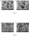
- metal catalysts can be also used in the present induction thermal plasma process for an effective synthesis of BNNTs ( Fig. 3 ).
- nickel Ni, 99.5%, ⁇ 1 ⁇ m particle size
- a metal catalyst Ni, 99.5%, ⁇ 1 ⁇ m particle size
- h-BN powder 99.5%, avg. particle size of 70 nm, MK-hBN-N70, M K Impex Corp.
- nickel was chosen as a feedstock.
- the as-received h-BN powder was well mixed with Ni using a rotary mixer at 60 rpm for 4 hours. Then the mixture was sieved (300 ⁇ m) with a brush and baked at 100°C overnight. The final catalyst concentration of the mixture was 2.0 at.%.
- the reaction chamber included a graphite liner (80 mm id, 125 mm od and 1000 mm length, SIGRAFORM ® HLM, SGL Carbon Group) surrounded by thermal insulatingcarbon felt, in order to extend the high temperature zone desired for the growth of BNNTs.
- a graphite liner 80 mm id, 125 mm od and 1000 mm length, SIGRAFORM ® HLM, SGL Carbon Group
- the temperature inside the reactor was stabilized using argon-nitrogen-hydrogen plasma for an hour.
- the plasma operating conditions were: a ternary gas mixture of 90-slpm Ar, 3-slpm H 2 gas and 10-slpm N 2 in the sheath gas; 30-slpm of Ar in the central gas; 3-slpm of Ar in the carrier gas; 50 kW of plate power; and, 92 kPa (0.91 atm) of reactor pressure.
- the plasma operating conditions were changed for the BNNTs synthesis as follows: a ternary gas mixture of 45-slpm Ar, 55-slpm N 2 gas and 20-slpm H 2 in the sheath gas; 30-slpm of Ar in the central gas; 3-slpm of Ar in the carrier gas; 50 kW of plate power; and, 92 kPa (0.91 atm) of reactor pressure.
- the feedstock was continuously released from a powder feeder (KT20 twin-screw microfeeder, K-Tron, Inc.) with a feed rate of about 0.5 g/min and delivered to the injection probe located on the top of the torch using 3-slpm of Ar carrier gas.
- a powder feeder KT20 twin-screw microfeeder, K-Tron, Inc.
- BNNT material After a 3-hour operation under these conditions, a total of 20.0 g of BNNT material was recovered and the product comprises two different materials: a rubbery cloth-like material and an entangled fibril-like material. Due to light contamination by partially crystallized B by-product, the as-grown material was dark gray rather than snow-white.
- Example 2b h-BN-Ni Mixture Using Argon-Nitrogen-Hydrogen Plasma at a Pressure of 92 kPa (0.91 atm)
- Example 2a Another test was conducted following the same procedure as described in Example 2a except that the plasma operating conditions were chnaged.
- the ternary gas mixture in the sheath gas prior to feeding the feedstock used 110 slpm Ar instead of 90 slpm.
- the ternary gas mixture in the sheath gas after the stabilization period was changed to use 25 slpm Ar instead of 45 slpm and 30 slpm H 2 instead of 20 slpm. This resulted in a recovery of 60.0 g of BNNT instead of only 20.0 g.
- Example 3a h-BN Powder Using Argon-Nitrogen-Ammonia Plasma at a Pressure of 66 kPa (0.65 atm)
- Pure h-BN powder (99.5%, avg. particle size 70 nm, MK-hBN-N70, M K Impex Corp.) was chosen as a feedstock.
- the as-received h-BN powder was sieved (300 ⁇ m) with a brush and baked at 100°C overnight. No metallic catalyst was employed.
- the reaction chamber included a graphite liner (80 mm id, 125 mm od and 1000 mm length, SIGRAFORM ® HLM, SGL Carbon Group) surrounded by thermal insulating carbon felt, in order to extend the high temperature zone desired for the growth of BNNTs.
- a graphite liner 80 mm id, 125 mm od and 1000 mm length, SIGRAFORM ® HLM, SGL Carbon Group
- the temperature inside reactor was stabilized using argon-nitrogen-hydrogen plasma for an hour.
- the plasma operating conditions were: a ternary gas mixture of 90-slpm Ar, 3-slpm H 2 gas and 10-slpm N 2 in the sheath gas; 30-slpm of Ar in the central gas; 3-slpm of Ar in the carrier gas; 50 kW of plate power; and, 66 kPa (0.65 atm) of reactor pressure.
- the plasma operating conditions were changed for the BNNTs synthesis as follows: a ternary gas mixture of 55-slpm Ar, 55-slpm N 2 gas and 10-slpm NH 3 gas in the sheath gas; 30-slpm of Ar in the central gas; 3-slpm of Ar in the carrier gas; 50 kW of plate power; and, 66 kPa (0.65 atm) of reactor pressure.
- the feedstock was continuously released from a powder feeder (KT20 twin-screw microfeeder, K-Tron, Inc.) with a feed rate of about 0.5 g/min and delivered to the injection probe located on the top of the torch using 3-slpm of Ar carrier gas.
- a powder feeder KT20 twin-screw microfeeder, K-Tron, Inc.
- BNNT material After a 3-hour operation under these conditions, a total of 20.0 g of BNNT material was recovered and the product comprises two different materials: a rubbery cloth-like material and an entangled fibril-like material. Due to light contamination by amorphous B by-product, the as-grown material was light-beige rather than snow-white.
- Example 3b h-BN Powder Using Argon-Nitrogen-Ammonia Plasma at a Pressure of 66 kPa (0.65 atm)
- BNNT materials produced with prior art processes are limited to deposits scraped from the reactor walls or cotton-like fibrils.
- real applications or scientific investigation of as-produced materials may require materials in various forms.
- BNNT materials formed in the processes described above show a great diversity in morphology.
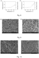
- the present process can produce BNNT materials with several different morphologies in the same run, including i) laminated flexible cloth-like materials on the surfaces of filters ( Fig. 4 ), ii) fibril-like materials on the top of filters ( Fig. 5 ), and iii) thin transparent films on the walls of the pipe between the reactor and the filtration chamber ( Fig. 6 ).
- the cloth-like material (20 cm ⁇ 50 cm) is flexible and mechanically strong which would be ideal for direct uses in manufacturing macroscopic-scale smart materials for civil or mechanical applications.
- This material is composed of multiple layers where thin membranes can be easily peeled off as shown in Fig. 4(a).
- Fig. 4(b) presents a scanning electron microscope (SEM) image of this material. The purity seems to be reasonably high (over 50%), even though non-tubular impurities are present in the samples.
- the length of BNNTs is estimated few ⁇ m.
- Fiber or yarn is one of the attractive forms of functional nano-materials.
- macroscopic BNNT yarns have never been tested for their mechanical properties due to the absence of reliable fabrication methods.
- macroscopic-long fibers can be directly drawn from the fibril-like material simply by pulling them out as shown in Fig. 5(b) .
- the purity of the fibril-like material seems be much higher than that of the cloth-like material.
- a large quantity of fibrous material is observed in the SEM image of this material with less non-tubular impurities ( Fig. 5(d) ).
- the purity of the as-produced material is high enough so that spinning fiber directly from the reactor is possible.
- thin transparent BNNT films can be synthesized in-situ without any substrates in the pipe located between the reactor and the filtration chamber.
- This as-grown BNNT film which is stretchable, sticky and highly electrostatic uniformly covers the entire surface of the pipe and seems to be formed by diffusion of BNNTs towards the cold wall by electrostatic or thermophoretic forces.
- This thin film peels off readily from the surfaces and is mechanically strong enough to free-stand without polymer supports as shown in Fig. 6(a) .
- this thin film may be easily transferable to arbitrary surfaces. It is demonstrated that this thin film can be directly transferrable to a quartz disk via one single step of spraying methanol on it.
- TEM images in Fig. 7 confirm that the fibrous materials seen in the SEM images have a tubular structure.
- the majority of the BNNTs are few walled, their diameters being less than 10 nm. Large diameter tubes over 20 nm are not observed throughout the samples.
- the TEM images of tubes also reveal that their structural quality is high without any noticeable defects on the surface of the tube. The structural quality the BNNTs seems to be improved by the high temperature environment of the process.
- EELS electron energy loss spectroscopy
- Fig. 7(c) shows EELS spectra of the BNNTs produced in the present invention.
- the K-shell ionization edges of B and N can be seen in the spectra which confirm that the tubes are composed of both B and N.
- the carbon peak between the two peaks is also observable due to sample contamination, probably from carbon grid.
- thermogravimetry analysis TGA
- the thermal oxidation temperatures of h-BN materials are known to be higher than 1000°C.
- Fig. 8 shows the thermogravimetry (TG) and derivative thermogravimetry (DTG) plots of the fibril-like and cloth-like BNNT materials produced in the present invention. Both materials are stable up to 600°C under air oxidation; however they started to gain weight at 600°C primarily due to the oxidation of amorphous B impurity present in the samples. Since the cloth-like material gained more weight compared to the fibril-like BNNT material, it can be concluded that the cloth-like material contains more amorphous B impurity.
- Example 5a Purification of Boron Nitride Nanotubes by Solution Processing
- h-BN powder as feedstock in this invention allows for a simple and scalable purification process.
- Various material characterizations have identified three major impurities found in the as-produced BNNT materials: i) unreacted h-BN powder; ii) B-containing polymers; and, iii) elemental B.
- Nano-sized h-BN powder and some of the B-containing polymers are readily dispersed in water due to the solvent polarity effect.
- the cloth-like material is washed with NH 4 OH or water, the material retains its cloth-like structure as a result of BNNTs inherent strength, promoting the physical separation of h-BN and some of the B-containing polymers into solution (Fig. 9(a)).
- the remaining beige material contains elemental B and left-over B-containing polymers that can be easily oxidized to boron oxide, which is water soluble.
- the amorphous B was easily oxidized using hot ⁇ 30% H 2 O 2 (Fig. 9(b)).
- the oxidation reaction clearly transformed the material from beige to off-white. After several washings with water, the material appears very white in suspension.
- the purification process only needs water as the sole solvent and hydrogen peroxide as the sole oxidizer providing a green and accessible purifying method.
- Example 5b Purification of Boron Nitride Nanotubes by Air Oxidation
- h-BN powder as feedstock in this invention allows for a simple and scalable purification process.
- Various material characterizations have identified three major impurities found in the as-produced BNNT materials: i) unreacted h-BN powder; ii) B-containing polymers and, iii) elemental B.
- These impurities can be easily removed by a simple three steps process comprising: 1) mulching or fluffing the raw materials using a mulcher; 2) air oxidation at a temperature in a range of 650°C to 850°C; and, 3) removal of boron oxides, unreacted h-BN and derivatives thereof using water or methanol as solvents and filtration.
- the collected solid material is highly pure BNNT material.
Landscapes
- Engineering & Computer Science (AREA)
- Chemical & Material Sciences (AREA)
- Organic Chemistry (AREA)
- Inorganic Chemistry (AREA)
- Nanotechnology (AREA)
- Physics & Mathematics (AREA)
- General Physics & Mathematics (AREA)
- Signal Processing (AREA)
- Theoretical Computer Science (AREA)
- Human Computer Interaction (AREA)
- Computer Networks & Wireless Communication (AREA)
- General Engineering & Computer Science (AREA)
- Condensed Matter Physics & Semiconductors (AREA)
- Crystallography & Structural Chemistry (AREA)
- Materials Engineering (AREA)
- Composite Materials (AREA)
- Catalysts (AREA)
- Carbon And Carbon Compounds (AREA)
- User Interface Of Digital Computer (AREA)
- Manufacturing & Machinery (AREA)
Claims (14)
- Verfahren zur Herstellung von Bornitrid-Nanoröhren (BNNTs), aufweisend das Bereitstellen einer oder mehrerer Quellen von Bor, Stickstoff und Wasserstoff für ein stabiles Radiofrequenz-Induktionsplasma bei einer Temperatur in einem Bereich von 1000 bis 10000 K, um eine Reaktionsmischung aus Bor, Stickstoff und Wasserstoff im Plasma unter einem Druck von mehr als 60795 Pa (0,6 atm) und weniger als 202650 Pa (2 atm) zu bilden, und Abkühlen der Reaktionsmischung zur Bildung von BNNTs, wobei die eine oder mehreren Borquellen elementares Bor, Bornitrid, Boran, Amminboran, Borazin oder eine beliebige Mischung davon umfassen.
- Verfahren nach Anspruch 1, wobei die eine oder mehreren Borquellen hexagonales Bornitrid umfassen.
- Verfahren nach Anspruch 1 oder 2, wobei die eine oder mehreren Stickstoffquellen Bornitrid, N2, NH3, NH4OH, Borazin oder eine beliebige Mischung davon, vorzugsweise eine Mischung von hexagonalem Bornitrid und N2 umfassen.
- Verfahren nach einem der Ansprüche 1 bis 3, wobei die eine oder mehreren Wasserstoffquellen H2, NH3, NH4OH, ein Boran oder eine beliebige Mischung davon umfassen.
- Verfahren nach einem der Ansprüche 1 bis 4, wobei mindestens eine der Stickstoffquellen ein Gas ist und mindestens eine der Wasserstoffquellen ein Gas ist und die Gase dem stabilen Induktionsplasma in einem Hüllgas zugeführt werden, und wobei die mindestens eine Wasserstoffquelle in dem Hüllgas in einer Menge von 5 bis 40 %, vorzugsweise 5 bis 20 % vorhanden ist, und wobei die mindestens eine Stickstoffquelle in dem Hüllgas in einer Menge von 10 bis 95 %, vorzugsweise 35 bis 65 % vorhanden ist.
- Verfahren nach Anspruch 5, wobei das Hüllgas ferner ein Inertgas, vorzugsweise Argon, umfasst.
- Verfahren nach einem der Ansprüche 1 bis 6, wobei der Druck in einem Bereich von 91192 Pa (0,9 atm) bis 101325 Pa (1 atm) liegt.
- Verfahren nach einem der Ansprüche 1 bis 7, wobei die Reaktionsmischung ferner mit einem Metallkatalysator versehen ist, wobei der Metallkatalysator vorzugsweise Nickel, Eisen, Kobalt, Cer, Yttrium, Molybdän oder eine beliebige Mischung davon umfasst.
- Verfahren nach einem der Ansprüche 1 bis 8, wobei die Reaktionsmischung ferner eine Kohlenstoffquelle umfasst und die hergestellten BNNTs mit Kohlenstoff dotiert sind, wobei die Kohlenstoffquelle vorzugsweise graphitischen Kohlenstoff, amorphen Kohlenstoff, Kohlenmonoxid, Kohlendioxid, ein Kohlenwasserstoff oder eine beliebige Mischung davon umfasst.
- Verfahren nach einem der Ansprüche 1 bis 9, wobei die Temperatur in einem Kern des Plasmas in einem Bereich von 7000 bis 9000 K liegt.
- Verfahren nach einem der Ansprüche 1 bis 10, wobei das Abkühlen der Reaktionsmischung das Abkühlen in einer Reaktionszone stromabwärts des stabilen Induktionsplasmas aufweist.
- Verfahren nach einem der Ansprüche 1 bis 11, ferner aufweisend das Sammeln der BNNTs durch Filtration in einer Filtrationszone stromabwärts der Reaktionszone.
- Verfahren nach einem der Ansprüche 1 bis 12, wobei die eine oder mehreren Quellen für Bor und Stickstoff dem stabilen Induktionsplasma kontinuierlich zugeführt werden, um die BNNTs kontinuierlich zu bilden.
- Verfahren nach einem der Ansprüche 1 bis 13, wobei die eine oder mehreren Borquellen als festes Ausgangsmaterial bereitgestellt werden und/oder metallfrei sind.
Applications Claiming Priority (2)
| Application Number | Priority Date | Filing Date | Title |
|---|---|---|---|
| US201361813324P | 2013-04-18 | 2013-04-18 | |
| PCT/CA2014/050340 WO2014169382A1 (en) | 2013-04-18 | 2014-04-04 | Boron nitride nanotubes and process for production thereof |
Publications (3)
| Publication Number | Publication Date |
|---|---|
| EP2986557A1 EP2986557A1 (de) | 2016-02-24 |
| EP2986557A4 EP2986557A4 (de) | 2016-11-02 |
| EP2986557B1 true EP2986557B1 (de) | 2023-03-08 |
Family
ID=51730634
Family Applications (1)
| Application Number | Title | Priority Date | Filing Date |
|---|---|---|---|
| EP14785507.6A Active EP2986557B1 (de) | 2013-04-18 | 2014-04-04 | Verfahren zur herstellung von bornitrid-nanoröhrchen |
Country Status (6)
| Country | Link |
|---|---|
| US (1) | US9862604B2 (de) |
| EP (1) | EP2986557B1 (de) |
| JP (1) | JP6359081B2 (de) |
| KR (1) | KR102307337B1 (de) |
| CA (1) | CA2877060C (de) |
| WO (1) | WO2014169382A1 (de) |
Families Citing this family (28)
| Publication number | Priority date | Publication date | Assignee | Title |
|---|---|---|---|---|
| US10343908B2 (en) | 2013-11-01 | 2019-07-09 | Bnnt, Llc | Induction-coupled plasma synthesis of boron nitrade nanotubes |
| EP3569570A1 (de) | 2014-04-24 | 2019-11-20 | Bnnt, Llc | Kontinuierliche bornitridnanoröhrchenfasern |
| FI3718965T3 (fi) * | 2014-06-25 | 2023-08-30 | Univ California | Järjestelmä ja menetelmiä boorinitridinanorakenteiden valmistamiseksi |
| US9908820B2 (en) * | 2014-09-05 | 2018-03-06 | United Technologies Corporation | Systems and methods for ceramic matrix composites |
| EP3212571B1 (de) | 2014-11-01 | 2019-08-14 | Bnnt, Llc | Verfahren zur herstellung von bornitrid-nanoröhrchen |
| WO2016094660A1 (en) | 2014-12-12 | 2016-06-16 | New Valence Robotics Corporation | Additive manufacturing of metallic structures |
| CA2972769C (en) | 2014-12-17 | 2023-01-03 | Bnnt, Llc | Boron nitride nanotube enhanced electrical components |
| CA2985795C (en) | 2015-05-13 | 2023-11-07 | Bnnt, Llc | Boron nitride nanotube neutron detector |
| JP6705837B2 (ja) | 2015-05-21 | 2020-06-03 | ビイエヌエヌティ・エルエルシイ | 直接誘導による窒化ホウ素ナノチューブ合成 |
| KR101842062B1 (ko) * | 2016-08-03 | 2018-03-26 | 한국과학기술연구원 | 질화붕소 나노튜브의 제조 방법 |
| KR101867905B1 (ko) | 2016-11-14 | 2018-06-18 | 한국과학기술연구원 | 질화붕소 나노튜브 제조 장치 및 이를 이용한 질화붕소 나노튜브 제조 방법 |
| JP7029465B2 (ja) * | 2016-11-29 | 2022-03-03 | ビイエヌエヌティ・エルエルシイ | 窒化ホウ素ナノチューブの精製方法 |
| US20180165265A1 (en) * | 2016-12-08 | 2018-06-14 | International Business Machines Corporation | Indicating property inheritance in object hierarchies |
| US20210087102A1 (en) * | 2017-08-02 | 2021-03-25 | National Research Council Of Canada | Boron nitride nanotube-silicate glass composites |
| JP7215688B2 (ja) * | 2017-09-21 | 2023-01-31 | ナショナル リサーチ カウンシル オブ カナダ | 窒化ホウ素ナノチューブ(bnnt)-ナノ粒子複合材料、その調製方法及びそれらの巨視的集合体 |
| US11613464B2 (en) | 2017-10-27 | 2023-03-28 | National Research Council Of Canada | Modified boron nitride nanotubes and solutions thereof |
| EP3755656A4 (de) | 2018-02-19 | 2021-11-24 | Bnnt, Llc | Bnnt-wärmemanagementmaterialien für hochleistungssysteme |
| KR102209684B1 (ko) | 2018-04-27 | 2021-02-02 | 내일테크놀로지 주식회사 | 표면이 개질된 질화붕소나노구조체 및 이의 제조방법 |
| WO2020010458A1 (en) | 2018-07-11 | 2020-01-16 | National Research Council Of Canada | Process and apparatus for purifying bnnt |
| US11254571B1 (en) | 2019-01-11 | 2022-02-22 | United States Of America As Represented By The Secretary Of The Air Force | Purification and enrichment of boron nitride nanotube feedstocks |
| US11853033B1 (en) | 2019-07-26 | 2023-12-26 | Relativity Space, Inc. | Systems and methods for using wire printing process data to predict material properties and part quality |
| KR102250518B1 (ko) | 2019-08-02 | 2021-05-12 | 한국과학기술연구원 | 질화붕소 나노튜브 연속 제조 장치 및 그 제조방법 |
| KR102143989B1 (ko) * | 2019-10-25 | 2020-08-12 | 재단법인 철원플라즈마 산업기술연구원 | 질화붕소 나노튜브 제조 장치 |
| KR102230032B1 (ko) | 2019-10-28 | 2021-03-19 | 한국과학기술연구원 | 질화붕소 나노튜브 제조 시스템 |
| US20240087759A1 (en) * | 2021-01-25 | 2024-03-14 | Bnnt, Llc | Xenon-enhanced, ammonia borane-filled boron nitride nanotube fusion targets |
| US20240105348A1 (en) * | 2021-01-25 | 2024-03-28 | Bnnt, Llc | Ammonia borane-filled boron nitride nanotube fusion targets |
| CN112831185B (zh) * | 2021-02-23 | 2022-09-20 | 中北大学 | 梯度导电-均匀导热双功能网络低反射高吸收电磁屏蔽聚合物复合材料 |
| KR102618648B1 (ko) * | 2021-08-20 | 2023-12-28 | 한국과학기술연구원 | 보론 나이트라이드 나노튜브의 제조 방법 |
Family Cites Families (14)
| Publication number | Priority date | Publication date | Assignee | Title |
|---|---|---|---|---|
| EP0450125B1 (de) | 1990-04-06 | 1994-10-26 | Siemens Aktiengesellschaft | Verfahren zur Herstellung von mikrokristallin kubischen Bornitridschichten |
| JPH11139821A (ja) * | 1997-11-06 | 1999-05-25 | Natl Inst For Res In Inorg Mater | 多成分系ナノチューブの製造方法 |
| JP2007516314A (ja) * | 2003-05-22 | 2007-06-21 | ザイベックス コーポレーション | ナノコンポジットおよびナノコンポジットに関する方法 |
| CA2500766A1 (en) | 2005-03-14 | 2006-09-14 | National Research Council Of Canada | Method and apparatus for the continuous production and functionalization of single-walled carbon nanotubes using a high frequency induction plasma torch |
| WO2008140583A2 (en) | 2006-11-22 | 2008-11-20 | The Regents Of The University Of California | Functionalized boron nitride nanotubes |
| JP5355423B2 (ja) * | 2007-02-22 | 2013-11-27 | ダウ コーニング コーポレーション | 伝導性フィルムを調製するためのプロセスおよびそのプロセスを用いて調製した物品 |
| US8206674B2 (en) | 2007-05-15 | 2012-06-26 | National Institute Of Aerospace Associates | Boron nitride nanotubes |
| KR101773886B1 (ko) * | 2009-09-21 | 2017-09-01 | 디킨 유니버시티 | 제조 방법 |
| WO2011119494A1 (en) * | 2010-03-22 | 2011-09-29 | The Regents Of The University Of California | Method and device to synthesize boron nitride nanotubes and related nanoparticles |
| EP2567385A1 (de) * | 2010-05-07 | 2013-03-13 | National Institute Of Aerospace Associates | Boronnitrid und strahlungsabschirmungsmaterialien aus boronnitrid-nanoröhrchen |
| JP5704640B2 (ja) * | 2011-01-25 | 2015-04-22 | 国立大学法人長岡技術科学大学 | 金属担持窒化ホウ素ナノ構造体及びその製造方法 |
| BRPI1104516B1 (pt) | 2011-09-16 | 2021-03-02 | Universidade Estadual De Campinas - Unicamp | processo de transformação bacteriana utilizando nanotubos de nitreto de boro |
| US9963345B2 (en) | 2013-03-15 | 2018-05-08 | The United States Of America As Represented By The Administrator Of Nasa | Nanoparticle hybrid composites by RF plasma spray deposition |
| US10343908B2 (en) | 2013-11-01 | 2019-07-09 | Bnnt, Llc | Induction-coupled plasma synthesis of boron nitrade nanotubes |
-
2014
- 2014-04-04 JP JP2016507961A patent/JP6359081B2/ja active Active
- 2014-04-04 KR KR1020157032760A patent/KR102307337B1/ko active IP Right Grant
- 2014-04-04 CA CA2877060A patent/CA2877060C/en active Active
- 2014-04-04 WO PCT/CA2014/050340 patent/WO2014169382A1/en active Application Filing
- 2014-04-04 US US14/409,128 patent/US9862604B2/en active Active
- 2014-04-04 EP EP14785507.6A patent/EP2986557B1/de active Active
Also Published As
| Publication number | Publication date |
|---|---|
| US9862604B2 (en) | 2018-01-09 |
| WO2014169382A1 (en) | 2014-10-23 |
| KR20150143798A (ko) | 2015-12-23 |
| EP2986557A1 (de) | 2016-02-24 |
| KR102307337B1 (ko) | 2021-10-01 |
| EP2986557A4 (de) | 2016-11-02 |
| US20160083253A1 (en) | 2016-03-24 |
| JP6359081B2 (ja) | 2018-07-18 |
| JP2016521240A (ja) | 2016-07-21 |
| CA2877060A1 (en) | 2014-10-23 |
| CA2877060C (en) | 2015-07-28 |
| US20170253485A2 (en) | 2017-09-07 |
| US20170152142A9 (en) | 2017-06-01 |
Similar Documents
| Publication | Publication Date | Title |
|---|---|---|
| EP2986557B1 (de) | Verfahren zur herstellung von bornitrid-nanoröhrchen | |
| EP2459484B1 (de) | Herstellung von graphen aus metallalkoxid | |
| US20220281743A1 (en) | System and methods for fabricating boron nitride nanostructures | |
| US20060269669A1 (en) | Apparatus and method for making carbon nanotube array | |
| WO2011119494A1 (en) | Method and device to synthesize boron nitride nanotubes and related nanoparticles | |
| JP4443423B2 (ja) | 単層カーボンナノチューブの製造方法および製造装置 | |
| WO2009051888A1 (en) | Doped ultrafine metal carbide particles | |
| WO2012068781A1 (en) | System and method for producing hydrogen gas | |
| Kim et al. | Growth of Sb2O3 submicron rods by the thermal evaporation of a mixture of Zn and Sb powders | |
| CN110040720A (zh) | 高纯度、窄直径分布、小直径双壁碳纳米管的制备方法 | |
| KR20160049093A (ko) | 열플라즈마를 이용한 입방질화붕소 나노분말의 제조방법 및 이에 따라 제조되는 입방질화붕소 나노분말 | |
| Zaharieva et al. | Plasma-chemical synthesis of nanosized powders-nitrides, carbides, oxides, carbon nanotubes and fullerenes | |
| KIM et al. | Patent 2877060 Summary | |
| Guo et al. | Mechanochemical formation of novel catalyst for preparing carbon nanotubes: nanocrystalline yttrium aluminum iron perovskite | |
| Khavarian et al. | Floating catalyst CVD synthesis of carbon nanotubes using iron (III) chloride: Influences of the growth parameters | |
| US20230406705A1 (en) | Method for producing boron nitride nanotubes | |
| Chen et al. | Boron Nitride Nanotube and Nanosheet Synthesis by Flash Joule Heating | |
| JP2005350308A (ja) | カーボンナノチューブおよびその製造方法 | |
| Bhartiya et al. | Synthesis methods of nanotubes | |
| Mansurov | Nanomaterials synthesis in combustion | |
| Zhang | Study on the synthesis process of carbon nanotubes |
Legal Events
| Date | Code | Title | Description |
|---|---|---|---|
| PUAI | Public reference made under article 153(3) epc to a published international application that has entered the european phase |
Free format text: ORIGINAL CODE: 0009012 |
|
| 17P | Request for examination filed |
Effective date: 20151118 |
|
| AK | Designated contracting states |
Kind code of ref document: A1 Designated state(s): AL AT BE BG CH CY CZ DE DK EE ES FI FR GB GR HR HU IE IS IT LI LT LU LV MC MK MT NL NO PL PT RO RS SE SI SK SM TR |
|
| AX | Request for extension of the european patent |
Extension state: BA ME |
|
| DAX | Request for extension of the european patent (deleted) | ||
| A4 | Supplementary search report drawn up and despatched |
Effective date: 20161006 |
|
| RIC1 | Information provided on ipc code assigned before grant |
Ipc: B82Y 30/00 20110101ALI20160929BHEP Ipc: C01B 21/064 20060101AFI20160929BHEP Ipc: B82Y 40/00 20110101ALI20160929BHEP |
|
| STAA | Information on the status of an ep patent application or granted ep patent |
Free format text: STATUS: EXAMINATION IS IN PROGRESS |
|
| 17Q | First examination report despatched |
Effective date: 20180416 |
|
| STAA | Information on the status of an ep patent application or granted ep patent |
Free format text: STATUS: EXAMINATION IS IN PROGRESS |
|
| STAA | Information on the status of an ep patent application or granted ep patent |
Free format text: STATUS: EXAMINATION IS IN PROGRESS |
|
| GRAP | Despatch of communication of intention to grant a patent |
Free format text: ORIGINAL CODE: EPIDOSNIGR1 |
|
| STAA | Information on the status of an ep patent application or granted ep patent |
Free format text: STATUS: GRANT OF PATENT IS INTENDED |
|
| RIC1 | Information provided on ipc code assigned before grant |
Ipc: H04L 41/22 20220101ALI20220901BHEP Ipc: H04L 41/0813 20220101ALI20220901BHEP Ipc: G06F 3/0484 20130101ALI20220901BHEP Ipc: H04L 9/40 20220101ALI20220901BHEP Ipc: B82Y 40/00 20110101ALI20220901BHEP Ipc: B82Y 30/00 20110101ALI20220901BHEP Ipc: C01B 21/064 20060101AFI20220901BHEP |
|
| INTG | Intention to grant announced |
Effective date: 20220930 |
|
| RIN1 | Information on inventor provided before grant (corrected) |
Inventor name: KINGSTON, CHRISTOPHER T. Inventor name: KIM, KEUN SU Inventor name: SIMARD, BENOIT |
|
| GRAS | Grant fee paid |
Free format text: ORIGINAL CODE: EPIDOSNIGR3 |
|
| GRAA | (expected) grant |
Free format text: ORIGINAL CODE: 0009210 |
|
| STAA | Information on the status of an ep patent application or granted ep patent |
Free format text: STATUS: THE PATENT HAS BEEN GRANTED |
|
| AK | Designated contracting states |
Kind code of ref document: B1 Designated state(s): AL AT BE BG CH CY CZ DE DK EE ES FI FR GB GR HR HU IE IS IT LI LT LU LV MC MK MT NL NO PL PT RO RS SE SI SK SM TR |
|
| REG | Reference to a national code |
Ref country code: GB Ref legal event code: FG4D |
|
| REG | Reference to a national code |
Ref country code: CH Ref legal event code: EP Ref country code: AT Ref legal event code: REF Ref document number: 1552484 Country of ref document: AT Kind code of ref document: T Effective date: 20230315 |
|
| REG | Reference to a national code |
Ref country code: IE Ref legal event code: FG4D |
|
| REG | Reference to a national code |
Ref country code: DE Ref legal event code: R096 Ref document number: 602014086420 Country of ref document: DE |
|
| REG | Reference to a national code |
Ref country code: LT Ref legal event code: MG9D |
|
| REG | Reference to a national code |
Ref country code: NL Ref legal event code: MP Effective date: 20230308 |
|
| PG25 | Lapsed in a contracting state [announced via postgrant information from national office to epo] |
Ref country code: RS Free format text: LAPSE BECAUSE OF FAILURE TO SUBMIT A TRANSLATION OF THE DESCRIPTION OR TO PAY THE FEE WITHIN THE PRESCRIBED TIME-LIMIT Effective date: 20230308 Ref country code: NO Free format text: LAPSE BECAUSE OF FAILURE TO SUBMIT A TRANSLATION OF THE DESCRIPTION OR TO PAY THE FEE WITHIN THE PRESCRIBED TIME-LIMIT Effective date: 20230608 Ref country code: LV Free format text: LAPSE BECAUSE OF FAILURE TO SUBMIT A TRANSLATION OF THE DESCRIPTION OR TO PAY THE FEE WITHIN THE PRESCRIBED TIME-LIMIT Effective date: 20230308 Ref country code: LT Free format text: LAPSE BECAUSE OF FAILURE TO SUBMIT A TRANSLATION OF THE DESCRIPTION OR TO PAY THE FEE WITHIN THE PRESCRIBED TIME-LIMIT Effective date: 20230308 Ref country code: HR Free format text: LAPSE BECAUSE OF FAILURE TO SUBMIT A TRANSLATION OF THE DESCRIPTION OR TO PAY THE FEE WITHIN THE PRESCRIBED TIME-LIMIT Effective date: 20230308 Ref country code: ES Free format text: LAPSE BECAUSE OF FAILURE TO SUBMIT A TRANSLATION OF THE DESCRIPTION OR TO PAY THE FEE WITHIN THE PRESCRIBED TIME-LIMIT Effective date: 20230308 |
|
| PGFP | Annual fee paid to national office [announced via postgrant information from national office to epo] |
Ref country code: FR Payment date: 20230525 Year of fee payment: 10 Ref country code: DE Payment date: 20230530 Year of fee payment: 10 |
|
| REG | Reference to a national code |
Ref country code: AT Ref legal event code: MK05 Ref document number: 1552484 Country of ref document: AT Kind code of ref document: T Effective date: 20230308 |
|
| PG25 | Lapsed in a contracting state [announced via postgrant information from national office to epo] |
Ref country code: SE Free format text: LAPSE BECAUSE OF FAILURE TO SUBMIT A TRANSLATION OF THE DESCRIPTION OR TO PAY THE FEE WITHIN THE PRESCRIBED TIME-LIMIT Effective date: 20230308 Ref country code: NL Free format text: LAPSE BECAUSE OF FAILURE TO SUBMIT A TRANSLATION OF THE DESCRIPTION OR TO PAY THE FEE WITHIN THE PRESCRIBED TIME-LIMIT Effective date: 20230308 Ref country code: GR Free format text: LAPSE BECAUSE OF FAILURE TO SUBMIT A TRANSLATION OF THE DESCRIPTION OR TO PAY THE FEE WITHIN THE PRESCRIBED TIME-LIMIT Effective date: 20230609 Ref country code: FI Free format text: LAPSE BECAUSE OF FAILURE TO SUBMIT A TRANSLATION OF THE DESCRIPTION OR TO PAY THE FEE WITHIN THE PRESCRIBED TIME-LIMIT Effective date: 20230308 |
|
| PG25 | Lapsed in a contracting state [announced via postgrant information from national office to epo] |
Ref country code: SM Free format text: LAPSE BECAUSE OF FAILURE TO SUBMIT A TRANSLATION OF THE DESCRIPTION OR TO PAY THE FEE WITHIN THE PRESCRIBED TIME-LIMIT Effective date: 20230308 Ref country code: RO Free format text: LAPSE BECAUSE OF FAILURE TO SUBMIT A TRANSLATION OF THE DESCRIPTION OR TO PAY THE FEE WITHIN THE PRESCRIBED TIME-LIMIT Effective date: 20230308 Ref country code: PT Free format text: LAPSE BECAUSE OF FAILURE TO SUBMIT A TRANSLATION OF THE DESCRIPTION OR TO PAY THE FEE WITHIN THE PRESCRIBED TIME-LIMIT Effective date: 20230710 Ref country code: EE Free format text: LAPSE BECAUSE OF FAILURE TO SUBMIT A TRANSLATION OF THE DESCRIPTION OR TO PAY THE FEE WITHIN THE PRESCRIBED TIME-LIMIT Effective date: 20230308 Ref country code: CZ Free format text: LAPSE BECAUSE OF FAILURE TO SUBMIT A TRANSLATION OF THE DESCRIPTION OR TO PAY THE FEE WITHIN THE PRESCRIBED TIME-LIMIT Effective date: 20230308 Ref country code: AT Free format text: LAPSE BECAUSE OF FAILURE TO SUBMIT A TRANSLATION OF THE DESCRIPTION OR TO PAY THE FEE WITHIN THE PRESCRIBED TIME-LIMIT Effective date: 20230308 |
|
| PGFP | Annual fee paid to national office [announced via postgrant information from national office to epo] |
Ref country code: GB Payment date: 20230524 Year of fee payment: 10 |
|
| PG25 | Lapsed in a contracting state [announced via postgrant information from national office to epo] |
Ref country code: SK Free format text: LAPSE BECAUSE OF FAILURE TO SUBMIT A TRANSLATION OF THE DESCRIPTION OR TO PAY THE FEE WITHIN THE PRESCRIBED TIME-LIMIT Effective date: 20230308 Ref country code: PL Free format text: LAPSE BECAUSE OF FAILURE TO SUBMIT A TRANSLATION OF THE DESCRIPTION OR TO PAY THE FEE WITHIN THE PRESCRIBED TIME-LIMIT Effective date: 20230308 Ref country code: IS Free format text: LAPSE BECAUSE OF FAILURE TO SUBMIT A TRANSLATION OF THE DESCRIPTION OR TO PAY THE FEE WITHIN THE PRESCRIBED TIME-LIMIT Effective date: 20230708 |
|
| REG | Reference to a national code |
Ref country code: CH Ref legal event code: PL |
|
| REG | Reference to a national code |
Ref country code: DE Ref legal event code: R097 Ref document number: 602014086420 Country of ref document: DE |
|
| PG25 | Lapsed in a contracting state [announced via postgrant information from national office to epo] |
Ref country code: LU Free format text: LAPSE BECAUSE OF NON-PAYMENT OF DUE FEES Effective date: 20230404 |
|
| REG | Reference to a national code |
Ref country code: BE Ref legal event code: MM Effective date: 20230430 |
|
| PLBE | No opposition filed within time limit |
Free format text: ORIGINAL CODE: 0009261 |
|
| STAA | Information on the status of an ep patent application or granted ep patent |
Free format text: STATUS: NO OPPOSITION FILED WITHIN TIME LIMIT |
|
| PG25 | Lapsed in a contracting state [announced via postgrant information from national office to epo] |
Ref country code: MC Free format text: LAPSE BECAUSE OF FAILURE TO SUBMIT A TRANSLATION OF THE DESCRIPTION OR TO PAY THE FEE WITHIN THE PRESCRIBED TIME-LIMIT Effective date: 20230308 |
|
| PG25 | Lapsed in a contracting state [announced via postgrant information from national office to epo] |
Ref country code: SI Free format text: LAPSE BECAUSE OF FAILURE TO SUBMIT A TRANSLATION OF THE DESCRIPTION OR TO PAY THE FEE WITHIN THE PRESCRIBED TIME-LIMIT Effective date: 20230308 Ref country code: MC Free format text: LAPSE BECAUSE OF FAILURE TO SUBMIT A TRANSLATION OF THE DESCRIPTION OR TO PAY THE FEE WITHIN THE PRESCRIBED TIME-LIMIT Effective date: 20230308 Ref country code: LI Free format text: LAPSE BECAUSE OF NON-PAYMENT OF DUE FEES Effective date: 20230430 Ref country code: DK Free format text: LAPSE BECAUSE OF FAILURE TO SUBMIT A TRANSLATION OF THE DESCRIPTION OR TO PAY THE FEE WITHIN THE PRESCRIBED TIME-LIMIT Effective date: 20230308 Ref country code: CH Free format text: LAPSE BECAUSE OF NON-PAYMENT OF DUE FEES Effective date: 20230430 |
|
| 26N | No opposition filed |
Effective date: 20231211 |
|
| REG | Reference to a national code |
Ref country code: IE Ref legal event code: MM4A |
|
| PG25 | Lapsed in a contracting state [announced via postgrant information from national office to epo] |
Ref country code: BE Free format text: LAPSE BECAUSE OF NON-PAYMENT OF DUE FEES Effective date: 20230430 |
|
| PG25 | Lapsed in a contracting state [announced via postgrant information from national office to epo] |
Ref country code: IE Free format text: LAPSE BECAUSE OF NON-PAYMENT OF DUE FEES Effective date: 20230404 |
|
| PG25 | Lapsed in a contracting state [announced via postgrant information from national office to epo] |
Ref country code: IE Free format text: LAPSE BECAUSE OF NON-PAYMENT OF DUE FEES Effective date: 20230404 |