EP2984685B1 - Fabrication method for top emitting semiconductor light emitting devices - Google Patents
Fabrication method for top emitting semiconductor light emitting devices Download PDFInfo
- Publication number
- EP2984685B1 EP2984685B1 EP14716970.0A EP14716970A EP2984685B1 EP 2984685 B1 EP2984685 B1 EP 2984685B1 EP 14716970 A EP14716970 A EP 14716970A EP 2984685 B1 EP2984685 B1 EP 2984685B1
- Authority
- EP
- European Patent Office
- Prior art keywords
- light emitting
- leds
- semiconductor light
- emitting devices
- wavelength converting
- Prior art date
- Legal status (The legal status is an assumption and is not a legal conclusion. Google has not performed a legal analysis and makes no representation as to the accuracy of the status listed.)
- Active
Links
Images
Classifications
-
- H—ELECTRICITY
- H01—ELECTRIC ELEMENTS
- H01L—SEMICONDUCTOR DEVICES NOT COVERED BY CLASS H10
- H01L33/00—Semiconductor devices with at least one potential-jump barrier or surface barrier specially adapted for light emission; Processes or apparatus specially adapted for the manufacture or treatment thereof or of parts thereof; Details thereof
- H01L33/02—Semiconductor devices with at least one potential-jump barrier or surface barrier specially adapted for light emission; Processes or apparatus specially adapted for the manufacture or treatment thereof or of parts thereof; Details thereof characterised by the semiconductor bodies
- H01L33/20—Semiconductor devices with at least one potential-jump barrier or surface barrier specially adapted for light emission; Processes or apparatus specially adapted for the manufacture or treatment thereof or of parts thereof; Details thereof characterised by the semiconductor bodies with a particular shape, e.g. curved or truncated substrate
-
- H—ELECTRICITY
- H01—ELECTRIC ELEMENTS
- H01L—SEMICONDUCTOR DEVICES NOT COVERED BY CLASS H10
- H01L25/00—Assemblies consisting of a plurality of individual semiconductor or other solid state devices ; Multistep manufacturing processes thereof
- H01L25/03—Assemblies consisting of a plurality of individual semiconductor or other solid state devices ; Multistep manufacturing processes thereof all the devices being of a type provided for in the same subgroup of groups H01L27/00 - H01L33/00, or in a single subclass of H10K, H10N, e.g. assemblies of rectifier diodes
- H01L25/04—Assemblies consisting of a plurality of individual semiconductor or other solid state devices ; Multistep manufacturing processes thereof all the devices being of a type provided for in the same subgroup of groups H01L27/00 - H01L33/00, or in a single subclass of H10K, H10N, e.g. assemblies of rectifier diodes the devices not having separate containers
- H01L25/075—Assemblies consisting of a plurality of individual semiconductor or other solid state devices ; Multistep manufacturing processes thereof all the devices being of a type provided for in the same subgroup of groups H01L27/00 - H01L33/00, or in a single subclass of H10K, H10N, e.g. assemblies of rectifier diodes the devices not having separate containers the devices being of a type provided for in group H01L33/00
- H01L25/0753—Assemblies consisting of a plurality of individual semiconductor or other solid state devices ; Multistep manufacturing processes thereof all the devices being of a type provided for in the same subgroup of groups H01L27/00 - H01L33/00, or in a single subclass of H10K, H10N, e.g. assemblies of rectifier diodes the devices not having separate containers the devices being of a type provided for in group H01L33/00 the devices being arranged next to each other
-
- H—ELECTRICITY
- H01—ELECTRIC ELEMENTS
- H01L—SEMICONDUCTOR DEVICES NOT COVERED BY CLASS H10
- H01L33/00—Semiconductor devices with at least one potential-jump barrier or surface barrier specially adapted for light emission; Processes or apparatus specially adapted for the manufacture or treatment thereof or of parts thereof; Details thereof
- H01L33/005—Processes
- H01L33/0062—Processes for devices with an active region comprising only III-V compounds
- H01L33/0066—Processes for devices with an active region comprising only III-V compounds with a substrate not being a III-V compound
- H01L33/007—Processes for devices with an active region comprising only III-V compounds with a substrate not being a III-V compound comprising nitride compounds
-
- H—ELECTRICITY
- H01—ELECTRIC ELEMENTS
- H01L—SEMICONDUCTOR DEVICES NOT COVERED BY CLASS H10
- H01L33/00—Semiconductor devices with at least one potential-jump barrier or surface barrier specially adapted for light emission; Processes or apparatus specially adapted for the manufacture or treatment thereof or of parts thereof; Details thereof
- H01L33/005—Processes
- H01L33/0093—Wafer bonding; Removal of the growth substrate
-
- H—ELECTRICITY
- H01—ELECTRIC ELEMENTS
- H01L—SEMICONDUCTOR DEVICES NOT COVERED BY CLASS H10
- H01L33/00—Semiconductor devices with at least one potential-jump barrier or surface barrier specially adapted for light emission; Processes or apparatus specially adapted for the manufacture or treatment thereof or of parts thereof; Details thereof
- H01L33/02—Semiconductor devices with at least one potential-jump barrier or surface barrier specially adapted for light emission; Processes or apparatus specially adapted for the manufacture or treatment thereof or of parts thereof; Details thereof characterised by the semiconductor bodies
- H01L33/04—Semiconductor devices with at least one potential-jump barrier or surface barrier specially adapted for light emission; Processes or apparatus specially adapted for the manufacture or treatment thereof or of parts thereof; Details thereof characterised by the semiconductor bodies with a quantum effect structure or superlattice, e.g. tunnel junction
- H01L33/06—Semiconductor devices with at least one potential-jump barrier or surface barrier specially adapted for light emission; Processes or apparatus specially adapted for the manufacture or treatment thereof or of parts thereof; Details thereof characterised by the semiconductor bodies with a quantum effect structure or superlattice, e.g. tunnel junction within the light emitting region, e.g. quantum confinement structure or tunnel barrier
-
- H—ELECTRICITY
- H01—ELECTRIC ELEMENTS
- H01L—SEMICONDUCTOR DEVICES NOT COVERED BY CLASS H10
- H01L33/00—Semiconductor devices with at least one potential-jump barrier or surface barrier specially adapted for light emission; Processes or apparatus specially adapted for the manufacture or treatment thereof or of parts thereof; Details thereof
- H01L33/02—Semiconductor devices with at least one potential-jump barrier or surface barrier specially adapted for light emission; Processes or apparatus specially adapted for the manufacture or treatment thereof or of parts thereof; Details thereof characterised by the semiconductor bodies
- H01L33/26—Materials of the light emitting region
- H01L33/30—Materials of the light emitting region containing only elements of group III and group V of the periodic system
- H01L33/32—Materials of the light emitting region containing only elements of group III and group V of the periodic system containing nitrogen
-
- H—ELECTRICITY
- H01—ELECTRIC ELEMENTS
- H01L—SEMICONDUCTOR DEVICES NOT COVERED BY CLASS H10
- H01L33/00—Semiconductor devices with at least one potential-jump barrier or surface barrier specially adapted for light emission; Processes or apparatus specially adapted for the manufacture or treatment thereof or of parts thereof; Details thereof
- H01L33/44—Semiconductor devices with at least one potential-jump barrier or surface barrier specially adapted for light emission; Processes or apparatus specially adapted for the manufacture or treatment thereof or of parts thereof; Details thereof characterised by the coatings, e.g. passivation layer or anti-reflective coating
- H01L33/46—Reflective coating, e.g. dielectric Bragg reflector
- H01L33/465—Reflective coating, e.g. dielectric Bragg reflector with a resonant cavity structure
-
- H—ELECTRICITY
- H01—ELECTRIC ELEMENTS
- H01L—SEMICONDUCTOR DEVICES NOT COVERED BY CLASS H10
- H01L33/00—Semiconductor devices with at least one potential-jump barrier or surface barrier specially adapted for light emission; Processes or apparatus specially adapted for the manufacture or treatment thereof or of parts thereof; Details thereof
- H01L33/48—Semiconductor devices with at least one potential-jump barrier or surface barrier specially adapted for light emission; Processes or apparatus specially adapted for the manufacture or treatment thereof or of parts thereof; Details thereof characterised by the semiconductor body packages
- H01L33/50—Wavelength conversion elements
- H01L33/501—Wavelength conversion elements characterised by the materials, e.g. binder
- H01L33/502—Wavelength conversion materials
-
- H—ELECTRICITY
- H01—ELECTRIC ELEMENTS
- H01L—SEMICONDUCTOR DEVICES NOT COVERED BY CLASS H10
- H01L33/00—Semiconductor devices with at least one potential-jump barrier or surface barrier specially adapted for light emission; Processes or apparatus specially adapted for the manufacture or treatment thereof or of parts thereof; Details thereof
- H01L33/48—Semiconductor devices with at least one potential-jump barrier or surface barrier specially adapted for light emission; Processes or apparatus specially adapted for the manufacture or treatment thereof or of parts thereof; Details thereof characterised by the semiconductor body packages
- H01L33/52—Encapsulations
- H01L33/56—Materials, e.g. epoxy or silicone resin
-
- H—ELECTRICITY
- H01—ELECTRIC ELEMENTS
- H01L—SEMICONDUCTOR DEVICES NOT COVERED BY CLASS H10
- H01L33/00—Semiconductor devices with at least one potential-jump barrier or surface barrier specially adapted for light emission; Processes or apparatus specially adapted for the manufacture or treatment thereof or of parts thereof; Details thereof
- H01L33/48—Semiconductor devices with at least one potential-jump barrier or surface barrier specially adapted for light emission; Processes or apparatus specially adapted for the manufacture or treatment thereof or of parts thereof; Details thereof characterised by the semiconductor body packages
- H01L33/62—Arrangements for conducting electric current to or from the semiconductor body, e.g. lead-frames, wire-bonds or solder balls
-
- H—ELECTRICITY
- H01—ELECTRIC ELEMENTS
- H01L—SEMICONDUCTOR DEVICES NOT COVERED BY CLASS H10
- H01L2933/00—Details relating to devices covered by the group H01L33/00 but not provided for in its subgroups
- H01L2933/0008—Processes
- H01L2933/0025—Processes relating to coatings
-
- H—ELECTRICITY
- H01—ELECTRIC ELEMENTS
- H01L—SEMICONDUCTOR DEVICES NOT COVERED BY CLASS H10
- H01L2933/00—Details relating to devices covered by the group H01L33/00 but not provided for in its subgroups
- H01L2933/0008—Processes
- H01L2933/0033—Processes relating to semiconductor body packages
- H01L2933/0041—Processes relating to semiconductor body packages relating to wavelength conversion elements
-
- H—ELECTRICITY
- H01—ELECTRIC ELEMENTS
- H01L—SEMICONDUCTOR DEVICES NOT COVERED BY CLASS H10
- H01L2933/00—Details relating to devices covered by the group H01L33/00 but not provided for in its subgroups
- H01L2933/0008—Processes
- H01L2933/0033—Processes relating to semiconductor body packages
- H01L2933/005—Processes relating to semiconductor body packages relating to encapsulations
-
- H—ELECTRICITY
- H01—ELECTRIC ELEMENTS
- H01L—SEMICONDUCTOR DEVICES NOT COVERED BY CLASS H10
- H01L2933/00—Details relating to devices covered by the group H01L33/00 but not provided for in its subgroups
- H01L2933/0008—Processes
- H01L2933/0033—Processes relating to semiconductor body packages
- H01L2933/0066—Processes relating to semiconductor body packages relating to arrangements for conducting electric current to or from the semiconductor body
-
- H—ELECTRICITY
- H01—ELECTRIC ELEMENTS
- H01L—SEMICONDUCTOR DEVICES NOT COVERED BY CLASS H10
- H01L2933/00—Details relating to devices covered by the group H01L33/00 but not provided for in its subgroups
- H01L2933/0091—Scattering means in or on the semiconductor body or semiconductor body package
-
- H—ELECTRICITY
- H01—ELECTRIC ELEMENTS
- H01L—SEMICONDUCTOR DEVICES NOT COVERED BY CLASS H10
- H01L33/00—Semiconductor devices with at least one potential-jump barrier or surface barrier specially adapted for light emission; Processes or apparatus specially adapted for the manufacture or treatment thereof or of parts thereof; Details thereof
- H01L33/005—Processes
- H01L33/0095—Post-treatment of devices, e.g. annealing, recrystallisation or short-circuit elimination
Definitions
- the present invention relates to the fabrication of top-emitting, wavelength-converted semiconductor light emitting devices.
- LEDs light emitting diodes
- RCLEDs resonant cavity light emitting diodes
- VCSELs vertical cavity laser diodes
- edge emitting lasers are among the most efficient light sources currently available.
- Materials systems currently of interest in the manufacture of high-brightness light emitting devices capable of operation across the visible spectrum include Group III-V semiconductors, particularly binary, ternary, and quaternary alloys of gallium, aluminum, indium, and nitrogen, also referred to as III-nitride materials.
- III-nitride light emitting devices are fabricated by epitaxially growing a stack of semiconductor layers of different compositions and dopant concentrations on a sapphire, silicon carbide, III-nitride, or other suitable substrate by metal-organic chemical vapor deposition (MOCVD), molecular beam epitaxy (MBE), or other epitaxial techniques.
- MOCVD metal-organic chemical vapor deposition
- MBE molecular beam epitaxy
- the stack often includes one or more n-type layers doped with, for example, Si, formed over the substrate, one or more light emitting layers in an active region formed over the n-type layer or layers, and one or more p-type layers doped with, for example, Mg, formed over the active region. Electrical contacts are formed on the n- and p-type regions.
- LEDs that emit light only from a surface that is commonly referred to as the "top" surface are often formed by growing an LED semiconductor structure on a growth substrate, attaching the semiconductor structure to a mount, then removing the growth substrate.
- US 2011/0198665 A1 discloses a method for manufacturing a light emitting element from a stacked body on a surface of a translucent substrate. Trenches are provided in the stacked body into the substrate and filled with a resin. A support plate is provided before grinding the substrate up to the trenches.
- US 2010/0279437 A1 discloses a method for wafer scale fabrication of light emitting diodes. The method comprises separating LED dies to create spaces between the LED dies and filling the spaces with a reflective coating, which reflective coating will remain on the lateral sides of LED dies.
- Example embodiments of the device include a semiconductor structure including a light emitting layer sandwiched between an n-type region and a p-type region.
- a growth substrate is attached to the semiconductor structure.
- the growth substrate has at least one angled sidewall.
- a reflective layer is disposed on the angled sidewall. A majority of light extracted from the semiconductor structure and the growth substrate is extracted through a top surface of the growth substrate.
- Example embodiments of the device include a semiconductor structure including a light emitting layer sandwiched between an n-type region and a p-type region.
- a growth substrate having a thickness less than 150 microns is attached to the semiconductor structure.
- a reflective layer is disposed on a sidewall of the growth substrate and a sidewall of the semiconductor structure. A majority of light extracted from the semiconductor structure and the growth substrate is extracted through a top surface of the growth substrate.
- wafers of semiconductor LEDs grown on a growth substrate are processed into individual devices or groups of devices where a majority of light is extracted through a top surface of each LED.
- a reflective material is disposed on the sides of the device to prevent light from escaping from the sides of the device, or to reduce the amount of light extracted from the sides of the device. The reflective material may also increase the amount of light extracted through the top surface of the LED.
- semiconductor light emitting devices are III-nitride LEDs that emit blue or UV light
- semiconductor light emitting devices besides LEDs such as laser diodes and semiconductor light emitting devices made from other materials systems such as other III-V materials, III-phosphide, III-arsenide, II-VI materials, ZnO, or Si-based materials may be used.
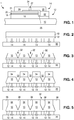
- Fig. 1 illustrates a III-nitride LED that may be used in example embodiments of the device. Any suitable semiconductor light emitting device may be used and embodiments of the invention are not limited to the device illustrated in Fig. 1 .
- the device of Fig. 1 is formed by growing a III-nitride semiconductor structure 12 on a growth substrate 10 as is known in the art.
- the growth substrate is often sapphire but may be any suitable substrate such as, for example, SiC, Si, GaN, or a composite substrate.
- a surface of the growth substrate on which the III-nitride semiconductor structure is grown may be patterned, roughened, or textured before growth, which may improve light extraction from the device.
- a surface of the growth substrate opposite the growth surface i.e. the surface through which a majority of light is extracted in a flip chip configuration
- the semiconductor structure includes a light emitting or active region sandwiched between n- and p-type regions.
- An n-type region 16 may be grown first and may include multiple layers of different compositions and dopant concentration including, for example, preparation layers such as buffer layers or nucleation layers, which may be n-type or not intentionally doped, and n- or even p-type device layers designed for particular optical, material, or electrical properties desirable for the light emitting region to efficiently emit light.
- a light emitting or active region 18 is grown over the n-type region. Examples of suitable light emitting regions include a single thick or thin light emitting layer, or a multiple quantum well light emitting region including multiple thin or thick light emitting layers separated by barrier layers.
- a p-type region 20 may then be grown over the light emitting region.
- the p-type region may include multiple layers of different composition, thickness, and dopant concentration, including layers that are not intentionally doped, or n-type layers.
- a p-contact is formed on the surface of the p-type region.
- the p-contact 21 often includes multiple conductive layers such as a reflective metal and a guard metal which may prevent or reduce electromigration of the reflective metal.
- the reflective metal is often silver but any suitable material or materials may be used.
- a portion of the p-contact 21, the p-type region 20, and the active region 18 is removed to expose a portion of the n-type region 16 on which an n-contact 22 is formed.
- the n- and p-contacts 22 and 21 are electrically isolated from each other by a gap 25 which may be filled with a dielectric such as an oxide of silicon or any other suitable material.
- n-contact vias may be formed; the n- and p-contacts 22 and 21 are not limited to the arrangement illustrated in Fig. 1 .
- the n- and p-contacts may be redistributed to form bond pads with a dielectric/metal stack, as is known in the art.
- one or more interconnects 26 and 28 are formed on or electrically connected to the n- and p-contacts 22 and 21.
- Interconnect 26 is electrically connected to n-contact 22 in Fig. 1 .
- Interconnect 28 is electrically connected to p-contact 21.
- Interconnects 26 and 28 are electrically isolated from the n- and p-contacts 22 and 21 and from each other by dielectric layer 24 and gap 27.
- Interconnects 26 and 28 may be, for example, solder, stud bumps, gold layers, or any other suitable structure.
- Many individual LEDs are formed on a single wafer then diced from the wafer of devices.
- the semiconductor structure and the n- and p-contacts 22 and 21 of a wafer of LEDs are represented in the following figures by block 12.
- the interconnects 26 and 28 of a wafer of LEDs are represented by block 14.
- the substrate 10 may be thinned after growth of the semiconductor structure or after forming the individual devices as described above in reference to Fig. 1 . After thinning, the substrate may be at least 50 ⁇ m thick in some embodiments, no more than 150 ⁇ m thick in some embodiments, at least 80 ⁇ m thick in some embodiments and no more than 120 ⁇ m thick in some embodiments.
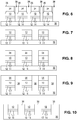
- Figs. 2, 3, 4, 5 , and 6 illustrate forming a device according to embodiments of the invention.
- Temporary carrier 30 may be any suitable material such as, for example, wafer handling tape.
- slots 32 are formed in the growth substrate 10. Slots 32 are no more than 50 ⁇ m wide (for example, at the top of a slot with an angled sidewall as illustrated in Fig. 3 ) in some embodiments. The slots are disposed in the region between LEDs where the structure will be cut, as described below, to separate the wafer into individual LEDs or groups of LEDs.
- the slots may be formed by any suitable technique including, for example, wet or dry etching, laser scribing, or mechanical cutting such as sawing with a diamond blade.
- the slots 32 may extend through the entire thickness of substrate 10, though they need not.
- the slots 32 may have angled sidewalls, as illustrated in Fig. 3 , though angled sidewalls are not required.
- wavelength converting members 34 are attached to the top of substrate 10, such that the wavelength converting members are aligned with individual LEDs or groups of LEDs.
- Wavelength converting members 34 are generally wavelength converting structures that are formed separately from the wafer of LEDs, then attached to the substrate 10. As such, wavelength converting members 34 are self-supporting structures, not structures that are formed in situ on the substrate 10. Examples of suitable wavelength converting members 34 include phosphor that is formed into ceramic platelets, for example by sintering, and/or a phosphor or other wavelength converting material disposed in a transparent material, such as glass, silicone, or epoxy, that is cast or otherwise formed into a sheet, then cut into individual wavelength converting members 34.
- the wavelength converting material in wavelength converting members 34 may be, for example, conventional phosphors, organic phosphors, quantum dots, organic semiconductors, II-VI or III-V semiconductors, II-VI or III-V semiconductor quantum dots or nanocrystals, dyes, polymers, or other materials that luminesce.
- the wavelength converting material absorbs light emitted by the LED and emits light of one or more different wavelengths. Unconverted light emitted by the LED is often part of the final spectrum of light extracted from the structure, though it need not be.
- Examples of common combinations include a blue-emitting LED combined with a yellow-emitting wavelength converting material, a blue-emitting LED combined with green- and red-emitting wavelength converting materials, a UV-emitting LED combined with blue- and yellow-emitting wavelength converting materials, and a UV-emitting LED combined with blue-, green-, and red-emitting wavelength converting materials.
- Wavelength converting materials emitting other colors of light may be added to tailor the spectrum of light emitted from the structure.
- Wavelength converting member 34 may be attached to substrate 10 by, for example, gluing with a material such as silicone or any other suitable adhesive, direct bonding, or any other suitable technique.
- a reflective material 36 is disposed in the slots 32 formed in Fig. 3 .
- Reflective material may be, for example, reflective or other particles disposed in a transparent material.
- the particles and transparent material may be selected to have substantially different indices of refraction in order to cause optical scattering.
- the transparent material has a low index (for example, silicone may have an index of refraction of 1.4 or less) and the particles have a higher index (for example, TiO 2 has an index of refraction of 2.6).
- Any suitable reflective particle may be used, including, for example, TiO 2 , ZnO, or Al 2 O 3 .
- suitable transparent materials include silicone molding compound, liquid silicone, epoxy, and glass.
- the reflective particles, the transparent material, and/or the combination of reflective particles and transparent material has a higher thermal conductivity than common silicone materials. Common silicone materials typically have a thermal conductivity around 0.1-0.2W/mK.
- Reflective material 36 may be disposed in the slots 32 by any suitable technique such as, for example, dispensing or molding. Reflective material 36 may completely fill slots 32, as illustrated in Fig. 5 , such that the top of the reflective material 36 is coplanar with the tops of wavelength converting members 34 in some embodiments. Reflective material 36 does not completely fill slots 32 in some embodiments. In some embodiments, excessive reflective material 36 is removed after disposing the reflective material 36 in the slots. For example, reflective material that extends above the tops of slots 32, or that covers the LEDs, may be removed by any suitable technique, such as mechanical abrasion, grinding, or microbead blasting.
- individual LEDs are separated from the wafer by cutting through the reflective material 36 and the LED wafer in the regions 38 between LEDs.
- Individual LEDs may be cut from the wafer by any suitable technique including, for example, diamond sawing, laser cutting, or scribing and breaking.
- the kerf formed by cutting may be, for example, no more than 20 ⁇ m wide.
- the necessary thickness of reflective material 36 remaining on the sides of the LEDs in Fig. 6 after cutting, for proper functioning of the reflective material may depend on the type of reflective material. For reflective metal films, no more than 1 ⁇ m is required in some embodiments.
- diffuse reflectors such as TiO 2 in silicone, the reflectivity may depend on the thickness. For example, a diffuse reflector that is at least 90% reflective may be 20 ⁇ m thick or less in some embodiments and a diffuse reflector that is at least 95% reflective may be 50 ⁇ m thick or less in some embodiments.
- the finished LEDs are removed from the temporary carrier 30 by any suitable technique such as, for example, thermal release, transfer to a different carrier, or direct picking.
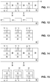
- Figs. 7, 8, and 9 illustrate an alternative embodiment, where individual LEDs are first separated from a wafer, then rearranged with larger pitch on a temporary carrier.
- a carrier 30 which may be a temporary carrier such as those described above in reference to Fig. 2 .
- the LEDs may be spaced at least 100 ⁇ m apart in some embodiments, no more than 800 ⁇ m apart in some embodiments, at least 400 ⁇ m apart in some embodiments, and no more than 600 ⁇ m apart in some embodiments.
- the growth substrate 10 on each LED may have substantially vertical sidewalls, rather than the angled sidewalls illustrated in the embodiment described in Figs. 2-6 , though vertical sidewalls are not required and the shape of the sidewall may depend on the technique used to separate the LEDs.
- wavelength converting elements 34 are attached to the growth substrate 10 of each LED, as described above in reference to Fig. 4 .
- reflective material 36 is disposed in the gaps between the LEDs, as described above in reference to Fig. 5 .
- the individual devices may be separated by cutting the reflective material, as described above in reference to Fig. 6 , then removed from the temporary carrier, as described above in reference to Fig. 6 .
- Figs. 10 and 11 illustrate an alternative embodiment where individual LEDs are first separated from a growth wafer, then disposed on a temporary carrier.
- individual LEDs are placed on a carrier 30 (as illustrated in Fig. 7 ), which may be a temporary carrier such as those described above in reference to Fig. 2 .
- Reflective material 36 is disposed in the regions between the LEDs, as described above in reference to Fig. 5 .
- a wavelength converting layer 40 is formed over the LEDs and the reflective material 36.
- Wavelength converting layer 40 may be, for example, a phosphor disposed in a transparent material such as silicone.
- Wavelength converting layer 40 may be formed by any suitable technique including, for example, lamination, molding, dispensing, spray coating, or spin coating.
- the LEDs are then separated by cutting through the structure, for example in regions 38 between neighboring LEDs, as described above in reference to Fig. 6 .
- the LEDs are then removed from the temporary carrier 30, as described above in reference to Fig. 6 .
- Figs. 12, 13, and 14 illustrate an alternative embodiment.
- individual wavelength converting elements 34 are placed on a carrier 30, which may be a temporary carrier such as those described above in reference to Fig. 2 .
- the wavelength converting elements 34 are described above in reference to Fig. 4 .
- LEDs are attached to the wavelength converting elements 34.
- the LEDs may be attached using the methods and materials described above in reference to Fig 4 .
- a reflective material 36 is disposed in the regions between the LEDs, as described above in reference to Fig. 5 .
- the LEDs are then separated by cutting through the structure, for example in regions 38 between neighboring LEDs, as described above in reference to Fig. 6 .
- the LEDs are then removed from the temporary carrier 30, as described above in reference to Fig. 6 .
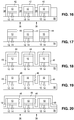
- Figs. 15 and 16 illustrate an alternative embodiment.
- LEDs are attached to a temporary carrier 30, which may be a temporary carrier such as those described above in reference to Fig. 2 .
- a temporary carrier such as those described above in reference to Fig. 2 .
- the tops of the LEDs in some embodiments, and the tops and sides of the LEDs in some embodiments are covered with a wavelength converting layer 42.
- the wavelength converting layer 42 may be, for example, a wavelength converting material mixed with a transparent material, and may be formed by any suitable technique, including, for example, lamination, molding, or electrophoretic deposition.
- a reflective material 36 is disposed in the regions between the LEDs, as described above in reference to Fig. 5 .
- the reflective material 36 may be formed by a technique that limits damage to the substantially conformal wavelength converting layer 42.
- One example of a suitable technique is dispensing reflective particles mixed with liquid silicone in the areas between the LEDs, then curing the liquid silicone.
- the LEDs are then separated by cutting through the structure, for example in regions 38 between neighboring LEDs, as described above in reference to Fig. 6 .
- the LEDs are then removed from the temporary carrier 30, as described above in reference to Fig. 6 .
- Figs. 17, 18, 19, and 20 illustrate an alternative embodiment.
- LEDs are attached to a temporary carrier 30, which may be a temporary carrier such as those described above in reference to Fig. 2 .
- a temporary carrier such as those described above in reference to Fig. 2 .
- the tops of the LEDs are covered with a masking layer 44.
- the masking layer is applied to the growth substrate of a wafer of LEDs, before singulating the LEDs by cutting the growth substrate.
- the masking layer 44 may be, for example, photoresist, dielectric material, or any other suitable material.
- Masking layer 44 may be formed by any suitable technique, including, for example, spin-coating, roller-coating, dip-coating, lamination, spray-coating, evaporation, sputtering, and direct pick and place of a piece part such as a piece of glass.
- the masking layer 44 is patterned, for example, by photolithography, shadow masking, and/or wet or dry chemical etching.
- a reflective coating 46 is disposed over the structure illustrated in Fig. 17 .
- the reflective coating 46 may be any suitable material including, for example, a dichroic mirror, a distributed Bragg reflector (DBR), metallic film, or other suitable dielectric stack.
- the reflective coating 46 may be formed by any suitable technique including, for example, physical vapor deposition, CVD, sputtering, evaporation, and spray-coating.
- the reflective coating 46 may substantially conformally coat the structure, as illustrated in Fig. 18 , though this is not required.
- the masking layer 44 and the reflective coating 46 over the tops of the LEDs are removed by any suitable process such as, for example, a lift-off process. After removing the masking layer 44, reflective coating 46 remains on the sidewalls of the LEDs and the regions between the LEDs.
- Wavelength converting layer 48 is formed over the structure illustrated in Fig. 19 .
- Wavelength converting layer 48 may be, for example, a wavelength converting material mixed with a transparent material, and may be formed by any suitable technique including, for example, lamination, molding, spray coating, or spin coating.
- Wavelength converting layer 48 may fill the regions between the LEDs, as illustrated in Fig. 20 , or wavelength converting layer 48 may be a substantially conformal layer.
- the LEDs are then separated by cutting through the structure, for example in regions 38 between neighboring LEDs, as described above in reference to Fig. 6 .
- the LEDs are then removed from the temporary carrier 30, as described above in reference to Fig. 6 .
- a lens or other optical element is formed over the finished LED, which may be any of the devices described above.
- the sidewalls of the growth substrate may be angled.
Description
- The present invention relates to the fabrication of top-emitting, wavelength-converted semiconductor light emitting devices.
- Semiconductor light-emitting devices including light emitting diodes (LEDs), resonant cavity light emitting diodes (RCLEDs), vertical cavity laser diodes (VCSELs), and edge emitting lasers are among the most efficient light sources currently available. Materials systems currently of interest in the manufacture of high-brightness light emitting devices capable of operation across the visible spectrum include Group III-V semiconductors, particularly binary, ternary, and quaternary alloys of gallium, aluminum, indium, and nitrogen, also referred to as III-nitride materials. Typically, III-nitride light emitting devices are fabricated by epitaxially growing a stack of semiconductor layers of different compositions and dopant concentrations on a sapphire, silicon carbide, III-nitride, or other suitable substrate by metal-organic chemical vapor deposition (MOCVD), molecular beam epitaxy (MBE), or other epitaxial techniques. The stack often includes one or more n-type layers doped with, for example, Si, formed over the substrate, one or more light emitting layers in an active region formed over the n-type layer or layers, and one or more p-type layers doped with, for example, Mg, formed over the active region. Electrical contacts are formed on the n- and p-type regions.
- LEDs that emit light only from a surface that is commonly referred to as the "top" surface (i.e. devices where light emission from the side surfaces of the LED is substantially reduced or eliminated) are often formed by growing an LED semiconductor structure on a growth substrate, attaching the semiconductor structure to a mount, then removing the growth substrate.
-
US 2011/0198665 A1 discloses a method for manufacturing a light emitting element from a stacked body on a surface of a translucent substrate. Trenches are provided in the stacked body into the substrate and filled with a resin. A support plate is provided before grinding the substrate up to the trenches. -
US 2010/0279437 A1 discloses a method for wafer scale fabrication of light emitting diodes. The method comprises separating LED dies to create spaces between the LED dies and filling the spaces with a reflective coating, which reflective coating will remain on the lateral sides of LED dies. - It is an object of the invention to provide an improved method for obtaining a device that emits a majority of light from the top surface of the device, without requiring removal of the growth substrate.
- Example embodiments of the device include a semiconductor structure including a light emitting layer sandwiched between an n-type region and a p-type region. A growth substrate is attached to the semiconductor structure. The growth substrate has at least one angled sidewall. A reflective layer is disposed on the angled sidewall. A majority of light extracted from the semiconductor structure and the growth substrate is extracted through a top surface of the growth substrate.
- Example embodiments of the device include a semiconductor structure including a light emitting layer sandwiched between an n-type region and a p-type region. A growth substrate having a thickness less than 150 microns is attached to the semiconductor structure. A reflective layer is disposed on a sidewall of the growth substrate and a sidewall of the semiconductor structure. A majority of light extracted from the semiconductor structure and the growth substrate is extracted through a top surface of the growth substrate.
- The method according to the invention is defined in the claims.
- This disclosure contains embodiments from which some are embodiments of the invention.
-
-
Fig. 1 illustrates one example of a III-nitride LED. -
Fig. 2 illustrates a wafer of LEDs attached to a temporary carrier. -
Fig. 3 illustrates the structure ofFig. 2 after forming slots in the growth substrate. -
Fig. 4 illustrates the structure ofFig. 3 after attaching wavelength converting members to the LEDs. -
Fig. 5 illustrates the structure ofFig. 4 after filling the areas between the LEDs with reflective material. -
Fig. 6 illustrates the structure ofFig. 5 after separating the LEDs. -
Fig. 7 illustrates LEDs attached to a temporary carrier. -
Fig. 8 illustrates the structure ofFig. 7 after attaching wavelength converting members to the LEDs. -
Fig. 9 illustrates the structure ofFig. 8 after filling the areas between the LEDs with reflective material. -
Fig. 10 illustrates the structure ofFig. 7 after filling the areas between the LEDs with reflective material. -
Fig. 11 illustrates the structure ofFig. 10 after forming a wavelength converting layer over the LEDs. -
Fig. 12 illustrates wavelength converting members attached to a temporary carrier. -
Fig. 13 illustrates the structure ofFig. 12 after attaching LEDs to the wavelength converting members. -
Fig. 14 illustrates the structure ofFig. 13 after filling the areas between the LEDs with reflective material. -
Fig. 15 illustrates LEDs with a substantially conformal wavelength converting layer attached to a temporary carrier. -
Fig. 16 illustrates the structure ofFig. 15 after filling the areas between the LEDs with reflective material. -
Fig. 17 illustrates LEDs with a mask layer formed over the tops of the LEDs attached to a temporary carrier. -
Fig. 18 illustrates the structure ofFig. 17 after forming a reflective layer. -
Fig. 19 illustrates the structure ofFig. 18 after removing the mask layer. -
Fig. 20 illustrates the structure ofFig. 19 after forming a wavelength converting layer over the structure. - In example embodiments of the device, wafers of semiconductor LEDs grown on a growth substrate are processed into individual devices or groups of devices where a majority of light is extracted through a top surface of each LED. A reflective material is disposed on the sides of the device to prevent light from escaping from the sides of the device, or to reduce the amount of light extracted from the sides of the device. The reflective material may also increase the amount of light extracted through the top surface of the LED.
- Though in the examples below the semiconductor light emitting devices are III-nitride LEDs that emit blue or UV light, semiconductor light emitting devices besides LEDs such as laser diodes and semiconductor light emitting devices made from other materials systems such as other III-V materials, III-phosphide, III-arsenide, II-VI materials, ZnO, or Si-based materials may be used.
-
Fig. 1 illustrates a III-nitride LED that may be used in example embodiments of the device. Any suitable semiconductor light emitting device may be used and embodiments of the invention are not limited to the device illustrated inFig. 1 . The device ofFig. 1 is formed by growing a III-nitride semiconductor structure 12 on agrowth substrate 10 as is known in the art. The growth substrate is often sapphire but may be any suitable substrate such as, for example, SiC, Si, GaN, or a composite substrate. A surface of the growth substrate on which the III-nitride semiconductor structure is grown may be patterned, roughened, or textured before growth, which may improve light extraction from the device. A surface of the growth substrate opposite the growth surface (i.e. the surface through which a majority of light is extracted in a flip chip configuration) may be patterned, roughened or textured before or after growth, which may improve light extraction from the device. - The semiconductor structure includes a light emitting or active region sandwiched between n- and p-type regions. An n-
type region 16 may be grown first and may include multiple layers of different compositions and dopant concentration including, for example, preparation layers such as buffer layers or nucleation layers, which may be n-type or not intentionally doped, and n- or even p-type device layers designed for particular optical, material, or electrical properties desirable for the light emitting region to efficiently emit light. A light emitting oractive region 18 is grown over the n-type region. Examples of suitable light emitting regions include a single thick or thin light emitting layer, or a multiple quantum well light emitting region including multiple thin or thick light emitting layers separated by barrier layers. A p-type region 20 may then be grown over the light emitting region. Like the n-type region, the p-type region may include multiple layers of different composition, thickness, and dopant concentration, including layers that are not intentionally doped, or n-type layers. - After growth, a p-contact is formed on the surface of the p-type region. The p-
contact 21 often includes multiple conductive layers such as a reflective metal and a guard metal which may prevent or reduce electromigration of the reflective metal. The reflective metal is often silver but any suitable material or materials may be used. After forming the p-contact 21, a portion of the p-contact 21, the p-type region 20, and theactive region 18 is removed to expose a portion of the n-type region 16 on which an n-contact 22 is formed. The n- and p-contacts gap 25 which may be filled with a dielectric such as an oxide of silicon or any other suitable material. Multiple n-contact vias may be formed; the n- and p-contacts Fig. 1 . The n- and p-contacts may be redistributed to form bond pads with a dielectric/metal stack, as is known in the art. - In order to form electrical connections to the LED, one or
more interconnects contacts Interconnect 26 is electrically connected to n-contact 22 inFig. 1 .Interconnect 28 is electrically connected to p-contact 21.Interconnects contacts dielectric layer 24 andgap 27.Interconnects contacts block 12. Theinterconnects block 14. - The
substrate 10 may be thinned after growth of the semiconductor structure or after forming the individual devices as described above in reference toFig. 1 . After thinning, the substrate may be at least 50 µm thick in some embodiments, no more than 150 µm thick in some embodiments, at least 80 µm thick in some embodiments and no more than 120 µm thick in some embodiments. -
Figs. 2, 3, 4, 5 , and6 illustrate forming a device according to embodiments of the invention. - In
Fig. 2 , before the wafer of LEDs is diced into individual LEDs or groups of LEDs, the wafer is attached to atemporary carrier 30 through theinterconnects 14. Thetemporary carrier 30 stabilizes the wafer for the following processing steps.Temporary carrier 30 may be any suitable material such as, for example, wafer handling tape. - In
Fig. 3 ,slots 32 are formed in thegrowth substrate 10.Slots 32 are no more than 50 µm wide (for example, at the top of a slot with an angled sidewall as illustrated inFig. 3 ) in some embodiments. The slots are disposed in the region between LEDs where the structure will be cut, as described below, to separate the wafer into individual LEDs or groups of LEDs. The slots may be formed by any suitable technique including, for example, wet or dry etching, laser scribing, or mechanical cutting such as sawing with a diamond blade. Theslots 32 may extend through the entire thickness ofsubstrate 10, though they need not. Theslots 32 may have angled sidewalls, as illustrated inFig. 3 , though angled sidewalls are not required. - In
Fig. 4 ,wavelength converting members 34 are attached to the top ofsubstrate 10, such that the wavelength converting members are aligned with individual LEDs or groups of LEDs.Wavelength converting members 34 are generally wavelength converting structures that are formed separately from the wafer of LEDs, then attached to thesubstrate 10. As such,wavelength converting members 34 are self-supporting structures, not structures that are formed in situ on thesubstrate 10. Examples of suitablewavelength converting members 34 include phosphor that is formed into ceramic platelets, for example by sintering, and/or a phosphor or other wavelength converting material disposed in a transparent material, such as glass, silicone, or epoxy, that is cast or otherwise formed into a sheet, then cut into individualwavelength converting members 34. - The wavelength converting material in
wavelength converting members 34 may be, for example, conventional phosphors, organic phosphors, quantum dots, organic semiconductors, II-VI or III-V semiconductors, II-VI or III-V semiconductor quantum dots or nanocrystals, dyes, polymers, or other materials that luminesce. The wavelength converting material absorbs light emitted by the LED and emits light of one or more different wavelengths. Unconverted light emitted by the LED is often part of the final spectrum of light extracted from the structure, though it need not be. Examples of common combinations include a blue-emitting LED combined with a yellow-emitting wavelength converting material, a blue-emitting LED combined with green- and red-emitting wavelength converting materials, a UV-emitting LED combined with blue- and yellow-emitting wavelength converting materials, and a UV-emitting LED combined with blue-, green-, and red-emitting wavelength converting materials. Wavelength converting materials emitting other colors of light may be added to tailor the spectrum of light emitted from the structure. -
Wavelength converting member 34 may be attached tosubstrate 10 by, for example, gluing with a material such as silicone or any other suitable adhesive, direct bonding, or any other suitable technique. - In
Fig. 5 , areflective material 36 is disposed in theslots 32 formed inFig. 3 . Reflective material may be, for example, reflective or other particles disposed in a transparent material. The particles and transparent material may be selected to have substantially different indices of refraction in order to cause optical scattering. In some embodiments, the transparent material has a low index (for example, silicone may have an index of refraction of 1.4 or less) and the particles have a higher index (for example, TiO2 has an index of refraction of 2.6). Any suitable reflective particle may be used, including, for example, TiO2, ZnO, or Al2O3. Examples of suitable transparent materials include silicone molding compound, liquid silicone, epoxy, and glass. In some embodiments, the reflective particles, the transparent material, and/or the combination of reflective particles and transparent material has a higher thermal conductivity than common silicone materials. Common silicone materials typically have a thermal conductivity around 0.1-0.2W/mK. -
Reflective material 36 may be disposed in theslots 32 by any suitable technique such as, for example, dispensing or molding.Reflective material 36 may completely fillslots 32, as illustrated inFig. 5 , such that the top of thereflective material 36 is coplanar with the tops ofwavelength converting members 34 in some embodiments.Reflective material 36 does not completely fillslots 32 in some embodiments. In some embodiments, excessivereflective material 36 is removed after disposing thereflective material 36 in the slots. For example, reflective material that extends above the tops ofslots 32, or that covers the LEDs, may be removed by any suitable technique, such as mechanical abrasion, grinding, or microbead blasting. - In
Fig. 6 , individual LEDs are separated from the wafer by cutting through thereflective material 36 and the LED wafer in theregions 38 between LEDs. Individual LEDs may be cut from the wafer by any suitable technique including, for example, diamond sawing, laser cutting, or scribing and breaking. The kerf formed by cutting may be, for example, no more than 20 µm wide. The necessary thickness ofreflective material 36 remaining on the sides of the LEDs inFig. 6 after cutting, for proper functioning of the reflective material, may depend on the type of reflective material. For reflective metal films, no more than 1 µm is required in some embodiments. For diffuse reflectors such as TiO2 in silicone, the reflectivity may depend on the thickness. For example, a diffuse reflector that is at least 90% reflective may be 20 µm thick or less in some embodiments and a diffuse reflector that is at least 95% reflective may be 50 µm thick or less in some embodiments. - After cutting, the finished LEDs are removed from the
temporary carrier 30 by any suitable technique such as, for example, thermal release, transfer to a different carrier, or direct picking. - One disadvantage of the method and resulting device illustrated in
Figs. 2-6 is that the available area forwavelength converting member 34 andreflective material 36 is limited by the original pitch of the LEDs on thegrowth substrate wafer 10. The area between neighboring LEDs is limited, for example for cost reasons, which limits the size ofwavelength converting member 34 and the thickness ofreflective material 36.Figs. 7, 8, and 9 illustrate an alternative embodiment, where individual LEDs are first separated from a wafer, then rearranged with larger pitch on a temporary carrier. - In
Fig. 7 , individual LEDs are placed on acarrier 30, which may be a temporary carrier such as those described above in reference toFig. 2 . The LEDs may be spaced at least 100 µm apart in some embodiments, no more than 800 µm apart in some embodiments, at least 400 µm apart in some embodiments, and no more than 600 µm apart in some embodiments. Thegrowth substrate 10 on each LED may have substantially vertical sidewalls, rather than the angled sidewalls illustrated in the embodiment described inFigs. 2-6 , though vertical sidewalls are not required and the shape of the sidewall may depend on the technique used to separate the LEDs. - In
Fig. 8 ,wavelength converting elements 34 are attached to thegrowth substrate 10 of each LED, as described above in reference toFig. 4 . - In
Fig. 9 ,reflective material 36 is disposed in the gaps between the LEDs, as described above in reference toFig. 5 . The individual devices may be separated by cutting the reflective material, as described above in reference toFig. 6 , then removed from the temporary carrier, as described above in reference toFig. 6 . -
Figs. 10 and11 illustrate an alternative embodiment where individual LEDs are first separated from a growth wafer, then disposed on a temporary carrier. InFig. 10 , individual LEDs are placed on a carrier 30 (as illustrated inFig. 7 ), which may be a temporary carrier such as those described above in reference toFig. 2 .Reflective material 36 is disposed in the regions between the LEDs, as described above in reference toFig. 5 . - In
Fig. 11 , awavelength converting layer 40 is formed over the LEDs and thereflective material 36.Wavelength converting layer 40 may be, for example, a phosphor disposed in a transparent material such as silicone.Wavelength converting layer 40 may be formed by any suitable technique including, for example, lamination, molding, dispensing, spray coating, or spin coating. The LEDs are then separated by cutting through the structure, for example inregions 38 between neighboring LEDs, as described above in reference toFig. 6 . The LEDs are then removed from thetemporary carrier 30, as described above in reference toFig. 6 . -
Figs. 12, 13, and 14 illustrate an alternative embodiment. InFig. 12 , individualwavelength converting elements 34 are placed on acarrier 30, which may be a temporary carrier such as those described above in reference toFig. 2 . Thewavelength converting elements 34 are described above in reference toFig. 4 . - In
Fig. 13 , LEDs are attached to thewavelength converting elements 34. The LEDs may be attached using the methods and materials described above in reference toFig 4 . - In
Fig. 14 , areflective material 36 is disposed in the regions between the LEDs, as described above in reference toFig. 5 . The LEDs are then separated by cutting through the structure, for example inregions 38 between neighboring LEDs, as described above in reference toFig. 6 . The LEDs are then removed from thetemporary carrier 30, as described above in reference toFig. 6 . -
Figs. 15 and16 illustrate an alternative embodiment. InFig. 15 , LEDs are attached to atemporary carrier 30, which may be a temporary carrier such as those described above in reference toFig. 2 . Before or after attaching the LEDs to thetemporary carrier 30, the tops of the LEDs in some embodiments, and the tops and sides of the LEDs in some embodiments, are covered with awavelength converting layer 42. Thewavelength converting layer 42 may be, for example, a wavelength converting material mixed with a transparent material, and may be formed by any suitable technique, including, for example, lamination, molding, or electrophoretic deposition. - In
Fig. 16 , areflective material 36 is disposed in the regions between the LEDs, as described above in reference toFig. 5 . Thereflective material 36 may be formed by a technique that limits damage to the substantially conformalwavelength converting layer 42. One example of a suitable technique is dispensing reflective particles mixed with liquid silicone in the areas between the LEDs, then curing the liquid silicone. The LEDs are then separated by cutting through the structure, for example inregions 38 between neighboring LEDs, as described above in reference toFig. 6 . The LEDs are then removed from thetemporary carrier 30, as described above in reference toFig. 6 . -
Figs. 17, 18, 19, and 20 illustrate an alternative embodiment. InFig. 17 , LEDs are attached to atemporary carrier 30, which may be a temporary carrier such as those described above in reference toFig. 2 . Before or after attaching the LEDs to the temporary carrier, the tops of the LEDs are covered with amasking layer 44. In some embodiments, the masking layer is applied to the growth substrate of a wafer of LEDs, before singulating the LEDs by cutting the growth substrate. Themasking layer 44 may be, for example, photoresist, dielectric material, or any other suitable material. Maskinglayer 44 may be formed by any suitable technique, including, for example, spin-coating, roller-coating, dip-coating, lamination, spray-coating, evaporation, sputtering, and direct pick and place of a piece part such as a piece of glass. In some embodiments, themasking layer 44 is patterned, for example, by photolithography, shadow masking, and/or wet or dry chemical etching. - In
Fig. 18 , areflective coating 46 is disposed over the structure illustrated inFig. 17 . Thereflective coating 46 may be any suitable material including, for example, a dichroic mirror, a distributed Bragg reflector (DBR), metallic film, or other suitable dielectric stack. Thereflective coating 46 may be formed by any suitable technique including, for example, physical vapor deposition, CVD, sputtering, evaporation, and spray-coating. Thereflective coating 46 may substantially conformally coat the structure, as illustrated inFig. 18 , though this is not required. - In
Fig. 19 , themasking layer 44 and thereflective coating 46 over the tops of the LEDs are removed by any suitable process such as, for example, a lift-off process. After removing themasking layer 44,reflective coating 46 remains on the sidewalls of the LEDs and the regions between the LEDs. - In
Fig. 20 , awavelength converting layer 48 is formed over the structure illustrated inFig. 19 .Wavelength converting layer 48 may be, for example, a wavelength converting material mixed with a transparent material, and may be formed by any suitable technique including, for example, lamination, molding, spray coating, or spin coating.Wavelength converting layer 48 may fill the regions between the LEDs, as illustrated inFig. 20 , orwavelength converting layer 48 may be a substantially conformal layer. The LEDs are then separated by cutting through the structure, for example inregions 38 between neighboring LEDs, as described above in reference toFig. 6 . The LEDs are then removed from thetemporary carrier 30, as described above in reference toFig. 6 . - In some embodiments, a lens or other optical element is formed over the finished LED, which may be any of the devices described above. In any of the devices described above, in some embodiments, the sidewalls of the growth substrate may be angled.
- Having described the invention in detail, those skilled in the art will appreciate that, given the present disclosure, modifications may be made to the invention without departing from the scope of the invention defined by the appended claims. Therefore, it is not intended that the scope of the invention be limited to the specific embodiments illustrated and described.
Claims (3)
- A method comprising:growing a semiconductor structure (16, 18, 20) on a growth substrate (10);forming interconnects (14) on the semiconductor structure (12) grown on the growth substrate (10) for a wafer of a plurality of semiconductor light emitting devices;attaching the interconnects (14) of the wafer of a plurality of semiconductor light emitting devices to a carrier (30);removing areas (32) of the wafer of semiconductor light emitting devices between the semiconductor light emitting devicesdisposing a material (36) in the areas between the semiconductor light emitting devices; andseparating two neighboring semiconductor light emitting devices, wherein separating comprises cutting the material;characterized by,removing the areas between the semiconductor light emitting devices while the wafer of semiconductor light emitting devices is attached to the carrier; andremoving the carrier after separating two neighboring semiconductor light emitting devices;wherein the material disposed in the areas between the semiconductor light emitting devices is reflective.
- The method of claim 1 wherein removing areas (32) of the wafer of semiconductor light emitting devices between the semiconductor light emitting devices comprises forming slots in the growth substrate wafer in areas between the semiconductor light emitting devices, wherein disposing a reflective material in areas between the semiconductor light emitting devices comprises disposing a reflective material in the slots.
- The method of claim 1 further comprising attaching a wavelength converting member to each of the semiconductor light emitting devices of the wafer of a plurality of semiconductor light emitting devices prior to disposing a reflective material in areas between the semiconductor light emitting devices, wherein the wavelength converting member is formed separately from the semiconductor light emitting device.
Applications Claiming Priority (3)
| Application Number | Priority Date | Filing Date | Title |
|---|---|---|---|
| US201361810833P | 2013-04-11 | 2013-04-11 | |
| US201361900466P | 2013-11-06 | 2013-11-06 | |
| PCT/IB2014/060310 WO2014167455A2 (en) | 2013-04-11 | 2014-03-31 | Top emitting semiconductor light emitting device |
Publications (2)
| Publication Number | Publication Date |
|---|---|
| EP2984685A2 EP2984685A2 (en) | 2016-02-17 |
| EP2984685B1 true EP2984685B1 (en) | 2018-12-19 |
Family
ID=51690078
Family Applications (1)
| Application Number | Title | Priority Date | Filing Date |
|---|---|---|---|
| EP14716970.0A Active EP2984685B1 (en) | 2013-04-11 | 2014-03-31 | Fabrication method for top emitting semiconductor light emitting devices |
Country Status (7)
| Country | Link |
|---|---|
| US (1) | US9871167B2 (en) |
| EP (1) | EP2984685B1 (en) |
| JP (2) | JP6680670B2 (en) |
| KR (1) | KR102245056B1 (en) |
| CN (3) | CN105378950A (en) |
| TW (1) | TWI659551B (en) |
| WO (1) | WO2014167455A2 (en) |
Families Citing this family (25)
| Publication number | Priority date | Publication date | Assignee | Title |
|---|---|---|---|---|
| KR102180388B1 (en) * | 2013-07-08 | 2020-11-19 | 루미리즈 홀딩 비.브이. | Wavelength converted semiconductor light emitting device |
| CN104716245A (en) | 2013-12-13 | 2015-06-17 | 晶元光电股份有限公司 | Light emitting device and manufacturing method thereof |
| DE102014101492A1 (en) * | 2014-02-06 | 2015-08-06 | Osram Opto Semiconductors Gmbh | Optoelectronic semiconductor component |
| US20160225962A1 (en) * | 2015-01-30 | 2016-08-04 | Empire Technology Development Llc | Nanoparticle gradient refractive index encapsulants for semi-conductor diodes |
| US10121770B2 (en) * | 2015-02-18 | 2018-11-06 | Koninklijke Philips N.V. | Device with multiple, stacked light emitting devices |
| DE102015107593A1 (en) * | 2015-05-13 | 2016-11-17 | Osram Opto Semiconductors Gmbh | Optoelectronic semiconductor chip and illuminant |
| JP7181792B2 (en) * | 2015-08-03 | 2022-12-01 | ルミレッズ ホールディング ベーフェー | Semiconductor light emitting device with reflective side coating |
| US9753277B2 (en) | 2015-08-11 | 2017-09-05 | Delta Electronics, Inc. | Wavelength conversion device |
| JP6327220B2 (en) * | 2015-08-31 | 2018-05-23 | 日亜化学工業株式会社 | Light emitting device |
| WO2017052800A1 (en) * | 2015-09-25 | 2017-03-30 | Koninklijke Philips N.V. | Surface emitter with light-emitting area equal to the led top surface and its fabrication |
| TWI587543B (en) * | 2015-12-15 | 2017-06-11 | 李乃義 | Light emitting diode packaging structure and method for manufacturing the same |
| JP6974324B2 (en) * | 2015-12-29 | 2021-12-01 | ルミレッズ ホールディング ベーフェー | Flip chip LED with side reflector and phosphor |
| KR20180100157A (en) | 2015-12-29 | 2018-09-07 | 루미리즈 홀딩 비.브이. | Flip Chip LEDs with Side Reflectors and Phosphors |
| FR3056014B1 (en) * | 2016-09-15 | 2020-05-29 | Valeo Vision | METHOD FOR CREATING OPTICAL ISOLATION BETWEEN PIXELS OF A MATRIX OF SEMICONDUCTOR LIGHT SOURCES |
| FR3061358B1 (en) * | 2016-12-27 | 2021-06-11 | Aledia | MANUFACTURING PROCESS OF AN OPTOELECTRONIC DEVICE INCLUDING PHOTOLUMINESCENT PHOTORESIN PLOTS |
| JP6662322B2 (en) * | 2017-02-09 | 2020-03-11 | 日亜化学工業株式会社 | Light emitting device |
| JP6699580B2 (en) | 2017-02-09 | 2020-05-27 | 日亜化学工業株式会社 | Light emitting device |
| US10546985B2 (en) * | 2017-03-28 | 2020-01-28 | Nanosys, Inc. | Method for increasing the light output of microLED devices using quantum dots |
| US10224358B2 (en) * | 2017-05-09 | 2019-03-05 | Lumileds Llc | Light emitting device with reflective sidewall |
| JP6699634B2 (en) * | 2017-07-28 | 2020-05-27 | 日亜化学工業株式会社 | Method for manufacturing light emitting device |
| US11355548B2 (en) * | 2017-12-20 | 2022-06-07 | Lumileds Llc | Monolithic segmented LED array architecture |
| US11296262B2 (en) * | 2017-12-21 | 2022-04-05 | Lumileds Llc | Monolithic segmented LED array architecture with reduced area phosphor emission surface |
| US10879431B2 (en) * | 2017-12-22 | 2020-12-29 | Lumileds Llc | Wavelength converting layer patterning for LED arrays |
| US11201267B2 (en) * | 2018-12-21 | 2021-12-14 | Lumileds Llc | Photoresist patterning process supporting two step phosphor-deposition to form an LED matrix array |
| CN117558851A (en) * | 2024-01-05 | 2024-02-13 | 晶能光电股份有限公司 | Light-emitting device, preparation method thereof and light-emitting array structure |
Family Cites Families (42)
| Publication number | Priority date | Publication date | Assignee | Title |
|---|---|---|---|---|
| US6229160B1 (en) * | 1997-06-03 | 2001-05-08 | Lumileds Lighting, U.S., Llc | Light extraction from a semiconductor light-emitting device via chip shaping |
| US6650044B1 (en) * | 2000-10-13 | 2003-11-18 | Lumileds Lighting U.S., Llc | Stenciling phosphor layers on light emitting diodes |
| WO2002041362A2 (en) | 2000-11-17 | 2002-05-23 | Emcore Corporation | Laser separated die with tapered sidewalls for improved light extraction |
| US6417019B1 (en) * | 2001-04-04 | 2002-07-09 | Lumileds Lighting, U.S., Llc | Phosphor converted light emitting diode |
| JP4143732B2 (en) * | 2002-10-16 | 2008-09-03 | スタンレー電気株式会社 | In-vehicle wavelength converter |
| US7361938B2 (en) * | 2004-06-03 | 2008-04-22 | Philips Lumileds Lighting Company Llc | Luminescent ceramic for a light emitting device |
| TW200629601A (en) * | 2004-10-13 | 2006-08-16 | Matsushita Electric Ind Co Ltd | Luminescent light source, method for manufacturing the same, and light-emitting apparatus |
| EP2426743B1 (en) | 2004-10-22 | 2019-02-20 | Seoul Viosys Co., Ltd | GaN compound semiconductor light emitting element and method of manufacturing the same |
| DE102004053116A1 (en) * | 2004-11-03 | 2006-05-04 | Tridonic Optoelectronics Gmbh | Light-emitting diode arrangement with color conversion material |
| CN100486397C (en) * | 2005-04-19 | 2009-05-06 | 皇家飞利浦电子股份有限公司 | Illumination system comprising a red-emitting ceramic luminescence converter |
| JP2007266343A (en) | 2006-03-29 | 2007-10-11 | Toyoda Gosei Co Ltd | Light emitting device |
| CN101127379A (en) * | 2006-08-16 | 2008-02-20 | 苏忠杰 | Luminescent device with high extraction efficiency |
| JP4650378B2 (en) * | 2006-08-31 | 2011-03-16 | 日亜化学工業株式会社 | Method for manufacturing light emitting device |
| US20090275157A1 (en) * | 2006-10-02 | 2009-11-05 | Illumitex, Inc. | Optical device shaping |
| US8087960B2 (en) * | 2006-10-02 | 2012-01-03 | Illumitex, Inc. | LED system and method |
| KR101271225B1 (en) | 2006-10-31 | 2013-06-03 | 삼성디스플레이 주식회사 | Method for manufacturing light emitting diode chip and light emitting diode light source module |
| JP4655029B2 (en) * | 2006-11-20 | 2011-03-23 | パナソニック株式会社 | Light emitting device and method for manufacturing semiconductor light emitting element |
| JP2008187030A (en) * | 2007-01-30 | 2008-08-14 | Stanley Electric Co Ltd | Light emitting device |
| JP2008205229A (en) * | 2007-02-21 | 2008-09-04 | Matsushita Electric Ind Co Ltd | Semiconductor light-emitting element, semiconductor light-emitting apparatus, and manufacturing method |
| TWI350012B (en) * | 2007-05-04 | 2011-10-01 | Lite On Technology Corp | White light emitting diode and base thereof |
| KR100944008B1 (en) * | 2007-12-17 | 2010-02-24 | 삼성전기주식회사 | White light emitting diode and fabrication method thereof |
| US8878219B2 (en) * | 2008-01-11 | 2014-11-04 | Cree, Inc. | Flip-chip phosphor coating method and devices fabricated utilizing method |
| US7923746B2 (en) * | 2008-03-12 | 2011-04-12 | Industrial Technology Research Institute | Light emitting diode package structure and method for fabricating the same |
| US20100279437A1 (en) * | 2009-05-01 | 2010-11-04 | Koninklijke Philips Electronics N.V. | Controlling edge emission in package-free led die |
| US8236582B2 (en) | 2008-07-24 | 2012-08-07 | Philips Lumileds Lighting Company, Llc | Controlling edge emission in package-free LED die |
| EP2335295B1 (en) * | 2008-09-25 | 2021-01-20 | Lumileds LLC | Coated light emitting device and method of coating thereof |
| CN101551068A (en) * | 2009-04-30 | 2009-10-07 | 旭丽电子(广州)有限公司 | Light emitting diode device and encapsulating method thereof |
| US8440500B2 (en) * | 2009-05-20 | 2013-05-14 | Interlight Optotech Corporation | Light emitting device |
| JP2011066193A (en) * | 2009-09-17 | 2011-03-31 | Rohm Co Ltd | Optical device, and method of manufacturing the same |
| JP2011171327A (en) | 2010-02-16 | 2011-09-01 | Toshiba Corp | Light emitting element, method for manufacturing the same, and light emitting device |
| JP2012039013A (en) * | 2010-08-10 | 2012-02-23 | Citizen Electronics Co Ltd | Manufacturing method of light-emitting devices |
| JP2012079776A (en) * | 2010-09-30 | 2012-04-19 | Citizen Holdings Co Ltd | Semiconductor light-emitting device and method of manufacturing the same |
| JP2012084622A (en) * | 2010-10-08 | 2012-04-26 | Citizen Holdings Co Ltd | Semiconductor light-emitting element manufacturing method |
| JP5508244B2 (en) * | 2010-11-15 | 2014-05-28 | シチズンホールディングス株式会社 | Manufacturing method of semiconductor light emitting device |
| JP2012142410A (en) * | 2010-12-28 | 2012-07-26 | Rohm Co Ltd | Light emitting element unit and method for manufacturing the same, light emitting element package, and lighting system |
| JP5962102B2 (en) * | 2011-03-24 | 2016-08-03 | 日亜化学工業株式会社 | Light emitting device and manufacturing method thereof |
| JP5670249B2 (en) * | 2011-04-14 | 2015-02-18 | 日東電工株式会社 | Light emitting element transfer sheet manufacturing method, light emitting device manufacturing method, light emitting element transfer sheet, and light emitting device |
| JP5745319B2 (en) * | 2011-04-14 | 2015-07-08 | 日東電工株式会社 | Fluorescent reflection sheet and method for manufacturing light emitting diode device |
| JP5840377B2 (en) | 2011-04-14 | 2016-01-06 | 日東電工株式会社 | Reflective resin sheet and method for manufacturing light-emitting diode device |
| EP2701214A4 (en) * | 2011-04-20 | 2014-11-26 | Elm Inc | Light emitting device and method for manufacturing same |
| JP5619680B2 (en) * | 2011-06-03 | 2014-11-05 | シチズンホールディングス株式会社 | Manufacturing method of semiconductor light emitting device |
| JP2013016588A (en) * | 2011-07-01 | 2013-01-24 | Citizen Electronics Co Ltd | Led light-emitting device |
-
2014
- 2014-03-31 US US14/783,780 patent/US9871167B2/en active Active
- 2014-03-31 WO PCT/IB2014/060310 patent/WO2014167455A2/en active Application Filing
- 2014-03-31 JP JP2016507081A patent/JP6680670B2/en active Active
- 2014-03-31 EP EP14716970.0A patent/EP2984685B1/en active Active
- 2014-03-31 CN CN201480033532.3A patent/CN105378950A/en active Pending
- 2014-03-31 CN CN202010279869.XA patent/CN111613708A/en active Pending
- 2014-03-31 CN CN202010280757.6A patent/CN111628062A/en active Pending
- 2014-03-31 KR KR1020157032326A patent/KR102245056B1/en active IP Right Grant
- 2014-04-11 TW TW103113487A patent/TWI659551B/en active
-
2019
- 2019-08-09 JP JP2019147637A patent/JP6933691B2/en active Active
Non-Patent Citations (1)
| Title |
|---|
| None * |
Also Published As
| Publication number | Publication date |
|---|---|
| JP6933691B2 (en) | 2021-09-08 |
| JP2016518713A (en) | 2016-06-23 |
| US9871167B2 (en) | 2018-01-16 |
| JP6680670B2 (en) | 2020-04-15 |
| JP2019192946A (en) | 2019-10-31 |
| US20160240735A1 (en) | 2016-08-18 |
| WO2014167455A2 (en) | 2014-10-16 |
| TW201501366A (en) | 2015-01-01 |
| KR102245056B1 (en) | 2021-04-27 |
| KR20150142033A (en) | 2015-12-21 |
| EP2984685A2 (en) | 2016-02-17 |
| CN105378950A (en) | 2016-03-02 |
| TWI659551B (en) | 2019-05-11 |
| WO2014167455A3 (en) | 2015-01-08 |
| CN111613708A (en) | 2020-09-01 |
| CN111628062A (en) | 2020-09-04 |
Similar Documents
| Publication | Publication Date | Title |
|---|---|---|
| EP2984685B1 (en) | Fabrication method for top emitting semiconductor light emitting devices | |
| US11133442B2 (en) | Wavelength converted light emitting device with small source size | |
| EP2917938B1 (en) | Wavelength converted light emitting device | |
| EP2997610B1 (en) | Light emitting device with an optical element and a reflector | |
| EP3111487B1 (en) | Method of forming a wavelength converted light emitting device | |
| US20150280076A1 (en) | Light emitting device including a filter and a protective layer | |
| CN110890449A (en) | Light emitting device with reflective sidewalls |
Legal Events
| Date | Code | Title | Description |
|---|---|---|---|
| PUAI | Public reference made under article 153(3) epc to a published international application that has entered the european phase |
Free format text: ORIGINAL CODE: 0009012 |
|
| 17P | Request for examination filed |
Effective date: 20151111 |
|
| AK | Designated contracting states |
Kind code of ref document: A2 Designated state(s): AL AT BE BG CH CY CZ DE DK EE ES FI FR GB GR HR HU IE IS IT LI LT LU LV MC MK MT NL NO PL PT RO RS SE SI SK SM TR |
|
| AX | Request for extension of the european patent |
Extension state: BA ME |
|
| DAX | Request for extension of the european patent (deleted) | ||
| STAA | Information on the status of an ep patent application or granted ep patent |
Free format text: STATUS: EXAMINATION IS IN PROGRESS |
|
| 17Q | First examination report despatched |
Effective date: 20170302 |
|
| GRAP | Despatch of communication of intention to grant a patent |
Free format text: ORIGINAL CODE: EPIDOSNIGR1 |
|
| STAA | Information on the status of an ep patent application or granted ep patent |
Free format text: STATUS: GRANT OF PATENT IS INTENDED |
|
| RAP1 | Party data changed (applicant data changed or rights of an application transferred) |
Owner name: LUMILEDS HOLDING B.V. |
|
| INTG | Intention to grant announced |
Effective date: 20180717 |
|
| GRAS | Grant fee paid |
Free format text: ORIGINAL CODE: EPIDOSNIGR3 |
|
| GRAA | (expected) grant |
Free format text: ORIGINAL CODE: 0009210 |
|
| STAA | Information on the status of an ep patent application or granted ep patent |
Free format text: STATUS: THE PATENT HAS BEEN GRANTED |
|
| AK | Designated contracting states |
Kind code of ref document: B1 Designated state(s): AL AT BE BG CH CY CZ DE DK EE ES FI FR GB GR HR HU IE IS IT LI LT LU LV MC MK MT NL NO PL PT RO RS SE SI SK SM TR |
|
| REG | Reference to a national code |
Ref country code: GB Ref legal event code: FG4D |
|
| REG | Reference to a national code |
Ref country code: CH Ref legal event code: EP |
|
| REG | Reference to a national code |
Ref country code: IE Ref legal event code: FG4D |
|
| REG | Reference to a national code |
Ref country code: DE Ref legal event code: R096 Ref document number: 602014038163 Country of ref document: DE |
|
| REG | Reference to a national code |
Ref country code: AT Ref legal event code: REF Ref document number: 1079610 Country of ref document: AT Kind code of ref document: T Effective date: 20190115 |
|
| RAP2 | Party data changed (patent owner data changed or rights of a patent transferred) |
Owner name: LUMILEDS HOLDING B.V. |
|
| REG | Reference to a national code |
Ref country code: NL Ref legal event code: MP Effective date: 20181219 |
|
| PG25 | Lapsed in a contracting state [announced via postgrant information from national office to epo] |
Ref country code: FI Free format text: LAPSE BECAUSE OF FAILURE TO SUBMIT A TRANSLATION OF THE DESCRIPTION OR TO PAY THE FEE WITHIN THE PRESCRIBED TIME-LIMIT Effective date: 20181219 Ref country code: BG Free format text: LAPSE BECAUSE OF FAILURE TO SUBMIT A TRANSLATION OF THE DESCRIPTION OR TO PAY THE FEE WITHIN THE PRESCRIBED TIME-LIMIT Effective date: 20190319 Ref country code: HR Free format text: LAPSE BECAUSE OF FAILURE TO SUBMIT A TRANSLATION OF THE DESCRIPTION OR TO PAY THE FEE WITHIN THE PRESCRIBED TIME-LIMIT Effective date: 20181219 Ref country code: LV Free format text: LAPSE BECAUSE OF FAILURE TO SUBMIT A TRANSLATION OF THE DESCRIPTION OR TO PAY THE FEE WITHIN THE PRESCRIBED TIME-LIMIT Effective date: 20181219 Ref country code: LT Free format text: LAPSE BECAUSE OF FAILURE TO SUBMIT A TRANSLATION OF THE DESCRIPTION OR TO PAY THE FEE WITHIN THE PRESCRIBED TIME-LIMIT Effective date: 20181219 Ref country code: NO Free format text: LAPSE BECAUSE OF FAILURE TO SUBMIT A TRANSLATION OF THE DESCRIPTION OR TO PAY THE FEE WITHIN THE PRESCRIBED TIME-LIMIT Effective date: 20190319 |
|
| REG | Reference to a national code |
Ref country code: LT Ref legal event code: MG4D |
|
| REG | Reference to a national code |
Ref country code: AT Ref legal event code: MK05 Ref document number: 1079610 Country of ref document: AT Kind code of ref document: T Effective date: 20181219 |
|
| PG25 | Lapsed in a contracting state [announced via postgrant information from national office to epo] |
Ref country code: AL Free format text: LAPSE BECAUSE OF FAILURE TO SUBMIT A TRANSLATION OF THE DESCRIPTION OR TO PAY THE FEE WITHIN THE PRESCRIBED TIME-LIMIT Effective date: 20181219 Ref country code: RS Free format text: LAPSE BECAUSE OF FAILURE TO SUBMIT A TRANSLATION OF THE DESCRIPTION OR TO PAY THE FEE WITHIN THE PRESCRIBED TIME-LIMIT Effective date: 20181219 Ref country code: SE Free format text: LAPSE BECAUSE OF FAILURE TO SUBMIT A TRANSLATION OF THE DESCRIPTION OR TO PAY THE FEE WITHIN THE PRESCRIBED TIME-LIMIT Effective date: 20181219 Ref country code: GR Free format text: LAPSE BECAUSE OF FAILURE TO SUBMIT A TRANSLATION OF THE DESCRIPTION OR TO PAY THE FEE WITHIN THE PRESCRIBED TIME-LIMIT Effective date: 20190320 |
|
| PG25 | Lapsed in a contracting state [announced via postgrant information from national office to epo] |
Ref country code: NL Free format text: LAPSE BECAUSE OF FAILURE TO SUBMIT A TRANSLATION OF THE DESCRIPTION OR TO PAY THE FEE WITHIN THE PRESCRIBED TIME-LIMIT Effective date: 20181219 |
|
| PG25 | Lapsed in a contracting state [announced via postgrant information from national office to epo] |
Ref country code: IT Free format text: LAPSE BECAUSE OF FAILURE TO SUBMIT A TRANSLATION OF THE DESCRIPTION OR TO PAY THE FEE WITHIN THE PRESCRIBED TIME-LIMIT Effective date: 20181219 Ref country code: CZ Free format text: LAPSE BECAUSE OF FAILURE TO SUBMIT A TRANSLATION OF THE DESCRIPTION OR TO PAY THE FEE WITHIN THE PRESCRIBED TIME-LIMIT Effective date: 20181219 Ref country code: PT Free format text: LAPSE BECAUSE OF FAILURE TO SUBMIT A TRANSLATION OF THE DESCRIPTION OR TO PAY THE FEE WITHIN THE PRESCRIBED TIME-LIMIT Effective date: 20190419 Ref country code: ES Free format text: LAPSE BECAUSE OF FAILURE TO SUBMIT A TRANSLATION OF THE DESCRIPTION OR TO PAY THE FEE WITHIN THE PRESCRIBED TIME-LIMIT Effective date: 20181219 Ref country code: PL Free format text: LAPSE BECAUSE OF FAILURE TO SUBMIT A TRANSLATION OF THE DESCRIPTION OR TO PAY THE FEE WITHIN THE PRESCRIBED TIME-LIMIT Effective date: 20181219 |
|
| PG25 | Lapsed in a contracting state [announced via postgrant information from national office to epo] |
Ref country code: SK Free format text: LAPSE BECAUSE OF FAILURE TO SUBMIT A TRANSLATION OF THE DESCRIPTION OR TO PAY THE FEE WITHIN THE PRESCRIBED TIME-LIMIT Effective date: 20181219 Ref country code: RO Free format text: LAPSE BECAUSE OF FAILURE TO SUBMIT A TRANSLATION OF THE DESCRIPTION OR TO PAY THE FEE WITHIN THE PRESCRIBED TIME-LIMIT Effective date: 20181219 Ref country code: IS Free format text: LAPSE BECAUSE OF FAILURE TO SUBMIT A TRANSLATION OF THE DESCRIPTION OR TO PAY THE FEE WITHIN THE PRESCRIBED TIME-LIMIT Effective date: 20190419 Ref country code: SM Free format text: LAPSE BECAUSE OF FAILURE TO SUBMIT A TRANSLATION OF THE DESCRIPTION OR TO PAY THE FEE WITHIN THE PRESCRIBED TIME-LIMIT Effective date: 20181219 Ref country code: EE Free format text: LAPSE BECAUSE OF FAILURE TO SUBMIT A TRANSLATION OF THE DESCRIPTION OR TO PAY THE FEE WITHIN THE PRESCRIBED TIME-LIMIT Effective date: 20181219 |
|
| REG | Reference to a national code |
Ref country code: DE Ref legal event code: R097 Ref document number: 602014038163 Country of ref document: DE |
|
| PLBE | No opposition filed within time limit |
Free format text: ORIGINAL CODE: 0009261 |
|
| STAA | Information on the status of an ep patent application or granted ep patent |
Free format text: STATUS: NO OPPOSITION FILED WITHIN TIME LIMIT |
|
| PG25 | Lapsed in a contracting state [announced via postgrant information from national office to epo] |
Ref country code: AT Free format text: LAPSE BECAUSE OF FAILURE TO SUBMIT A TRANSLATION OF THE DESCRIPTION OR TO PAY THE FEE WITHIN THE PRESCRIBED TIME-LIMIT Effective date: 20181219 Ref country code: MC Free format text: LAPSE BECAUSE OF FAILURE TO SUBMIT A TRANSLATION OF THE DESCRIPTION OR TO PAY THE FEE WITHIN THE PRESCRIBED TIME-LIMIT Effective date: 20181219 Ref country code: DK Free format text: LAPSE BECAUSE OF FAILURE TO SUBMIT A TRANSLATION OF THE DESCRIPTION OR TO PAY THE FEE WITHIN THE PRESCRIBED TIME-LIMIT Effective date: 20181219 |
|
| REG | Reference to a national code |
Ref country code: CH Ref legal event code: PL |
|
| 26N | No opposition filed |
Effective date: 20190920 |
|
| PG25 | Lapsed in a contracting state [announced via postgrant information from national office to epo] |
Ref country code: LU Free format text: LAPSE BECAUSE OF NON-PAYMENT OF DUE FEES Effective date: 20190331 |
|
| REG | Reference to a national code |
Ref country code: BE Ref legal event code: MM Effective date: 20190331 |
|
| PG25 | Lapsed in a contracting state [announced via postgrant information from national office to epo] |
Ref country code: IE Free format text: LAPSE BECAUSE OF NON-PAYMENT OF DUE FEES Effective date: 20190331 Ref country code: CH Free format text: LAPSE BECAUSE OF NON-PAYMENT OF DUE FEES Effective date: 20190331 Ref country code: LI Free format text: LAPSE BECAUSE OF NON-PAYMENT OF DUE FEES Effective date: 20190331 |
|
| PG25 | Lapsed in a contracting state [announced via postgrant information from national office to epo] |
Ref country code: SI Free format text: LAPSE BECAUSE OF FAILURE TO SUBMIT A TRANSLATION OF THE DESCRIPTION OR TO PAY THE FEE WITHIN THE PRESCRIBED TIME-LIMIT Effective date: 20181219 Ref country code: BE Free format text: LAPSE BECAUSE OF NON-PAYMENT OF DUE FEES Effective date: 20190331 |
|
| PG25 | Lapsed in a contracting state [announced via postgrant information from national office to epo] |
Ref country code: TR Free format text: LAPSE BECAUSE OF FAILURE TO SUBMIT A TRANSLATION OF THE DESCRIPTION OR TO PAY THE FEE WITHIN THE PRESCRIBED TIME-LIMIT Effective date: 20181219 |
|
| PG25 | Lapsed in a contracting state [announced via postgrant information from national office to epo] |
Ref country code: MT Free format text: LAPSE BECAUSE OF NON-PAYMENT OF DUE FEES Effective date: 20190331 |
|
| PG25 | Lapsed in a contracting state [announced via postgrant information from national office to epo] |
Ref country code: CY Free format text: LAPSE BECAUSE OF FAILURE TO SUBMIT A TRANSLATION OF THE DESCRIPTION OR TO PAY THE FEE WITHIN THE PRESCRIBED TIME-LIMIT Effective date: 20181219 |
|
| PG25 | Lapsed in a contracting state [announced via postgrant information from national office to epo] |
Ref country code: HU Free format text: LAPSE BECAUSE OF FAILURE TO SUBMIT A TRANSLATION OF THE DESCRIPTION OR TO PAY THE FEE WITHIN THE PRESCRIBED TIME-LIMIT; INVALID AB INITIO Effective date: 20140331 |
|
| PG25 | Lapsed in a contracting state [announced via postgrant information from national office to epo] |
Ref country code: MK Free format text: LAPSE BECAUSE OF FAILURE TO SUBMIT A TRANSLATION OF THE DESCRIPTION OR TO PAY THE FEE WITHIN THE PRESCRIBED TIME-LIMIT Effective date: 20181219 |
|
| PGFP | Annual fee paid to national office [announced via postgrant information from national office to epo] |
Ref country code: FR Payment date: 20230323 Year of fee payment: 10 |
|
| PGFP | Annual fee paid to national office [announced via postgrant information from national office to epo] |
Ref country code: GB Payment date: 20230321 Year of fee payment: 10 Ref country code: DE Payment date: 20230328 Year of fee payment: 10 |
|
| P01 | Opt-out of the competence of the unified patent court (upc) registered |
Effective date: 20230530 |