EP2984382B1 - Découplage des ondulations d'une barrière étanche - Google Patents
Découplage des ondulations d'une barrière étanche Download PDFInfo
- Publication number
- EP2984382B1 EP2984382B1 EP14720660.1A EP14720660A EP2984382B1 EP 2984382 B1 EP2984382 B1 EP 2984382B1 EP 14720660 A EP14720660 A EP 14720660A EP 2984382 B1 EP2984382 B1 EP 2984382B1
- Authority
- EP
- European Patent Office
- Prior art keywords
- membrane
- series
- undulations
- tank
- anchoring member
- Prior art date
- Legal status (The legal status is an assumption and is not a legal conclusion. Google has not performed a legal analysis and makes no representation as to the accuracy of the status listed.)
- Active
Links
- 230000004888 barrier function Effects 0.000 title claims description 51
- 239000012528 membrane Substances 0.000 claims description 158
- 238000004873 anchoring Methods 0.000 claims description 66
- 239000002184 metal Substances 0.000 claims description 20
- 229910052751 metal Inorganic materials 0.000 claims description 20
- 238000003860 storage Methods 0.000 claims description 11
- 238000007667 floating Methods 0.000 claims description 10
- 238000009434 installation Methods 0.000 claims description 8
- 239000012263 liquid product Substances 0.000 claims description 8
- 238000000034 method Methods 0.000 claims description 6
- 230000000717 retained effect Effects 0.000 claims 2
- 230000000284 resting effect Effects 0.000 claims 1
- 238000007789 sealing Methods 0.000 description 13
- 239000003949 liquefied natural gas Substances 0.000 description 12
- 238000003466 welding Methods 0.000 description 11
- 230000002093 peripheral effect Effects 0.000 description 9
- 230000008602 contraction Effects 0.000 description 7
- 238000009413 insulation Methods 0.000 description 6
- 238000005304 joining Methods 0.000 description 5
- 238000004519 manufacturing process Methods 0.000 description 4
- 239000011120 plywood Substances 0.000 description 4
- 239000007789 gas Substances 0.000 description 3
- 238000007373 indentation Methods 0.000 description 3
- 229920005830 Polyurethane Foam Polymers 0.000 description 2
- 238000000429 assembly Methods 0.000 description 2
- 238000006243 chemical reaction Methods 0.000 description 2
- 238000010276 construction Methods 0.000 description 2
- 239000011496 polyurethane foam Substances 0.000 description 2
- 238000004078 waterproofing Methods 0.000 description 2
- 235000018185 Betula X alpestris Nutrition 0.000 description 1
- 235000018212 Betula X uliginosa Nutrition 0.000 description 1
- 229910045601 alloy Inorganic materials 0.000 description 1
- 239000000956 alloy Substances 0.000 description 1
- 229910052782 aluminium Inorganic materials 0.000 description 1
- XAGFODPZIPBFFR-UHFFFAOYSA-N aluminium Chemical compound [Al] XAGFODPZIPBFFR-UHFFFAOYSA-N 0.000 description 1
- 230000000712 assembly Effects 0.000 description 1
- 239000000969 carrier Substances 0.000 description 1
- 230000000295 complement effect Effects 0.000 description 1
- 230000006835 compression Effects 0.000 description 1
- 238000007906 compression Methods 0.000 description 1
- 230000008878 coupling Effects 0.000 description 1
- 238000010168 coupling process Methods 0.000 description 1
- 238000005859 coupling reaction Methods 0.000 description 1
- 230000007423 decrease Effects 0.000 description 1
- 230000003247 decreasing effect Effects 0.000 description 1
- 230000005484 gravity Effects 0.000 description 1
- 238000011065 in-situ storage Methods 0.000 description 1
- 239000012212 insulator Substances 0.000 description 1
- 239000007788 liquid Substances 0.000 description 1
- 150000002739 metals Chemical class 0.000 description 1
- 238000007747 plating Methods 0.000 description 1
- 238000009417 prefabrication Methods 0.000 description 1
- 238000011084 recovery Methods 0.000 description 1
- 238000007493 shaping process Methods 0.000 description 1
- 239000010935 stainless steel Substances 0.000 description 1
- 229910001220 stainless steel Inorganic materials 0.000 description 1
- 230000008719 thickening Effects 0.000 description 1
- 238000012795 verification Methods 0.000 description 1
- 230000002747 voluntary effect Effects 0.000 description 1
- XLYOFNOQVPJJNP-UHFFFAOYSA-N water Substances O XLYOFNOQVPJJNP-UHFFFAOYSA-N 0.000 description 1
- 239000002023 wood Substances 0.000 description 1
Images


Classifications
-
- B—PERFORMING OPERATIONS; TRANSPORTING
- B63—SHIPS OR OTHER WATERBORNE VESSELS; RELATED EQUIPMENT
- B63B—SHIPS OR OTHER WATERBORNE VESSELS; EQUIPMENT FOR SHIPPING
- B63B1/00—Hydrodynamic or hydrostatic features of hulls or of hydrofoils
- B63B1/02—Hydrodynamic or hydrostatic features of hulls or of hydrofoils deriving lift mainly from water displacement
- B63B1/10—Hydrodynamic or hydrostatic features of hulls or of hydrofoils deriving lift mainly from water displacement with multiple hulls
-
- B—PERFORMING OPERATIONS; TRANSPORTING
- B63—SHIPS OR OTHER WATERBORNE VESSELS; RELATED EQUIPMENT
- B63B—SHIPS OR OTHER WATERBORNE VESSELS; EQUIPMENT FOR SHIPPING
- B63B25/00—Load-accommodating arrangements, e.g. stowing, trimming; Vessels characterised thereby
- B63B25/02—Load-accommodating arrangements, e.g. stowing, trimming; Vessels characterised thereby for bulk goods
- B63B25/08—Load-accommodating arrangements, e.g. stowing, trimming; Vessels characterised thereby for bulk goods fluid
- B63B25/12—Load-accommodating arrangements, e.g. stowing, trimming; Vessels characterised thereby for bulk goods fluid closed
- B63B25/16—Load-accommodating arrangements, e.g. stowing, trimming; Vessels characterised thereby for bulk goods fluid closed heat-insulated
-
- B—PERFORMING OPERATIONS; TRANSPORTING
- B63—SHIPS OR OTHER WATERBORNE VESSELS; RELATED EQUIPMENT
- B63B—SHIPS OR OTHER WATERBORNE VESSELS; EQUIPMENT FOR SHIPPING
- B63B35/00—Vessels or similar floating structures specially adapted for specific purposes and not otherwise provided for
-
- F—MECHANICAL ENGINEERING; LIGHTING; HEATING; WEAPONS; BLASTING
- F17—STORING OR DISTRIBUTING GASES OR LIQUIDS
- F17C—VESSELS FOR CONTAINING OR STORING COMPRESSED, LIQUEFIED OR SOLIDIFIED GASES; FIXED-CAPACITY GAS-HOLDERS; FILLING VESSELS WITH, OR DISCHARGING FROM VESSELS, COMPRESSED, LIQUEFIED, OR SOLIDIFIED GASES
- F17C3/00—Vessels not under pressure
- F17C3/02—Vessels not under pressure with provision for thermal insulation
- F17C3/025—Bulk storage in barges or on ships
- F17C3/027—Wallpanels for so-called membrane tanks
-
- F—MECHANICAL ENGINEERING; LIGHTING; HEATING; WEAPONS; BLASTING
- F17—STORING OR DISTRIBUTING GASES OR LIQUIDS
- F17C—VESSELS FOR CONTAINING OR STORING COMPRESSED, LIQUEFIED OR SOLIDIFIED GASES; FIXED-CAPACITY GAS-HOLDERS; FILLING VESSELS WITH, OR DISCHARGING FROM VESSELS, COMPRESSED, LIQUEFIED, OR SOLIDIFIED GASES
- F17C3/00—Vessels not under pressure
- F17C3/02—Vessels not under pressure with provision for thermal insulation
- F17C3/04—Vessels not under pressure with provision for thermal insulation by insulating layers
-
- F—MECHANICAL ENGINEERING; LIGHTING; HEATING; WEAPONS; BLASTING
- F17—STORING OR DISTRIBUTING GASES OR LIQUIDS
- F17C—VESSELS FOR CONTAINING OR STORING COMPRESSED, LIQUEFIED OR SOLIDIFIED GASES; FIXED-CAPACITY GAS-HOLDERS; FILLING VESSELS WITH, OR DISCHARGING FROM VESSELS, COMPRESSED, LIQUEFIED, OR SOLIDIFIED GASES
- F17C2201/00—Vessel construction, in particular geometry, arrangement or size
- F17C2201/01—Shape
- F17C2201/0147—Shape complex
- F17C2201/0157—Polygonal
-
- F—MECHANICAL ENGINEERING; LIGHTING; HEATING; WEAPONS; BLASTING
- F17—STORING OR DISTRIBUTING GASES OR LIQUIDS
- F17C—VESSELS FOR CONTAINING OR STORING COMPRESSED, LIQUEFIED OR SOLIDIFIED GASES; FIXED-CAPACITY GAS-HOLDERS; FILLING VESSELS WITH, OR DISCHARGING FROM VESSELS, COMPRESSED, LIQUEFIED, OR SOLIDIFIED GASES
- F17C2201/00—Vessel construction, in particular geometry, arrangement or size
- F17C2201/05—Size
- F17C2201/052—Size large (>1000 m3)
-
- F—MECHANICAL ENGINEERING; LIGHTING; HEATING; WEAPONS; BLASTING
- F17—STORING OR DISTRIBUTING GASES OR LIQUIDS
- F17C—VESSELS FOR CONTAINING OR STORING COMPRESSED, LIQUEFIED OR SOLIDIFIED GASES; FIXED-CAPACITY GAS-HOLDERS; FILLING VESSELS WITH, OR DISCHARGING FROM VESSELS, COMPRESSED, LIQUEFIED, OR SOLIDIFIED GASES
- F17C2203/00—Vessel construction, in particular walls or details thereof
- F17C2203/03—Thermal insulations
- F17C2203/0304—Thermal insulations by solid means
- F17C2203/0329—Foam
- F17C2203/0333—Polyurethane
-
- F—MECHANICAL ENGINEERING; LIGHTING; HEATING; WEAPONS; BLASTING
- F17—STORING OR DISTRIBUTING GASES OR LIQUIDS
- F17C—VESSELS FOR CONTAINING OR STORING COMPRESSED, LIQUEFIED OR SOLIDIFIED GASES; FIXED-CAPACITY GAS-HOLDERS; FILLING VESSELS WITH, OR DISCHARGING FROM VESSELS, COMPRESSED, LIQUEFIED, OR SOLIDIFIED GASES
- F17C2203/00—Vessel construction, in particular walls or details thereof
- F17C2203/03—Thermal insulations
- F17C2203/0304—Thermal insulations by solid means
- F17C2203/0354—Wood
-
- F—MECHANICAL ENGINEERING; LIGHTING; HEATING; WEAPONS; BLASTING
- F17—STORING OR DISTRIBUTING GASES OR LIQUIDS
- F17C—VESSELS FOR CONTAINING OR STORING COMPRESSED, LIQUEFIED OR SOLIDIFIED GASES; FIXED-CAPACITY GAS-HOLDERS; FILLING VESSELS WITH, OR DISCHARGING FROM VESSELS, COMPRESSED, LIQUEFIED, OR SOLIDIFIED GASES
- F17C2203/00—Vessel construction, in particular walls or details thereof
- F17C2203/03—Thermal insulations
- F17C2203/0304—Thermal insulations by solid means
- F17C2203/0358—Thermal insulations by solid means in form of panels
-
- F—MECHANICAL ENGINEERING; LIGHTING; HEATING; WEAPONS; BLASTING
- F17—STORING OR DISTRIBUTING GASES OR LIQUIDS
- F17C—VESSELS FOR CONTAINING OR STORING COMPRESSED, LIQUEFIED OR SOLIDIFIED GASES; FIXED-CAPACITY GAS-HOLDERS; FILLING VESSELS WITH, OR DISCHARGING FROM VESSELS, COMPRESSED, LIQUEFIED, OR SOLIDIFIED GASES
- F17C2203/00—Vessel construction, in particular walls or details thereof
- F17C2203/06—Materials for walls or layers thereof; Properties or structures of walls or their materials
- F17C2203/0602—Wall structures; Special features thereof
- F17C2203/0612—Wall structures
- F17C2203/0626—Multiple walls
- F17C2203/0631—Three or more walls
-
- F—MECHANICAL ENGINEERING; LIGHTING; HEATING; WEAPONS; BLASTING
- F17—STORING OR DISTRIBUTING GASES OR LIQUIDS
- F17C—VESSELS FOR CONTAINING OR STORING COMPRESSED, LIQUEFIED OR SOLIDIFIED GASES; FIXED-CAPACITY GAS-HOLDERS; FILLING VESSELS WITH, OR DISCHARGING FROM VESSELS, COMPRESSED, LIQUEFIED, OR SOLIDIFIED GASES
- F17C2203/00—Vessel construction, in particular walls or details thereof
- F17C2203/06—Materials for walls or layers thereof; Properties or structures of walls or their materials
- F17C2203/0634—Materials for walls or layers thereof
- F17C2203/0636—Metals
- F17C2203/0639—Steels
- F17C2203/0643—Stainless steels
-
- F—MECHANICAL ENGINEERING; LIGHTING; HEATING; WEAPONS; BLASTING
- F17—STORING OR DISTRIBUTING GASES OR LIQUIDS
- F17C—VESSELS FOR CONTAINING OR STORING COMPRESSED, LIQUEFIED OR SOLIDIFIED GASES; FIXED-CAPACITY GAS-HOLDERS; FILLING VESSELS WITH, OR DISCHARGING FROM VESSELS, COMPRESSED, LIQUEFIED, OR SOLIDIFIED GASES
- F17C2203/00—Vessel construction, in particular walls or details thereof
- F17C2203/06—Materials for walls or layers thereof; Properties or structures of walls or their materials
- F17C2203/0634—Materials for walls or layers thereof
- F17C2203/0636—Metals
- F17C2203/0646—Aluminium
-
- F—MECHANICAL ENGINEERING; LIGHTING; HEATING; WEAPONS; BLASTING
- F17—STORING OR DISTRIBUTING GASES OR LIQUIDS
- F17C—VESSELS FOR CONTAINING OR STORING COMPRESSED, LIQUEFIED OR SOLIDIFIED GASES; FIXED-CAPACITY GAS-HOLDERS; FILLING VESSELS WITH, OR DISCHARGING FROM VESSELS, COMPRESSED, LIQUEFIED, OR SOLIDIFIED GASES
- F17C2209/00—Vessel construction, in particular methods of manufacturing
- F17C2209/22—Assembling processes
- F17C2209/221—Welding
-
- F—MECHANICAL ENGINEERING; LIGHTING; HEATING; WEAPONS; BLASTING
- F17—STORING OR DISTRIBUTING GASES OR LIQUIDS
- F17C—VESSELS FOR CONTAINING OR STORING COMPRESSED, LIQUEFIED OR SOLIDIFIED GASES; FIXED-CAPACITY GAS-HOLDERS; FILLING VESSELS WITH, OR DISCHARGING FROM VESSELS, COMPRESSED, LIQUEFIED, OR SOLIDIFIED GASES
- F17C2221/00—Handled fluid, in particular type of fluid
- F17C2221/03—Mixtures
- F17C2221/032—Hydrocarbons
- F17C2221/033—Methane, e.g. natural gas, CNG, LNG, GNL, GNC, PLNG
-
- F—MECHANICAL ENGINEERING; LIGHTING; HEATING; WEAPONS; BLASTING
- F17—STORING OR DISTRIBUTING GASES OR LIQUIDS
- F17C—VESSELS FOR CONTAINING OR STORING COMPRESSED, LIQUEFIED OR SOLIDIFIED GASES; FIXED-CAPACITY GAS-HOLDERS; FILLING VESSELS WITH, OR DISCHARGING FROM VESSELS, COMPRESSED, LIQUEFIED, OR SOLIDIFIED GASES
- F17C2223/00—Handled fluid before transfer, i.e. state of fluid when stored in the vessel or before transfer from the vessel
- F17C2223/01—Handled fluid before transfer, i.e. state of fluid when stored in the vessel or before transfer from the vessel characterised by the phase
- F17C2223/0146—Two-phase
- F17C2223/0153—Liquefied gas, e.g. LPG, GPL
- F17C2223/0161—Liquefied gas, e.g. LPG, GPL cryogenic, e.g. LNG, GNL, PLNG
-
- F—MECHANICAL ENGINEERING; LIGHTING; HEATING; WEAPONS; BLASTING
- F17—STORING OR DISTRIBUTING GASES OR LIQUIDS
- F17C—VESSELS FOR CONTAINING OR STORING COMPRESSED, LIQUEFIED OR SOLIDIFIED GASES; FIXED-CAPACITY GAS-HOLDERS; FILLING VESSELS WITH, OR DISCHARGING FROM VESSELS, COMPRESSED, LIQUEFIED, OR SOLIDIFIED GASES
- F17C2223/00—Handled fluid before transfer, i.e. state of fluid when stored in the vessel or before transfer from the vessel
- F17C2223/03—Handled fluid before transfer, i.e. state of fluid when stored in the vessel or before transfer from the vessel characterised by the pressure level
- F17C2223/033—Small pressure, e.g. for liquefied gas
-
- F—MECHANICAL ENGINEERING; LIGHTING; HEATING; WEAPONS; BLASTING
- F17—STORING OR DISTRIBUTING GASES OR LIQUIDS
- F17C—VESSELS FOR CONTAINING OR STORING COMPRESSED, LIQUEFIED OR SOLIDIFIED GASES; FIXED-CAPACITY GAS-HOLDERS; FILLING VESSELS WITH, OR DISCHARGING FROM VESSELS, COMPRESSED, LIQUEFIED, OR SOLIDIFIED GASES
- F17C2260/00—Purposes of gas storage and gas handling
- F17C2260/01—Improving mechanical properties or manufacturing
- F17C2260/011—Improving strength
-
- F—MECHANICAL ENGINEERING; LIGHTING; HEATING; WEAPONS; BLASTING
- F17—STORING OR DISTRIBUTING GASES OR LIQUIDS
- F17C—VESSELS FOR CONTAINING OR STORING COMPRESSED, LIQUEFIED OR SOLIDIFIED GASES; FIXED-CAPACITY GAS-HOLDERS; FILLING VESSELS WITH, OR DISCHARGING FROM VESSELS, COMPRESSED, LIQUEFIED, OR SOLIDIFIED GASES
- F17C2260/00—Purposes of gas storage and gas handling
- F17C2260/01—Improving mechanical properties or manufacturing
- F17C2260/013—Reducing manufacturing time or effort
-
- F—MECHANICAL ENGINEERING; LIGHTING; HEATING; WEAPONS; BLASTING
- F17—STORING OR DISTRIBUTING GASES OR LIQUIDS
- F17C—VESSELS FOR CONTAINING OR STORING COMPRESSED, LIQUEFIED OR SOLIDIFIED GASES; FIXED-CAPACITY GAS-HOLDERS; FILLING VESSELS WITH, OR DISCHARGING FROM VESSELS, COMPRESSED, LIQUEFIED, OR SOLIDIFIED GASES
- F17C2270/00—Applications
- F17C2270/01—Applications for fluid transport or storage
- F17C2270/0102—Applications for fluid transport or storage on or in the water
- F17C2270/0105—Ships
- F17C2270/0107—Wall panels
-
- F—MECHANICAL ENGINEERING; LIGHTING; HEATING; WEAPONS; BLASTING
- F17—STORING OR DISTRIBUTING GASES OR LIQUIDS
- F17C—VESSELS FOR CONTAINING OR STORING COMPRESSED, LIQUEFIED OR SOLIDIFIED GASES; FIXED-CAPACITY GAS-HOLDERS; FILLING VESSELS WITH, OR DISCHARGING FROM VESSELS, COMPRESSED, LIQUEFIED, OR SOLIDIFIED GASES
- F17C2270/00—Applications
- F17C2270/01—Applications for fluid transport or storage
- F17C2270/0102—Applications for fluid transport or storage on or in the water
- F17C2270/0118—Offshore
- F17C2270/0121—Platforms
-
- F—MECHANICAL ENGINEERING; LIGHTING; HEATING; WEAPONS; BLASTING
- F17—STORING OR DISTRIBUTING GASES OR LIQUIDS
- F17C—VESSELS FOR CONTAINING OR STORING COMPRESSED, LIQUEFIED OR SOLIDIFIED GASES; FIXED-CAPACITY GAS-HOLDERS; FILLING VESSELS WITH, OR DISCHARGING FROM VESSELS, COMPRESSED, LIQUEFIED, OR SOLIDIFIED GASES
- F17C2270/00—Applications
- F17C2270/01—Applications for fluid transport or storage
- F17C2270/0134—Applications for fluid transport or storage placed above the ground
- F17C2270/0136—Terminals
Definitions
- the present invention relates to a sealed and thermally insulated tank.
- the present invention relates to a tank for the storage and transport of liquefied natural gas (LNG).
- LNG liquefied natural gas
- the invention relates to the decoupling of the waves of the sealed membrane so as to allow a wave discontinuity of a primary or secondary corrugated waterproof membrane. This decoupling can be performed both in a corner area or in a flat area.
- Corrugated membrane techniques rely on the fact that the waves can absorb membrane deformations under thermal loading and ship beam elongation. To have a satisfactory mechanical strength of the membrane, it is preferable that the stiffness of the membrane in the two directions of stress is substantially continuous.
- the document WO2011 / 157915 describes a membrane formed by corrugated waterproof plates.
- the sealed plates of this membrane are arranged to align the corrugations of two sealed plates attached.
- a square window is formed at a junction zone between two sealed plates.
- a support leg is disposed locally at this window.
- Two closure plates form a square surface around the support foot on which are anchored the two contiguous corrugated plates which have been perforated to form the window.
- the undulations of the waterproof plates interrupted by the square window are closed at the level of said square window by caps.
- An idea underlying the invention is to achieve the tight connection of two corrugated membranes together without creating a high stress concentration zone.
- the invention provides a sealed and thermally insulated tank as defined by claim 1.
- the waterproof membrane retains flexibility in the connection area while maintaining the closure of the corrugations for sealing.
- such a sealed and thermally insulated tank may include one or more of the following features.
- the corrugations of the first series of corrugations of the second membrane are not aligned with the corrugations of the first series of corrugations of the first membrane to form an offset in a direction parallel to the assembly edge. , in which the offset is equal to half the interval of the corrugations of the first series of corrugations of the first membrane.
- the width of an advanced portion of the second membrane is less than the distance between two corrugations of the first wave series of the first membrane.
- the invention also provides a sealed and thermally sealed tank as defined by claim 4.
- the waterproof membrane retains flexibility in the connection zone while maintaining the closure of the corrugations for sealing.
- an elongated shell comprises a central corrugation closed by two caps, the caps comprising a metal piece having a domed end portion of corrugation, connected to one end of the central corrugation.
- the joining piece has the characteristics of a corrugation, especially the flexibility and is simple to manufacture.
- the central corrugation of the elongated shell is rectilinear.
- the first membrane and the second membrane define two intersecting planes at an angle ⁇ , and in which the central wave of the reported wave comprises rectilinear corrugation portions separated by a bellows, the bellows returning the direction of a first portion of the central corrugation in the direction of a second portion of said central corrugation, according to the angle a.
- the transverse edges of the anchor plate are parallel to the first series of corrugations of a said membrane.
- a notch of the assembly edge of a said membrane is oriented perpendicular to said assembly edge.
- a width of a notch of the series of notches of the assembly edge of a said membrane is greater than a width of the interface between two adjacent anchoring plates, said width of a notch being less than a width of a corrugated junction piece reported.
- the contraction accepted by the membrane at a notch is greater than that of the anchoring member, limited by the width of the interface between two plates.
- a notch of the assembly edge of a said membrane is parallel to the interface between two adjacent anchor plates.
- the membrane accepts the same compression threshold over the entire depth of the notch.
- the shell of the reported corrugated junction piece comprises two walls of plating, having a spacing between the walls uniform over the length.
- the first series of corrugations of said membranes is perpendicular to the assembly edge of said membranes.
- the waterproof membrane has an optimal behavior when it is stressed by stresses in the longitudinal direction of the anchoring member.
- each undulation of the first series of corrugations of the first membrane comprises a first rectilinear portion, a bend and a second rectilinear portion, and wherein the bend has an angle adapted to orient the second straight portion perpendicular to the assembly edge of the first membrane with the anchor member.
- the corrugations arrive perpendicular to the line of intersection at both planes and at the longitudinal orientation of the anchoring member.
- the direction of the second series of corrugations of the second membrane is parallel to the direction of the second series of corrugations of the first membrane.
- the first series of undulations of a said membrane is perpendicular to the assembly edge of said membrane, and the second series of corrugations of said membrane is parallel to the assembly edge of said membrane.
- the corrugations of the second series are not intersecting with the assembly edge and do not require end caps on this assembly edge.
- the two series of corrugations define a regular and uniform grid of the membrane for supporting forces in all directions of the plane defined by the membrane.
- the direction of the first series of corrugations of the second membrane is parallel to the direction of the first series of corrugations of the first membrane.
- the corrugations of the first series of corrugations of said membranes are spaced with a regular interval.
- the behavior of the membrane, in particular to the thermal contraction forces is homogeneous over the entire membrane.
- Such a tank can be part of a land storage facility, for example to store LNG or be installed in a floating structure, coastal or in deep water, including a LNG tank, a floating storage and regasification unit (FSRU), a floating production and remote storage unit (FPSO) and others.
- FSRU floating storage and regasification unit
- FPSO floating production and remote storage unit
- a vessel for the transport of a cold liquid product comprises a double hull and a aforementioned tank disposed in the double hull.
- the invention also provides a method of loading or unloading such a vessel, in which a cold liquid product is conveyed through isolated pipes from or to a floating or land storage facility to or from the vessel vessel.
- the invention also provides a transfer system for a cold liquid product, the system comprising the abovementioned vessel, insulated pipes arranged to connect the vessel installed in the hull of the vessel to a floating storage facility. or terrestrial and a pump for driving a flow of cold liquid product through the insulated pipelines from or to the floating or land storage facility to or from the vessel vessel.
- Some aspects of the invention are based on the idea of producing, in series, blocks equipped at the factory or on the shipyard, including a load-bearing structure, an insulating barrier and a waterproof membrane, with a peripheral zone of the load-bearing structure left free. for welding assembly with an adjacent block.
- Some aspects of the invention start from the idea after assembling two blocks to fill the assembly space with insulation, and then to close the sealed membrane.
- Some aspects of the invention start from the idea of achieving a voluntary offset in the plane of the membranes, between the membranes of two adjacent blocks so as to allow, even in case of complementary play, to position the waves of the closure part. between two waves.
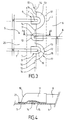
- FIG. 1 a vessel wall having successively from the outside to the inside a bearing wall, an insulation barrier, a sealing barrier , will be described.
- 1 is designated as a whole, an insulating block of the thermal insulation barrier of the tank wall.
- This insulating barrier 1 rests on the carrier wall 2.
- the insulating barrier 1 supports a sealed barrier, which is referred to as the sealed membrane, designated by 4 as a whole.
- the sealed barrier 4 is connected to the insulating barrier 1 via anchor plates 3.
- the insulating barrier 1 is a sandwich composed of two sheets of plywood separated by a polyurethane foam type insulation.
- the anchoring plates 3 are arranged at the edges of the metal sheets 5 and 6, forming the sealed barrier 4, to allow the welding of the edge of a sheet 5, partly covering an anchor plate 3.
- a sheet 5 has corrugations 7 providing some flexibility to the sealing barrier subjected to stress. Indeed, it is advantageous to have a relatively flexible membrane, either to limit the anchoring forces of this membrane or to absorb exceptional stresses, for example, a shell deformation, such as the elongation of the beam of the ship, or contraction due to the temperature of the stored cold liquid. During the thermal contraction and elongation of the ship beam, the waves unfold and weaken the catching areas. This allows among other things not to need a strong anchoring of the membrane on the hull.
- corrugations 7 extend from one edge to the opposite edge of the sheet 5.
- the corrugations 7 are interrupted by a terminal element which we will call caps 9.
- caps 9 the corrugations 7 are hermetically closed to guarantee the tightness of the waterproof membrane 4 in the edge zone of a metal sheet 5 and the corrugations 7.
- the sheet 6 Like the sheet 5, the sheet 6 partially covers the anchor plates 3. In addition, the edge 17 of the sheet 6 overlaps the edge of the sheets 5 in the assembly area. Thus, the edge of a sheet 6 marries the anchoring plate 3 and the sheet 5 and comprises a recess 15 for compensating the thickness of the sheet 5 in the overlap zone 14.
- the two sheets 5 and 6 are, assemblies sealed in the contacting parts.
- the sheet 6 has a stamped strip, which is shifted inwards in the thickness direction relative to the plane of the sheet 6 to cover the edge of an adjacent metal sheet 5.
- a sheet 6 also comprises straight corrugations 8 along the entire length of the sheet 6.
- the corrugations 8 are similar to the corrugations 7 of the sheet 5. In fact, they provide the same functions as those of the corrugations 7. For this, these corrugations 8 are oriented parallel to the corrugations 7 in order to ensure continuity and homogeneity of the behavior of the membrane over the entire surface of the wall of the tank.
- each corrugation 8 is arranged between two corrugations 7 to make it possible to avoid aligning the corrugations 8 with the corrugations 7.
- the corrugations 8 are preferably offset by a half-step with respect to a corrugation 7.
- the corrugations 8 are closed by means of caps 10, sealing the sealed membrane 4.
- each cap 9 extends a corrugation 7 beyond the edge 16 of the sheet 5, between two corrugations 8.
- a cap 9 includes a peripheral sole 18 which marries and is in contact with the anchoring plate 3 in a space forming a light 13 of the anchoring plate 3 not covered by the sheets 5 and 6.
- the peripheral sole 18 overlaps in addition the part
- the cap 9 comprises a corrugation portion 11 which on one side conforms to the corrugation 7 of the metal sheet 5 and gradually decreases to the peripheral flange in a direction oriented from the sheet 5 to the sheet 6.
- This termination of the cap 9 forms a kind of dome.
- other forms of termination may be adopted, such as that of a flat cutaway.
- each cap 10 extends a corrugation 8 beyond the edge 17 of the sheet 6, between two corrugations 8.
- corrugations 7 and 8 increasing the density of corrugations able to cash the forces on the waterproof membrane in the assembly zone of two adjacent sheets 5 and 6.
- the cap 10 comprises a peripheral sole 21 which rests on the plates 5 and 6 on either side of the overlap zone 14.
- the cap 10 comprises a corrugation portion 11 adapted to the corrugation 8 of the sheet 6 and decreasing to the peripheral sole 21 to form a terminal cap 19 also called dome, vault or dome.
- the shaping of the caps 9 and 10 is obtained by folding or stamping.
- corrugations 7b, respectively 8b perpendicular to the corrugations 7, respectively 8 on the plates 5 and 6.
- the corrugations 7b and 8b have characteristics similar or identical to the corrugations 7 and 8.
- These corrugations 7b and 8b conjugated to the corrugations 7, respectively 8, have the function of supporting forces in all directions, especially in the plane constituted by the sealing membrane.
- the sheet 6 further has on the profile of the edge 17, in addition to the recess in the direction of the thickness of the sheet, notches 12, flanking the caps 9 arranged in line with the corrugations 7 of the sheets 5. These notches 12 are arranged alternately with the corrugations 8.
- indentations 12 are intended to facilitate the mounting of a sheet 6 placed on the insulating barrier 1 after the mounting of the plates 5 and caps 9.
- the indentations 12 also have the object of allowing misalignment between the plates 5 and 6.
- the dimension of the notch cutout 12 is made so as to have a sufficient clearance between the caps 9 and the edge of the cut. This game makes it possible to make the same cut for all the sheets and to have no problems of alignment during the implementation of the membrane, because of a too strict tolerance.
- a tank can be carried out according to several procedures.
- prefabricated blocks comprising from the bearing structure towards the inside of the tank, a bearing structure 2 covered in part by an insulation barrier 1 and a sealed barrier 4 are positioned on the site.
- a peripheral zone of a prefabricated block is left accessible for the assembly operations of the two bearing structure blocks, the welding and the verification of the tightness.
- the peripheral zone is filled with an insulator and covered by a waterproof membrane 6.
- the carrier structure is integrally assembled on the site.
- the insulation membrane 1 and the waterproof membrane 4 are arranged on the inner face of the carrier structure. The operation can be optimized by intervening with two teams each leaving at one end of the wall of the tank.
- the indentations 12 are dimensioned to allow a positioning gap tolerance of +/- 2 cm in the longitudinal direction of the anchor plate 3.
- the metal sheets 5 and 6, the caps 9 and 10 are made of stainless steel sheet or aluminum, shaped by folding or stamping. Other metals or alloys are also possible.
- the metal sheets 5 and 6 have a thickness of about 1.2 mm. Other thicknesses are also conceivable, knowing that a thickening of the metal sheets 5 and 6 cause an increase in its cost and generally increases the stiffness of the corrugations.
- the corrugations 7 are preferably finalized during assembly at the factory. To adjust the length of the sealed barrier 4 to the length of the tank, it is possible to cut the length opposite the corrugated closures to the appropriate length.
- the anchoring plate 3 comprises a closure return welded in a sealed manner on the supporting structure. This closure makes it possible to test in the factory the tightness of the pre-assembled part of the block, before assembly on the building site.
- the carrier structure 2 is composed of two sections forming an angle a.
- the two sides are covered by an insulating barrier 1 and a sealing barrier 4.
- the principle is to eliminate the continuity of waves between faces but to maintain the flexibility necessary for the proper functioning of the membrane.
- the insulating barrier 1 is for example a sandwich composed of polyurethane foam sandwiched between two plywood boards, the wood of which is, for example, birch. On the plywood plate facing the inside of the tank is fixed the anchoring member 3.
- the sealing barrier 4 is composed of non-coplanar metal sheets 5 forming a dihedron and corrugated junction parts reported.
- the sheets 5 follow the two sections of the supporting structure 2.
- the sheets 5 are welded to an anchoring member 3.
- the anchoring member 3 disposed at the junction joint of the two sections of the supporting structure 2 is composed of a series of metal plates. These plates 30 form a dihedral whose angle between the two planes is the same alpha ⁇ angle present between the two sides of the dihedral of the supporting structure 2.
- the plates 30 are aligned in the longitudinal direction of the anchoring member. Two adjacent plates 30 each have a transverse edge constituting an interface between the two plates 30. At this interface, a gap 33 is provided to obtain elasticity on the part of the anchor member in the longitudinal direction. Alternatively, the edges at the interface are in contact or welded.
- each anchor plate is arranged perpendicularly to the longitudinal direction of the anchoring member, that is to say approximately parallel to the corrugations 7 of the plates 5.
- the interfaces of the plates are furthermore arranged between two adjacent corrugations 7 of a sheet 5.
- the junction of a sheet 5 with the anchoring member 3 is made with a side plate 35 whose corrugations are closed by caps 24.
- the caps 24 are welded to the sheet 35.
- the caps 24 are straddling the sheet 35 and a plate 30, according to the principle of the embodiment of the figure 1 with the caps 9.
- the edge profile of the edge plate 35 comprises notches 34, alternating with the waves 7. These notches 34 and the interfaces of the plates 30 are generally aligned. These notches 34 make it possible to maintain the elasticity obtained by means of the gaps 33 at the connection of the sealing barrier 4 with the anchoring member 3.
- the corrugated junction pieces reported have a shape to ensure a certain elasticity of the sealed barrier 4.
- an end portion of the corrugations 7 is alternated with a portion of the junction pieces 25 in a zone 37.
- This zone on the figure 8 is plotted as an indication. Indeed, it should be understood that it covers the entire edge of the connections made between the plates 5 and the anchoring member 3, on either side of this anchoring member 3.
- the sealed barrier 4 is capable of undergoing stresses in the region of the anchoring member 3.
- the shape of a piece of corrugated junctions is that of two shells 29 turned upside down, coupled with a bellows 27 of angle a, to allow to collect the forces in the angle of the tank.
- the two shells can be each made in one piece or with a cap 28 welded to a straight wave portion 26. Next, they are assembled to the bellows 27 adapted for the angle value a.
- This arrangement allows greater positioning tolerances between faces since there is more waves to connect.
- a first insulating angle block 31 is placed on the supporting structure 2.
- This block is equipped with the anchoring member 3.
- retrofit blocks 32 of the clearance necessary for mounting the insulating corner block 31 are installed.
- the sealing membrane can then be completed, by adding a sheet 5 ensuring the continuity of the membrane 4, to overlap the plates 30 of the anchoring member 3.
- the assembly welded between the sheet 5 and each plate 30 is made sealingly.
- junction pieces 25 are welded in the same way, to cover and seal the interface between two plates 30.
- a junction piece 25 overlaps the two plates 30 and the interface of the two plates 30 and sheets 5 at the level of the notches 34.
- the edge of the sheet 5 covering the inking member 3 does not have the notches 34.
- the two sections of the supporting structure 2 are coplanar.
- the plates 30 constituting the anchoring member 3 are then flat and the junction parts 25 are straight and do not have bellows.
- a joining piece 25 can then be made in one stamped piece.
- the walls consist of sheets 5 lining the insulating barrier 1. These sheets 5 comprise corrugations 7 and 7b.
- the alignment of the corrugations 7 of the sheets 5 disposed on the wall 90 with the corrugations of the sheets 5 disposed on the inclined wall 91 is problematic. Indeed, it would first be necessary that the pitch between the corrugations of the sheets of the wall 90 and that of the corrugations of the sheets of the wall 91 is adapted as a function of the inclination of the wall 91 also called slope, compared to the horizontal. Then, it would be necessary to ensure the precise alignment for the connection of the corrugations.
- connection zone the force received by the membrane is oriented in the longitudinal direction of the anchoring member. Therefore, on the junction zone, it is necessary to have corrugations of direction perpendicular to the longitudinal direction of the anchoring member for optimum efficiency.
- the criterion of perpendicular orientation of the undulations with respect to the longitudinal directions of the anchoring member is not respected.
- the wall 91 forms an angle of 135 ° with the bottom 92 of the tank.
- the pitch of the undulations on the slope is 480.8mm.
- the corrugations 7, horizontal are diverted at the same angle of 135 °.
- a corner return piece 94 is welded by the edge 96, in the extension of sheets 5. It is welded by the edge 98 to the anchoring member 3.
- the edge 98 is generally parallel to the longitudinal direction of the anchoring member 3.
- the angle return piece 94 makes it possible to extend the corrugations 7 at an angle 93 by means of the corrugations 99.
- the corrugations 99 divert the direction of the corrugations 7, in the plane of the wall 90 according to the angle 93, which is 135 °.
- caps 100 close the corrugations 7b.
- the return by means of the corrugation 99 and the caps 100 make it possible to ensure independence between two faces.
- the flexibility is ensured by the overlap of the corrugations.
- notches 34 are formed on the profile of the assembly edge 98 with the anchoring member 3 . These notches 34 have the same characteristics and functions as in the previous embodiment. These notches 34 arranged in line with the interface between two plates of the anchoring member 3 are covered to ensure sealing by corrugated junction pieces reported.
- the angle of the bellows 27 is 135 °, corresponding to the angle between the two walls 90 and 91.
- the angle gear 94, the sheet 5, the inking member 3 are sealed welded.
- This embodiment therefore also provides mounting with wide tolerances between dissociated faces.
- the angle 93 is adapted according to the inclination of the slope, with the floor. For example, it makes it possible to carry out an angle reference of value 135 °, 161.6 °, 170.6 ° or 173.7 °.
- any other grid step for producing the corrugations is applicable, for example a pitch of 340 mm combined with other steps or identical on all the faces of the tank.
- connection method is also applicable to a wall inclined from the ceiling of the tank to the bottom of the tank. It allows a great freedom in the choice of the geometry of the tank.
- the set of embodiments allows the manufacture of prefabricated sub-assemblies in factories suitable for assembly on the site limiting manual welding in situ. It eliminates the need for precise adjustment problems.
- closure of the corrugations can be obtained by any other means replacing the caps.
- connection weld can therefore be made quickly by a welding robot with a raceway of the welding torch adapted.
- the other welds can be made in prefabrication. All that remains is the connection welds between two coupling membranes, which can be made with a conventional welding robot.
- the technique described above for producing a waterproofing membrane can be used in various types of tanks, for example to form the primary waterproofing membrane, an LNG tank in a land installation or in a floating structure as a LNG carrier or other.
- a cutaway view of a LNG tanker 70 shows a sealed and insulated tank 71 of generally prismatic shape mounted in the double hull 72 of the ship.
- the wall of the tank 71 comprises a primary sealed barrier intended to be in contact with the LNG contained in the tank, a secondary sealed barrier arranged between the primary waterproof barrier and the double hull 72 of the ship, and two insulating barriers arranged respectively between the primary watertight barrier and the secondary watertight barrier and between the secondary watertight barrier and the double hull 72.
- loading / unloading lines 73 arranged on the upper deck of the ship can be connected, by means of appropriate connectors, to a marine or port terminal to transfer a cargo of LNG from or to the tank 71.
- the figure 12 represents an example of a marine terminal comprising a loading and unloading station 75, an underwater pipe 76 and an onshore installation 77.
- the loading and unloading station 75 is an off-shore fixed installation comprising a movable arm 74 and a tower 78 which supports the movable arm 74.
- the movable arm 74 carries a bundle of insulated flexible pipes 79 that can connect to the loading / unloading pipes 73.
- the movable arm 74 can be adapted to all gauges LNG carriers.
- a connection pipe (not shown) extends inside the tower 78.
- the loading and unloading station 75 enables the loading and unloading of the LNG tank 70 from or to the shore facility 77.
- the underwater line 76 allows the transfer of the liquefied gas between the loading or unloading station 75 and the onshore installation 77 over a large distance, for example 5 km, which makes it possible to keep the tanker vessel 70 at great distance from the coast during the loading and unloading operations.
- pumps on board the ship 70 and / or pumps equipping the shore installation 77 and / or pumps equipping the loading and unloading station 75 are used.
Landscapes
- Engineering & Computer Science (AREA)
- Mechanical Engineering (AREA)
- Physics & Mathematics (AREA)
- Chemical & Material Sciences (AREA)
- Combustion & Propulsion (AREA)
- Ocean & Marine Engineering (AREA)
- Thermal Sciences (AREA)
- General Engineering & Computer Science (AREA)
- Fluid Mechanics (AREA)
- Filling Or Discharging Of Gas Storage Vessels (AREA)
Applications Claiming Priority (2)
| Application Number | Priority Date | Filing Date | Title |
|---|---|---|---|
| FR1353262A FR3004507B1 (fr) | 2013-04-11 | 2013-04-11 | Decouplage des ondulations d'une barriere etanche |
| PCT/FR2014/050819 WO2014167228A2 (fr) | 2013-04-11 | 2014-04-04 | Découplage des ondulations d'une barrière étanche |
Publications (2)
| Publication Number | Publication Date |
|---|---|
| EP2984382A2 EP2984382A2 (fr) | 2016-02-17 |
| EP2984382B1 true EP2984382B1 (fr) | 2019-05-08 |
Family
ID=48656141
Family Applications (1)
| Application Number | Title | Priority Date | Filing Date |
|---|---|---|---|
| EP14720660.1A Active EP2984382B1 (fr) | 2013-04-11 | 2014-04-04 | Découplage des ondulations d'une barrière étanche |
Country Status (12)
| Country | Link |
|---|---|
| US (2) | US10378694B2 (ja) |
| EP (1) | EP2984382B1 (ja) |
| JP (1) | JP6291566B2 (ja) |
| KR (2) | KR102306575B1 (ja) |
| CN (1) | CN105283704B (ja) |
| AU (1) | AU2014252973B2 (ja) |
| ES (1) | ES2732288T3 (ja) |
| FR (1) | FR3004507B1 (ja) |
| MY (1) | MY188268A (ja) |
| RU (1) | RU2650243C2 (ja) |
| SG (1) | SG11201508308UA (ja) |
| WO (1) | WO2014167228A2 (ja) |
Families Citing this family (21)
| Publication number | Priority date | Publication date | Assignee | Title |
|---|---|---|---|---|
| FR3004507B1 (fr) | 2013-04-11 | 2019-04-26 | Gaztransport Et Technigaz | Decouplage des ondulations d'une barriere etanche |
| FR3004510B1 (fr) * | 2013-04-12 | 2016-12-09 | Gaztransport Et Technigaz | Cuve etanche et thermiquement isolante de stockage d'un fluide |
| FR3009745B1 (fr) * | 2013-08-15 | 2016-01-29 | Gaztransp Et Technigaz | Cuve etanche et thermiquement isolante comportant une piece d'angle |
| FR3049678B1 (fr) * | 2016-04-01 | 2018-04-13 | Gaztransport Et Technigaz | Bloc de bordure thermiquement isolant pour la fabrication d'une paroi de cuve |
| FR3050008B1 (fr) * | 2016-04-11 | 2018-04-27 | Gaztransport Et Technigaz | Cuve etanche a membranes d'etancheite ondulees |
| CN205908999U (zh) * | 2016-07-18 | 2017-01-25 | 江苏兰宇保温科技有限公司 | 具有泄漏追踪功能的低温储罐的保温内层结构 |
| FR3054872B1 (fr) | 2016-08-02 | 2018-08-17 | Gaztransport Et Technigaz | Structure de paroi etanche |
| FR3054871B1 (fr) | 2016-08-02 | 2018-12-07 | Gaztransport Et Technigaz | Structure de paroi etanche |
| FR3069043B1 (fr) * | 2017-07-13 | 2020-10-30 | Gaztransport Et Technigaz | Cuve etanche et thermiquement isolante a bande de support incurvee |
| FR3069903B1 (fr) * | 2017-08-07 | 2019-08-30 | Gaztransport Et Technigaz | Cuve etanche et themiquement isolante |
| US11560981B2 (en) | 2017-12-28 | 2023-01-24 | Daewoo Shipbuilding & Marine Engineering Co., Ltd. | Membrane finishing sheet and membrane insulation structure comprising the same |
| KR102020965B1 (ko) * | 2017-12-29 | 2019-09-11 | 대우조선해양 주식회사 | 멤브레인 접합구조 및 상기 멤브레인 접합구조를 포함하는 액화가스 저장탱크 |
| FR3077278B1 (fr) * | 2018-02-01 | 2020-02-07 | Gaztransport Et Technigaz | Paroi etanche a membrane ondulee renforcee |
| FR3082593B1 (fr) * | 2018-06-13 | 2020-06-19 | Gaztransport Et Technigaz | Cuve etanche munie d'un element de jonction ondule |
| FR3082594B1 (fr) * | 2018-06-13 | 2021-12-31 | Gaztransport Et Technigaz | Cuve etanche et thermiquement isolante |
| FR3084645B1 (fr) * | 2018-08-06 | 2021-01-15 | Gaztransport Et Technigaz | Structure d'angle pour une cuve etanche et thermiquement isolante |
| FR3089597B1 (fr) * | 2018-12-06 | 2020-11-20 | Gaztransport Et Technigaz | Cuve étanche et thermiquement isolante |
| DE102019125403A1 (de) * | 2019-09-20 | 2021-03-25 | Kautex Textron Gmbh & Co. Kg | Kunststoffbehälter für kraftfahrzeuge mit zumindest einer versteifungsstruktur |
| FR3102228B1 (fr) | 2019-10-18 | 2021-09-10 | Gaztransport Et Technigaz | Cuve étanche et thermiquement isolante |
| CN112032550B (zh) * | 2020-11-06 | 2021-03-26 | 中太海事技术(上海)有限公司 | 一种用于液化天然气储存的双金属低温薄膜储存舱 |
| CN117818820A (zh) * | 2024-03-06 | 2024-04-05 | 沪东中华造船(集团)有限公司 | 一种薄膜型液货围护系统及lng船 |
Family Cites Families (22)
| Publication number | Priority date | Publication date | Assignee | Title |
|---|---|---|---|---|
| BE639626A (ja) * | 1963-05-06 | |||
| FR2691520B1 (fr) * | 1992-05-20 | 1994-09-02 | Technigaz Ste Nle | Structure préfabriquée de formation de parois étanches et thermiquement isolantes pour enceinte de confinement d'un fluide à très basse température. |
| JP3249283B2 (ja) * | 1994-02-18 | 2002-01-21 | 三菱重工業株式会社 | 低温タンクのメンブレン構造 |
| FR2735847B1 (fr) * | 1995-06-22 | 1997-08-14 | Korea Gas Corp | Membrane pour reservoir de stockage de gaz naturel liquefie |
| FR2739675B1 (fr) * | 1995-10-05 | 1997-11-07 | Gaztransport Et Technigaz | Cuve terrestre pour le stockage du liquide a basse temperature |
| JP2002181288A (ja) * | 2000-12-14 | 2002-06-26 | Ishikawajima Harima Heavy Ind Co Ltd | 低温液化ガスメンブレンタンク |
| FR2861060B1 (fr) * | 2003-10-16 | 2006-01-06 | Gaz Transport & Technigaz | Structure de paroi etanche et cuve munie d'une telle structure |
| ATE480735T1 (de) * | 2004-07-06 | 2010-09-15 | Shell Int Research | Behälter zur lagerung von flüssiggas |
| FR2877639B1 (fr) * | 2004-11-10 | 2006-12-15 | Gaz Transp Et Technigaz Soc Pa | Cuve etanche et thermiquement isolee integree a la stucture porteuse d'un navire |
| JP4616279B2 (ja) | 2004-12-08 | 2011-01-19 | コリア ガス コーポレイション | 液化天然ガスの保存タンク及びその製造方法 |
| KR100644217B1 (ko) * | 2006-04-20 | 2006-11-10 | 한국가스공사 | 개선된 단열구조를 갖는 액화천연가스 저장탱크 및 그제조방법 |
| FR2903165B1 (fr) * | 2006-06-30 | 2008-09-05 | Gaz Transport & Technigaz | Panneau prefabrique avec film protecteur |
| JP4451439B2 (ja) * | 2006-09-01 | 2010-04-14 | 韓国ガス公社 | 液化天然ガスの貯蔵タンクを形成するための構造体 |
| FR2909356B1 (fr) * | 2006-11-30 | 2009-01-16 | Gaztransp Et Technigaz Soc Par | Fixation par collage de blocs isolants pour cuve de transport de gaz liquefies a l'aide de cordons ondules |
| KR100782737B1 (ko) * | 2007-05-29 | 2007-12-05 | 현대중공업 주식회사 | 용접형 2차 방벽을 구비하는 액화천연가스 저장용기용단열시스템과 그 시공방법 |
| FR2931535B1 (fr) * | 2008-05-21 | 2010-08-20 | Gaztransp Et Technigaz | Fixation par collage de blocs isolants pour cuve de stockage de gaz liquefies a l'aide de cordons ondules |
| JP5174856B2 (ja) * | 2010-06-16 | 2013-04-03 | 鹿島建設株式会社 | 防液堤一体型低温タンクの冷熱抵抗緩和材の設置方法 |
| FR2961580B1 (fr) * | 2010-06-17 | 2012-07-13 | Gaztransport Et Technigaz | Cuve etanche et isolante comportant un pied de support |
| FR2963818B1 (fr) * | 2010-08-11 | 2014-01-03 | Gaztransp Et Technigaz | Structure de paroi etanche |
| FR2973098B1 (fr) * | 2011-03-22 | 2014-05-02 | Gaztransp Et Technigaz | Cuve etanche et thermiquement isolante |
| FR3004507B1 (fr) | 2013-04-11 | 2019-04-26 | Gaztransport Et Technigaz | Decouplage des ondulations d'une barriere etanche |
| FR3004511B1 (fr) * | 2013-04-15 | 2016-12-30 | Gaztransport Et Technigaz | Cuve etanche et thermiquement isolante |
-
2013
- 2013-04-11 FR FR1353262A patent/FR3004507B1/fr active Active
-
2014
- 2014-04-04 SG SG11201508308UA patent/SG11201508308UA/en unknown
- 2014-04-04 WO PCT/FR2014/050819 patent/WO2014167228A2/fr active Application Filing
- 2014-04-04 CN CN201480020735.9A patent/CN105283704B/zh active Active
- 2014-04-04 EP EP14720660.1A patent/EP2984382B1/fr active Active
- 2014-04-04 JP JP2016507033A patent/JP6291566B2/ja active Active
- 2014-04-04 AU AU2014252973A patent/AU2014252973B2/en active Active
- 2014-04-04 MY MYPI2015703562A patent/MY188268A/en unknown
- 2014-04-04 KR KR1020217006726A patent/KR102306575B1/ko active IP Right Grant
- 2014-04-04 US US14/783,755 patent/US10378694B2/en active Active
- 2014-04-04 ES ES14720660T patent/ES2732288T3/es active Active
- 2014-04-04 KR KR1020157031342A patent/KR102226313B1/ko active IP Right Grant
- 2014-04-04 RU RU2015145298A patent/RU2650243C2/ru active
-
2019
- 2019-07-10 US US16/507,677 patent/US11073241B2/en active Active
Non-Patent Citations (1)
| Title |
|---|
| None * |
Also Published As
| Publication number | Publication date |
|---|---|
| US10378694B2 (en) | 2019-08-13 |
| US11073241B2 (en) | 2021-07-27 |
| ES2732288T3 (es) | 2019-11-21 |
| SG11201508308UA (en) | 2015-11-27 |
| US20160069514A1 (en) | 2016-03-10 |
| RU2015145298A (ru) | 2017-05-16 |
| AU2014252973A1 (en) | 2015-11-05 |
| AU2014252973B2 (en) | 2016-07-21 |
| EP2984382A2 (fr) | 2016-02-17 |
| FR3004507A1 (fr) | 2014-10-17 |
| WO2014167228A2 (fr) | 2014-10-16 |
| CN105283704A (zh) | 2016-01-27 |
| WO2014167228A3 (fr) | 2015-04-16 |
| US20190331297A1 (en) | 2019-10-31 |
| KR102226313B1 (ko) | 2021-03-10 |
| KR20210028746A (ko) | 2021-03-12 |
| JP2016515986A (ja) | 2016-06-02 |
| KR102306575B1 (ko) | 2021-09-29 |
| RU2650243C2 (ru) | 2018-04-11 |
| CN105283704B (zh) | 2017-04-26 |
| MY188268A (en) | 2021-11-24 |
| KR20150141984A (ko) | 2015-12-21 |
| FR3004507B1 (fr) | 2019-04-26 |
| JP6291566B2 (ja) | 2018-03-14 |
Similar Documents
| Publication | Publication Date | Title |
|---|---|---|
| EP2984382B1 (fr) | Découplage des ondulations d'une barrière étanche | |
| EP2984384B1 (fr) | Structure d'angle d'une cuve etanche et thermiquement isolante de stockage d'un fluide | |
| EP3320256B1 (fr) | Cuve etanche et thermiquement isolante ayant une membrane d'etancheite secondaire equipee d'un arrangement d'angle a toles metalliques ondulees | |
| EP2984383B1 (fr) | Cuve etanche et thermiquement isolante de stockage d'un fluide | |
| EP3033564B1 (fr) | Cuve etanche et thermiquement isolante comportant une piece d'angle | |
| FR3058498A1 (fr) | Structure d'angle d'une cuve etanche et thermiquement isolante et son procede d'assemblage | |
| EP3473915B1 (fr) | Cuve etanche et thermiquement isolante | |
| EP3425261B1 (fr) | Cuve etanche et thermiquement isolante | |
| EP3365592B1 (fr) | Cuve comprenant des blocs isolants de coin equipes de fentes de relaxation | |
| FR2987099A1 (fr) | Cuve etanche et thermiquement isolante comportant une piece d'angle | |
| EP3425260A1 (fr) | Cuve etanche et thermiquement isolante comportant une corniere | |
| WO2020039134A1 (fr) | Paroi de cuve étanche et thermiquement isolante | |
| WO2018024982A1 (fr) | Structure de paroi etanche | |
| FR3082596A1 (fr) | Cuve etanche et thermiquement isolante a ondulations continues dans le dome liquide | |
| EP3665414B1 (fr) | Cuve etanche et thermiquement isolante | |
| WO2019239053A1 (fr) | Cuve etanche munie d'un element de jonction ondule | |
| EP3948055B1 (fr) | Installation de stockage pour gaz liquéfié | |
| EP3645933A1 (fr) | Membrane etanche et procede d'assemblage d'une membrane etanche | |
| WO2021074413A1 (fr) | Poutre de raccordement pour une cuve etanche et thermiquement isolante de stockage de gaz liquefie | |
| FR3131360A1 (fr) | Installation de stockage pour gaz liquéfié |
Legal Events
| Date | Code | Title | Description |
|---|---|---|---|
| PUAI | Public reference made under article 153(3) epc to a published international application that has entered the european phase |
Free format text: ORIGINAL CODE: 0009012 |
|
| 17P | Request for examination filed |
Effective date: 20150924 |
|
| AK | Designated contracting states |
Kind code of ref document: A2 Designated state(s): AL AT BE BG CH CY CZ DE DK EE ES FI FR GB GR HR HU IE IS IT LI LT LU LV MC MK MT NL NO PL PT RO RS SE SI SK SM TR |
|
| AX | Request for extension of the european patent |
Extension state: BA ME |
|
| RIN1 | Information on inventor provided before grant (corrected) |
Inventor name: HERRY, MICKAEL Inventor name: BOYEAU, MARC Inventor name: PHILIPPE, ANTOINE Inventor name: DELANOE, SEBASTIEN Inventor name: PESQUET, FABIEN Inventor name: LONGUET, VIRGINIE |
|
| DAX | Request for extension of the european patent (deleted) | ||
| RAP1 | Party data changed (applicant data changed or rights of an application transferred) |
Owner name: GAZTRANSPORT ET TECHNIGAZ |
|
| GRAP | Despatch of communication of intention to grant a patent |
Free format text: ORIGINAL CODE: EPIDOSNIGR1 |
|
| STAA | Information on the status of an ep patent application or granted ep patent |
Free format text: STATUS: GRANT OF PATENT IS INTENDED |
|
| INTG | Intention to grant announced |
Effective date: 20181029 |
|
| GRAS | Grant fee paid |
Free format text: ORIGINAL CODE: EPIDOSNIGR3 |
|
| GRAJ | Information related to disapproval of communication of intention to grant by the applicant or resumption of examination proceedings by the epo deleted |
Free format text: ORIGINAL CODE: EPIDOSDIGR1 |
|
| GRAL | Information related to payment of fee for publishing/printing deleted |
Free format text: ORIGINAL CODE: EPIDOSDIGR3 |
|
| STAA | Information on the status of an ep patent application or granted ep patent |
Free format text: STATUS: REQUEST FOR EXAMINATION WAS MADE |
|
| GRAR | Information related to intention to grant a patent recorded |
Free format text: ORIGINAL CODE: EPIDOSNIGR71 |
|
| STAA | Information on the status of an ep patent application or granted ep patent |
Free format text: STATUS: GRANT OF PATENT IS INTENDED |
|
| INTC | Intention to grant announced (deleted) | ||
| GRAA | (expected) grant |
Free format text: ORIGINAL CODE: 0009210 |
|
| STAA | Information on the status of an ep patent application or granted ep patent |
Free format text: STATUS: THE PATENT HAS BEEN GRANTED |
|
| INTG | Intention to grant announced |
Effective date: 20190328 |
|
| AK | Designated contracting states |
Kind code of ref document: B1 Designated state(s): AL AT BE BG CH CY CZ DE DK EE ES FI FR GB GR HR HU IE IS IT LI LT LU LV MC MK MT NL NO PL PT RO RS SE SI SK SM TR |
|
| REG | Reference to a national code |
Ref country code: GB Ref legal event code: FG4D Free format text: NOT ENGLISH |
|
| REG | Reference to a national code |
Ref country code: CH Ref legal event code: EP Ref country code: AT Ref legal event code: REF Ref document number: 1130679 Country of ref document: AT Kind code of ref document: T Effective date: 20190515 |
|
| REG | Reference to a national code |
Ref country code: IE Ref legal event code: FG4D Free format text: LANGUAGE OF EP DOCUMENT: FRENCH |
|
| REG | Reference to a national code |
Ref country code: DE Ref legal event code: R096 Ref document number: 602014046263 Country of ref document: DE |
|
| REG | Reference to a national code |
Ref country code: NL Ref legal event code: FP |
|
| REG | Reference to a national code |
Ref country code: LT Ref legal event code: MG4D |
|
| PG25 | Lapsed in a contracting state [announced via postgrant information from national office to epo] |
Ref country code: HR Free format text: LAPSE BECAUSE OF FAILURE TO SUBMIT A TRANSLATION OF THE DESCRIPTION OR TO PAY THE FEE WITHIN THE PRESCRIBED TIME-LIMIT Effective date: 20190508 Ref country code: SE Free format text: LAPSE BECAUSE OF FAILURE TO SUBMIT A TRANSLATION OF THE DESCRIPTION OR TO PAY THE FEE WITHIN THE PRESCRIBED TIME-LIMIT Effective date: 20190508 Ref country code: LT Free format text: LAPSE BECAUSE OF FAILURE TO SUBMIT A TRANSLATION OF THE DESCRIPTION OR TO PAY THE FEE WITHIN THE PRESCRIBED TIME-LIMIT Effective date: 20190508 Ref country code: NO Free format text: LAPSE BECAUSE OF FAILURE TO SUBMIT A TRANSLATION OF THE DESCRIPTION OR TO PAY THE FEE WITHIN THE PRESCRIBED TIME-LIMIT Effective date: 20190808 Ref country code: PT Free format text: LAPSE BECAUSE OF FAILURE TO SUBMIT A TRANSLATION OF THE DESCRIPTION OR TO PAY THE FEE WITHIN THE PRESCRIBED TIME-LIMIT Effective date: 20190908 Ref country code: FI Free format text: LAPSE BECAUSE OF FAILURE TO SUBMIT A TRANSLATION OF THE DESCRIPTION OR TO PAY THE FEE WITHIN THE PRESCRIBED TIME-LIMIT Effective date: 20190508 Ref country code: AL Free format text: LAPSE BECAUSE OF FAILURE TO SUBMIT A TRANSLATION OF THE DESCRIPTION OR TO PAY THE FEE WITHIN THE PRESCRIBED TIME-LIMIT Effective date: 20190508 |
|
| REG | Reference to a national code |
Ref country code: ES Ref legal event code: FG2A Ref document number: 2732288 Country of ref document: ES Kind code of ref document: T3 Effective date: 20191121 |
|
| PG25 | Lapsed in a contracting state [announced via postgrant information from national office to epo] |
Ref country code: LV Free format text: LAPSE BECAUSE OF FAILURE TO SUBMIT A TRANSLATION OF THE DESCRIPTION OR TO PAY THE FEE WITHIN THE PRESCRIBED TIME-LIMIT Effective date: 20190508 Ref country code: GR Free format text: LAPSE BECAUSE OF FAILURE TO SUBMIT A TRANSLATION OF THE DESCRIPTION OR TO PAY THE FEE WITHIN THE PRESCRIBED TIME-LIMIT Effective date: 20190809 Ref country code: BG Free format text: LAPSE BECAUSE OF FAILURE TO SUBMIT A TRANSLATION OF THE DESCRIPTION OR TO PAY THE FEE WITHIN THE PRESCRIBED TIME-LIMIT Effective date: 20190808 Ref country code: RS Free format text: LAPSE BECAUSE OF FAILURE TO SUBMIT A TRANSLATION OF THE DESCRIPTION OR TO PAY THE FEE WITHIN THE PRESCRIBED TIME-LIMIT Effective date: 20190508 |
|
| REG | Reference to a national code |
Ref country code: AT Ref legal event code: MK05 Ref document number: 1130679 Country of ref document: AT Kind code of ref document: T Effective date: 20190508 |
|
| PG25 | Lapsed in a contracting state [announced via postgrant information from national office to epo] |
Ref country code: RO Free format text: LAPSE BECAUSE OF FAILURE TO SUBMIT A TRANSLATION OF THE DESCRIPTION OR TO PAY THE FEE WITHIN THE PRESCRIBED TIME-LIMIT Effective date: 20190508 Ref country code: CZ Free format text: LAPSE BECAUSE OF FAILURE TO SUBMIT A TRANSLATION OF THE DESCRIPTION OR TO PAY THE FEE WITHIN THE PRESCRIBED TIME-LIMIT Effective date: 20190508 Ref country code: DK Free format text: LAPSE BECAUSE OF FAILURE TO SUBMIT A TRANSLATION OF THE DESCRIPTION OR TO PAY THE FEE WITHIN THE PRESCRIBED TIME-LIMIT Effective date: 20190508 Ref country code: EE Free format text: LAPSE BECAUSE OF FAILURE TO SUBMIT A TRANSLATION OF THE DESCRIPTION OR TO PAY THE FEE WITHIN THE PRESCRIBED TIME-LIMIT Effective date: 20190508 Ref country code: AT Free format text: LAPSE BECAUSE OF FAILURE TO SUBMIT A TRANSLATION OF THE DESCRIPTION OR TO PAY THE FEE WITHIN THE PRESCRIBED TIME-LIMIT Effective date: 20190508 Ref country code: SK Free format text: LAPSE BECAUSE OF FAILURE TO SUBMIT A TRANSLATION OF THE DESCRIPTION OR TO PAY THE FEE WITHIN THE PRESCRIBED TIME-LIMIT Effective date: 20190508 |
|
| REG | Reference to a national code |
Ref country code: DE Ref legal event code: R097 Ref document number: 602014046263 Country of ref document: DE |
|
| PG25 | Lapsed in a contracting state [announced via postgrant information from national office to epo] |
Ref country code: IT Free format text: LAPSE BECAUSE OF FAILURE TO SUBMIT A TRANSLATION OF THE DESCRIPTION OR TO PAY THE FEE WITHIN THE PRESCRIBED TIME-LIMIT Effective date: 20190508 Ref country code: SM Free format text: LAPSE BECAUSE OF FAILURE TO SUBMIT A TRANSLATION OF THE DESCRIPTION OR TO PAY THE FEE WITHIN THE PRESCRIBED TIME-LIMIT Effective date: 20190508 |
|
| PLBE | No opposition filed within time limit |
Free format text: ORIGINAL CODE: 0009261 |
|
| STAA | Information on the status of an ep patent application or granted ep patent |
Free format text: STATUS: NO OPPOSITION FILED WITHIN TIME LIMIT |
|
| PG25 | Lapsed in a contracting state [announced via postgrant information from national office to epo] |
Ref country code: TR Free format text: LAPSE BECAUSE OF FAILURE TO SUBMIT A TRANSLATION OF THE DESCRIPTION OR TO PAY THE FEE WITHIN THE PRESCRIBED TIME-LIMIT Effective date: 20190508 |
|
| 26N | No opposition filed |
Effective date: 20200211 |
|
| PG25 | Lapsed in a contracting state [announced via postgrant information from national office to epo] |
Ref country code: PL Free format text: LAPSE BECAUSE OF FAILURE TO SUBMIT A TRANSLATION OF THE DESCRIPTION OR TO PAY THE FEE WITHIN THE PRESCRIBED TIME-LIMIT Effective date: 20190508 |
|
| PG25 | Lapsed in a contracting state [announced via postgrant information from national office to epo] |
Ref country code: SI Free format text: LAPSE BECAUSE OF FAILURE TO SUBMIT A TRANSLATION OF THE DESCRIPTION OR TO PAY THE FEE WITHIN THE PRESCRIBED TIME-LIMIT Effective date: 20190508 |
|
| PG25 | Lapsed in a contracting state [announced via postgrant information from national office to epo] |
Ref country code: MC Free format text: LAPSE BECAUSE OF FAILURE TO SUBMIT A TRANSLATION OF THE DESCRIPTION OR TO PAY THE FEE WITHIN THE PRESCRIBED TIME-LIMIT Effective date: 20190508 |
|
| REG | Reference to a national code |
Ref country code: CH Ref legal event code: PL |
|
| PG25 | Lapsed in a contracting state [announced via postgrant information from national office to epo] |
Ref country code: LU Free format text: LAPSE BECAUSE OF NON-PAYMENT OF DUE FEES Effective date: 20200404 Ref country code: LI Free format text: LAPSE BECAUSE OF NON-PAYMENT OF DUE FEES Effective date: 20200430 Ref country code: CH Free format text: LAPSE BECAUSE OF NON-PAYMENT OF DUE FEES Effective date: 20200430 |
|
| REG | Reference to a national code |
Ref country code: BE Ref legal event code: MM Effective date: 20200430 |
|
| PG25 | Lapsed in a contracting state [announced via postgrant information from national office to epo] |
Ref country code: BE Free format text: LAPSE BECAUSE OF NON-PAYMENT OF DUE FEES Effective date: 20200430 |
|
| GBPC | Gb: european patent ceased through non-payment of renewal fee |
Effective date: 20200404 |
|
| PG25 | Lapsed in a contracting state [announced via postgrant information from national office to epo] |
Ref country code: GB Free format text: LAPSE BECAUSE OF NON-PAYMENT OF DUE FEES Effective date: 20200404 Ref country code: IE Free format text: LAPSE BECAUSE OF NON-PAYMENT OF DUE FEES Effective date: 20200404 |
|
| PG25 | Lapsed in a contracting state [announced via postgrant information from national office to epo] |
Ref country code: MT Free format text: LAPSE BECAUSE OF FAILURE TO SUBMIT A TRANSLATION OF THE DESCRIPTION OR TO PAY THE FEE WITHIN THE PRESCRIBED TIME-LIMIT Effective date: 20190508 Ref country code: CY Free format text: LAPSE BECAUSE OF FAILURE TO SUBMIT A TRANSLATION OF THE DESCRIPTION OR TO PAY THE FEE WITHIN THE PRESCRIBED TIME-LIMIT Effective date: 20190508 |
|
| PG25 | Lapsed in a contracting state [announced via postgrant information from national office to epo] |
Ref country code: MK Free format text: LAPSE BECAUSE OF FAILURE TO SUBMIT A TRANSLATION OF THE DESCRIPTION OR TO PAY THE FEE WITHIN THE PRESCRIBED TIME-LIMIT Effective date: 20190508 Ref country code: IS Free format text: LAPSE BECAUSE OF FAILURE TO SUBMIT A TRANSLATION OF THE DESCRIPTION OR TO PAY THE FEE WITHIN THE PRESCRIBED TIME-LIMIT Effective date: 20190908 |
|
| P01 | Opt-out of the competence of the unified patent court (upc) registered |
Effective date: 20230602 |
|
| PGFP | Annual fee paid to national office [announced via postgrant information from national office to epo] |
Ref country code: FR Payment date: 20230425 Year of fee payment: 10 Ref country code: ES Payment date: 20230504 Year of fee payment: 10 Ref country code: DE Payment date: 20230412 Year of fee payment: 10 |
|
| PGFP | Annual fee paid to national office [announced via postgrant information from national office to epo] |
Ref country code: NL Payment date: 20240325 Year of fee payment: 11 |