EP2982832B1 - Rotating machine - Google Patents
Rotating machine Download PDFInfo
- Publication number
- EP2982832B1 EP2982832B1 EP14779746.8A EP14779746A EP2982832B1 EP 2982832 B1 EP2982832 B1 EP 2982832B1 EP 14779746 A EP14779746 A EP 14779746A EP 2982832 B1 EP2982832 B1 EP 2982832B1
- Authority
- EP
- European Patent Office
- Prior art keywords
- swirl
- swirl flow
- breakers
- rotor
- rotating machine
- Prior art date
- Legal status (The legal status is an assumption and is not a legal conclusion. Google has not performed a legal analysis and makes no representation as to the accuracy of the status listed.)
- Not-in-force
Links
Images


Classifications
-
- F—MECHANICAL ENGINEERING; LIGHTING; HEATING; WEAPONS; BLASTING
- F01—MACHINES OR ENGINES IN GENERAL; ENGINE PLANTS IN GENERAL; STEAM ENGINES
- F01D—NON-POSITIVE DISPLACEMENT MACHINES OR ENGINES, e.g. STEAM TURBINES
- F01D11/00—Preventing or minimising internal leakage of working-fluid, e.g. between stages
- F01D11/08—Preventing or minimising internal leakage of working-fluid, e.g. between stages for sealing space between rotor blade tips and stator
-
- F—MECHANICAL ENGINEERING; LIGHTING; HEATING; WEAPONS; BLASTING
- F01—MACHINES OR ENGINES IN GENERAL; ENGINE PLANTS IN GENERAL; STEAM ENGINES
- F01D—NON-POSITIVE DISPLACEMENT MACHINES OR ENGINES, e.g. STEAM TURBINES
- F01D25/00—Component parts, details, or accessories, not provided for in, or of interest apart from, other groups
- F01D25/24—Casings; Casing parts, e.g. diaphragms, casing fastenings
-
- F—MECHANICAL ENGINEERING; LIGHTING; HEATING; WEAPONS; BLASTING
- F01—MACHINES OR ENGINES IN GENERAL; ENGINE PLANTS IN GENERAL; STEAM ENGINES
- F01D—NON-POSITIVE DISPLACEMENT MACHINES OR ENGINES, e.g. STEAM TURBINES
- F01D5/00—Blades; Blade-carrying members; Heating, heat-insulating, cooling or antivibration means on the blades or the members
- F01D5/02—Blade-carrying members, e.g. rotors
-
- F—MECHANICAL ENGINEERING; LIGHTING; HEATING; WEAPONS; BLASTING
- F01—MACHINES OR ENGINES IN GENERAL; ENGINE PLANTS IN GENERAL; STEAM ENGINES
- F01D—NON-POSITIVE DISPLACEMENT MACHINES OR ENGINES, e.g. STEAM TURBINES
- F01D5/00—Blades; Blade-carrying members; Heating, heat-insulating, cooling or antivibration means on the blades or the members
- F01D5/12—Blades
- F01D5/22—Blade-to-blade connections, e.g. for damping vibrations
- F01D5/225—Blade-to-blade connections, e.g. for damping vibrations by shrouding
-
- F—MECHANICAL ENGINEERING; LIGHTING; HEATING; WEAPONS; BLASTING
- F05—INDEXING SCHEMES RELATING TO ENGINES OR PUMPS IN VARIOUS SUBCLASSES OF CLASSES F01-F04
- F05D—INDEXING SCHEME FOR ASPECTS RELATING TO NON-POSITIVE-DISPLACEMENT MACHINES OR ENGINES, GAS-TURBINES OR JET-PROPULSION PLANTS
- F05D2220/00—Application
- F05D2220/30—Application in turbines
- F05D2220/31—Application in turbines in steam turbines
-
- F—MECHANICAL ENGINEERING; LIGHTING; HEATING; WEAPONS; BLASTING
- F05—INDEXING SCHEMES RELATING TO ENGINES OR PUMPS IN VARIOUS SUBCLASSES OF CLASSES F01-F04
- F05D—INDEXING SCHEME FOR ASPECTS RELATING TO NON-POSITIVE-DISPLACEMENT MACHINES OR ENGINES, GAS-TURBINES OR JET-PROPULSION PLANTS
- F05D2220/00—Application
- F05D2220/30—Application in turbines
- F05D2220/32—Application in turbines in gas turbines
-
- F—MECHANICAL ENGINEERING; LIGHTING; HEATING; WEAPONS; BLASTING
- F05—INDEXING SCHEMES RELATING TO ENGINES OR PUMPS IN VARIOUS SUBCLASSES OF CLASSES F01-F04
- F05D—INDEXING SCHEME FOR ASPECTS RELATING TO NON-POSITIVE-DISPLACEMENT MACHINES OR ENGINES, GAS-TURBINES OR JET-PROPULSION PLANTS
- F05D2240/00—Components
- F05D2240/55—Seals
-
- F—MECHANICAL ENGINEERING; LIGHTING; HEATING; WEAPONS; BLASTING
- F05—INDEXING SCHEMES RELATING TO ENGINES OR PUMPS IN VARIOUS SUBCLASSES OF CLASSES F01-F04
- F05D—INDEXING SCHEME FOR ASPECTS RELATING TO NON-POSITIVE-DISPLACEMENT MACHINES OR ENGINES, GAS-TURBINES OR JET-PROPULSION PLANTS
- F05D2260/00—Function
- F05D2260/60—Fluid transfer
Definitions
- the present invention relates to a rotating machine, and more particularly, to a rotating machine including a seal mechanism configured to reduce leakage loss.
- a seal mechanism is used (for example, see Japanese Unexamined Patent Application, First Publication No. 2006-104952 ).
- a technology of forming a seal member such as a sealing fin or the like extending from an inner circumference of the casing toward the rotor blade is known.
- GB 1 505 534 A discloses a method for raising the dynamic output limit of steam or gas powered turbines or compressors with proximity seals arranged in gaps between rotating and fixed components, wherein a circumferential component of the gap flow is reduced substantially to zero, is reversed in its sense of direction, or is increased in the reverse sense of direction.
- WO 2012/001997 A1 discloses a rotating machine with the pre-characterizing features of claims 1 and 6.
- the self-excited vibration is caused by irregular pressure distribution generated in a cavity between sealing fins in a circumferential direction when a flow (a swirl flow) having a strong velocity component in a circumferential direction (a swirl component, a tangential velocity component) after passing the stator blades passes the sealing fins.
- a structure configured to reduce/attenuate a swirl component is needed in a seal mechanism of a rotating machine.
- a structure similar to an apparatus disclosed in US Patent No. 7004475 , a technology of installing a baffle plate in a rotor blade tip cavity is known.
- a seal member used in the apparatus has a honeycomb structure constituted by sealing fins and a baffle plate.
- the honeycomb structure is a structure in which the sealing fins are divided by the baffle plate extending in the axial direction and the working fluid does not enter the structure because of the continuous baffle plate, a swirl reduction effect is low.
- An object of the present invention is directed to providing a rotating machine including a seal mechanism capable of enhancing a reduction effect of a swirl flow.
- a rotating machine includes: a rotor having a rotor main body that rotates about an axis thereof, and a rotor blade disposed to extend from the rotor main body outward in a radial direction; a casing disposed to surround the rotor from an outer circumferential side and having a cavity that a tip of the rotor blade enters; a plurality of sealing fins extending from an inner circumferential surface of the cavity of the casing toward the tip of the rotor blade and configured to seal a space between the casing and the rotor blade; and swirl breakers disposed between the plurality of sealing fins, extending from the inner circumferential surface of the cavity of the casing inward in the radial direction, and having swirl flow collision surfaces with which a swirl flow collides and swirl flow transmission parts formed at at least parts of the swirl flow collision surfaces and through which the swirl flow passes in a circumferential direction.
- the swirl flow transmission parts may be gaps formed between the swirl flow collision surfaces and at least one of the sealing fins of one side in an axial direction and another of the sealing fins of the other side in the axial direction.
- the swirl flow transmission parts can be formed with a simpler configuration.
- the swirl flow collision surfaces may be formed to be inclined with respect to the axial direction to be perpendicular to a flow direction of the swirl flow.
- the swirl flow can be more effectively reduced.
- the swirl breakers may be formed of a plate-shaped body, and the swirl flow collision surfaces may be formed to have different angles with respect to the axial direction at a proximal end side and a tip side.
- the swirl breakers that are more appropriate for behavior of the swirl flow that repeatedly bounces between the sealing fin of the upstream side and the sealing fin of the downstream side can be provided.
- the swirl breakers may be formed of a plate-shaped body having at least one hole, and the swirl flow transmission parts may be the at least one hole.
- the swirl breakers that are more appropriate for the behavior of the swirl flow can be provided.
- dimple processing may be performed on at least one of the swirl flow collision surfaces of the swirl breakers and the surfaces of the sealing fins.
- the swirl breakers may have a cross-sectional shape having a wave form.
- a plurality of small-scaled vortices having vorticity in the axial direction/the circumferential direction are generated. Accordingly, a disturbance of a flow in the space between the sealing fins is amplified, and a reduction effect of the tangential velocity component included in the steam can be increased.
- the swirl breakers may be formed to have a width that reduces toward the inner circumferential side in the radial direction.
- a leak jet that passes through the sealing fins is easily introduced into the space surrounded by the sealing fins at which the swirl breakers are installed, and an effect of the swirl breakers can be further enhanced.
- the dynamic pressure of the swirl flow can be attenuated by the swirl breakers to reduce the swirl flow.
- the swirl flow transmission parts are formed at the swirl collision surfaces, the swirl flow can easily pass through the swirl flow transmission parts, and a reduction effect of the swirl flow can be enhanced.
- a steam turbine 1 of the embodiment includes a casing 10, adjustment valves 20 configured to adjust an amount and a pressure of steam S introduced into the casing 10, a rotor 30 rotatably installed inside the casing 10 and configured to transmit power to a machine such as a generator (not shown) or the like, stator blades 40 held by the casing 10, rotor blades 50 installed at the rotor 30, and a bearing unit 60 configured to support the rotor 30 such that the rotor 30 is rotatable about an axis thereof.
- the casing 10 has an internal space, which is hermetically sealed, and serves as a flow path of the steam S.
- a ring-shaped partition plate outer wheel (a stationary annular body) 11 through which the rotor 30 is inserted is strongly fixed to an inner wall surface of the casing 10.
- the plurality of adjustment valves 20 are attached to the inside of the casing 10.
- the plurality of adjustment valves 20 each include an adjustment valve chamber 21 into which the steam S is introduced from a boiler (not shown), a valve body 22 and a valve seat 23.
- a steam flow path is opened, and the steam S is introduced into an internal space of the casing 10 via a steam chamber 24.
- the rotor 30 includes a rotor main body 31, and a plurality of disks 32 extending from an outer circumference of the rotor main body 31 in a radial direction of the rotor 30 (hereinafter, simply referred to as a radial direction).
- the rotor 30 is configured to transmit rotational energy to a machine such as a generator (not shown) or the like.
- the bearing unit 60 includes a journal bearing device 61 and a thrust bearing device 62, and rotatably supports the rotor 30.
- the stator blades 40 constitute annular stator blade groups in which a plurality of the blades extend from the casing 10 toward the inner circumferential side, are radially disposed to surround the rotor 30, and are held at the above-mentioned partition plate outer wheel 11. Inner sides in the radial direction of the stator blades 40 are connected to a ring-shaped partition plate inner wheel 14 or the like through which the rotor 30 is inserted.
- Six annular stator blade groups constituted by the plurality of stator blades 40 are formed in an axial direction of the rotor 30 (hereinafter, simply referred to as an axial direction) at intervals, and pressure energy of the steam S is converted into velocity energy to be introduced into the rotor blades 50 immediately downstream.
- the rotor blades 50 are strongly attached to an outer circumferential section of the disk 32 included in the rotor 30, and the plurality of annular rotor blade groups, which are radially disposed, are provided downstream from the annular stator blade groups.
- annular stator blade groups and annular rotor blade groups are disposed in pairs at each stage. That is, the steam turbine 1 is constituted in six stages. Among the stages, tip sections of the rotor blades 50 in the final stage are referred to as shrouds 51 configured to connect tip sections of rotor blades neighboring in a circumferential direction of the rotor 30 (hereinafter, simply referred to as a circumferential direction).
- annular groove 12 (a cavity) having a diameter that increases from an inner circumferential section of the partition plate outer wheel 11 and using an inner circumferential surface of the casing 10 as a bottom section 13 is formed downstream in the axial direction of the partition plate outer wheel 11.
- the shrouds 51 are accommodated in the annular groove 12, and the bottom section 13 is opposite to outer circumferential surfaces 52 of the shrouds 51 via a gap Gd in the radial direction.
- sealing fins 17 (17A to 17C) extending toward the shrouds 51 in the radial direction are formed at the bottom section 13.
- the sealing fins 17 (17A to 17C) extend from the bottom section 13 toward the outer circumferential surfaces 52 of the shrouds 51 at the inner circumferential side, and extend in the circumferential direction.
- the sealing fins 17 (17A to 17C) are configured to form micro gaps m with the outer circumferential surfaces 52 of the shrouds 51 in the radial direction.
- a dimension of the micro gaps m is set within a range in which the sealing fins 17 (17A to 17C) do not come in contact with the rotor blades 50 in consideration of a heat growth amount of the casing 10 or the rotor blades 50, a centrifugal growth amount of the rotor blades 50, or the like.
- a plurality of swirl breakers 2 are disposed between the sealing fins 17 neighboring in the axial direction at predetermined intervals in the circumferential direction.
- the swirl breakers 2 are disposed in the circumferential direction at equal intervals.
- the swirl breakers 2 are plate-shaped bodies disposed between the sealing fin 17A and the sealing fin 17B and extending inward in the radial direction to protrude from the inner circumferential surface (the bottom section 13) of the annular groove 12 of the casing 10.
- surfaces of the swirl breakers 2 are swirl flow collision surfaces 3 with which a swirl flow collides.
- the swirl flow collision surfaces 3 are disposed in the axial direction, and are directed toward one side in the circumferential direction (designated by reference character C).
- gaps n serving as swirl flow transmission parts are formed between the swirl breakers 2 and the sealing fins 17 disposed at a first side (upstream) in the axial direction of the swirl breakers 2 and a second side (downstream) in the axial direction opposite to the first side. That is, the swirl breakers 2 are not connected to the sealing fins 17 in the axial direction.
- the dimension of the gaps n will be described below.
- the steam S introduced into the internal space of the casing 10 sequentially passes the annular stator blade group and the annular rotor blade group of each stage.
- a portion of the steam SL (for example, about several %) out of the steam S is discharged from the stator blades 40, and then a component in the circumferential direction is increased, i.e., a swirl flow is introduced into the annular groove 12.
- a portion of the leaked steam SL becomes a leak jet LJ having a velocity in the axial direction calculated with a function of a size of a pressure difference between the upstream side and the downstream side of the sealing fin 17A to flow toward the sealing fins 17B neighboring in the axial direction while going over the sealing fin 17A.
- the leaked steam SL flows as a swirl flow having a component Vc in the circumferential direction into a fin space F surrounded by the sealing fin 17A and the sealing fin 17B in front and rear thereof. That is, the swirl flow has a strong component Vc in the circumferential direction at an outlet of the stator blades 40, and a velocity of the component Vc in the circumferential direction is larger than a velocity component Vx in the axial direction.
- the swirl flow has a vortex shape (see Figs. 4 and 5 ) in which a rotational center axis is in the circumferential direction due to viscosity of the leak jet LJ passing through the sealing fins 17.
- a flow in the vicinity of the leak jet LJ has a flow pattern as shown in Fig. 6 .
- the swirl flow S2 passes through the gaps n between the swirl breakers 2 and the sealing fins 17. That is, the swirl flow S2 escapes to the other side in the circumferential direction while a flow thereof is not completely blocked by the swirl breakers 2.
- the gaps n between the swirl breaker 2 and the sealing fins 17 are appropriately adjusted according to an area of the swirl breaker 2 required to reduce the swirl flow S2 colliding with the swirl flow S2, and an amount of the swirl flow S2 to pass through the gaps n.
- the swirl flow collides with the swirl breakers 2. Accordingly, as a dynamic pressure of the swirl flow is attenuated by the swirl breakers 2, a tangential velocity component included in the steam SL can be reduced.
- the swirl flow collision surfaces 3 of the swirl breakers 2 are disposed perpendicular to a flow direction of the swirl flow, the swirl flow can be more effectively reduced.
- the swirl flow transmission parts can be formed with a simpler configuration.
- angles and positions in the axial direction of the swirl breakers 2 may be different from the above-mentioned embodiment. That is, configurations of the swirl breakers 2 and the gaps n can be appropriately adjusted according to the behavior of the swirl flow.
- the swirl flow collision surfaces 3 of the swirl breakers 2 may be disposed to be inclined with respect to the axial direction (designated by reference character X). Angles of the swirl flow collision surfaces 3 with respect to the axial direction are appropriately adjusted according to the behavior of the swirl flow S2. Specifically, the swirl flow collision surfaces 3 are adjusted to be perpendicular to the flow direction of the swirl flow S2.
- swirl breakers 2 may not be continuously formed.
- slits 54 in the radial direction may be formed at centers in an extension direction in the axial direction of the swirl breakers 2.
- swirl breakers 2a of a first side in the axial direction and swirl breakers 2b of a second side in the axial direction may be configured to be alternately disposed in the circumferential direction.
- gaps n are preferably formed between the swirl breakers 2 and the sealing fin of the downstream side (the sealing fin 17B of Fig. 7 ) so that the swirl flow S2 can arrive at the vicinity of the casing 10 throughout the circumferential direction and then collide with the swirl breakers 2 of a downstream side in a swirl direction.
- only one sides in the axial direction of the swirl breakers 2 may be configured to be connected to the sealing fins 17. That is, the gaps n may be configured to be formed only at the second sides in the axial direction of the swirl breakers 2.
- the swirl breakers 2 having one side in the axial direction connected to the sealing fins 17 and the swirl breakers 2 having the second sides in the axial direction connected to the sealing fins 17 may be configured to be alternately disposed in the circumferential direction.
- swirl breakers 2B of the rotating machine of the embodiment are configured such that inclination of the swirl flow collision surface 3 is different at a proximal end side (an outer circumferential side in the radial direction) and a tip side (an inner circumferential side in the radial direction) of the swirl breakers 2B.
- the swirl breakers 2B are constituted by proximal end sections 5 and tip sections 6, and the proximal end sections 5 and the tip sections 6 are connected to be twisted.
- the proximal end sections 5 have main surfaces inclined in the axial direction to be perpendicular to the flow direction of the swirl flow S2 that bounces off the sealing fin 17B of the downstream side.
- the tip sections 6 have angles adjusted to attenuate effectively the tangential velocity component of the swirl flow S2 that bounces off the sealing fin 17A of the upstream side.
- the swirl breakers that are more appropriate for the behavior of the swirl flow S2 that repeatedly bounces between the sealing fin 17A of the upstream side and the sealing fin 17B of the downstream side can be provided.
- swirl breakers 2C of the embodiment are formed of plate-shaped porous bodies having a plurality of holes 9, and both ends in the axial direction are connected to the sealing fins 17. That is, the plurality of holes 9 serve as the swirl flow transmission parts.
- stiffness of the sealing apparatus can be increased.
- a diameter, a shape, the number, disposition, and so on, of the holes 9 can be appropriately varied.
- single holes 9A may be disposed at substantially centers of the swirl breakers 2C.
- single rectangular holes 9B may be disposed at substantially centers of the swirl breakers 2C. In this way, as the configuration of the holes is varied, the swirl breakers that are more appropriate for the behavior of the swirl flow can be provided.
- dimple processing (concavo-convex processing like a surface of a golf ball) is performed on swirl flow collision surfaces 3 of swirl breakers 2D and surfaces of the sealing fins 17 of the embodiment. That is, a plurality of regularly arranged concave sections 55 are formed on the swirl flow collision surfaces 3 and the surfaces of the sealing fins 17.
- the concave sections 55 may be hemispherical concave sections or may be conical concave sections. Alternatively, the concave sections 55 may be pyramidal concave sections such as a hexagonal pyramids or the like. In addition, the dimple processing may be performed on either the swirl collision surfaces 3 or the sealing fins 17, and need not be performed on both the swirl flow collision surfaces 3 and the surfaces of the sealing fins 17.
- a swirl breaker 2E of the embodiment has a cross-sectional shape having a wave form when seen from a direction along a connection side 56 to a bottom surface 13 (see Fig. 2 ).
- the swirl breaker 2E of the embodiment is formed in a wave form that is continuously curved in one direction perpendicular to the main surface and an opposite direction thereof from a proximal end side (an outer circumferential side in the radial direction designated by reference character R) and a tip side (an inner circumferential side in the radial direction R).
- the wave form may be a rectangular wave pattern or a sine wave pattern.
- a depth of a chamfer 57 (a concave line) parallel to the connection side 56 formed at the swirl collision surface 3 may become deeper downstream (as shown by an arrow S2E).
- a plurality of small-scaled vortices SV having vorticity in an axial direction X/a circumferential direction C are generated. Accordingly, disturbance of a flow in a space between the sealing fins 17 (see Fig. 2 ) is amplified, and a reduction effect of the tangential velocity component included in the steam SL is increased.
- the swirl breaker 2E may be formed in a convex or concave arc shape toward the swirl flow S2 when seen in a direction from the proximal end side (the outer circumferential side in the radial direction R) toward the tip side (the inner circumferential side in the radial direction R). That is, the swirl flow collision surface 3 may be formed in a curved shape.
- the proximal end section 5 (an outer circumferential side in the radial direction, the connection side 56) may have a concave arc shape toward the swirl flow S2
- the tip section 6 (an inner circumferential side in the radial direction) may have a convex arc shape toward the swirl flow S2.
- the proximal end section 5 and the tip section 6 may be smoothly connected to form a three-dimensional twisted shape.
- swirl breakers 2F of the embodiment have shapes in which a width is reduced from the proximal end sections 5 (the outer circumferential sides in the radial direction) toward the tip sections 6 (the inner circumferential sides in the radial direction).
- the swirl flow collision surfaces 3 of the swirl breakers 2F have trapezoidal shapes in which the longer bases are connected to the casing and the shorter bases are disposed at the shroud 51 side.
- the leak jet LJ that passes through the sealing fins 17 can be easily introduced into the space surrounded by the sealing fins 17 at which the swirl breakers 2F are installed, and an effect of the swirl breakers 2F can be further increased.
- the swirl breakers 2F of the embodiment are not limited to the shapes shown in Fig. 23 .
- the surfaces may have stepped shapes in which halves of the proximal end section 5 sides have the same width as the swirl breakers 2 of the first embodiment and halves of the tip section 6 sides have smaller widths than the halves of the proximal end sides.
- the swirl breakers are not limited to planar shapes but may have curved plate shapes.
- the swirl breakers of the present invention may also be applied to shrouds having steps formed at the outer circumferential surfaces 52.
Description
- The present invention relates to a rotating machine, and more particularly, to a rotating machine including a seal mechanism configured to reduce leakage loss.
- In a rotating machine such as a steam turbine, a gas turbine, or the like, in order to prevent leakage of a working fluid such as steam or the like from a gap formed between a stationary side (a casing) and a rotary side (a rotor blade), a seal mechanism is used (for example, see Japanese Unexamined Patent Application, First Publication No.
2006-104952 - For example, in order to reduce the working fluid that passes stator blades from passing through the gap (a rotor blade tip cavity) between the rotor blade and the casing, for example, a technology of forming a seal member such as a sealing fin or the like extending from an inner circumference of the casing toward the rotor blade is known.
-
GB 1 505 534 A -
WO 2012/001997 A1 discloses a rotating machine with the pre-characterizing features ofclaims 1 and 6. - In recent times, there are cases in which self-excited vibration such as low frequency vibration or the like occurs in rotating machines. The self-excited vibration is caused by irregular pressure distribution generated in a cavity between sealing fins in a circumferential direction when a flow (a swirl flow) having a strong velocity component in a circumferential direction (a swirl component, a tangential velocity component) after passing the stator blades passes the sealing fins.
- In light of this, a structure configured to reduce/attenuate a swirl component is needed in a seal mechanism of a rotating machine. As such a structure, similar to an apparatus disclosed in
US Patent No. 7004475 , a technology of installing a baffle plate in a rotor blade tip cavity is known. - However, a seal member used in the apparatus has a honeycomb structure constituted by sealing fins and a baffle plate. Specifically, since the honeycomb structure is a structure in which the sealing fins are divided by the baffle plate extending in the axial direction and the working fluid does not enter the structure because of the continuous baffle plate, a swirl reduction effect is low.
- An object of the present invention is directed to providing a rotating machine including a seal mechanism capable of enhancing a reduction effect of a swirl flow.
- This object is solved by a rotating machine with the features of claim 1 or claim 6. Preferred embodiments follow from the other claims.
- In order to achieve the aforementioned objects, according to a first aspect of the present invention, a rotating machine includes: a rotor having a rotor main body that rotates about an axis thereof, and a rotor blade disposed to extend from the rotor main body outward in a radial direction; a casing disposed to surround the rotor from an outer circumferential side and having a cavity that a tip of the rotor blade enters; a plurality of sealing fins extending from an inner circumferential surface of the cavity of the casing toward the tip of the rotor blade and configured to seal a space between the casing and the rotor blade; and swirl breakers disposed between the plurality of sealing fins, extending from the inner circumferential surface of the cavity of the casing inward in the radial direction, and having swirl flow collision surfaces with which a swirl flow collides and swirl flow transmission parts formed at at least parts of the swirl flow collision surfaces and through which the swirl flow passes in a circumferential direction.
- According to the above-mentioned configuration, as the swirl breakers are disposed between the sealing fins and the swirl flow collides with the swirl breakers, a dynamic pressure of the swirl flow can be attenuated by the swirl breakers to reduce the swirl flow.
- In addition, as the swirl flow transmission parts are formed at the swirl flow collision surfaces, since the swirl flow passes through the swirl flow transmission parts to flow in the circumferential direction at positions of the swirl flow collision surfaces in the radial direction, a reduction effect of the swirl flow can be enhanced.
- In the rotating machine, the swirl flow transmission parts may be gaps formed between the swirl flow collision surfaces and at least one of the sealing fins of one side in an axial direction and another of the sealing fins of the other side in the axial direction.
- According to the above-mentioned configuration, the swirl flow transmission parts can be formed with a simpler configuration.
- In the rotating machine, the swirl flow collision surfaces may be formed to be inclined with respect to the axial direction to be perpendicular to a flow direction of the swirl flow.
- According to the above-mentioned configuration, the swirl flow can be more effectively reduced.
- In the rotating machine, the swirl breakers may be formed of a plate-shaped body, and the swirl flow collision surfaces may be formed to have different angles with respect to the axial direction at a proximal end side and a tip side.
- According to the above-mentioned configuration, the swirl breakers that are more appropriate for behavior of the swirl flow that repeatedly bounces between the sealing fin of the upstream side and the sealing fin of the downstream side can be provided.
- In the rotating machine, the swirl breakers may be formed of a plate-shaped body having at least one hole, and the swirl flow transmission parts may be the at least one hole.
- According to the above-mentioned configuration, as a diameter, a shape, the number, disposition, or the like, of the hole is adjusted, the swirl breakers that are more appropriate for the behavior of the swirl flow can be provided.
- In the rotating machine, dimple processing may be performed on at least one of the swirl flow collision surfaces of the swirl breakers and the surfaces of the sealing fins.
- According to the above-mentioned configuration, in comparison with the case in which the swirl collision surfaces and the sealing fins are planar, since energy loss due to friction of the swirl flow with the swirl breakers and the sealing fins is increased, a reduction effect of a tangential velocity component included in steam can be increased.
- In the rotating machine, the swirl breakers may have a cross-sectional shape having a wave form.
- According to the above-mentioned configuration, in addition to separated flows having vorticity in the radial direction, a plurality of small-scaled vortices having vorticity in the axial direction/the circumferential direction are generated. Accordingly, a disturbance of a flow in the space between the sealing fins is amplified, and a reduction effect of the tangential velocity component included in the steam can be increased.
- In the rotating machine, the swirl breakers may be formed to have a width that reduces toward the inner circumferential side in the radial direction.
- According to the above-mentioned configuration, a leak jet that passes through the sealing fins is easily introduced into the space surrounded by the sealing fins at which the swirl breakers are installed, and an effect of the swirl breakers can be further enhanced.
- According to the present invention, as the swirl breakers are disposed between the sealing fins, and the swirl flow collides with the swirl breakers, the dynamic pressure of the swirl flow can be attenuated by the swirl breakers to reduce the swirl flow. In addition, as the swirl flow transmission parts are formed at the swirl collision surfaces, the swirl flow can easily pass through the swirl flow transmission parts, and a reduction effect of the swirl flow can be enhanced.
-
-
Fig. 1 is a cross-sectional view showing a schematic configuration of a steam turbine according to a first embodiment of the present invention; -
Fig. 2 is an enlarged cross-sectional view of a portion I ofFig. 1 , showing an enlarged cross-sectional view of a major part of a sealing fin of the steam turbine according to the first embodiment; -
Fig. 3 is a view of the sealing fin of the steam turbine according to the first embodiment when seen from the outside in the radial direction; -
Fig. 4 is a view corresponding toFig. 2 that describes behavior of leaked steam introduced into an annular groove when swirl breakers are not disposed; -
Fig. 5 is a cross-sectional view taken along line A-A ofFig. 4 ; -
Fig. 6 is a cross-sectional view taken along line B-B ofFig. 4 ; -
Fig. 7 is a view for describing an action of swirl breakers of the first embodiment; -
Fig. 8 is a view corresponding toFig. 3 , describing a variant of the swirl breakers of the first embodiment; -
Fig. 9 is a view corresponding toFig. 3 , describing a variant of the swirl breakers of the first embodiment; -
Fig. 10 is a view corresponding toFig. 3 , describing a variant of the swirl breakers of the first embodiment; -
Fig. 11 is a view corresponding toFig. 3 , describing a variant of the swirl breakers of the first embodiment; -
Fig. 12 is a view corresponding toFig. 3 , describing a variant of the swirl breakers of the first embodiment; -
Fig. 13 is view corresponding toFig. 7 , showing swirl breakers of a second embodiment; -
Fig. 14 is a view of the swirl breakers of the second embodiment when seen in the outside in the radial direction; -
Fig. 15 is a view corresponding toFig. 7 , showing swirl breakers of a third embodiment; -
Fig. 16 is a view corresponding toFig. 7 , showing swirl breakers of a variant of the third embodiment; -
Fig. 17 is a view corresponding toFig. 7 , showing swirl breakers of a variant of the third embodiment; -
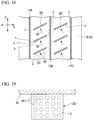
Fig. 18 is a view corresponding toFig. 3 , showing swirl breakers of a fourth embodiment; -
Fig. 19 is a view showing a swirl flow collision surface, which is a front view of the swirl breaker of the fourth embodiment; -
Fig. 20 is a perspective view of a swirl breaker of a fifth embodiment; -
Fig. 21 is a perspective view of a variant of the swirl breaker of the fifth embodiment; -
Fig. 22 is a view of the swirl breaker of the fifth embodiment when seen from the outside in the radial direction; -
Fig. 23 is a view corresponding toFig. 7 , showing swirls breaker of a sixth embodiment; -
Fig. 24 is a view corresponding toFig. 7 , showing a variant of the swirl breakers of the sixth embodiment; and -
Fig. 25 is a view corresponding toFig. 7 , showing a variant of the swirl breakers of the sixth embodiment. - Hereinafter, a steam turbine serving as a rotating machine of a first embodiment of the present invention will be described based on the accompanying drawings.
- As shown in
Fig. 1 , a steam turbine 1 of the embodiment includes acasing 10,adjustment valves 20 configured to adjust an amount and a pressure of steam S introduced into thecasing 10, arotor 30 rotatably installed inside thecasing 10 and configured to transmit power to a machine such as a generator (not shown) or the like,stator blades 40 held by thecasing 10,rotor blades 50 installed at therotor 30, and abearing unit 60 configured to support therotor 30 such that therotor 30 is rotatable about an axis thereof. - The
casing 10 has an internal space, which is hermetically sealed, and serves as a flow path of the steam S. A ring-shaped partition plate outer wheel (a stationary annular body) 11 through which therotor 30 is inserted is strongly fixed to an inner wall surface of thecasing 10. - The plurality of
adjustment valves 20 are attached to the inside of thecasing 10. The plurality ofadjustment valves 20 each include anadjustment valve chamber 21 into which the steam S is introduced from a boiler (not shown), avalve body 22 and avalve seat 23. When thevalve body 22 is separated from thevalve seat 23, a steam flow path is opened, and the steam S is introduced into an internal space of thecasing 10 via asteam chamber 24. - The
rotor 30 includes a rotormain body 31, and a plurality ofdisks 32 extending from an outer circumference of the rotormain body 31 in a radial direction of the rotor 30 (hereinafter, simply referred to as a radial direction). Therotor 30 is configured to transmit rotational energy to a machine such as a generator (not shown) or the like. - The bearing
unit 60 includes ajournal bearing device 61 and athrust bearing device 62, and rotatably supports therotor 30. - The
stator blades 40 constitute annular stator blade groups in which a plurality of the blades extend from thecasing 10 toward the inner circumferential side, are radially disposed to surround therotor 30, and are held at the above-mentioned partition plateouter wheel 11. Inner sides in the radial direction of thestator blades 40 are connected to a ring-shaped partition plateinner wheel 14 or the like through which therotor 30 is inserted. - Six annular stator blade groups constituted by the plurality of
stator blades 40 are formed in an axial direction of the rotor 30 (hereinafter, simply referred to as an axial direction) at intervals, and pressure energy of the steam S is converted into velocity energy to be introduced into therotor blades 50 immediately downstream. - The
rotor blades 50 are strongly attached to an outer circumferential section of thedisk 32 included in therotor 30, and the plurality of annular rotor blade groups, which are radially disposed, are provided downstream from the annular stator blade groups. - These annular stator blade groups and annular rotor blade groups are disposed in pairs at each stage. That is, the steam turbine 1 is constituted in six stages. Among the stages, tip sections of the
rotor blades 50 in the final stage are referred to asshrouds 51 configured to connect tip sections of rotor blades neighboring in a circumferential direction of the rotor 30 (hereinafter, simply referred to as a circumferential direction). - As shown in
Fig. 2 , an annular groove 12 (a cavity) having a diameter that increases from an inner circumferential section of the partition plateouter wheel 11 and using an inner circumferential surface of thecasing 10 as abottom section 13 is formed downstream in the axial direction of the partition plateouter wheel 11. Theshrouds 51 are accommodated in theannular groove 12, and thebottom section 13 is opposite to outercircumferential surfaces 52 of theshrouds 51 via a gap Gd in the radial direction. - Three sealing fins 17 (17A to 17C) extending toward the
shrouds 51 in the radial direction are formed at thebottom section 13. The sealing fins 17 (17A to 17C) extend from thebottom section 13 toward the outercircumferential surfaces 52 of theshrouds 51 at the inner circumferential side, and extend in the circumferential direction. The sealing fins 17 (17A to 17C) are configured to form micro gaps m with the outercircumferential surfaces 52 of theshrouds 51 in the radial direction. - A dimension of the micro gaps m is set within a range in which the sealing fins 17 (17A to 17C) do not come in contact with the
rotor blades 50 in consideration of a heat growth amount of thecasing 10 or therotor blades 50, a centrifugal growth amount of therotor blades 50, or the like. - A plurality of
swirl breakers 2 are disposed between the sealingfins 17 neighboring in the axial direction at predetermined intervals in the circumferential direction. Theswirl breakers 2 are disposed in the circumferential direction at equal intervals. Specifically, theswirl breakers 2 are plate-shaped bodies disposed between the sealingfin 17A and the sealingfin 17B and extending inward in the radial direction to protrude from the inner circumferential surface (the bottom section 13) of theannular groove 12 of thecasing 10. - As shown in
Fig. 3 , surfaces of theswirl breakers 2 are swirlflow collision surfaces 3 with which a swirl flow collides. The swirlflow collision surfaces 3 are disposed in the axial direction, and are directed toward one side in the circumferential direction (designated by reference character C). - In addition, gaps n serving as swirl flow transmission parts are formed between the
swirl breakers 2 and the sealingfins 17 disposed at a first side (upstream) in the axial direction of theswirl breakers 2 and a second side (downstream) in the axial direction opposite to the first side. That is, theswirl breakers 2 are not connected to the sealingfins 17 in the axial direction. The dimension of the gaps n will be described below. - Here, an operation of the steam turbine 1 with this configuration will be described.
- First, when the adjustment valves 20 (see
Fig. 1 ) are in an open state, the steam S is introduced into the internal space of thecasing 10 from the boiler (not shown). - The steam S introduced into the internal space of the
casing 10 sequentially passes the annular stator blade group and the annular rotor blade group of each stage. - In the annular stator blade group of each stage, a velocity component in the circumferential direction of the steam S is increased while passing the
stator blades 40. A majority of the steam SM out of the steam S is introduced between therotor blades 50, and energy of the steam SM is converted into rotational energy to apply a rotational force to therotor 30. - In addition, a portion of the steam SL (for example, about several %) out of the steam S is discharged from the
stator blades 40, and then a component in the circumferential direction is increased, i.e., a swirl flow is introduced into theannular groove 12. - Here, behavior of the leaked steam SL introduced into the
annular groove 12 when theswirl breakers 2 are not disposed will be described. - As shown in
Fig. 4 , a portion of the leaked steam SL becomes a leak jet LJ having a velocity in the axial direction calculated with a function of a size of a pressure difference between the upstream side and the downstream side of the sealingfin 17A to flow toward the sealingfins 17B neighboring in the axial direction while going over the sealingfin 17A. - In addition, as shown in
Fig. 5 , the leaked steam SL flows as a swirl flow having a component Vc in the circumferential direction into a fin space F surrounded by the sealingfin 17A and the sealingfin 17B in front and rear thereof. That is, the swirl flow has a strong component Vc in the circumferential direction at an outlet of thestator blades 40, and a velocity of the component Vc in the circumferential direction is larger than a velocity component Vx in the axial direction. - The swirl flow has a vortex shape (see
Figs. 4 and5 ) in which a rotational center axis is in the circumferential direction due to viscosity of the leak jet LJ passing through the sealingfins 17. In addition, a flow in the vicinity of the leak jet LJ has a flow pattern as shown inFig. 6 . - Next, behavior of the leaked steam SL when the
swirl breakers 2 are installed will be described. - As shown in
Fig. 7 , when a swirl flow of the leaked steam SL is introduced in a vortex shape between the two sealingfins 17 neighboring in the axial direction while going over the sealingfin 17A of the upstream side in the axial direction (designated by reference character S1), and the swirl bounces off the sealingfin 17B of the downstream side in the axial direction (designated by reference character S2). The bouncing swirl flow S2 collides with the swirlflow collision surface 3 of theswirl breaker 2 after bouncing off the sealingfin 17A of the upstream side in the axial direction. Accordingly, the swirl flow S2 is reduced. - In addition, the swirl flow S2 passes through the gaps n between the
swirl breakers 2 and the sealingfins 17. That is, the swirl flow S2 escapes to the other side in the circumferential direction while a flow thereof is not completely blocked by theswirl breakers 2. Here, the gaps n between theswirl breaker 2 and the sealingfins 17 are appropriately adjusted according to an area of theswirl breaker 2 required to reduce the swirl flow S2 colliding with the swirl flow S2, and an amount of the swirl flow S2 to pass through the gaps n. - According to the embodiment, as the
swirl breakers 2 are disposed between the sealingfins 17, the swirl flow collides with theswirl breakers 2. Accordingly, as a dynamic pressure of the swirl flow is attenuated by theswirl breakers 2, a tangential velocity component included in the steam SL can be reduced. - In addition, as the gaps n are formed between the
swirl breakers 2 and the sealingfins 17, the swirl flow easily passes through the gaps n, and a reduction effect of the swirl flow is increased. - In addition, as the swirl
flow collision surfaces 3 of theswirl breakers 2 are disposed perpendicular to a flow direction of the swirl flow, the swirl flow can be more effectively reduced. - In addition, as the gaps n between the
swirl breakers 2 and the sealingfins 17 serve as the swirl flow transmission parts, the swirl flow transmission parts can be formed with a simpler configuration. - Further, in the
swirl breakers 2, when the swirl flow introduced from one side in the circumferential direction can be released to the other side in the circumferential direction, angles and positions in the axial direction of theswirl breakers 2 may be different from the above-mentioned embodiment. That is, configurations of theswirl breakers 2 and the gaps n can be appropriately adjusted according to the behavior of the swirl flow. - For example, as shown in
Fig. 8 , the swirlflow collision surfaces 3 of theswirl breakers 2 may be disposed to be inclined with respect to the axial direction (designated by reference character X). Angles of the swirlflow collision surfaces 3 with respect to the axial direction are appropriately adjusted according to the behavior of the swirl flow S2. Specifically, the swirlflow collision surfaces 3 are adjusted to be perpendicular to the flow direction of the swirl flow S2. - Further, the
swirl breakers 2 may not be continuously formed. For example, as shown inFig. 9 , slits 54 in the radial direction may be formed at centers in an extension direction in the axial direction of theswirl breakers 2. - In addition, as shown in
Fig. 10 ,swirl breakers 2a of a first side in the axial direction andswirl breakers 2b of a second side in the axial direction may be configured to be alternately disposed in the circumferential direction. - In addition, the gaps n are preferably formed between the
swirl breakers 2 and the sealing fin of the downstream side (the sealingfin 17B ofFig. 7 ) so that the swirl flow S2 can arrive at the vicinity of thecasing 10 throughout the circumferential direction and then collide with theswirl breakers 2 of a downstream side in a swirl direction. - For example, as shown in
Fig. 11 , only one sides in the axial direction of theswirl breakers 2 may be configured to be connected to the sealingfins 17. That is, the gaps n may be configured to be formed only at the second sides in the axial direction of theswirl breakers 2. - Further, as shown in
Fig. 12 , theswirl breakers 2 having one side in the axial direction connected to the sealingfins 17 and theswirl breakers 2 having the second sides in the axial direction connected to the sealingfins 17 may be configured to be alternately disposed in the circumferential direction. - Hereinafter, a rotating machine of a second embodiment of the present invention will be described based on the accompanying drawings. Further, the embodiment will be described focusing on differences from the above-mentioned first embodiment, and description of the same parts will be omitted.
- As shown in
Figs. 13 and 14 ,swirl breakers 2B of the rotating machine of the embodiment are configured such that inclination of the swirlflow collision surface 3 is different at a proximal end side (an outer circumferential side in the radial direction) and a tip side (an inner circumferential side in the radial direction) of theswirl breakers 2B. - Specifically, the
swirl breakers 2B are constituted byproximal end sections 5 andtip sections 6, and theproximal end sections 5 and thetip sections 6 are connected to be twisted. Theproximal end sections 5 have main surfaces inclined in the axial direction to be perpendicular to the flow direction of the swirl flow S2 that bounces off the sealingfin 17B of the downstream side. Thetip sections 6 have angles adjusted to attenuate effectively the tangential velocity component of the swirl flow S2 that bounces off the sealingfin 17A of the upstream side. - According to the embodiment, the swirl breakers that are more appropriate for the behavior of the swirl flow S2 that repeatedly bounces between the sealing
fin 17A of the upstream side and the sealingfin 17B of the downstream side can be provided. - Hereinafter, a rotating machine of a third embodiment of the present invention will be described based on the accompanying drawings. Further, the embodiment will be described focusing on differences from the above-mentioned first embodiment, and description of the same parts will be omitted.
- As shown in
Fig. 15 ,swirl breakers 2C of the embodiment are formed of plate-shaped porous bodies having a plurality ofholes 9, and both ends in the axial direction are connected to the sealingfins 17. That is, the plurality ofholes 9 serve as the swirl flow transmission parts. - According to the embodiment, as the
swirl breakers 2C and the sealingfins 17 are connected, stiffness of the sealing apparatus can be increased. - Further, a diameter, a shape, the number, disposition, and so on, of the
holes 9 can be appropriately varied. For example, as shown inFig. 16 ,single holes 9A may be disposed at substantially centers of theswirl breakers 2C. In addition, as shown inFig. 17 , singlerectangular holes 9B may be disposed at substantially centers of theswirl breakers 2C. In this way, as the configuration of the holes is varied, the swirl breakers that are more appropriate for the behavior of the swirl flow can be provided. - Hereinafter, a rotating machine of a fourth embodiment of the present invention will be described based on the accompanying drawings.
- As shown in
Figs. 18 and 19 , dimple processing (concavo-convex processing like a surface of a golf ball) is performed on swirlflow collision surfaces 3 ofswirl breakers 2D and surfaces of the sealingfins 17 of the embodiment. That is, a plurality of regularly arrangedconcave sections 55 are formed on the swirlflow collision surfaces 3 and the surfaces of the sealingfins 17. - The
concave sections 55 may be hemispherical concave sections or may be conical concave sections. Alternatively, theconcave sections 55 may be pyramidal concave sections such as a hexagonal pyramids or the like. In addition, the dimple processing may be performed on either theswirl collision surfaces 3 or the sealingfins 17, and need not be performed on both the swirlflow collision surfaces 3 and the surfaces of the sealingfins 17. - According to the embodiment, in comparison with the case in which the
swirl collision surfaces 3 and the sealingfins 17 are planar, since energy loss due to friction of the swirl flow with theswirl breakers 2D and the sealingfins 17 is increased, a reduction effect of the tangential velocity component included in the steam SL is increased. - Hereinafter, a rotating machine of a fifth embodiment of the present invention will be described based on the accompanying drawings.
- As shown in
Fig. 20 , aswirl breaker 2E of the embodiment has a cross-sectional shape having a wave form when seen from a direction along aconnection side 56 to a bottom surface 13 (seeFig. 2 ). In other words, theswirl breaker 2E of the embodiment is formed in a wave form that is continuously curved in one direction perpendicular to the main surface and an opposite direction thereof from a proximal end side (an outer circumferential side in the radial direction designated by reference character R) and a tip side (an inner circumferential side in the radial direction R). The wave form may be a rectangular wave pattern or a sine wave pattern. - In addition, as the
swirl breaker 2E is formed in a wave form, a depth of a chamfer 57 (a concave line) parallel to theconnection side 56 formed at theswirl collision surface 3 may become deeper downstream (as shown by an arrow S2E). - According to the embodiment, in addition to separated flows MV1 and MV2 having vorticity in the radial direction R formed by the
swirl breakers 2 from the first embodiment to the fourth embodiment, a plurality of small-scaled vortices SV having vorticity in an axial direction X/a circumferential direction C are generated. Accordingly, disturbance of a flow in a space between the sealing fins 17 (seeFig. 2 ) is amplified, and a reduction effect of the tangential velocity component included in the steam SL is increased. - Further, as shown in
Fig. 21 , theswirl breaker 2E may be formed in a convex or concave arc shape toward the swirl flow S2 when seen in a direction from the proximal end side (the outer circumferential side in the radial direction R) toward the tip side (the inner circumferential side in the radial direction R). That is, the swirlflow collision surface 3 may be formed in a curved shape. - In addition, as shown in
Fig. 22 , in theswirl breaker 2E, the proximal end section 5 (an outer circumferential side in the radial direction, the connection side 56) may have a concave arc shape toward the swirl flow S2, and the tip section 6 (an inner circumferential side in the radial direction) may have a convex arc shape toward the swirl flow S2. Theproximal end section 5 and thetip section 6 may be smoothly connected to form a three-dimensional twisted shape. - Hereinafter, a rotating machine of a sixth embodiment of the present invention will be described based on the accompanying drawings.
- As shown in
Fig. 23 ,swirl breakers 2F of the embodiment have shapes in which a width is reduced from the proximal end sections 5 (the outer circumferential sides in the radial direction) toward the tip sections 6 (the inner circumferential sides in the radial direction). Specifically, the swirlflow collision surfaces 3 of theswirl breakers 2F have trapezoidal shapes in which the longer bases are connected to the casing and the shorter bases are disposed at theshroud 51 side. - According to the embodiment, the leak jet LJ that passes through the sealing
fins 17 can be easily introduced into the space surrounded by the sealingfins 17 at which theswirl breakers 2F are installed, and an effect of theswirl breakers 2F can be further increased. - Further, the
swirl breakers 2F of the embodiment are not limited to the shapes shown inFig. 23 . For example, as shown in a variant ofFig. 24 , the surfaces may have stepped shapes in which halves of theproximal end section 5 sides have the same width as theswirl breakers 2 of the first embodiment and halves of thetip section 6 sides have smaller widths than the halves of the proximal end sides. - In addition, as shown in a variant of
Fig. 25 , trapezoidal shapes in which sides 58 facing theupstream sealing fins 17 are parallel to the sealingfins 17 may be used. - Further, the technical scope of the present invention is not limited to the above-mentioned embodiments but various modifications may be made. In addition, the above-mentioned features described in the plurality of embodiments may be arbitrarily combined.
- For example, the swirl breakers are not limited to planar shapes but may have curved plate shapes.
- In addition, while the outer
circumferential surfaces 52 of theshrouds 51 of the embodiments have a planar shape, the swirl breakers of the present invention may also be applied to shrouds having steps formed at the outer circumferential surfaces 52. -
- 1 steam turbine
- 2 swirl breaker
- 3 swirl flow collision surface
- 5 proximal end section
- 6 tip section
- 9, 9A, 9B hole (swirl flow transmission part)
- 10 casing
- 11 partition plate outer wheel
- 12 annular groove (cavity)
- 13 bottom section
- 14 partition plate inner wheel
- 17, 17A, 17B, 17C sealing fin
- 20 adjustment valve
- 21 adjustment valve chamber
- 22 valve body
- 23 valve seat
- 30 rotor
- 31 rotor main body
- 32 disk
- 40 stator blade
- 50 rotor blade
- 51 shroud
- 52 outer circumferential surface
- 54 slit
- 55 concave section
- 60 bearing unit
- 61 journal bearing device
- 62 thrust bearing device
- m micro gap
- n gap (swirl flow transmission part)
- F fin space
- Gd gap
- LJ leak jet
- S1, S2 swirl flow
- S, SL, SM steam
Claims (10)
- A rotating machine (1) such as a steam turbine, a gas turbine, or the like, comprising:a rotor (30) having a rotor main body that rotates about an axis thereof, and a rotor blade (50) disposed to extend from the rotor main body outward in a radial direction;a casing (10) disposed to surround the rotor (30) from an outer circumferential side and having a cavity (12) that a tip of the rotor blade (50) enters;
a plurality of sealing fins (17A, 17B, 17C) extending from an inner circumferential surface of the cavity (12) of the casing (10) toward the tip of the rotor blade (50) and configured to seal a space between the casing (10) and the rotor blade (50); andswirl breakers (2) disposed between the plurality of sealing fins (17A, 17B, 17C), extending from the inner circumferential surface of the cavity (12) of the casing (10) inward in the radial direction, and having swirl flow collision surfaces (3) with which a swirl flow collides and swirl flow transmission parts formed at at least parts of the swirl flow collision surfaces (3) and through which the swirl flow passes in a circumferential direction,characterized in that the swirl breakers (2) are formed of a plate-shaped body and in between the sealing fin at an upstream side (17A, 17B) and the sealing fin at a downstream side (17B, 17C), and the swirl flow collision surfaces (3) are formed to have different angles with respect to the axial direction at a proximal end side and a tip side, andthe swirl flow transmission parts (n) are gaps formed between the swirl flow collision surfaces (3) and at least one of the sealing fins (17A, 17B, 17C) of one side in an axial direction and another of the sealing fins (17A, 17B, 17C) of the other side in the axial direction. - The rotating machine according to claim 1, wherein the swirl breakers are formed of a plate-shaped body having at least one hole, and the swirl flow transmission parts are the at least one hole.
- The rotating machine according to any one of claims 1 or 2, wherein dimple processing is performed on at least one of the swirl flow collision surfaces of the swirl breakers and the surfaces of the sealing fins.
- The rotating machine according to any one of claims 1 to 3, wherein the swirl breakers have a cross-sectional shape having a wave form.
- The rotating machine according to any one of claims 1 to 4, wherein the swirl breakers are formed to have a width that reduces toward the inner circumferential side in the radial direction.
- A rotating machine (1) such as a steam turbine, a gas turbine, or the like, comprising:a rotor (30) having a rotor main body that rotates about an axis thereof, and a rotor blade (50) disposed to extend from the rotor main body outward in a radial direction;a casing (10) disposed to surround the rotor (50) from an outer circumferential side and having a cavity (12) that a tip of the rotor blade (50) enters;a plurality of sealing fins (17A,17B,17C) extending from an inner circumferential surface of the cavity (12) of the casing (10) toward the tip of the rotor blade (50) and configured to seal a space between the casing (10) and the rotor blade (50); andswirl breakers (2) disposed between the plurality of sealing fins (17A,17B,17C), extending from the inner circumferential surface of the cavity (12) of the casing (10) inward in the radial direction, and having swirl flow collision surfaces (3) with which a swirl flow collides and swirl flow transmission parts (n) formed at least parts of the swirl flow collision surfaces (3) and through which the swirl flow passes in a circumferential direction,characterized in that the swirl breakers (2) are formed in between the sealing fin at an upstream side (17A, 17B) and the sealing fin at a downstream side (17B, 17C), the swirl flow collision surfaces (3) are formed to be inclined with respect to the axial direction to be perpendicular to a flow direction of the swirl flow, andthe swirl flow transmission parts (n) are gaps formed between the swirl flow collision surfaces (3) and at least one of the sealing fins (17A, 17B, 17C) of one side in an axial direction and another of the sealing fins (17A, 17B, 17C) of the other side in the axial direction.
- The rotating machine according to claim 6, wherein the swirl breakers are formed of a plate-shaped body having at least one hole, and the swirl flow transmission parts are the at least one hole.
- The rotating machine according to claims 6 or 7, wherein dimple processing is performed on at least one of the swirl flow collision surfaces of the swirl breakers and the surfaces of the sealing fins.
- The rotating machine according to any one of claims 6 to 8, wherein the swirl breakers have a cross-sectional shape having a wave form.
- The rotating machine according to any one of claims 6 to 9, wherein the swirl breakers are formed to have a width that reduces toward the inner circumferential side in the radial direction.
Applications Claiming Priority (2)
| Application Number | Priority Date | Filing Date | Title |
|---|---|---|---|
| JP2013078029 | 2013-04-03 | ||
| PCT/JP2014/052095 WO2014162767A1 (en) | 2013-04-03 | 2014-01-30 | Rotating machine |
Publications (3)
| Publication Number | Publication Date |
|---|---|
| EP2982832A1 EP2982832A1 (en) | 2016-02-10 |
| EP2982832A4 EP2982832A4 (en) | 2016-12-21 |
| EP2982832B1 true EP2982832B1 (en) | 2018-12-26 |
Family
ID=51658072
Family Applications (1)
| Application Number | Title | Priority Date | Filing Date |
|---|---|---|---|
| EP14779746.8A Not-in-force EP2982832B1 (en) | 2013-04-03 | 2014-01-30 | Rotating machine |
Country Status (6)
| Country | Link |
|---|---|
| US (1) | US10247025B2 (en) |
| EP (1) | EP2982832B1 (en) |
| JP (1) | JP5951890B2 (en) |
| KR (1) | KR101660204B1 (en) |
| CN (1) | CN105074134B (en) |
| WO (1) | WO2014162767A1 (en) |
Families Citing this family (13)
| Publication number | Priority date | Publication date | Assignee | Title |
|---|---|---|---|---|
| GB201519869D0 (en) * | 2015-11-11 | 2015-12-23 | Rolls Royce Plc | Shrouded turbine blade |
| JP6662661B2 (en) * | 2016-02-29 | 2020-03-11 | 三菱日立パワーシステムズ株式会社 | Seal structure and turbo machinery |
| JP6712873B2 (en) * | 2016-02-29 | 2020-06-24 | 三菱日立パワーシステムズ株式会社 | Seal structure and turbo machine |
| EP3312388B1 (en) * | 2016-10-24 | 2019-06-05 | MTU Aero Engines GmbH | Rotor part, corresponding compressor, turbine and manufacturing method |
| JP6783257B2 (en) * | 2018-01-31 | 2020-11-11 | 三菱重工業株式会社 | Axial rotating machine |
| JP6846374B2 (en) * | 2018-03-08 | 2021-03-24 | 三菱重工業株式会社 | Moving wing side sealing device, stationary wing side sealing device and rotating machine |
| JP6916755B2 (en) | 2018-03-09 | 2021-08-11 | 三菱重工業株式会社 | Rotating machine |
| JP7029317B2 (en) | 2018-03-09 | 2022-03-03 | 三菱重工業株式会社 | Rotating machine |
| FR3082879B1 (en) * | 2018-06-20 | 2020-07-03 | Safran Aircraft Engines | LABYRINTH SEAL FOR AN AIRCRAFT TURBOMACHINE |
| JP7267022B2 (en) | 2019-01-31 | 2023-05-01 | 三菱重工業株式会社 | rotating machinery |
| JP7145774B2 (en) * | 2019-01-31 | 2022-10-03 | 三菱重工業株式会社 | rotating machinery |
| JP7370226B2 (en) | 2019-11-19 | 2023-10-27 | 三菱重工業株式会社 | steam turbine |
| CN114320487A (en) * | 2022-01-07 | 2022-04-12 | 中国航发贵阳发动机设计研究所 | Grate tooth sealing structure and method suitable for same |
Family Cites Families (42)
| Publication number | Priority date | Publication date | Assignee | Title |
|---|---|---|---|---|
| US3092393A (en) * | 1958-01-20 | 1963-06-04 | Rolls Royce | Labyrinth seals |
| US3572728A (en) * | 1968-06-17 | 1971-03-30 | Gen Eelctric Co | Rotary seal |
| US3694882A (en) * | 1970-09-24 | 1972-10-03 | Westinghouse Electric Corp | Method for providing a corrugated seal in an elastic fluid machine |
| US4370094A (en) * | 1974-03-21 | 1983-01-25 | Maschinenfabrik Augsburg-Nurnberg Aktiengesellschaft | Method of and device for avoiding rotor instability to enhance dynamic power limit of turbines and compressors |
| DE2413655C3 (en) * | 1974-03-21 | 1978-05-03 | Maschinenfabrik Augsburg-Nuernberg Ag, 8500 Nuernberg | Device for dynamic stabilization of the rotor of a gas or steam turbine |
| US4273510A (en) * | 1974-03-21 | 1981-06-16 | Maschinenfabrik Augsburg-Nunberg Aktiengesellschaft | Method of and device for avoiding rotor instability to enhance dynamic power limit of turbines and compressors |
| GB1519590A (en) * | 1974-11-11 | 1978-08-02 | Rolls Royce | Gas turbine engine |
| IT1063035B (en) * | 1975-05-09 | 1985-02-11 | Maschf Augsburg Nuernberg Ag | APPARATUS FOR REALIZING THE PROCEDURE TO ELEVATE THE DYNAMIC POWER LIMIT OF STEAM OR GAS TURBINES OR COMPRESSORS |
| JPS54103910A (en) * | 1978-02-01 | 1979-08-15 | Hitachi Ltd | Seal structure for tips of moving vanes of axial-flow machine |
| JPS5923601B2 (en) | 1982-03-26 | 1984-06-04 | 松下電器産業株式会社 | decorative lighting stands |
| JPS58165201U (en) * | 1982-04-30 | 1983-11-02 | 三菱重工業株式会社 | Turbine blade seal structure |
| US4420161A (en) * | 1982-05-10 | 1983-12-13 | General Electric Company | Rotor stabilizing labyrinth seals for steam turbines |
| JPS6052306A (en) | 1983-08-31 | 1985-03-25 | 松下電工株式会社 | Manufacture of aggregate veneer |
| JPS6052306U (en) * | 1983-09-05 | 1985-04-12 | 三菱重工業株式会社 | Labyrinth seal for turbo machinery |
| DE3505491A1 (en) * | 1985-02-16 | 1986-08-21 | MTU Motoren- und Turbinen-Union München GmbH, 8000 München | GASKET FOR A FLUID MACHINE |
| JPS62116101A (en) | 1985-11-15 | 1987-05-27 | 日本製紙株式会社 | Method of treating woody material |
| JPS62116101U (en) * | 1986-01-17 | 1987-07-23 | ||
| US4876505A (en) * | 1988-05-27 | 1989-10-24 | Westinghouse Electric Corp. | Apparatus and method for monitoring steam turbine shroud clearance |
| WO1994016251A1 (en) * | 1993-01-08 | 1994-07-21 | The Texas A&M University System | Pressure damper seals |
| US5707064A (en) * | 1993-01-08 | 1998-01-13 | The Texas A&M University System | Modulated pressure damper seal |
| JPH081264A (en) | 1994-06-10 | 1996-01-09 | Hitachi Ltd | Production of rotary heat transfer fin |
| US5439347A (en) * | 1994-08-31 | 1995-08-08 | Brandon; Ronald E. | Turbine tip seal damage protection means |
| US5632598A (en) * | 1995-01-17 | 1997-05-27 | Dresser-Rand | Shrouded axial flow turbo machine utilizing multiple labrinth seals |
| US6155778A (en) * | 1998-12-30 | 2000-12-05 | General Electric Company | Recessed turbine shroud |
| US6368054B1 (en) * | 1999-12-14 | 2002-04-09 | Pratt & Whitney Canada Corp. | Split ring for tip clearance control |
| US6402464B1 (en) * | 2000-08-29 | 2002-06-11 | General Electric Company | Enhanced heat transfer surface for cast-in-bump-covered cooling surfaces and methods of enhancing heat transfer |
| US6632069B1 (en) * | 2001-10-02 | 2003-10-14 | Oleg Naljotov | Step of pressure of the steam and gas turbine with universal belt |
| WO2004113770A2 (en) * | 2003-06-20 | 2004-12-29 | Elliott Company | Swirl-reversal abradable labyrinth seal |
| EP1515000B1 (en) * | 2003-09-09 | 2016-03-09 | Alstom Technology Ltd | Blading of a turbomachine with contoured shrouds |
| US7004475B2 (en) | 2003-09-26 | 2006-02-28 | Siemens Westinghouse Power Corporation | Flow dam design for labyrinth seals to promote rotor stability |
| JP2006104952A (en) | 2004-09-30 | 2006-04-20 | Toshiba Corp | Swirling flow preventive device of fluid machine |
| US20070009349A1 (en) * | 2005-07-11 | 2007-01-11 | General Electric Company | Impingement box for gas turbine shroud |
| JP2007120476A (en) | 2005-10-31 | 2007-05-17 | Toshiba Corp | Swirl flow prevention device for fluid machine |
| US7686568B2 (en) | 2006-09-22 | 2010-03-30 | General Electric Company | Methods and apparatus for fabricating turbine engines |
| JP2008184974A (en) | 2007-01-30 | 2008-08-14 | Toshiba Corp | Seal device for fluid machine and steam turbine |
| US7988410B1 (en) * | 2007-11-19 | 2011-08-02 | Florida Turbine Technologies, Inc. | Blade tip shroud with circular grooves |
| JP2010077882A (en) | 2008-09-25 | 2010-04-08 | Toyota Motor Corp | Labyrinth seal structure for multistage turbine |
| JP5517530B2 (en) * | 2009-09-03 | 2014-06-11 | 三菱重工業株式会社 | Turbine |
| JP2012007594A (en) * | 2010-06-28 | 2012-01-12 | Mitsubishi Heavy Ind Ltd | Seal device, and fluid machine provided with the same |
| US20130017072A1 (en) | 2011-07-14 | 2013-01-17 | General Electric Company | Pattern-abradable/abrasive coatings for steam turbine stationary component surfaces |
| US20130230379A1 (en) * | 2012-03-01 | 2013-09-05 | General Electric Company | Rotating turbomachine component having a tip leakage flow guide |
| JP5567077B2 (en) * | 2012-08-23 | 2014-08-06 | 三菱重工業株式会社 | Rotating machine |
-
2014
- 2014-01-30 US US14/780,111 patent/US10247025B2/en not_active Expired - Fee Related
- 2014-01-30 CN CN201480017939.7A patent/CN105074134B/en not_active Expired - Fee Related
- 2014-01-30 JP JP2015509933A patent/JP5951890B2/en not_active Expired - Fee Related
- 2014-01-30 KR KR1020157022298A patent/KR101660204B1/en active IP Right Grant
- 2014-01-30 EP EP14779746.8A patent/EP2982832B1/en not_active Not-in-force
- 2014-01-30 WO PCT/JP2014/052095 patent/WO2014162767A1/en active Application Filing
Non-Patent Citations (1)
| Title |
|---|
| None * |
Also Published As
| Publication number | Publication date |
|---|---|
| CN105074134B (en) | 2017-06-20 |
| EP2982832A1 (en) | 2016-02-10 |
| WO2014162767A1 (en) | 2014-10-09 |
| JPWO2014162767A1 (en) | 2017-02-16 |
| CN105074134A (en) | 2015-11-18 |
| US10247025B2 (en) | 2019-04-02 |
| KR101660204B1 (en) | 2016-09-26 |
| EP2982832A4 (en) | 2016-12-21 |
| KR20150114964A (en) | 2015-10-13 |
| JP5951890B2 (en) | 2016-07-13 |
| US20160047265A1 (en) | 2016-02-18 |
Similar Documents
| Publication | Publication Date | Title |
|---|---|---|
| EP2982832B1 (en) | Rotating machine | |
| JP6131177B2 (en) | Seal structure and rotating machine | |
| US20120121411A1 (en) | Labyrinth Seals for Turbomachinery | |
| US10316679B2 (en) | Seal structure and rotating machine | |
| KR101464850B1 (en) | Turbine | |
| EP2096262A1 (en) | Axial flow turbine with low shroud leakage losses | |
| EP2878771B1 (en) | Axial flow fluid machine | |
| EP2578810B1 (en) | Seal structure, turbine machine equipped with same, and power plant equipped with said turbine machine | |
| JP2010159667A (en) | Axial flow turbine | |
| KR20100102211A (en) | Gas turbin and disc and method for forming radial passage of disc | |
| WO2012052740A1 (en) | Sealing device for reducing fluid leakage in turbine apparatus | |
| KR101939520B1 (en) | turbine | |
| JP5517530B2 (en) | Turbine | |
| JP2014141912A (en) | Rotary machine | |
| KR102050186B1 (en) | Seal pin, seal structure and turbo machine | |
| JP2014141955A (en) | Rotary machine | |
| JP6209787B2 (en) | Seal structure and rotating machine | |
| KR101946184B1 (en) | Rotary machine | |
| JP6930896B2 (en) | Turbines and blades | |
| JP2010275957A (en) | Turbine | |
| JP6763538B2 (en) | Rotating machine | |
| JP2020139464A (en) | Axial flow turbine |
Legal Events
| Date | Code | Title | Description |
|---|---|---|---|
| PUAI | Public reference made under article 153(3) epc to a published international application that has entered the european phase |
Free format text: ORIGINAL CODE: 0009012 |
|
| 17P | Request for examination filed |
Effective date: 20150925 |
|
| AK | Designated contracting states |
Kind code of ref document: A1 Designated state(s): AL AT BE BG CH CY CZ DE DK EE ES FI FR GB GR HR HU IE IS IT LI LT LU LV MC MK MT NL NO PL PT RO RS SE SI SK SM TR |
|
| AX | Request for extension of the european patent |
Extension state: BA ME |
|
| DAX | Request for extension of the european patent (deleted) | ||
| A4 | Supplementary search report drawn up and despatched |
Effective date: 20161122 |
|
| RIC1 | Information provided on ipc code assigned before grant |
Ipc: F01D 5/22 20060101ALI20161116BHEP Ipc: F01D 5/02 20060101ALI20161116BHEP Ipc: F01D 11/08 20060101AFI20161116BHEP Ipc: F02C 7/28 20060101ALI20161116BHEP Ipc: F01D 25/24 20060101ALI20161116BHEP |
|
| GRAP | Despatch of communication of intention to grant a patent |
Free format text: ORIGINAL CODE: EPIDOSNIGR1 |
|
| RIC1 | Information provided on ipc code assigned before grant |
Ipc: F01D 11/08 20060101AFI20180621BHEP Ipc: F01D 5/02 20060101ALI20180621BHEP Ipc: F01D 25/24 20060101ALI20180621BHEP Ipc: F02C 7/28 20060101ALI20180621BHEP Ipc: F01D 5/22 20060101ALI20180621BHEP |
|
| STAA | Information on the status of an ep patent application or granted ep patent |
Free format text: STATUS: GRANT OF PATENT IS INTENDED |
|
| INTG | Intention to grant announced |
Effective date: 20180726 |
|
| GRAS | Grant fee paid |
Free format text: ORIGINAL CODE: EPIDOSNIGR3 |
|
| GRAA | (expected) grant |
Free format text: ORIGINAL CODE: 0009210 |
|
| STAA | Information on the status of an ep patent application or granted ep patent |
Free format text: STATUS: THE PATENT HAS BEEN GRANTED |
|
| AK | Designated contracting states |
Kind code of ref document: B1 Designated state(s): AL AT BE BG CH CY CZ DE DK EE ES FI FR GB GR HR HU IE IS IT LI LT LU LV MC MK MT NL NO PL PT RO RS SE SI SK SM TR |
|
| REG | Reference to a national code |
Ref country code: GB Ref legal event code: FG4D |
|
| REG | Reference to a national code |
Ref country code: CH Ref legal event code: EP |
|
| REG | Reference to a national code |
Ref country code: AT Ref legal event code: REF Ref document number: 1081705 Country of ref document: AT Kind code of ref document: T Effective date: 20190115 |
|
| REG | Reference to a national code |
Ref country code: DE Ref legal event code: R096 Ref document number: 602014038701 Country of ref document: DE |
|
| REG | Reference to a national code |
Ref country code: IE Ref legal event code: FG4D |
|
| PG25 | Lapsed in a contracting state [announced via postgrant information from national office to epo] |
Ref country code: BG Free format text: LAPSE BECAUSE OF FAILURE TO SUBMIT A TRANSLATION OF THE DESCRIPTION OR TO PAY THE FEE WITHIN THE PRESCRIBED TIME-LIMIT Effective date: 20190326 Ref country code: FI Free format text: LAPSE BECAUSE OF FAILURE TO SUBMIT A TRANSLATION OF THE DESCRIPTION OR TO PAY THE FEE WITHIN THE PRESCRIBED TIME-LIMIT Effective date: 20181226 Ref country code: LT Free format text: LAPSE BECAUSE OF FAILURE TO SUBMIT A TRANSLATION OF THE DESCRIPTION OR TO PAY THE FEE WITHIN THE PRESCRIBED TIME-LIMIT Effective date: 20181226 Ref country code: NO Free format text: LAPSE BECAUSE OF FAILURE TO SUBMIT A TRANSLATION OF THE DESCRIPTION OR TO PAY THE FEE WITHIN THE PRESCRIBED TIME-LIMIT Effective date: 20190326 Ref country code: HR Free format text: LAPSE BECAUSE OF FAILURE TO SUBMIT A TRANSLATION OF THE DESCRIPTION OR TO PAY THE FEE WITHIN THE PRESCRIBED TIME-LIMIT Effective date: 20181226 Ref country code: LV Free format text: LAPSE BECAUSE OF FAILURE TO SUBMIT A TRANSLATION OF THE DESCRIPTION OR TO PAY THE FEE WITHIN THE PRESCRIBED TIME-LIMIT Effective date: 20181226 |
|
| REG | Reference to a national code |
Ref country code: NL Ref legal event code: MP Effective date: 20181226 |
|
| REG | Reference to a national code |
Ref country code: LT Ref legal event code: MG4D |
|
| PG25 | Lapsed in a contracting state [announced via postgrant information from national office to epo] |
Ref country code: AL Free format text: LAPSE BECAUSE OF FAILURE TO SUBMIT A TRANSLATION OF THE DESCRIPTION OR TO PAY THE FEE WITHIN THE PRESCRIBED TIME-LIMIT Effective date: 20181226 Ref country code: SE Free format text: LAPSE BECAUSE OF FAILURE TO SUBMIT A TRANSLATION OF THE DESCRIPTION OR TO PAY THE FEE WITHIN THE PRESCRIBED TIME-LIMIT Effective date: 20181226 Ref country code: RS Free format text: LAPSE BECAUSE OF FAILURE TO SUBMIT A TRANSLATION OF THE DESCRIPTION OR TO PAY THE FEE WITHIN THE PRESCRIBED TIME-LIMIT Effective date: 20181226 Ref country code: GR Free format text: LAPSE BECAUSE OF FAILURE TO SUBMIT A TRANSLATION OF THE DESCRIPTION OR TO PAY THE FEE WITHIN THE PRESCRIBED TIME-LIMIT Effective date: 20190327 |
|
| REG | Reference to a national code |
Ref country code: AT Ref legal event code: MK05 Ref document number: 1081705 Country of ref document: AT Kind code of ref document: T Effective date: 20181226 |
|
| PG25 | Lapsed in a contracting state [announced via postgrant information from national office to epo] |
Ref country code: NL Free format text: LAPSE BECAUSE OF FAILURE TO SUBMIT A TRANSLATION OF THE DESCRIPTION OR TO PAY THE FEE WITHIN THE PRESCRIBED TIME-LIMIT Effective date: 20181226 |
|
| PG25 | Lapsed in a contracting state [announced via postgrant information from national office to epo] |
Ref country code: PL Free format text: LAPSE BECAUSE OF FAILURE TO SUBMIT A TRANSLATION OF THE DESCRIPTION OR TO PAY THE FEE WITHIN THE PRESCRIBED TIME-LIMIT Effective date: 20181226 Ref country code: ES Free format text: LAPSE BECAUSE OF FAILURE TO SUBMIT A TRANSLATION OF THE DESCRIPTION OR TO PAY THE FEE WITHIN THE PRESCRIBED TIME-LIMIT Effective date: 20181226 Ref country code: IT Free format text: LAPSE BECAUSE OF FAILURE TO SUBMIT A TRANSLATION OF THE DESCRIPTION OR TO PAY THE FEE WITHIN THE PRESCRIBED TIME-LIMIT Effective date: 20181226 Ref country code: CZ Free format text: LAPSE BECAUSE OF FAILURE TO SUBMIT A TRANSLATION OF THE DESCRIPTION OR TO PAY THE FEE WITHIN THE PRESCRIBED TIME-LIMIT Effective date: 20181226 Ref country code: PT Free format text: LAPSE BECAUSE OF FAILURE TO SUBMIT A TRANSLATION OF THE DESCRIPTION OR TO PAY THE FEE WITHIN THE PRESCRIBED TIME-LIMIT Effective date: 20190426 |
|
| PG25 | Lapsed in a contracting state [announced via postgrant information from national office to epo] |
Ref country code: EE Free format text: LAPSE BECAUSE OF FAILURE TO SUBMIT A TRANSLATION OF THE DESCRIPTION OR TO PAY THE FEE WITHIN THE PRESCRIBED TIME-LIMIT Effective date: 20181226 Ref country code: RO Free format text: LAPSE BECAUSE OF FAILURE TO SUBMIT A TRANSLATION OF THE DESCRIPTION OR TO PAY THE FEE WITHIN THE PRESCRIBED TIME-LIMIT Effective date: 20181226 Ref country code: IS Free format text: LAPSE BECAUSE OF FAILURE TO SUBMIT A TRANSLATION OF THE DESCRIPTION OR TO PAY THE FEE WITHIN THE PRESCRIBED TIME-LIMIT Effective date: 20190426 Ref country code: SM Free format text: LAPSE BECAUSE OF FAILURE TO SUBMIT A TRANSLATION OF THE DESCRIPTION OR TO PAY THE FEE WITHIN THE PRESCRIBED TIME-LIMIT Effective date: 20181226 Ref country code: SK Free format text: LAPSE BECAUSE OF FAILURE TO SUBMIT A TRANSLATION OF THE DESCRIPTION OR TO PAY THE FEE WITHIN THE PRESCRIBED TIME-LIMIT Effective date: 20181226 |
|
| REG | Reference to a national code |
Ref country code: CH Ref legal event code: PL |
|
| REG | Reference to a national code |
Ref country code: DE Ref legal event code: R097 Ref document number: 602014038701 Country of ref document: DE |
|
| PG25 | Lapsed in a contracting state [announced via postgrant information from national office to epo] |
Ref country code: LU Free format text: LAPSE BECAUSE OF NON-PAYMENT OF DUE FEES Effective date: 20190130 |
|
| REG | Reference to a national code |
Ref country code: BE Ref legal event code: MM Effective date: 20190131 |
|
| REG | Reference to a national code |
Ref country code: IE Ref legal event code: MM4A |
|
| PG25 | Lapsed in a contracting state [announced via postgrant information from national office to epo] |
Ref country code: AT Free format text: LAPSE BECAUSE OF FAILURE TO SUBMIT A TRANSLATION OF THE DESCRIPTION OR TO PAY THE FEE WITHIN THE PRESCRIBED TIME-LIMIT Effective date: 20181226 Ref country code: MC Free format text: LAPSE BECAUSE OF FAILURE TO SUBMIT A TRANSLATION OF THE DESCRIPTION OR TO PAY THE FEE WITHIN THE PRESCRIBED TIME-LIMIT Effective date: 20181226 Ref country code: DK Free format text: LAPSE BECAUSE OF FAILURE TO SUBMIT A TRANSLATION OF THE DESCRIPTION OR TO PAY THE FEE WITHIN THE PRESCRIBED TIME-LIMIT Effective date: 20181226 |
|
| PLBE | No opposition filed within time limit |
Free format text: ORIGINAL CODE: 0009261 |
|
| STAA | Information on the status of an ep patent application or granted ep patent |
Free format text: STATUS: NO OPPOSITION FILED WITHIN TIME LIMIT |
|
| GBPC | Gb: european patent ceased through non-payment of renewal fee |
Effective date: 20190326 |
|
| PG25 | Lapsed in a contracting state [announced via postgrant information from national office to epo] |
Ref country code: BE Free format text: LAPSE BECAUSE OF NON-PAYMENT OF DUE FEES Effective date: 20190131 |
|
| 26N | No opposition filed |
Effective date: 20190927 |
|
| PG25 | Lapsed in a contracting state [announced via postgrant information from national office to epo] |
Ref country code: CH Free format text: LAPSE BECAUSE OF NON-PAYMENT OF DUE FEES Effective date: 20190131 Ref country code: LI Free format text: LAPSE BECAUSE OF NON-PAYMENT OF DUE FEES Effective date: 20190131 |
|
| PG25 | Lapsed in a contracting state [announced via postgrant information from national office to epo] |
Ref country code: GB Free format text: LAPSE BECAUSE OF NON-PAYMENT OF DUE FEES Effective date: 20190326 Ref country code: IE Free format text: LAPSE BECAUSE OF NON-PAYMENT OF DUE FEES Effective date: 20190130 |
|
| PG25 | Lapsed in a contracting state [announced via postgrant information from national office to epo] |
Ref country code: FR Free format text: LAPSE BECAUSE OF NON-PAYMENT OF DUE FEES Effective date: 20190226 Ref country code: SI Free format text: LAPSE BECAUSE OF FAILURE TO SUBMIT A TRANSLATION OF THE DESCRIPTION OR TO PAY THE FEE WITHIN THE PRESCRIBED TIME-LIMIT Effective date: 20181226 |
|
| PG25 | Lapsed in a contracting state [announced via postgrant information from national office to epo] |
Ref country code: TR Free format text: LAPSE BECAUSE OF FAILURE TO SUBMIT A TRANSLATION OF THE DESCRIPTION OR TO PAY THE FEE WITHIN THE PRESCRIBED TIME-LIMIT Effective date: 20181226 |
|
| PG25 | Lapsed in a contracting state [announced via postgrant information from national office to epo] |
Ref country code: MT Free format text: LAPSE BECAUSE OF NON-PAYMENT OF DUE FEES Effective date: 20190130 |
|
| PG25 | Lapsed in a contracting state [announced via postgrant information from national office to epo] |
Ref country code: CY Free format text: LAPSE BECAUSE OF FAILURE TO SUBMIT A TRANSLATION OF THE DESCRIPTION OR TO PAY THE FEE WITHIN THE PRESCRIBED TIME-LIMIT Effective date: 20181226 |
|
| PGFP | Annual fee paid to national office [announced via postgrant information from national office to epo] |
Ref country code: DE Payment date: 20210119 Year of fee payment: 8 |
|
| PG25 | Lapsed in a contracting state [announced via postgrant information from national office to epo] |
Ref country code: HU Free format text: LAPSE BECAUSE OF FAILURE TO SUBMIT A TRANSLATION OF THE DESCRIPTION OR TO PAY THE FEE WITHIN THE PRESCRIBED TIME-LIMIT; INVALID AB INITIO Effective date: 20140130 |
|
| PG25 | Lapsed in a contracting state [announced via postgrant information from national office to epo] |
Ref country code: MK Free format text: LAPSE BECAUSE OF FAILURE TO SUBMIT A TRANSLATION OF THE DESCRIPTION OR TO PAY THE FEE WITHIN THE PRESCRIBED TIME-LIMIT Effective date: 20181226 |
|
| REG | Reference to a national code |
Ref country code: DE Ref legal event code: R119 Ref document number: 602014038701 Country of ref document: DE |
|
| PG25 | Lapsed in a contracting state [announced via postgrant information from national office to epo] |
Ref country code: DE Free format text: LAPSE BECAUSE OF NON-PAYMENT OF DUE FEES Effective date: 20220802 |