EP2578810B1 - Seal structure, turbine machine equipped with same, and power plant equipped with said turbine machine - Google Patents
Seal structure, turbine machine equipped with same, and power plant equipped with said turbine machine Download PDFInfo
- Publication number
- EP2578810B1 EP2578810B1 EP11786598.0A EP11786598A EP2578810B1 EP 2578810 B1 EP2578810 B1 EP 2578810B1 EP 11786598 A EP11786598 A EP 11786598A EP 2578810 B1 EP2578810 B1 EP 2578810B1
- Authority
- EP
- European Patent Office
- Prior art keywords
- shrouds
- main flow
- fluid
- downstream side
- rotating shaft
- Prior art date
- Legal status (The legal status is an assumption and is not a legal conclusion. Google has not performed a legal analysis and makes no representation as to the accuracy of the status listed.)
- Active
Links
- 239000012530 fluid Substances 0.000 claims description 109
- 238000007789 sealing Methods 0.000 claims description 33
- 239000007789 gas Substances 0.000 description 95
- 238000011144 upstream manufacturing Methods 0.000 description 5
- 230000004048 modification Effects 0.000 description 3
- 238000012986 modification Methods 0.000 description 3
- 230000000694 effects Effects 0.000 description 2
- 239000000567 combustion gas Substances 0.000 description 1
- 230000003247 decreasing effect Effects 0.000 description 1
Images


Classifications
-
- F—MECHANICAL ENGINEERING; LIGHTING; HEATING; WEAPONS; BLASTING
- F01—MACHINES OR ENGINES IN GENERAL; ENGINE PLANTS IN GENERAL; STEAM ENGINES
- F01D—NON-POSITIVE DISPLACEMENT MACHINES OR ENGINES, e.g. STEAM TURBINES
- F01D5/00—Blades; Blade-carrying members; Heating, heat-insulating, cooling or antivibration means on the blades or the members
- F01D5/12—Blades
- F01D5/14—Form or construction
- F01D5/141—Shape, i.e. outer, aerodynamic form
- F01D5/142—Shape, i.e. outer, aerodynamic form of the blades of successive rotor or stator blade-rows
- F01D5/143—Contour of the outer or inner working fluid flow path wall, i.e. shroud or hub contour
-
- F—MECHANICAL ENGINEERING; LIGHTING; HEATING; WEAPONS; BLASTING
- F01—MACHINES OR ENGINES IN GENERAL; ENGINE PLANTS IN GENERAL; STEAM ENGINES
- F01D—NON-POSITIVE DISPLACEMENT MACHINES OR ENGINES, e.g. STEAM TURBINES
- F01D11/00—Preventing or minimising internal leakage of working-fluid, e.g. between stages
- F01D11/08—Preventing or minimising internal leakage of working-fluid, e.g. between stages for sealing space between rotor blade tips and stator
-
- F—MECHANICAL ENGINEERING; LIGHTING; HEATING; WEAPONS; BLASTING
- F01—MACHINES OR ENGINES IN GENERAL; ENGINE PLANTS IN GENERAL; STEAM ENGINES
- F01D—NON-POSITIVE DISPLACEMENT MACHINES OR ENGINES, e.g. STEAM TURBINES
- F01D11/00—Preventing or minimising internal leakage of working-fluid, e.g. between stages
- F01D11/005—Sealing means between non relatively rotating elements
-
- F—MECHANICAL ENGINEERING; LIGHTING; HEATING; WEAPONS; BLASTING
- F01—MACHINES OR ENGINES IN GENERAL; ENGINE PLANTS IN GENERAL; STEAM ENGINES
- F01D—NON-POSITIVE DISPLACEMENT MACHINES OR ENGINES, e.g. STEAM TURBINES
- F01D11/00—Preventing or minimising internal leakage of working-fluid, e.g. between stages
- F01D11/02—Preventing or minimising internal leakage of working-fluid, e.g. between stages by non-contact sealings, e.g. of labyrinth type
-
- F—MECHANICAL ENGINEERING; LIGHTING; HEATING; WEAPONS; BLASTING
- F01—MACHINES OR ENGINES IN GENERAL; ENGINE PLANTS IN GENERAL; STEAM ENGINES
- F01D—NON-POSITIVE DISPLACEMENT MACHINES OR ENGINES, e.g. STEAM TURBINES
- F01D25/00—Component parts, details, or accessories, not provided for in, or of interest apart from, other groups
- F01D25/24—Casings; Casing parts, e.g. diaphragms, casing fastenings
-
- F—MECHANICAL ENGINEERING; LIGHTING; HEATING; WEAPONS; BLASTING
- F01—MACHINES OR ENGINES IN GENERAL; ENGINE PLANTS IN GENERAL; STEAM ENGINES
- F01D—NON-POSITIVE DISPLACEMENT MACHINES OR ENGINES, e.g. STEAM TURBINES
- F01D5/00—Blades; Blade-carrying members; Heating, heat-insulating, cooling or antivibration means on the blades or the members
- F01D5/12—Blades
- F01D5/22—Blade-to-blade connections, e.g. for damping vibrations
- F01D5/225—Blade-to-blade connections, e.g. for damping vibrations by shrouding
-
- F—MECHANICAL ENGINEERING; LIGHTING; HEATING; WEAPONS; BLASTING
- F02—COMBUSTION ENGINES; HOT-GAS OR COMBUSTION-PRODUCT ENGINE PLANTS
- F02C—GAS-TURBINE PLANTS; AIR INTAKES FOR JET-PROPULSION PLANTS; CONTROLLING FUEL SUPPLY IN AIR-BREATHING JET-PROPULSION PLANTS
- F02C7/00—Features, components parts, details or accessories, not provided for in, or of interest apart form groups F02C1/00 - F02C6/00; Air intakes for jet-propulsion plants
- F02C7/28—Arrangement of seals
Definitions
- the present invention relates to a seal structure, a turbine machine having the same, and a power generating plant equipped with the same, and more specifically, it relates to fluid leaking out between a sealing part and shrouds at tips of stationary blades.
- a plurality of moving blades 51 of a turbine are provided with moving blade shrouds 53 at tips thereof so as to face a turbine casing 52.
- the moving blade shrouds 53 come into contact with adjacent shrouds and form an annular shape during rotation of the moving blades 51.
- a seal portion in which seal fins 54 extending from the turbine casing 52 toward the moving blade shrouds 53 are connected to the turbine casing 52.
- the seal fins 54 are provided to reduce the level of leakage of fluid, which is a main flow of fluid guided to the moving blades 51 and leaking out between the moving blade shrouds 53 and the turbine casing 52 (hereinbelow, "leakage jet") (for example, JP 2005-214051 A and JP 2006-138259 A concerning a steam turbine).
- the leakage jet collides with the downstream-side wall 52a of the turbine casing 52
- the leakage jet after collision, moves radially inward along the downstream-side wall 52a of the turbine casing 52.
- the leakage jet having moved radially inward along the wall 52a of the turbine casing 52 traps a portion of the main flow of fluid and generates an eddy in the space 55, as indicated by dashed lines in FIG. 5 . Because a portion of the main flow of fluid is trapped in the space 55, the flow of the main flow of fluid is greatly disturbed, resulting in a problem in that mixing loss (mixing loss) occurs.
- EP 2096262 A discloses a seal structure for shrouds of rotary blades of an axial flow turbine.
- the seal structure includes a turbine casing and a blade ring having shrouds formed at outer tip end portions of rotary blades and spaced apart from the casing to form a radial tip clearance through which a leakage flow is passing during operation of the turbine.
- the casing comprises plural sealing elements arranged in the radial gap facing the shrouds to reduce the shroud leakage flow.
- a deflector is provided at the casing downstream in the vicinity of the shroud step and extending in a radial direction towards the inward of the casing such that the deflector is still spaced in the radial direction from the outer radius level of the shroud step.
- JP 57-8302 A and JP 2007-321721 A disclose further similar seal structures for shrouds of rotary blades of an axial flow turbine.
- the present invention has been made in view of these circumstances, and an object thereof is to provide a seal structure capable of suppressing disturbance of a flow of a main flow of fluid due to fluid leaking out of a seal portion of stationary blades, a turbine machine having the same, and a power generating plant equipped with the same.
- the present invention provides the seal structure with the features of claim 1, the turbine machine having the same, and the power generating plant equipped with the same.
- the seal structure according to the present invention includes shrouds that are provided at tips of a plurality of stationary blades on which a main flow of fluid impinges in operation and that come into contact with adjacent shrouds to form a cylindrical shape; a sealing part connected to a rotating shaft (structure body) facing the shrouds; wherein the outer circumference of the rotating shaft is formed in a recessed shape that is recessed towards the central axis of the rotating shaft and a space that is defined by downstream sides of the shrouds, a downstream side of the sealing part, a wall surface of the recessed shape facing the radially inner side of the shrouds, and a wall of said recessed shape on a downstream side of the stationary blades on a downstream side of the rotating shaft and that communicates with the main flow of fluid that has impinged on the blades.
- a corner of the wall on the downstream side of the rotating shaft is formed so as to be disposed a predetermined distance away from a shroud extension extending toward the downstream side of the shrouds and away from a sealing-part extension provided substantially parallel to the shroud extension and extending toward the downstream side of the sealing part and so as to be located on an opposite side of the shroud extension with respect to the sealing-part extension.
- the leakage fluid that has collided with the wall of the structure body flows along the downstream-side wall of the structure body in the direction opposite to the structure body, i.e., toward the main flow of fluid. Because the space communicates with the main flow of fluid that has impinged on the blades, the fluid leaking out along the wall joins the main flow of fluid that has impinged on the blades at a large angle (for example, 90°). Thus, the flow of the main flow of fluid that has impinged on the blades is greatly disturbed.
- the fluid leaking out into the space 55 collides with the downstream-side wall 52a of the turbine casing 52, and the leakage fluid after collision moves radially inward along the downstream-side wall 52a of the turbine casing 52 and flows clockwise, as indicated by dashed lines in FIG. 5 .
- the leakage fluid flows in a direction opposite to the flow direction of the main flow of fluid that has impinged on the moving blades 51, trapping the main flow of fluid that has impinged on the moving blades 51 in the space 55. Accordingly, the flow of the main flow of fluid that has impinged on the moving blades 51 is greatly disturbed.
- the fluid leaking out into a space 65 collides with a downstream-side wall 62a of the rotating shaft 62, and a portion of the leakage fluid after collision moves radially outward along the downstream-side wall 62a of the rotating shaft 62 and flows counterclockwise, as indicated by dashed lines in FIG. 6 .
- the leakage fluid flows in a direction opposite to the flow direction of the main flow of fluid that has impinged on the stationary blades 61, trapping the main flow of fluid that has impinged on the stationary blades 61 in the space 65. Accordingly, the flow of the main flow of fluid that has impinged on the stationary blades 61 is greatly disturbed.
- an end of the downstream-side wall of the rotating shaft defining the space is disposed away from the shroud extension extending toward the downstream side of the shroud and away from the sealing-part extension extending parallel thereto toward the downstream side of the sealing part and is located on the opposite side of the shroud extension with respect to the sealing-part extension.
- the leakage fluid can be led out at a position away from the end of the downstream-side wall (wall surface) of the rotating shaft, it is possible to prevent the fluid leaking out between the sealing part and the shrouds from colliding with the downstream-side wall of the rotating shaft.
- the predetermined distance between the shroud extension and the sealing-part extension is a radial distance set such that the sealing part does not touch the shrouds during operation and such that the level of leakage of fluid leaking between the shrouds and the sealing part can be reduced to a minimum.
- surfaces of the shrouds facing the structure body are preferably provided substantially parallel to a flow direction of the main flow of fluid that has impinged on the blades.
- the surfaces of the shrouds facing the structure body i.e., the inner circumferential surfaces in the case of the stationary blades
- the surfaces of the shrouds facing the structure body are provided substantially parallel to the flow direction of the main flow of fluid that has impinged on the blades.
- surfaces of the shrouds facing the structure body are preferably inclined such that they gradually become farther away from the structure body along a flow direction of the main flow of fluid that has impinged on the blades.
- the surfaces of the shrouds facing the structure body are provided in an inclined manner such that they gradually become farther away from the structure body along the flow direction of the main flow of fluid that has impinged on the blades.
- the angle at which the surfaces of the shrouds facing the structure body are inclined is set such that the leakage fluid does not greatly disturb the flow of the main flow of fluid that has impinged on the blades when it joins the main flow of fluid that has impinged on the blades.
- the preferred angle at which the leakage fluid is made to join the main flow of fluid that has impinged on the blades is 30° or less.
- surfaces of the shrouds facing the structure body are preferably inclined such that they gradually become closer to the structure body along a flow direction of the main flow of fluid that has impinged on the blades.
- the surfaces of the shrouds facing the structure body are provided in an inclined manner such that they gradually become closer to the structure body along the flow direction of the main flow of fluid that has impinged on the blades.
- the angle at which the surfaces of the shrouds facing the structure body are inclined is set such that the leakage fluid does not greatly disturb the flow of the main flow of fluid that has impinged on the blades when it joins the main flow of fluid that has impinged on the blades.
- the preferred angle at which the leakage fluid is made to join the main flow of fluid that has impinged on the blades is 30° or less.
- a turbine machine according to the present invention includes any one of the above-described seal structures.
- a seal structure capable of reducing mixing loss caused when the leakage jet leaking out between the sealing part and the shrouds joins the main flow of fluid that has impinged on the blades is provided. This can prevent a drop in the turbine efficiency of the turbine machine.
- a power generating plant according to the present invention includes the above-described turbine machine.
- the turbine machine capable of preventing a drop in the turbine efficiency is provided. This can prevent a drop in the power generating efficiency of the power generating plant.
- An end of the downstream-side wall of the structure body defining the space is disposed away from the shroud extension extending toward the downstream side of the shroud and away from the sealing-part extension extending parallel thereto toward the downstream side of the sealing part and is located on the opposite side of the shroud extension with respect to the sealing-part extension.
- the leakage fluid can be led out at a position away from the end of the downstream-side wall (wall surface) of the structure body, it is possible to prevent the fluid leaking out between the sealing part and the shrouds from colliding with the downstream-side wall of the structure body.
- FIG. 1 shows a seal structure of a gas turbine (a turbine machine) of a power generating plant according to a first example serving to explain features of the invention, in which (A) is a schematic view of the configuration thereof and (B) is a partial enlarged view thereof.
- a gas turbine installed in a power generating plant includes stationary blades (not shown) that direct a flow of a main flow of gas (main flow of fluid), which is combustion gas that has been guided into the gas turbine, to a plurality of moving blades (blades) 2, the moving blades 2 on which the main flow of gas that has passed through the stationary blades impinges, moving blade shrouds 3 (3a) that are provided at tips of the moving blades 2 and come into contact with adjacent shrouds to form a cylindrical shape, and a turbine casing (structure body) 4 enclosing the moving blades 2 and the moving blade shrouds (shrouds) 3a therein.
- the turbine casing 4 has a cylindrical shape surrounding the outer circumferences of the moving blade shrouds 3a provided at the tips of the moving blades 2.
- the inner circumference of the turbine casing 4 is formed in a recessed shape that is recessed toward the outer circumference of the turbine casing 4.
- the recessed shape provided in the inner circumference of the turbine casing 4 is defined by a wall surface (wall) 4a on the upstream side of the moving blades 2, a wall surface 4b on the downstream side of the moving blades 2, and a wall surface 4c connecting the wall surface 4a and the wall surface 4b and located facing the radially outer side of the moving blade shrouds 3a.
- the recessed shape provided in the inner circumference of the turbine casing 4 is recessed toward the outer circumference of the turbine casing 4.
- the seal fins 5 are connected, at base ends, to the wall surface 4c forming the recessed shape provided in the inner circumference of the turbine casing 4.
- the seal fins 5 include at least one seal fin, for example, three seal fins.
- the seal fins 5a, 5b, and 5c extend from the wall surface 4c of the turbine casing 4 radially inward toward the moving blade shrouds 3a.
- the tips of the seal fins 5a, 5b, and 5c extending toward the moving blade shrouds 3a are disposed a predetermined distance away from surfaces of the moving blade shrouds 3a facing the turbine casing 4 (hereinbelow, "outer circumferential surfaces").
- the number of seal fins 5 is not limited to three, but may be one, two, four or more.
- seal fins 5a, 5b, and 5c reduce the level of leakage of gas (leakage fluid) leaking out between the moving blades 2 and the turbine casing 4 and leaking out between the moving blade shrouds 3a and the turbine casing 4 toward the downstream side of the moving blades 2.
- the predetermined distance between the outer circumferential surfaces of the moving blade shrouds 3a and the tips of the seal fins 5a, 5b, and 5c in the radial direction is a radial distance that is small but not so small that the outer circumferential surfaces of the moving blade shrouds 3a mechanically touch the seal fins 5a, 5b, and 5c during operation and such that the level of leakage of gas leaking out between the moving blades 2 and the turbine casing 4 (hereinbelow, "leakage jet”) can be reduced to a minimum.
- the plurality of moving blades 2 are provided in the circumferential direction of a rotating shaft (not shown).
- the plurality of moving blades 2 constitute moving blade rows 6.
- the moving blade rows 6 and stationary blade rows (not shown), in which stationary blades are provided in the circumferential direction of the rotating shaft, are provided alternately in multiple stages in the axial direction.
- the main flow of gas impinges on the moving blades 2.
- the gas turbine is rotationally driven.
- the main flow of gas that has impinged on the moving blades 2 is guided to the stationary blade rows provided on the downstream side.
- a cavity (space) 7 is defined by downstream portions of the moving blade shrouds 3a, a downstream portion of the seal fin 5c (sealing part in the present invention) located on the most downstream side among the seal fins 5, and the wall surfaces 4b and 4c of the turbine casing 4 on the downstream side of the recessed shape, and communicates with the main flow of gas that has impinged on the moving blades 2. As shown in FIG.
- a corner (end) 4d, on the inner circumference side, of the wall surface 4b of the turbine casing 4 forming the cavity 7 is disposed away from a moving-blade-shroud extension (shroud extension) 11 extending along the outer circumferential surfaces of the moving blade shrouds 3a toward the downstream side of the moving blade shrouds 3a and away from a seal-fin extension (sealing-part extension) 10 provided substantially parallel thereto at a predetermined distance and extending toward the downstream side of the seal fin 5c located on the most downstream side via the tip of the seal fin 5c located on the most downstream side, and is located on the opposite side of the moving-blade-shroud extension 11 with respect to the seal-fin extension 10.
- the predetermined distance between the moving-blade-shroud extension 11 and the seal-fin extension 10 is a radial distance set such that the seal fins 5a, 5b, and 5c do not touch the moving blade shrouds 3a during operation and such that the level of leakage of the leakage jet leaking out between the moving blade shrouds 3a and the seal fins 5a, 5b, and 5c can be reduced to a minimum.
- the moving blade shrouds 3a are provided at the tips of the moving blades 2.
- the moving blade shrouds 3a come into contact with adjacent shrouds and form a cylindrical shape.
- the outer circumferential surfaces of the moving blade shrouds 3a have a stepped shape having steps arranged in the flow direction of the main flow of gas impinging on the moving blades 2.
- the moving blade shrouds 3a have, at the middle parts thereof in the flow direction of the main flow of gas, projections protruding toward the turbine casing 4 (outer circumferential side).
- the outer circumferential surfaces of the moving blade shrouds 3a on the upstream side, at the middle part, and on the downstream side are formed substantially parallel to the flow direction of the main flow of gas after impinging on the moving blades 2.
- the shape of the moving blade shrouds 3a is not limited to a stepped shape, but may be another shape.
- the main flow of gas that has been guided to the gas turbine is guided from the stationary blade rows to the moving blade rows 6.
- the main flow of gas that has been guided to the moving blade rows 6 impinges on the moving blades 2 and drives the gas turbine.
- the main flow of gas after impinging on the moving blades 2 is guided to the stationary blade rows provided on the downstream side.
- a portion of the main flow of gas impinging on the moving blades 2 leaks out from the upstream side of the moving blades 2 to a space between the moving blade shrouds 3a and the turbine casing 4.
- the main flow of gas leaking out to the space between the moving blade shrouds 3a and the turbine casing 4 is led out from between the moving blade shrouds 3a and the seal fin 5c on the most downstream side, becoming a leakage jet.
- the leakage jet led out from between the moving blade shrouds 3a and the seal fin 5c on the most downstream side is led out to an area between the seal-fin extension 10 and the moving-blade-shroud extension 11 (hereinbelow, a "leakage-jet flowing area").
- the corner 4d of the wall surface 4b on the downstream side of the turbine casing 4 is disposed away from the moving-blade-shroud extension 11 and from the seal-fin extension 10 and is located on the opposite side of the moving-blade-shroud extension 11 with respect to the seal-fin extension 10, the leakage jet led out of the leakage-jet flowing area is led out toward the main flow of gas without colliding with the wall surface 4b or the corner 4d on the downstream side of the turbine casing 4.
- the leakage jet led out of the leakage-jet flowing area joins the main flow of gas that has impinged on the moving blades 2 at a small inflow angle with respect to the flow direction thereof.
- the preferred inflow angle is 30° or less, but a smaller inflow angle is more preferable.
- an angle closer to parallel to the flow direction of the main flow of gas is more preferable, and an angle parallel to the flow direction of the main flow of gas is the most preferable.
- the leakage jet can be led out at a position away from the wall surface 4b and the corner 4d on the downstream side of the turbine casing 4, it is possible to prevent the leakage jet leaking out between the seal fin 5c located on the most downstream side and the moving blade shrouds 3a from colliding with the wall surface 4b on the downstream side of the turbine casing 4. Accordingly, it is possible to suppress a situation where the leakage jet collides with the wall surface 4b on the downstream side of the turbine casing 4, the leakage jet, after collision, moves radially inward along the wall surface 4b on the downstream side of the turbine casing 4, forming an eddy flowing clockwise, as indicated by dashed lines in FIG.
- the seal structure, the turbine machine having the same, and the power generating plant equipped with the same described above provide the following advantages.
- the corner (end) 4d of the wall surface (wall) 4b on the downstream side of the turbine casing (structure body) 4 forming the cavity (space) 7 is disposed away from the moving-blade-shroud extension (shroud extension) 11 extending toward the downstream side of the moving blade shrouds (shrouds) 3a and away from the seal-fin extension (sealing-part extension) 10 extending parallel thereto toward the downstream side of the seal fin (sealing part) 5c located on the most downstream side, and is located on the opposite side of the moving-blade-shroud extension 11 with respect to the seal-fin extension 10.
- the leakage jet (leakage fluid) leaking out between the seal fin 5c located on the most downstream side and the moving blade shrouds 3a from colliding with the wall surface 4b on the downstream side of the turbine casing 4.
- the leakage jet can join the main flow of gas (main flow of fluid) that has impinged on the moving blades (blades) 2 at a small inflow angle. Accordingly, mixing loss caused by the leakage jet joining the main flow of gas can be reduced.
- the leakage jet can be led out at a position away from the wall surface 4b on the downstream side of the turbine casing 4, it is possible to prevent the leakage jet leaking out between the seal fin 5c located on the most downstream side and the moving blade shrouds 3a from colliding with the wall surface 4b on the downstream side of the turbine casing 4. Accordingly, it is possible to suppress a situation where the leakage jet collides with the wall surface 4b on the downstream side of the turbine casing 4, the leakage jet, after collision, moves radially inward along the wall surface 4b on the downstream side of the turbine casing 4, forming an eddy flowing clockwise, as indicated by dashed lines in FIG.
- the leakage jet flows counterclockwise, as indicated by dashed lines in FIG. 1(A) , in the cavity 7. Accordingly, because the flow direction of the leakage jet when joining the main flow of gas that has impinged on the moving blades 2 is substantially the same as that of the main flow of gas, the flow of the main flow of gas that has impinged on the moving blades 2 is prevented from being greatly disturbed. Thus, mixing loss caused by the leakage jet joining the flow of the main flow of gas can be reduced.
- the surfaces (outer circumferential surfaces) of the moving blade shrouds 3a facing the turbine casing 4 are provided substantially parallel to the flow direction of the main flow of gas that has impinged on the moving blades 2.
- the leakage jet leaking out between the seal fin 5c located on the most downstream side and the moving blade shrouds 3a can be made to join the main flow of gas that has impinged on the moving blades 2 at a small inflow angle. Accordingly, mixing loss caused by the leakage jet joining the main flow of gas can be reduced.
- a seal structure capable of reducing mixing loss caused when the leakage jet leaking out between the seal fin 5c located on the most downstream side and the moving blade shrouds 3a joins the main flow of gas that has impinged on the moving blades 2 is provided. This can prevent a drop in the turbine efficiency of the gas turbine (turbine machine).
- a gas turbine capable of preventing a drop in the turbine efficiency is provided. This can prevent a drop in the power generating efficiency of the power generating plant.
- FIG. 2 shows a seal structure of a gas turbine in a power generating plant according to a second example serving to explain features of the present invention, in which (A) is a schematic view of the configuration thereof and (B) is a partial enlarged view thereof.
- the outer circumferential surfaces on the downstream side of moving blade shrouds (shrouds) 3b are inclined from projections provided at the middle parts of the moving blade shrouds 3b such that they gradually become farther away from the inside of the turbine casing (structure body) 4 along the flow direction of the main flow of gas (main flow) that has impinged on the moving blades (blades) 2.
- the rate at which the outer circumferential surfaces on the downstream side of the moving blade shrouds 3b gradually become farther away from the inside of the turbine casing 4, i.e., the inclination angle, is desirably 30° or less with respect to the flow direction of the main flow of gas that has impinged on the moving blades 2, which is an inflow angle that does not greatly disturb the flow of the main flow of gas when the leakage jet (leakage fluid) joins the main flow of gas that has impinged on the moving blades 2.
- the leakage jet led out from between the seal fin 5c located on the most downstream side and the moving blade shrouds 3b is led out toward the main flow of gas without colliding with the wall surface (wall) 4b or the corner (end) 4d of the turbine casing 4.
- the leakage jet led out from between the seal fin 5c located on the most downstream side and the moving blade shrouds 3b joins the main flow of gas that has impinged on the moving blades 2 at a small inflow angle with respect to the flow direction thereof.
- the seal structure, the turbine machine having the same, and the power generating plant equipped with the same according to this example provide the following advantages.
- the outer circumferential surfaces on the downstream side of the moving blade shrouds (shrouds) 3b are inclined such that they gradually become farther away from the turbine casing (structure body) 4 along the flow direction of the main flow of gas (main flow of fluid) that has impinged on the moving blades (blades) 2.
- the leakage jet (leakage fluid) can be led out at a position away from the wall surface (wall) 4b on the downstream side of the turbine casing 4, and thus, it is possible to prevent the leakage jet leaking out between the seal fin (sealing part) 5c located on the most downstream side and the moving blade shrouds 3b from colliding with the wall surface 4b on the downstream side of the turbine casing 4.
- the leakage jet collides with the wall surface 4b on the downstream side of the turbine casing 4, and the leakage jet, after collision, moves radially inward along the wall surface 4b on the downstream side of the turbine casing 4, forming a clockwise eddy in the cavity 7(space), as indicated by dashed lines in FIG. 5 , and trapping the main flow of gas that has impinged on the moving blades 2 in the cavity 7. That is, the leakage jet flows counterclockwise in the cavity 7, as indicated by dashed lines in FIG. 2(A) . Accordingly, it is possible to prevent the flow of the main flow of gas that has impinged on the moving blades 2 from being greatly disturbed and to reduce mixing loss caused by the leakage jet joining the main flow of gas.
- a third example serving to explain features of the inventionof the present invention will be described below.
- a seal structure, a turbine machine having the same, and a power generating plant equipped with the same according to this example differ from those according to the first example in that the outer circumferential surfaces on the downstream side of the moving blade shrouds disposed a predetermined distance away from the seal fin (sealing part) 5c located on the most downstream side gradually become closer to the inside of the turbine casing in the flow direction of the main flow of gas that has impinged on the moving blades, the other configurations are the same. Accordingly, the same configurations and the same flow will be denoted by the same reference numerals, and descriptions thereof will be omitted.
- FIG. 3 shows a seal structure of a gas turbine in a power generating plant according to a third example serving to explain features of the present invention, in which (A) is a schematic view of the configuration thereof and (B) is a partial enlarged view thereof.
- the outer circumferential surfaces on the downstream side of moving blade shrouds (shrouds) 3c are inclined from the projections provided at the middle parts of the moving blade shrouds 3c such that they gradually become closer to the inside of the turbine casing (structure body) 4 along the flow direction of the main flow of gas (main flow) that has impinged on the moving blades (blades) 2.
- the rate at which the outer circumferential surfaces of the moving blade shrouds 3c on the downstream side gradually become closer to the inside of the turbine casing 4, i.e., the inclination angle, is desirably 30° or less with respect to the flow direction of the main flow of gas that has impinged on the moving blades 2, which is an inflow angle that does not greatly disturb the flow of the main flow of gas when the leakage jet (leakage fluid) joins the main flow of gas that has impinged on the moving blades 2.
- the leakage jet led out from between the seal fin (sealing part) 5c located on the most downstream side and the moving blade shrouds 3c is led out toward the main flow of gas without colliding with the wall surface (wall) 4b or corner (end) 4d of the turbine casing 4.
- the leakage jet led out from between the seal fin 5c located on the most downstream side and the moving blade shrouds 3c joins the main flow of gas that has impinged on the moving blades 2 at a small inflow angle with respect to the flow direction thereof.
- the seal structure, the turbine machine having the same, and the power generating plant equipped with the same according to this example provide the following advantages.
- the outer circumferential surfaces of the moving blade shrouds (shrouds) 3c on the downstream side are inclined such that they gradually become closer to the turbine casing (structure body) 4 along the flow direction of the main flow of gas (main flow of fluid) that has impinged on the moving blades (blades) 2.
- the leakage jet (leakage fluid) leaking out between the seal fin (sealing part) 5c located on the most downstream side and the moving blade shrouds 3c does not directly join the main flow of gas that has impinged on the moving blades 2, and it is possible to further prevent the main flow of gas that has impinged on the moving blades 2 from being trapped in the cavity (space). Accordingly, mixing loss caused by the leakage jet joining the main flow of gas can be reduced.
- the turbine machine may be another turbine machine, such as a steam turbine.
- the present invention is directed to a case where the blades are stationary blades, and the structure body is a rotating shaft.
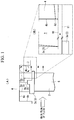
- FIG. 4 shows a schematic view of the configuration in the case where the blades are stationary blades and the structure body is a rotating shaft, which is an embodiment and a modification of the above-described first example.
- a rotating shaft (structure body) 20 has a rod-like shape that extends in the flow direction of the main flow of gas (main flow of fluid) passing through the above-described stationary blade rows (not shown) and moving blade rows 6 (see FIG. 1 ).
- the outer circumference of the rotating shaft 20 is formed in a recessed shape that is recessed toward the central axis of the rotating shaft 20.
- the recessed shape provided in the outer circumference of the rotating shaft 20 is defined by a wall surface (wall) 20a on the upstream side of the stationary blades (blades) 22, a wall surface 20b on the downstream side of the stationary blades 22, and a wall surface 20c connecting the wall surfaces 20a and 20b and located facing the radially inner side of stationary blade shrouds (shrouds) 23.
- the recessed shape provided in the outer circumference of the rotating shaft 20 is recessed toward the central axis of the rotating shaft 20.
- Seal fins 25 are connected, at base ends, to the wall surface 20c that is provided in the outer circumference of the rotating shaft 20 and forms the recessed shape.
- the seal fins 25 include at least one seal fin 25, for example, three seal fins.
- Each of the seal fins 25a, 25b, and 25c extend radially outward from the wall surface 20c of the rotating shaft 20 toward the stationary blade shrouds 23.
- the tips of the seal fins 25a, 25b, and 25c extending toward the stationary blade shrouds 23 are disposed a predetermined distance away from surfaces of the stationary blade shrouds 23 facing the rotating shaft 20 (hereinbelow, "inner circumferential surfaces").
- the number of seal fins 25 is not limited to three, but may be one, two, four or more.
- seal fins 25a, 25b, and 25c reduce the level of leakage of gas (leakage fluid) leaking out between the stationary blades 22 and the rotating shaft 20 and leaking out between the stationary blade shrouds 23 and the rotating shaft 20 toward the downstream side of the stationary blades 22.
- the predetermined distance between the inner circumferential surfaces of the stationary blade shrouds 23 and the tips of the seal fins 25a, 25b, and 25c in the radial direction is a radial distance that allows the level of leakage of gas leaking out between the stationary blades 22 and the rotating shaft 20 (hereinbelow, "leakage jet”) during operation to be reduced to a minimum.
- the stationary blades 22 have the stationary blade shrouds 23 at the tips thereof.
- the stationary blade shrouds 23 come into contact with adjacent shrouds and form a cylindrical shape.
- the inner circumferential surfaces of the stationary blade shrouds 23 are provided substantially parallel to the flow direction of the main flow of gas that has impinged on the stationary blades 22.
- a cavity (space) 27 is defined by downstream portions of the stationary blade shrouds 23, a downstream portion of the seal fin (sealing part) 25c located on the most downstream side among the seal fins 25, and the wall surfaces 20b and 20c located on the downstream side of the recessed shape in the rotating shaft 20, and communicates with the main flow of gas that has impinged on the stationary blades 22.
- a corner (end) 20d on the outer circumferential side of the wall surface 20b of the rotating shaft 20, which forms the cavity 27, is disposed away from a stationary-blade-shroud extension (shroud extension) 31 extending along the inner circumferential surfaces of the stationary blade shrouds 23 toward the downstream side of the stationary blade shrouds 23 and away from a seal-fin extension (sealing-part extension) 30 provided substantially parallel thereto at a predetermined distance and extending toward the downstream side of the seal fin 25c located on the most downstream side via the tip of the seal fin 25c located on the most downstream side, and is located on the opposite side of the stationary-blade-shroud extension 31 with respect to the seal-fin extension 30.
- the predetermined distance between the stationary-blade-shroud extension 31 and the seal-fin extension 30 is a radial distance that allows the level of leakage of the leakage jet leaking out between the stationary blade shrouds 31 and the seal fins 25 located on the most downstream side to be reduced to a minimum.
- the leakage jet led out from between the stationary blade shrouds 23 and the seal fin 25c located on the most downstream side is led out to an area between the seal-fin extension 30 and the stationary-blade-shroud extension 31.
- the corner 20d of the wall surface 20b on the downstream side of the rotating shaft 20 is disposed away from the stationary-blade-shroud extension 31 and from the seal-fin extension 30 and is located on the opposite side of the stationary-blade-shroud extension 31 with respect to the seal-fin extension 30, the leakage jet led out from between the seal-fin extension 30 and the stationary-blade-shroud extension 31 is led out toward the main flow of gas without colliding with the wall surface 20b or the corner 20d on the downstream side of the rotating shaft 20.
- the preferred inflow angle is 30° or less, but a smaller inflow angle is more preferable.
- an angle closer to parallel to the flow direction of the main flow of gas is more preferable, and an angle parallel to the flow direction of the main flow of gas is the most preferable.
- the leakage jet can be led out at a position away from the wall surface 20b and the corner (end) 20d on the downstream side of the rotating shaft 20, it is possible to prevent the leakage jet leaking out between the seal fin 25c located on the most downstream side and the stationary blade shrouds 23 from colliding with the wall surface 20b on the downstream side of the rotating shaft 20. Accordingly, it is possible to suppress a situation where the leakage jet collides with the wall surface 20b on the downstream side of the rotating shaft 20, the leakage jet, after collision, moves radially outward along the wall surface 20b on the downstream side of the rotating shaft 20, forming an eddy flowing counterclockwise, as indicated by dashed lines in FIG.
- the inner circumferential surfaces of the stationary blade shrouds 23 may have a shape other than the shape described in this modification, and they may be inclined like the outer circumferential surfaces on the downstream side of the moving blade shrouds 3b shown in FIG. 2 and moving blade shroud 3c shown in FIG. 3 .
- the inner circumferential surfaces on the downstream side of the stationary blade shrouds 23 disposed a predetermined distance away from the seal fin 25c located on the most downstream side may be inclined such that they gradually become farther away from the rotating shaft 20 along the flow direction of the main flow of gas that has impinged on the stationary blades 22 or may be inclined such that they gradually become closer to the rotating shaft 20 along the flow direction of the main flow of gas that has impinged on the stationary blades 22.
- the preferred inclination angle is 30° or less with respect to the flow direction of the main flow of gas that has impinged on the stationary blades 22, which is an inflow angle that does not greatly disturb the flow of the main flow of gas when the leakage jet joins the main flow of gas that has impinged on the stationary blades 22.
Landscapes
- Engineering & Computer Science (AREA)
- Mechanical Engineering (AREA)
- General Engineering & Computer Science (AREA)
- Physics & Mathematics (AREA)
- Fluid Mechanics (AREA)
- Chemical & Material Sciences (AREA)
- Combustion & Propulsion (AREA)
- Turbine Rotor Nozzle Sealing (AREA)
Description
- The present invention relates to a seal structure, a turbine machine having the same, and a power generating plant equipped with the same, and more specifically, it relates to fluid leaking out between a sealing part and shrouds at tips of stationary blades.
- In general, as shown in
FIG. 5 , a plurality ofmoving blades 51 of a turbine are provided with movingblade shrouds 53 at tips thereof so as to face aturbine casing 52. The movingblade shrouds 53 come into contact with adjacent shrouds and form an annular shape during rotation of the movingblades 51. Between the movingblade shrouds 53 and theturbine casing 52 is provided a seal portion in which seal fins 54 extending from theturbine casing 52 toward themoving blade shrouds 53 are connected to theturbine casing 52. Theseal fins 54 are provided to reduce the level of leakage of fluid, which is a main flow of fluid guided to the movingblades 51 and leaking out between the movingblade shrouds 53 and the turbine casing 52 (hereinbelow, "leakage jet") (for example,JP 2005-214051 A JP 2006-138259 A - However, in the inventions described in
JP 2005-214051 A JP 2006-291967 A FIG. 5 , the leakage jet (indicated by dashed lines inFIG. 5 ) guided to aspace 55 defined by a downstream-side wall 52a of theturbine casing 52, themoving blade shrouds 53, and the seal fins 54 collides with the downstream-side wall 52a of theturbine casing 52, moves radially inward along thewall 52a, and joins the main flow of fluid (indicated by solid lines inFIG. 5 ) after impinging on the movingblades 51 at a large angle (for example, 90°). There has been a problem in that, because the inflow angle of the leakage jet with respect to the main flow of fluid when the leakage jet joins the main flow of fluid is large, the leakage jet greatly disturbs the main flow of fluid, causing mixing loss (mixing loss) and decreased turbine efficiency. - Furthermore, when the leakage jet collides with the downstream-
side wall 52a of theturbine casing 52, the leakage jet, after collision, moves radially inward along the downstream-side wall 52a of theturbine casing 52. The leakage jet having moved radially inward along thewall 52a of theturbine casing 52 traps a portion of the main flow of fluid and generates an eddy in thespace 55, as indicated by dashed lines inFIG. 5 . Because a portion of the main flow of fluid is trapped in thespace 55, the flow of the main flow of fluid is greatly disturbed, resulting in a problem in that mixing loss (mixing loss) occurs. -
EP 2096262 A discloses a seal structure for shrouds of rotary blades of an axial flow turbine. The seal structure includes a turbine casing and a blade ring having shrouds formed at outer tip end portions of rotary blades and spaced apart from the casing to form a radial tip clearance through which a leakage flow is passing during operation of the turbine. The casing comprises plural sealing elements arranged in the radial gap facing the shrouds to reduce the shroud leakage flow. A deflector is provided at the casing downstream in the vicinity of the shroud step and extending in a radial direction towards the inward of the casing such that the deflector is still spaced in the radial direction from the outer radius level of the shroud step. -
JP 57-8302 A JP 2007-321721 A - The present invention has been made in view of these circumstances, and an object thereof is to provide a seal structure capable of suppressing disturbance of a flow of a main flow of fluid due to fluid leaking out of a seal portion of stationary blades, a turbine machine having the same, and a power generating plant equipped with the same.
- To overcome the above-described problems the present invention provides the seal structure with the features of
claim 1, the turbine machine having the same, and the power generating plant equipped with the same. - More specifically, the seal structure according to the present invention includes shrouds that are provided at tips of a plurality of stationary blades on which a main flow of fluid impinges in operation and that come into contact with adjacent shrouds to form a cylindrical shape; a sealing part connected to a rotating shaft (structure body) facing the shrouds; wherein the outer circumference of the rotating shaft is formed in a recessed shape that is recessed towards the central axis of the rotating shaft and a space that is defined by downstream sides of the shrouds, a downstream side of the sealing part, a wall surface of the recessed shape facing the radially inner side of the shrouds, and a wall of said recessed shape on a downstream side of the stationary blades on a downstream side of the rotating shaft and that communicates with the main flow of fluid that has impinged on the blades. A corner of the wall on the downstream side of the rotating shaft is formed so as to be disposed a predetermined distance away from a shroud extension extending toward the downstream side of the shrouds and away from a sealing-part extension provided substantially parallel to the shroud extension and extending toward the downstream side of the sealing part and so as to be located on an opposite side of the shroud extension with respect to the sealing-part extension.
- The fluid leaking out between the sealing part and the shrouds into the space is led out along the shroud extension extending toward the downstream side of the shroud and the sealing-part extension extending parallel thereto toward the downstream side of the sealing part. Thus, if there is a downstream-side wall of a structure body, such as a turbine casing or a rotating shaft, in an area between the sealing-part extension and the shroud extension, in other words, in the extending direction of the area through which the leakage fluid flows, the leakage fluid passing through the space collides with the downstream-side wall of the structure body. The leakage fluid that has collided with the wall of the structure body flows along the downstream-side wall of the structure body in the direction opposite to the structure body, i.e., toward the main flow of fluid. Because the space communicates with the main flow of fluid that has impinged on the blades, the fluid leaking out along the wall joins the main flow of fluid that has impinged on the blades at a large angle (for example, 90°). Thus, the flow of the main flow of fluid that has impinged on the blades is greatly disturbed.
- Furthermore, for example, in the case where the blades are the moving
blades 51 and the structure body is theturbine casing 52, as inFIG. 5 , the fluid leaking out into thespace 55 collides with the downstream-side wall 52a of theturbine casing 52, and the leakage fluid after collision moves radially inward along the downstream-side wall 52a of theturbine casing 52 and flows clockwise, as indicated by dashed lines inFIG. 5 . Thus, the leakage fluid flows in a direction opposite to the flow direction of the main flow of fluid that has impinged on the movingblades 51, trapping the main flow of fluid that has impinged on the movingblades 51 in thespace 55. Accordingly, the flow of the main flow of fluid that has impinged on the movingblades 51 is greatly disturbed. - In the case where the blades are
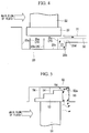
stationary blades 61 and the structure body is arotating shaft 62, as inFIG. 6 , the fluid leaking out into aspace 65 collides with a downstream-side wall 62a of therotating shaft 62, and a portion of the leakage fluid after collision moves radially outward along the downstream-side wall 62a of the rotatingshaft 62 and flows counterclockwise, as indicated by dashed lines inFIG. 6 . Thus, the leakage fluid flows in a direction opposite to the flow direction of the main flow of fluid that has impinged on thestationary blades 61, trapping the main flow of fluid that has impinged on thestationary blades 61 in thespace 65. Accordingly, the flow of the main flow of fluid that has impinged on thestationary blades 61 is greatly disturbed. - To counter such problems, in the present invention, an end of the downstream-side wall of the rotating shaft defining the space is disposed away from the shroud extension extending toward the downstream side of the shroud and away from the sealing-part extension extending parallel thereto toward the downstream side of the sealing part and is located on the opposite side of the shroud extension with respect to the sealing-part extension. With this configuration, it is possible to prevent the fluid leaking out between the sealing part and the shrouds from colliding with the downstream-side wall of the rotating shaft. Thus, the leakage fluid can be made to join the main flow of fluid that has impinged on the blades at a small inflow angle (for example, 30° or less). Accordingly, mixing loss caused by the leakage fluid joining the main flow of fluid can be reduced.
- Furthermore, because the leakage fluid can be led out at a position away from the end of the downstream-side wall (wall surface) of the rotating shaft, it is possible to prevent the fluid leaking out between the sealing part and the shrouds from colliding with the downstream-side wall of the rotating shaft.
- Thus, , in the case where the blades are the
stationary blades 61 and the structure body is therotating shaft 62, as inFIG. 6 , it is possible to prevent a situation where the leakage fluid collides with the downstream-side wall 62a of the rotatingshaft 62, and a portion of the leakage fluid after collision moves radially outward along the downstream-side wall 62a of the rotatingshaft 62 and flows counterclockwise, as indicated by dashed lines inFIG. 6 , trapping the main flow of fluid that has impinged on thestationary blades 61 in thespace 65. More specifically, the leakage fluid flows clockwise, which is a direction opposite to the direction shown by the dashed lines inFIG. 6 . Accordingly, it is possible to prevent the flow of the main flow of fluid that has impinged on thestationary blades 61 from being greatly disturbed, thereby reducing mixing loss caused by the leakage fluid joining the flow of the main flow of fluid. - The predetermined distance between the shroud extension and the sealing-part extension is a radial distance set such that the sealing part does not touch the shrouds during operation and such that the level of leakage of fluid leaking between the shrouds and the sealing part can be reduced to a minimum.
- Furthermore, in the seal structure according to the present invention, surfaces of the shrouds facing the structure body are preferably provided substantially parallel to a flow direction of the main flow of fluid that has impinged on the blades.
- The surfaces of the shrouds facing the structure body (i.e., the inner circumferential surfaces in the case of the stationary blades) are provided substantially parallel to the flow direction of the main flow of fluid that has impinged on the blades. Thus, the fluid leaking between the sealing part and the shrouds can be made to join the main flow of fluid that has impinged on the blades at a small angle. Accordingly, mixing loss caused by the leakage fluid joining the main flow of fluid can be reduced.
- Furthermore, in the seal structure according to the present invention, surfaces of the shrouds facing the structure body are preferably inclined such that they gradually become farther away from the structure body along a flow direction of the main flow of fluid that has impinged on the blades.
- The surfaces of the shrouds facing the structure body are provided in an inclined manner such that they gradually become farther away from the structure body along the flow direction of the main flow of fluid that has impinged on the blades. With this configuration, the leakage fluid can be led out at a position away from the downstream-side wall (wall surface) of the structure body, and thus, it is possible to prevent the fluid leaking out between the sealing part and the shrouds from colliding with the downstream-side wall of the structure body.
- Thus, , in the case where the blades are the
stationary blades 61 and the structure body is therotating shaft 62, as inFIG. 6 , it is possible to prevent a situation where the leakage fluid collides with the downstream-side wall 62a of the rotatingshaft 62, and a portion of the leakage fluid after collision moves radially outward along the downstream-side wall 62a of the rotatingshaft 62 and flows counterclockwise, as indicated by dashed lines inFIG. 6 , trapping the main flow of fluid that has impinged on thestationary blades 61 in thespace 65. More specifically, the leakage fluid flows clockwise, which is a direction opposite to the direction shown by the dashed lines inFIG. 6 . Accordingly, it is possible to prevent the flow of the main flow of fluid that has impinged on thestationary blades 61 from being greatly disturbed, thereby reducing mixing loss caused by the leakage fluid joining the flow of the main flow of fluid. - The angle at which the surfaces of the shrouds facing the structure body are inclined is set such that the leakage fluid does not greatly disturb the flow of the main flow of fluid that has impinged on the blades when it joins the main flow of fluid that has impinged on the blades.
- The preferred angle at which the leakage fluid is made to join the main flow of fluid that has impinged on the blades is 30° or less.
- Furthermore, in the seal structure according to the present invention, surfaces of the shrouds facing the structure body are preferably inclined such that they gradually become closer to the structure body along a flow direction of the main flow of fluid that has impinged on the blades.
- The surfaces of the shrouds facing the structure body are provided in an inclined manner such that they gradually become closer to the structure body along the flow direction of the main flow of fluid that has impinged on the blades. Thus, it is possible to prevent the fluid leaking out between the sealing part and the shrouds from directly joining the main flow of fluid that has impinged on the blades, and also it is possible to further prevent the main flow of fluid that has impinged on the blades from being trapped. Accordingly, mixing loss caused by the leakage fluid joining the main flow of fluid can be reduced.
- The angle at which the surfaces of the shrouds facing the structure body are inclined is set such that the leakage fluid does not greatly disturb the flow of the main flow of fluid that has impinged on the blades when it joins the main flow of fluid that has impinged on the blades.
- The preferred angle at which the leakage fluid is made to join the main flow of fluid that has impinged on the blades is 30° or less.
- Furthermore, a turbine machine according to the present invention includes any one of the above-described seal structures.
- A seal structure capable of reducing mixing loss caused when the leakage jet leaking out between the sealing part and the shrouds joins the main flow of fluid that has impinged on the blades is provided. This can prevent a drop in the turbine efficiency of the turbine machine.
- Furthermore, a power generating plant according to the present invention includes the above-described turbine machine.
- The turbine machine capable of preventing a drop in the turbine efficiency is provided. This can prevent a drop in the power generating efficiency of the power generating plant.
- An end of the downstream-side wall of the structure body defining the space is disposed away from the shroud extension extending toward the downstream side of the shroud and away from the sealing-part extension extending parallel thereto toward the downstream side of the sealing part and is located on the opposite side of the shroud extension with respect to the sealing-part extension. With this configuration, it is possible to prevent the fluid leaking out between the sealing part and the shrouds from colliding with the downstream-side wall of the structure body. Thus, the leakage fluid can be made to join the main flow of fluid that has impinged on the blades at a small inflow angle (for example, 30° or less). Accordingly, mixing loss caused by the leakage fluid joining the main flow of fluid can be reduced.
- Furthermore, because the leakage fluid can be led out at a position away from the end of the downstream-side wall (wall surface) of the structure body, it is possible to prevent the fluid leaking out between the sealing part and the shrouds from colliding with the downstream-side wall of the structure body.
-
- {
FIG. 1} FIG. 1 shows a seal structure of a gas turbine in a power generating plant according to a first example serving to explain features of the present invention, in which (A) is a schematic view of the configuration thereof and (B) is a partial enlarged view thereof. - {
FIG. 2} FIG. 2 shows a seal structure of a gas turbine in a power generating plant according to a second example serving to explain features of the present invention, in which (A) is a schematic view of the configuration thereof and (B) is a partial enlarged view thereof. - {
FIG. 3} FIG. 3 shows a seal structure of a gas turbine in a power generating plant according to a third example serving to explain features of the present invention, in which (A) is a schematic view of the configuration thereof and (B) is a partial enlarged view thereof. - {
FIG. 4} FIG. 4 is a schematic view of the configuration of a seal structure of a gas turbine in a power generating plant according to an embodiment of the present invention which is a modification of the first example. - {
FIG. 5} FIG. 5 is a schematic view of the configuration of a seal structure between moving blades and a turbine casing of a turbine machine in a conventional power generating plant. - {
FIG. 6} FIG. 6 is a schematic view of the configuration of a seal structure between stationary blades and a rotating shaft of a turbine machine in a conventional power generating plant. -
FIG. 1 shows a seal structure of a gas turbine (a turbine machine) of a power generating plant according to a first example serving to explain features of the invention, in which (A) is a schematic view of the configuration thereof and (B) is a partial enlarged view thereof. - A gas turbine installed in a power generating plant includes stationary blades (not shown) that direct a flow of a main flow of gas (main flow of fluid), which is combustion gas that has been guided into the gas turbine, to a plurality of moving blades (blades) 2, the moving
blades 2 on which the main flow of gas that has passed through the stationary blades impinges, moving blade shrouds 3 (3a) that are provided at tips of the movingblades 2 and come into contact with adjacent shrouds to form a cylindrical shape, and a turbine casing (structure body) 4 enclosing the movingblades 2 and the moving blade shrouds (shrouds) 3a therein. - The
turbine casing 4 has a cylindrical shape surrounding the outer circumferences of the movingblade shrouds 3a provided at the tips of the movingblades 2. As shown inFIG. 1(A) , the inner circumference of theturbine casing 4 is formed in a recessed shape that is recessed toward the outer circumference of theturbine casing 4. The recessed shape provided in the inner circumference of theturbine casing 4 is defined by a wall surface (wall) 4a on the upstream side of the movingblades 2, awall surface 4b on the downstream side of the movingblades 2, and awall surface 4c connecting thewall surface 4a and thewall surface 4b and located facing the radially outer side of the movingblade shrouds 3a. Thus, the recessed shape provided in the inner circumference of theturbine casing 4 is recessed toward the outer circumference of theturbine casing 4. - The
seal fins 5 are connected, at base ends, to thewall surface 4c forming the recessed shape provided in the inner circumference of theturbine casing 4. Theseal fins 5 include at least one seal fin, for example, three seal fins. Theseal fins wall surface 4c of theturbine casing 4 radially inward toward the movingblade shrouds 3a. The tips of theseal fins blade shrouds 3a are disposed a predetermined distance away from surfaces of the movingblade shrouds 3a facing the turbine casing 4 (hereinbelow, "outer circumferential surfaces"). The number ofseal fins 5 is not limited to three, but may be one, two, four or more. - These
seal fins blades 2 and theturbine casing 4 and leaking out between the movingblade shrouds 3a and theturbine casing 4 toward the downstream side of the movingblades 2. The predetermined distance between the outer circumferential surfaces of the movingblade shrouds 3a and the tips of theseal fins blade shrouds 3a mechanically touch theseal fins blades 2 and the turbine casing 4 (hereinbelow, "leakage jet") can be reduced to a minimum. - The plurality of moving
blades 2 are provided in the circumferential direction of a rotating shaft (not shown). The plurality of movingblades 2 constitute movingblade rows 6. The movingblade rows 6 and stationary blade rows (not shown), in which stationary blades are provided in the circumferential direction of the rotating shaft, are provided alternately in multiple stages in the axial direction. The main flow of gas impinges on the movingblades 2. Thus, the gas turbine is rotationally driven. The main flow of gas that has impinged on the movingblades 2 is guided to the stationary blade rows provided on the downstream side. - A cavity (space) 7 is defined by downstream portions of the moving
blade shrouds 3a, a downstream portion of theseal fin 5c (sealing part in the present invention) located on the most downstream side among theseal fins 5, and the wall surfaces 4b and 4c of theturbine casing 4 on the downstream side of the recessed shape, and communicates with the main flow of gas that has impinged on the movingblades 2. As shown inFIG. 1(B) , a corner (end) 4d, on the inner circumference side, of thewall surface 4b of theturbine casing 4 forming thecavity 7 is disposed away from a moving-blade-shroud extension (shroud extension) 11 extending along the outer circumferential surfaces of the movingblade shrouds 3a toward the downstream side of the movingblade shrouds 3a and away from a seal-fin extension (sealing-part extension) 10 provided substantially parallel thereto at a predetermined distance and extending toward the downstream side of theseal fin 5c located on the most downstream side via the tip of theseal fin 5c located on the most downstream side, and is located on the opposite side of the moving-blade-shroud extension 11 with respect to the seal-fin extension 10. - The predetermined distance between the moving-blade-
shroud extension 11 and the seal-fin extension 10 is a radial distance set such that theseal fins blade shrouds 3a during operation and such that the level of leakage of the leakage jet leaking out between the movingblade shrouds 3a and theseal fins - The moving
blade shrouds 3a are provided at the tips of the movingblades 2. The movingblade shrouds 3a come into contact with adjacent shrouds and form a cylindrical shape. As shown inFIG. 1(A) , the outer circumferential surfaces of the movingblade shrouds 3a have a stepped shape having steps arranged in the flow direction of the main flow of gas impinging on the movingblades 2. The movingblade shrouds 3a have, at the middle parts thereof in the flow direction of the main flow of gas, projections protruding toward the turbine casing 4 (outer circumferential side). The outer circumferential surfaces of the movingblade shrouds 3a on the upstream side, at the middle part, and on the downstream side are formed substantially parallel to the flow direction of the main flow of gas after impinging on the movingblades 2. By making the movingblade shrouds 3a have a stepped shape, the sealing effect between the movingblade shrouds 3a and theturbine casing 4 is increased. - The shape of the moving
blade shrouds 3a is not limited to a stepped shape, but may be another shape. - Next, the flows of the main flow of gas and the leakage jet will be described.
- The main flow of gas that has been guided to the gas turbine is guided from the stationary blade rows to the moving
blade rows 6. The main flow of gas that has been guided to the movingblade rows 6 impinges on the movingblades 2 and drives the gas turbine. The main flow of gas after impinging on the movingblades 2 is guided to the stationary blade rows provided on the downstream side. - Furthermore, a portion of the main flow of gas impinging on the moving
blades 2 leaks out from the upstream side of the movingblades 2 to a space between the movingblade shrouds 3a and theturbine casing 4. The main flow of gas leaking out to the space between the movingblade shrouds 3a and theturbine casing 4 is led out from between the movingblade shrouds 3a and theseal fin 5c on the most downstream side, becoming a leakage jet. - The leakage jet led out from between the moving
blade shrouds 3a and theseal fin 5c on the most downstream side is led out to an area between the seal-fin extension 10 and the moving-blade-shroud extension 11 (hereinbelow, a "leakage-jet flowing area"). Herein, because thecorner 4d of thewall surface 4b on the downstream side of theturbine casing 4 is disposed away from the moving-blade-shroud extension 11 and from the seal-fin extension 10 and is located on the opposite side of the moving-blade-shroud extension 11 with respect to the seal-fin extension 10, the leakage jet led out of the leakage-jet flowing area is led out toward the main flow of gas without colliding with thewall surface 4b or thecorner 4d on the downstream side of theturbine casing 4. - The leakage jet led out of the leakage-jet flowing area joins the main flow of gas that has impinged on the moving
blades 2 at a small inflow angle with respect to the flow direction thereof. The preferred inflow angle is 30° or less, but a smaller inflow angle is more preferable. Thus, an angle closer to parallel to the flow direction of the main flow of gas is more preferable, and an angle parallel to the flow direction of the main flow of gas is the most preferable. - Furthermore, because the leakage jet can be led out at a position away from the
wall surface 4b and thecorner 4d on the downstream side of theturbine casing 4, it is possible to prevent the leakage jet leaking out between theseal fin 5c located on the most downstream side and the movingblade shrouds 3a from colliding with thewall surface 4b on the downstream side of theturbine casing 4. Accordingly, it is possible to suppress a situation where the leakage jet collides with thewall surface 4b on the downstream side of theturbine casing 4, the leakage jet, after collision, moves radially inward along thewall surface 4b on the downstream side of theturbine casing 4, forming an eddy flowing clockwise, as indicated by dashed lines inFIG. 5 , and the eddy and the main flow of gas flow in opposite directions when the eddy joins the main flow of gas, trapping the main flow of gas that has impinged on the movingblades 2 in thecavity 7. That is, the leakage jet flows counterclockwise in thecavity 7, as indicated by dashed lines inFIG. 1(A) . - The seal structure, the turbine machine having the same, and the power generating plant equipped with the same described above provide the following advantages.
- The corner (end) 4d of the wall surface (wall) 4b on the downstream side of the turbine casing (structure body) 4 forming the cavity (space) 7 is disposed away from the moving-blade-shroud extension (shroud extension) 11 extending toward the downstream side of the moving blade shrouds (shrouds) 3a and away from the seal-fin extension (sealing-part extension) 10 extending parallel thereto toward the downstream side of the seal fin (sealing part) 5c located on the most downstream side, and is located on the opposite side of the moving-blade-
shroud extension 11 with respect to the seal-fin extension 10. With this configuration, it is possible to prevent the leakage jet (leakage fluid) leaking out between theseal fin 5c located on the most downstream side and the movingblade shrouds 3a from colliding with thewall surface 4b on the downstream side of theturbine casing 4. Thus, the leakage jet can join the main flow of gas (main flow of fluid) that has impinged on the moving blades (blades) 2 at a small inflow angle. Accordingly, mixing loss caused by the leakage jet joining the main flow of gas can be reduced. - Furthermore, because the leakage jet can be led out at a position away from the
wall surface 4b on the downstream side of theturbine casing 4, it is possible to prevent the leakage jet leaking out between theseal fin 5c located on the most downstream side and the movingblade shrouds 3a from colliding with thewall surface 4b on the downstream side of theturbine casing 4. Accordingly, it is possible to suppress a situation where the leakage jet collides with thewall surface 4b on the downstream side of theturbine casing 4, the leakage jet, after collision, moves radially inward along thewall surface 4b on the downstream side of theturbine casing 4, forming an eddy flowing clockwise, as indicated by dashed lines inFIG. 5 , and the eddy and the main flow of gas flow in opposite directions when the eddy joins the main flow of gas, trapping the main flow of gas that has impinged on the movingblades 2 in thecavity 7. That is, the leakage jet flows counterclockwise, as indicated by dashed lines inFIG. 1(A) , in thecavity 7. Accordingly, because the flow direction of the leakage jet when joining the main flow of gas that has impinged on the movingblades 2 is substantially the same as that of the main flow of gas, the flow of the main flow of gas that has impinged on the movingblades 2 is prevented from being greatly disturbed. Thus, mixing loss caused by the leakage jet joining the flow of the main flow of gas can be reduced. - The surfaces (outer circumferential surfaces) of the moving
blade shrouds 3a facing theturbine casing 4 are provided substantially parallel to the flow direction of the main flow of gas that has impinged on the movingblades 2. Thus, the leakage jet leaking out between theseal fin 5c located on the most downstream side and the movingblade shrouds 3a can be made to join the main flow of gas that has impinged on the movingblades 2 at a small inflow angle. Accordingly, mixing loss caused by the leakage jet joining the main flow of gas can be reduced. - A seal structure capable of reducing mixing loss caused when the leakage jet leaking out between the
seal fin 5c located on the most downstream side and the movingblade shrouds 3a joins the main flow of gas that has impinged on the movingblades 2 is provided. This can prevent a drop in the turbine efficiency of the gas turbine (turbine machine). - A gas turbine (turbine machine) capable of preventing a drop in the turbine efficiency is provided. This can prevent a drop in the power generating efficiency of the power generating plant.
- A second example serving to explain features of the inventionof the present invention will be described below. Although a seal structure, a turbine machine having the same, and a power generating plant equipped with the same according to this example differ from those according to the first example in that the outer circumferential surfaces on the downstream side of the moving blade shrouds disposed a predetermined distance away from the seal fin (sealing part) 5c located on the most downstream side gradually become farther away from the inside of the turbine casing in the flow direction of the main flow of gas that has impinged on the moving blades, the other configurations are the same. Accordingly, the same configurations and the same flow will be denoted by the same reference numerals, and descriptions thereof will be omitted.
-
FIG. 2 shows a seal structure of a gas turbine in a power generating plant according to a second example serving to explain features of the present invention, in which (A) is a schematic view of the configuration thereof and (B) is a partial enlarged view thereof. - The outer circumferential surfaces on the downstream side of moving blade shrouds (shrouds) 3b (the surfaces facing the turbine casing 4) are inclined from projections provided at the middle parts of the moving
blade shrouds 3b such that they gradually become farther away from the inside of the turbine casing (structure body) 4 along the flow direction of the main flow of gas (main flow) that has impinged on the moving blades (blades) 2. The rate at which the outer circumferential surfaces on the downstream side of the movingblade shrouds 3b gradually become farther away from the inside of theturbine casing 4, i.e., the inclination angle, is desirably 30° or less with respect to the flow direction of the main flow of gas that has impinged on the movingblades 2, which is an inflow angle that does not greatly disturb the flow of the main flow of gas when the leakage jet (leakage fluid) joins the main flow of gas that has impinged on the movingblades 2. - The leakage jet led out from between the
seal fin 5c located on the most downstream side and the movingblade shrouds 3b is led out toward the main flow of gas without colliding with the wall surface (wall) 4b or the corner (end) 4d of theturbine casing 4. - Furthermore, the leakage jet led out from between the
seal fin 5c located on the most downstream side and the movingblade shrouds 3b joins the main flow of gas that has impinged on the movingblades 2 at a small inflow angle with respect to the flow direction thereof. - As has been described, the seal structure, the turbine machine having the same, and the power generating plant equipped with the same according to this example provide the following advantages.
- The outer circumferential surfaces on the downstream side of the moving blade shrouds (shrouds) 3b (the surfaces facing the turbine casing 4) are inclined such that they gradually become farther away from the turbine casing (structure body) 4 along the flow direction of the main flow of gas (main flow of fluid) that has impinged on the moving blades (blades) 2. With this configuration, the leakage jet (leakage fluid) can be led out at a position away from the wall surface (wall) 4b on the downstream side of the
turbine casing 4, and thus, it is possible to prevent the leakage jet leaking out between the seal fin (sealing part) 5c located on the most downstream side and the movingblade shrouds 3b from colliding with thewall surface 4b on the downstream side of theturbine casing 4. Accordingly, it is possible to suppress a situation where the leakage jet collides with thewall surface 4b on the downstream side of theturbine casing 4, and the leakage jet, after collision, moves radially inward along thewall surface 4b on the downstream side of theturbine casing 4, forming a clockwise eddy in the cavity 7(space), as indicated by dashed lines inFIG. 5 , and trapping the main flow of gas that has impinged on the movingblades 2 in thecavity 7. That is, the leakage jet flows counterclockwise in thecavity 7, as indicated by dashed lines inFIG. 2(A) . Accordingly, it is possible to prevent the flow of the main flow of gas that has impinged on the movingblades 2 from being greatly disturbed and to reduce mixing loss caused by the leakage jet joining the main flow of gas. - Third Example
- A third example serving to explain features of the inventionof the present invention will be described below. Although a seal structure, a turbine machine having the same, and a power generating plant equipped with the same according to this example differ from those according to the first example in that the outer circumferential surfaces on the downstream side of the moving blade shrouds disposed a predetermined distance away from the seal fin (sealing part) 5c located on the most downstream side gradually become closer to the inside of the turbine casing in the flow direction of the main flow of gas that has impinged on the moving blades, the other configurations are the same. Accordingly, the same configurations and the same flow will be denoted by the same reference numerals, and descriptions thereof will be omitted.
-
FIG. 3 shows a seal structure of a gas turbine in a power generating plant according to a third example serving to explain features of the present invention, in which (A) is a schematic view of the configuration thereof and (B) is a partial enlarged view thereof. - The outer circumferential surfaces on the downstream side of moving blade shrouds (shrouds) 3c (the surfaces facing the turbine casing 4) are inclined from the projections provided at the middle parts of the moving
blade shrouds 3c such that they gradually become closer to the inside of the turbine casing (structure body) 4 along the flow direction of the main flow of gas (main flow) that has impinged on the moving blades (blades) 2. The rate at which the outer circumferential surfaces of the moving blade shrouds 3c on the downstream side gradually become closer to the inside of theturbine casing 4, i.e., the inclination angle, is desirably 30° or less with respect to the flow direction of the main flow of gas that has impinged on the movingblades 2, which is an inflow angle that does not greatly disturb the flow of the main flow of gas when the leakage jet (leakage fluid) joins the main flow of gas that has impinged on the movingblades 2. - The leakage jet led out from between the seal fin (sealing part) 5c located on the most downstream side and the moving
blade shrouds 3c is led out toward the main flow of gas without colliding with the wall surface (wall) 4b or corner (end) 4d of theturbine casing 4. - Furthermore, the leakage jet led out from between the
seal fin 5c located on the most downstream side and the movingblade shrouds 3c joins the main flow of gas that has impinged on the movingblades 2 at a small inflow angle with respect to the flow direction thereof. - As has been described, the seal structure, the turbine machine having the same, and the power generating plant equipped with the same according to this example provide the following advantages.
- The outer circumferential surfaces of the moving blade shrouds (shrouds) 3c on the downstream side (the surfaces facing the turbine casing 4) are inclined such that they gradually become closer to the turbine casing (structure body) 4 along the flow direction of the main flow of gas (main flow of fluid) that has impinged on the moving blades (blades) 2. Thus, the leakage jet (leakage fluid) leaking out between the seal fin (sealing part) 5c located on the most downstream side and the moving
blade shrouds 3c does not directly join the main flow of gas that has impinged on the movingblades 2, and it is possible to further prevent the main flow of gas that has impinged on the movingblades 2 from being trapped in the cavity (space). Accordingly, mixing loss caused by the leakage jet joining the main flow of gas can be reduced. - Although a description has been given by using a gas turbine as the turbine machine in the above first to third examples, the turbine machine may be another turbine machine, such as a steam turbine.
- Furthermore, although the above first to third examples have been described assuming that the blades are the moving
blades 2 and the structure body is theturbine casing 4, the present invention is directed to a case where the blades are stationary blades, and the structure body is a rotating shaft. -
FIG. 4 shows a schematic view of the configuration in the case where the blades are stationary blades and the structure body is a rotating shaft, which is an embodiment and a modification of the above-described first example. - A rotating shaft (structure body) 20 has a rod-like shape that extends in the flow direction of the main flow of gas (main flow of fluid) passing through the above-described stationary blade rows (not shown) and moving blade rows 6 (see
FIG. 1 ). The outer circumference of therotating shaft 20 is formed in a recessed shape that is recessed toward the central axis of therotating shaft 20. The recessed shape provided in the outer circumference of therotating shaft 20 is defined by a wall surface (wall) 20a on the upstream side of the stationary blades (blades) 22, awall surface 20b on the downstream side of thestationary blades 22, and awall surface 20c connecting the wall surfaces 20a and 20b and located facing the radially inner side of stationary blade shrouds (shrouds) 23. Thus, the recessed shape provided in the outer circumference of therotating shaft 20 is recessed toward the central axis of therotating shaft 20. -
Seal fins 25 are connected, at base ends, to thewall surface 20c that is provided in the outer circumference of therotating shaft 20 and forms the recessed shape. Theseal fins 25 include at least oneseal fin 25, for example, three seal fins. Each of theseal fins wall surface 20c of therotating shaft 20 toward the stationary blade shrouds 23. The tips of theseal fins seal fins 25 is not limited to three, but may be one, two, four or more. - These
seal fins stationary blades 22 and therotating shaft 20 and leaking out between the stationary blade shrouds 23 and therotating shaft 20 toward the downstream side of thestationary blades 22. The predetermined distance between the inner circumferential surfaces of the stationary blade shrouds 23 and the tips of theseal fins stationary blades 22 and the rotating shaft 20 (hereinbelow, "leakage jet") during operation to be reduced to a minimum. - The
stationary blades 22 have the stationary blade shrouds 23 at the tips thereof. The stationary blade shrouds 23 come into contact with adjacent shrouds and form a cylindrical shape. The inner circumferential surfaces of the stationary blade shrouds 23 are provided substantially parallel to the flow direction of the main flow of gas that has impinged on thestationary blades 22. - A cavity (space) 27 is defined by downstream portions of the stationary blade shrouds 23, a downstream portion of the seal fin (sealing part) 25c located on the most downstream side among the
seal fins 25, and the wall surfaces 20b and 20c located on the downstream side of the recessed shape in therotating shaft 20, and communicates with the main flow of gas that has impinged on thestationary blades 22. A corner (end) 20d on the outer circumferential side of thewall surface 20b of therotating shaft 20, which forms thecavity 27, is disposed away from a stationary-blade-shroud extension (shroud extension) 31 extending along the inner circumferential surfaces of the stationary blade shrouds 23 toward the downstream side of the stationary blade shrouds 23 and away from a seal-fin extension (sealing-part extension) 30 provided substantially parallel thereto at a predetermined distance and extending toward the downstream side of theseal fin 25c located on the most downstream side via the tip of theseal fin 25c located on the most downstream side, and is located on the opposite side of the stationary-blade-shroud extension 31 with respect to the seal-fin extension 30. - The predetermined distance between the stationary-blade-
shroud extension 31 and the seal-fin extension 30 is a radial distance that allows the level of leakage of the leakage jet leaking out between the stationary blade shrouds 31 and theseal fins 25 located on the most downstream side to be reduced to a minimum. - Next, the flows of the main flow of gas and the leakage jet will be described.
- A portion of the main flow of gas that has been guided to the
stationary blades 22 leaks out from the upstream side of thestationary blades 22 to a space between the stationary blade shrouds 23 and therotating shaft 20. The main flow of gas leaking out to the space between the stationary blade shrouds 23 and therotating shaft 20 is led out from between the stationary blade shrouds 23 and theseal fin 25c located on the most downstream side, becoming a leakage jet. - The leakage jet led out from between the stationary blade shrouds 23 and the
seal fin 25c located on the most downstream side is led out to an area between the seal-fin extension 30 and the stationary-blade-shroud extension 31. Herein, because thecorner 20d of thewall surface 20b on the downstream side of therotating shaft 20 is disposed away from the stationary-blade-shroud extension 31 and from the seal-fin extension 30 and is located on the opposite side of the stationary-blade-shroud extension 31 with respect to the seal-fin extension 30, the leakage jet led out from between the seal-fin extension 30 and the stationary-blade-shroud extension 31 is led out toward the main flow of gas without colliding with thewall surface 20b or thecorner 20d on the downstream side of therotating shaft 20. - The leakage jet led out from between the seal-
fin extension 30 and the stationary-blade-shroud extension 31 joins the main flow of gas that has impinged on thestationary blades 22 at a small inflow angle with respect to the flow direction thereof. The preferred inflow angle is 30° or less, but a smaller inflow angle is more preferable. Thus, an angle closer to parallel to the flow direction of the main flow of gas is more preferable, and an angle parallel to the flow direction of the main flow of gas is the most preferable. - Furthermore, because the leakage jet can be led out at a position away from the
wall surface 20b and the corner (end) 20d on the downstream side of therotating shaft 20, it is possible to prevent the leakage jet leaking out between theseal fin 25c located on the most downstream side and the stationary blade shrouds 23 from colliding with thewall surface 20b on the downstream side of therotating shaft 20. Accordingly, it is possible to suppress a situation where the leakage jet collides with thewall surface 20b on the downstream side of therotating shaft 20, the leakage jet, after collision, moves radially outward along thewall surface 20b on the downstream side of therotating shaft 20, forming an eddy flowing counterclockwise, as indicated by dashed lines inFIG. 6 , and the eddy and the main flow of gas flow in opposite directions when the eddy joins the main flow of gas, trapping the main flow of gas that has impinged on thestationary blades 22 in thecavity 27. That is, the leakage jet flows clockwise in thecavity 27, as indicated by dashed lines inFIG. 4 . - Thus, it is possible to make the leakage jet join the flow of the main flow of gas that has impinged on the
stationary blades 22 without greatly disturbing it and to reduce mixing loss caused by the leakage jet joining the flow of the main flow of gas. - The inner circumferential surfaces of the stationary blade shrouds 23 may have a shape other than the shape described in this modification, and they may be inclined like the outer circumferential surfaces on the downstream side of the moving
blade shrouds 3b shown inFIG. 2 and movingblade shroud 3c shown inFIG. 3 . - That is, the inner circumferential surfaces on the downstream side of the stationary blade shrouds 23 disposed a predetermined distance away from the
seal fin 25c located on the most downstream side may be inclined such that they gradually become farther away from the rotatingshaft 20 along the flow direction of the main flow of gas that has impinged on thestationary blades 22 or may be inclined such that they gradually become closer to therotating shaft 20 along the flow direction of the main flow of gas that has impinged on thestationary blades 22. - If the inner circumferential surfaces on the downstream side of the stationary blade shrouds 23 are inclined as above, the preferred inclination angle is 30° or less with respect to the flow direction of the main flow of gas that has impinged on the
stationary blades 22, which is an inflow angle that does not greatly disturb the flow of the main flow of gas when the leakage jet joins the main flow of gas that has impinged on thestationary blades 22. -
- 2 moving blade (blade)
- 3 (3a, 3b, 3c) moving blade shroud (shroud)
- 4 turbine casing (structure body)
- 4b wall surface (wall)
- 4d corner (end)
- 5c seal fin (sealing part) located on the most downstream side
- 7 cavity (space)
- 10 seal-fin extension (sealing-part extension)
- 11 moving-blade-shroud extension (shroud extension)
Claims (6)
- A seal structure comprising:shrouds (23) that are provided at tips of a plurality of stationary blades (22) on which a main flow of fluid impinges in operation and that come into contact with adjacent shrouds (23) to form a cylindrical shape;a sealing part (25c) connected to a rotating shaft (20) facing the shrouds (23);wherein the outer circumference of the rotating shaft (20) is formed in a recessed shape that is recessed towards the central axis of the rotating shaft (20) and that partially encloses the shrouds (23); anda space (27) that is defined by downstream sides of the shrouds (23), a downstream side of the sealing part (25c), a wall surface (20c) of the recessed shape facing the radially inner side of the shrouds (23), and a wall (20b) of said recessed shape on a downstream side of the stationary blades (22), on a downstream side of the rotating shaft (20) and that communicates with the main flow of fluid that has impinged on the stationary blades (22),wherein a corner (20d) of the wall (20b) on the downstream side of the rotating shaft (20) is formed so as to be disposed at a predetermined distance away from a shroud extension (31) extending toward the downstream side of the shrouds (23) and away from a sealing-part extension (30) provided substantially parallel to the shroud extension (31) and extending toward the downstream side of the sealing part (25c) and so as to be located radially on an opposite side of the shroud extension (31) with respect to the sealing part extension (30).
- The seal structure according to claim 1, wherein surfaces of the shrouds (23) facing the rotating shaft (20) are provided substantially parallel to a flow direction of the main flow of fluid that has impinged on the stationary blades (22).
- The seal structure according to claim 1, wherein surfaces of the shrouds (23) facing the rotating shaft (20) are inclined such that they gradually become farther away from the rotating shaft (20) along a flow direction of the main flow of fluid impinging on the stationary blades (22).
- The seal structure according to claim 1, wherein surfaces of the shrouds (23) facing the rotating shaft (20) are inclined such that they gradually become closer to the rotating shaft (20) along a flow direction of the main flow of fluid impinging on the stationary blades (22).
- A turbine machine comprising the seal structure according to any one of claims 1 to 4.
- A power generating plant comprising the turbine machine according to claim 5.
Applications Claiming Priority (2)
| Application Number | Priority Date | Filing Date | Title |
|---|---|---|---|
| JP2010120631A JP5574825B2 (en) | 2010-05-26 | 2010-05-26 | Seal structure, turbine machine including the same, and power plant including the same |
| PCT/JP2011/061770 WO2011148899A1 (en) | 2010-05-26 | 2011-05-23 | Seal structure, turbine machine equipped with same, and power plant equipped with said turbine machine |
Publications (3)
| Publication Number | Publication Date |
|---|---|
| EP2578810A1 EP2578810A1 (en) | 2013-04-10 |
| EP2578810A4 EP2578810A4 (en) | 2013-10-16 |
| EP2578810B1 true EP2578810B1 (en) | 2016-05-04 |
Family
ID=45003889
Family Applications (1)
| Application Number | Title | Priority Date | Filing Date |
|---|---|---|---|
| EP11786598.0A Active EP2578810B1 (en) | 2010-05-26 | 2011-05-23 | Seal structure, turbine machine equipped with same, and power plant equipped with said turbine machine |
Country Status (6)
| Country | Link |
|---|---|
| US (1) | US20130094945A1 (en) |
| EP (1) | EP2578810B1 (en) |
| JP (1) | JP5574825B2 (en) |
| KR (1) | KR101506379B1 (en) |
| CN (1) | CN102822450B (en) |
| WO (1) | WO2011148899A1 (en) |
Families Citing this family (13)
| Publication number | Priority date | Publication date | Assignee | Title |
|---|---|---|---|---|
| JP5591042B2 (en) | 2010-09-17 | 2014-09-17 | 三菱重工業株式会社 | Turbine |
| JP5518032B2 (en) * | 2011-12-13 | 2014-06-11 | 三菱重工業株式会社 | Turbine and seal structure |
| JP5916458B2 (en) | 2012-03-23 | 2016-05-11 | 三菱日立パワーシステムズ株式会社 | Turbine |
| JP5567077B2 (en) * | 2012-08-23 | 2014-08-06 | 三菱重工業株式会社 | Rotating machine |
| JP5985351B2 (en) | 2012-10-25 | 2016-09-06 | 三菱日立パワーシステムズ株式会社 | Axial flow turbine |
| JP6131177B2 (en) * | 2013-12-03 | 2017-05-17 | 三菱重工業株式会社 | Seal structure and rotating machine |
| JP2016109087A (en) * | 2014-12-09 | 2016-06-20 | 株式会社東芝 | Water power machine |
| JP6638938B2 (en) * | 2016-03-25 | 2020-02-05 | 三菱日立パワーシステムズ株式会社 | Rotating machinery |
| JP2018003812A (en) * | 2016-07-08 | 2018-01-11 | 三菱日立パワーシステムズ株式会社 | Bucket and turbine using the same |
| JP6153650B2 (en) * | 2016-08-03 | 2017-06-28 | 三菱日立パワーシステムズ株式会社 | Steam turbine stationary body and steam turbine provided with the same |
| CN108918046B (en) * | 2018-06-06 | 2019-10-11 | 南京航空航天大学 | Hot disk edge obturages leakage characteristics experimental rig and method |
| JP7223570B2 (en) | 2018-12-06 | 2023-02-16 | 三菱重工業株式会社 | Turbine rotor blade, turbine and tip clearance measurement method |
| JP7356285B2 (en) | 2019-07-31 | 2023-10-04 | 三菱重工業株式会社 | axial flow turbine |
Family Cites Families (16)
| Publication number | Priority date | Publication date | Assignee | Title |
|---|---|---|---|---|
| US4370094A (en) * | 1974-03-21 | 1983-01-25 | Maschinenfabrik Augsburg-Nurnberg Aktiengesellschaft | Method of and device for avoiding rotor instability to enhance dynamic power limit of turbines and compressors |
| JPS578302A (en) * | 1980-06-19 | 1982-01-16 | Hitachi Ltd | Internal stage structure of multistage axial-flow machine |
| DE3523469A1 (en) * | 1985-07-01 | 1987-01-08 | Bbc Brown Boveri & Cie | Contact-free controlled-gap seal for turbo-machines |
| JPH0693803A (en) * | 1992-09-10 | 1994-04-05 | Hitachi Ltd | Labyrinth packing |
| EP0799973B1 (en) * | 1996-04-01 | 2002-07-03 | Alstom | Wall contour for an axial turbomachine |
| EP0894944A1 (en) * | 1997-07-29 | 1999-02-03 | Siemens Aktiengesellschaft | Turbine blading |
| DE59808709D1 (en) * | 1998-11-10 | 2003-07-17 | Alstom Switzerland Ltd | Tip seal for turbine blades |
| JP2002371802A (en) * | 2001-06-14 | 2002-12-26 | Mitsubishi Heavy Ind Ltd | Shroud integrated type moving blade in gas turbine and split ring |
| US7059821B2 (en) * | 2003-05-07 | 2006-06-13 | General Electric Company | Method and apparatus to facilitate sealing within turbines |
| JP2005214051A (en) * | 2004-01-28 | 2005-08-11 | Toshiba Corp | Axial-flow turbine stage and axial-flow turbine |
| JP2006138259A (en) * | 2004-11-12 | 2006-06-01 | Mitsubishi Heavy Ind Ltd | Axial flow turbine |
| JP2006291967A (en) | 2006-05-29 | 2006-10-26 | Toshiba Corp | Axial flow turbine |
| JP2007321721A (en) * | 2006-06-05 | 2007-12-13 | Toshiba Corp | Axial flow turbine stage and axial flow turbine |
| JP2009085185A (en) * | 2007-10-03 | 2009-04-23 | Toshiba Corp | Axial flow turbine and axial flow turbine stage structure |
| EP2096262A1 (en) * | 2008-02-26 | 2009-09-02 | Siemens Aktiengesellschaft | Axial flow turbine with low shroud leakage losses |
| GB0822416D0 (en) * | 2008-12-10 | 2009-01-14 | Rolls Royce Plc | A seal and a method of manufacturing a seal |
-
2010
- 2010-05-26 JP JP2010120631A patent/JP5574825B2/en active Active
-
2011
- 2011-05-23 WO PCT/JP2011/061770 patent/WO2011148899A1/en active Application Filing
- 2011-05-23 EP EP11786598.0A patent/EP2578810B1/en active Active
- 2011-05-23 US US13/637,207 patent/US20130094945A1/en not_active Abandoned
- 2011-05-23 KR KR1020127025113A patent/KR101506379B1/en active IP Right Grant
- 2011-05-23 CN CN201180015887.6A patent/CN102822450B/en active Active
Also Published As
| Publication number | Publication date |
|---|---|
| CN102822450A (en) | 2012-12-12 |
| EP2578810A1 (en) | 2013-04-10 |
| KR20120130775A (en) | 2012-12-03 |
| WO2011148899A1 (en) | 2011-12-01 |
| KR101506379B1 (en) | 2015-03-27 |
| JP5574825B2 (en) | 2014-08-20 |
| JP2011247158A (en) | 2011-12-08 |
| CN102822450B (en) | 2015-03-11 |
| EP2578810A4 (en) | 2013-10-16 |
| US20130094945A1 (en) | 2013-04-18 |
Similar Documents
| Publication | Publication Date | Title |
|---|---|---|
| EP2578810B1 (en) | Seal structure, turbine machine equipped with same, and power plant equipped with said turbine machine | |
| US10316679B2 (en) | Seal structure and rotating machine | |
| US9476315B2 (en) | Axial flow turbine | |
| JP6131177B2 (en) | Seal structure and rotating machine | |
| JP5972374B2 (en) | Axial fluid machine | |
| US20120121411A1 (en) | Labyrinth Seals for Turbomachinery | |
| JP5490191B2 (en) | gas turbine | |
| JP2006138259A (en) | Axial flow turbine | |
| EP3330491B1 (en) | Fixed blade for a rotary machine and corresponding rotary machine | |
| JP2011106474A (en) | Axial flow turbine stage and axial flow turbine | |
| CN106256994B (en) | Axial flow turbine | |
| JP2016194306A (en) | Stationary body of steam turbine and steam turbine having the same | |
| JP2018040282A (en) | Axial flow turbine and diaphragm outer ring thereof | |
| JP2015001180A (en) | Axis flow turbine | |
| WO2021199718A1 (en) | Secondary flow suppression structure | |
| JP2018048565A (en) | Axial flow turbine seal device | |
| JP2000073702A (en) | Axial flow turbine | |
| JP5852191B2 (en) | End wall member and gas turbine | |
| JP5404187B2 (en) | End wall member and gas turbine | |
| JP6209787B2 (en) | Seal structure and rotating machine | |
| JP7190370B2 (en) | axial turbine | |
| JP6930896B2 (en) | Turbines and blades | |
| JP5591986B2 (en) | End wall member and gas turbine | |
| JP5852190B2 (en) | End wall member and gas turbine | |
| JP2010216312A (en) | Cascade structure and axial flow turbine |
Legal Events
| Date | Code | Title | Description |
|---|---|---|---|
| PUAI | Public reference made under article 153(3) epc to a published international application that has entered the european phase |
Free format text: ORIGINAL CODE: 0009012 |
|
| 17P | Request for examination filed |
Effective date: 20120919 |
|
| AK | Designated contracting states |
Kind code of ref document: A1 Designated state(s): AL AT BE BG CH CY CZ DE DK EE ES FI FR GB GR HR HU IE IS IT LI LT LU LV MC MK MT NL NO PL PT RO RS SE SI SK SM TR |
|
| DAX | Request for extension of the european patent (deleted) | ||
| A4 | Supplementary search report drawn up and despatched |
Effective date: 20130917 |
|
| RIC1 | Information provided on ipc code assigned before grant |
Ipc: F02C 7/28 20060101ALI20130911BHEP Ipc: F01D 25/24 20060101ALI20130911BHEP Ipc: F01D 5/22 20060101ALI20130911BHEP Ipc: F01D 25/00 20060101ALI20130911BHEP Ipc: F01D 11/08 20060101ALI20130911BHEP Ipc: F01D 5/14 20060101ALI20130911BHEP Ipc: F01D 11/02 20060101AFI20130911BHEP |
|
| 17Q | First examination report despatched |
Effective date: 20141020 |
|
| RAP1 | Party data changed (applicant data changed or rights of an application transferred) |
Owner name: MITSUBISHI HITACHI POWER SYSTEMS, LTD. |
|
| RAP1 | Party data changed (applicant data changed or rights of an application transferred) |
Owner name: MITSUBISHI HITACHI POWER SYSTEMS, LTD. |
|
| GRAP | Despatch of communication of intention to grant a patent |
Free format text: ORIGINAL CODE: EPIDOSNIGR1 |
|
| INTG | Intention to grant announced |
Effective date: 20151103 |
|
| GRAS | Grant fee paid |
Free format text: ORIGINAL CODE: EPIDOSNIGR3 |
|
| GRAA | (expected) grant |
Free format text: ORIGINAL CODE: 0009210 |
|
| AK | Designated contracting states |
Kind code of ref document: B1 Designated state(s): AL AT BE BG CH CY CZ DE DK EE ES FI FR GB GR HR HU IE IS IT LI LT LU LV MC MK MT NL NO PL PT RO RS SE SI SK SM TR |
|
| REG | Reference to a national code |
Ref country code: GB Ref legal event code: FG4D |
|
| REG | Reference to a national code |
Ref country code: CH Ref legal event code: EP |
|
| REG | Reference to a national code |
Ref country code: AT Ref legal event code: REF Ref document number: 797102 Country of ref document: AT Kind code of ref document: T Effective date: 20160515 |
|
| REG | Reference to a national code |
Ref country code: IE Ref legal event code: FG4D |
|
| REG | Reference to a national code |
Ref country code: DE Ref legal event code: R096 Ref document number: 602011026226 Country of ref document: DE |
|
| REG | Reference to a national code |
Ref country code: NL Ref legal event code: MP Effective date: 20160504 |
|
| REG | Reference to a national code |
Ref country code: LT Ref legal event code: MG4D |
|
| PG25 | Lapsed in a contracting state [announced via postgrant information from national office to epo] |
Ref country code: FI Free format text: LAPSE BECAUSE OF FAILURE TO SUBMIT A TRANSLATION OF THE DESCRIPTION OR TO PAY THE FEE WITHIN THE PRESCRIBED TIME-LIMIT Effective date: 20160504 Ref country code: LT Free format text: LAPSE BECAUSE OF FAILURE TO SUBMIT A TRANSLATION OF THE DESCRIPTION OR TO PAY THE FEE WITHIN THE PRESCRIBED TIME-LIMIT Effective date: 20160504 Ref country code: NO Free format text: LAPSE BECAUSE OF FAILURE TO SUBMIT A TRANSLATION OF THE DESCRIPTION OR TO PAY THE FEE WITHIN THE PRESCRIBED TIME-LIMIT Effective date: 20160804 Ref country code: NL Free format text: LAPSE BECAUSE OF FAILURE TO SUBMIT A TRANSLATION OF THE DESCRIPTION OR TO PAY THE FEE WITHIN THE PRESCRIBED TIME-LIMIT Effective date: 20160504 |
|
| REG | Reference to a national code |
Ref country code: AT Ref legal event code: MK05 Ref document number: 797102 Country of ref document: AT Kind code of ref document: T Effective date: 20160504 |
|
| PG25 | Lapsed in a contracting state [announced via postgrant information from national office to epo] |
Ref country code: RS Free format text: LAPSE BECAUSE OF FAILURE TO SUBMIT A TRANSLATION OF THE DESCRIPTION OR TO PAY THE FEE WITHIN THE PRESCRIBED TIME-LIMIT Effective date: 20160504 Ref country code: ES Free format text: LAPSE BECAUSE OF FAILURE TO SUBMIT A TRANSLATION OF THE DESCRIPTION OR TO PAY THE FEE WITHIN THE PRESCRIBED TIME-LIMIT Effective date: 20160504 Ref country code: HR Free format text: LAPSE BECAUSE OF FAILURE TO SUBMIT A TRANSLATION OF THE DESCRIPTION OR TO PAY THE FEE WITHIN THE PRESCRIBED TIME-LIMIT Effective date: 20160504 Ref country code: PT Free format text: LAPSE BECAUSE OF FAILURE TO SUBMIT A TRANSLATION OF THE DESCRIPTION OR TO PAY THE FEE WITHIN THE PRESCRIBED TIME-LIMIT Effective date: 20160905 Ref country code: SE Free format text: LAPSE BECAUSE OF FAILURE TO SUBMIT A TRANSLATION OF THE DESCRIPTION OR TO PAY THE FEE WITHIN THE PRESCRIBED TIME-LIMIT Effective date: 20160504 Ref country code: GR Free format text: LAPSE BECAUSE OF FAILURE TO SUBMIT A TRANSLATION OF THE DESCRIPTION OR TO PAY THE FEE WITHIN THE PRESCRIBED TIME-LIMIT Effective date: 20160805 Ref country code: LV Free format text: LAPSE BECAUSE OF FAILURE TO SUBMIT A TRANSLATION OF THE DESCRIPTION OR TO PAY THE FEE WITHIN THE PRESCRIBED TIME-LIMIT Effective date: 20160504 |
|
| PG25 | Lapsed in a contracting state [announced via postgrant information from national office to epo] |
Ref country code: IT Free format text: LAPSE BECAUSE OF FAILURE TO SUBMIT A TRANSLATION OF THE DESCRIPTION OR TO PAY THE FEE WITHIN THE PRESCRIBED TIME-LIMIT Effective date: 20160504 Ref country code: BE Free format text: LAPSE BECAUSE OF NON-PAYMENT OF DUE FEES Effective date: 20160531 |
|
| REG | Reference to a national code |
Ref country code: CH Ref legal event code: PL |
|
| PG25 | Lapsed in a contracting state [announced via postgrant information from national office to epo] |
Ref country code: SK Free format text: LAPSE BECAUSE OF FAILURE TO SUBMIT A TRANSLATION OF THE DESCRIPTION OR TO PAY THE FEE WITHIN THE PRESCRIBED TIME-LIMIT Effective date: 20160504 Ref country code: RO Free format text: LAPSE BECAUSE OF FAILURE TO SUBMIT A TRANSLATION OF THE DESCRIPTION OR TO PAY THE FEE WITHIN THE PRESCRIBED TIME-LIMIT Effective date: 20160504 Ref country code: CZ Free format text: LAPSE BECAUSE OF FAILURE TO SUBMIT A TRANSLATION OF THE DESCRIPTION OR TO PAY THE FEE WITHIN THE PRESCRIBED TIME-LIMIT Effective date: 20160504 Ref country code: CH Free format text: LAPSE BECAUSE OF NON-PAYMENT OF DUE FEES Effective date: 20160531 Ref country code: EE Free format text: LAPSE BECAUSE OF FAILURE TO SUBMIT A TRANSLATION OF THE DESCRIPTION OR TO PAY THE FEE WITHIN THE PRESCRIBED TIME-LIMIT Effective date: 20160504 Ref country code: DK Free format text: LAPSE BECAUSE OF FAILURE TO SUBMIT A TRANSLATION OF THE DESCRIPTION OR TO PAY THE FEE WITHIN THE PRESCRIBED TIME-LIMIT Effective date: 20160504 Ref country code: LI Free format text: LAPSE BECAUSE OF NON-PAYMENT OF DUE FEES Effective date: 20160531 |
|
| REG | Reference to a national code |
Ref country code: DE Ref legal event code: R097 Ref document number: 602011026226 Country of ref document: DE |
|
| REG | Reference to a national code |
Ref country code: IE Ref legal event code: MM4A |
|
| PG25 | Lapsed in a contracting state [announced via postgrant information from national office to epo] |
Ref country code: BE Free format text: LAPSE BECAUSE OF FAILURE TO SUBMIT A TRANSLATION OF THE DESCRIPTION OR TO PAY THE FEE WITHIN THE PRESCRIBED TIME-LIMIT Effective date: 20160504 Ref country code: AT Free format text: LAPSE BECAUSE OF FAILURE TO SUBMIT A TRANSLATION OF THE DESCRIPTION OR TO PAY THE FEE WITHIN THE PRESCRIBED TIME-LIMIT Effective date: 20160504 Ref country code: SM Free format text: LAPSE BECAUSE OF FAILURE TO SUBMIT A TRANSLATION OF THE DESCRIPTION OR TO PAY THE FEE WITHIN THE PRESCRIBED TIME-LIMIT Effective date: 20160504 Ref country code: PL Free format text: LAPSE BECAUSE OF FAILURE TO SUBMIT A TRANSLATION OF THE DESCRIPTION OR TO PAY THE FEE WITHIN THE PRESCRIBED TIME-LIMIT Effective date: 20160504 |
|
| PLBE | No opposition filed within time limit |
Free format text: ORIGINAL CODE: 0009261 |
|
| STAA | Information on the status of an ep patent application or granted ep patent |
Free format text: STATUS: NO OPPOSITION FILED WITHIN TIME LIMIT |
|
| PG25 | Lapsed in a contracting state [announced via postgrant information from national office to epo] |
Ref country code: MC Free format text: LAPSE BECAUSE OF FAILURE TO SUBMIT A TRANSLATION OF THE DESCRIPTION OR TO PAY THE FEE WITHIN THE PRESCRIBED TIME-LIMIT Effective date: 20160504 |
|
| REG | Reference to a national code |
Ref country code: FR Ref legal event code: ST Effective date: 20170306 |
|
| 26N | No opposition filed |
Effective date: 20170207 |
|
| GBPC | Gb: european patent ceased through non-payment of renewal fee |
Effective date: 20160804 |
|
| PG25 | Lapsed in a contracting state [announced via postgrant information from national office to epo] |
Ref country code: FR Free format text: LAPSE BECAUSE OF NON-PAYMENT OF DUE FEES Effective date: 20160704 |
|
| PG25 | Lapsed in a contracting state [announced via postgrant information from national office to epo] |
Ref country code: IE Free format text: LAPSE BECAUSE OF NON-PAYMENT OF DUE FEES Effective date: 20160523 Ref country code: SI Free format text: LAPSE BECAUSE OF FAILURE TO SUBMIT A TRANSLATION OF THE DESCRIPTION OR TO PAY THE FEE WITHIN THE PRESCRIBED TIME-LIMIT Effective date: 20160504 |
|
| PG25 | Lapsed in a contracting state [announced via postgrant information from national office to epo] |
Ref country code: GB Free format text: LAPSE BECAUSE OF NON-PAYMENT OF DUE FEES Effective date: 20160804 |
|
| PG25 | Lapsed in a contracting state [announced via postgrant information from national office to epo] |
Ref country code: HU Free format text: LAPSE BECAUSE OF FAILURE TO SUBMIT A TRANSLATION OF THE DESCRIPTION OR TO PAY THE FEE WITHIN THE PRESCRIBED TIME-LIMIT; INVALID AB INITIO Effective date: 20110523 Ref country code: CY Free format text: LAPSE BECAUSE OF FAILURE TO SUBMIT A TRANSLATION OF THE DESCRIPTION OR TO PAY THE FEE WITHIN THE PRESCRIBED TIME-LIMIT Effective date: 20160504 |
|
| PG25 | Lapsed in a contracting state [announced via postgrant information from national office to epo] |
Ref country code: LU Free format text: LAPSE BECAUSE OF NON-PAYMENT OF DUE FEES Effective date: 20160523 Ref country code: MT Free format text: LAPSE BECAUSE OF NON-PAYMENT OF DUE FEES Effective date: 20160531 Ref country code: TR Free format text: LAPSE BECAUSE OF FAILURE TO SUBMIT A TRANSLATION OF THE DESCRIPTION OR TO PAY THE FEE WITHIN THE PRESCRIBED TIME-LIMIT Effective date: 20160504 Ref country code: MK Free format text: LAPSE BECAUSE OF FAILURE TO SUBMIT A TRANSLATION OF THE DESCRIPTION OR TO PAY THE FEE WITHIN THE PRESCRIBED TIME-LIMIT Effective date: 20160504 Ref country code: IS Free format text: LAPSE BECAUSE OF FAILURE TO SUBMIT A TRANSLATION OF THE DESCRIPTION OR TO PAY THE FEE WITHIN THE PRESCRIBED TIME-LIMIT Effective date: 20160504 |
|
| PG25 | Lapsed in a contracting state [announced via postgrant information from national office to epo] |
Ref country code: BG Free format text: LAPSE BECAUSE OF FAILURE TO SUBMIT A TRANSLATION OF THE DESCRIPTION OR TO PAY THE FEE WITHIN THE PRESCRIBED TIME-LIMIT Effective date: 20160504 |
|
| PG25 | Lapsed in a contracting state [announced via postgrant information from national office to epo] |
Ref country code: AL Free format text: LAPSE BECAUSE OF FAILURE TO SUBMIT A TRANSLATION OF THE DESCRIPTION OR TO PAY THE FEE WITHIN THE PRESCRIBED TIME-LIMIT Effective date: 20160504 |
|
| REG | Reference to a national code |
Ref country code: DE Ref legal event code: R082 Ref document number: 602011026226 Country of ref document: DE Representative=s name: HENKEL & PARTNER MBB PATENTANWALTSKANZLEI, REC, DE Ref country code: DE Ref legal event code: R081 Ref document number: 602011026226 Country of ref document: DE Owner name: MITSUBISHI POWER, LTD., JP Free format text: FORMER OWNER: MITSUBISHI HITACHI POWER SYSTEMS, LTD., YOKOHAMA, KANAGAWA, JP |
|
| PGFP | Annual fee paid to national office [announced via postgrant information from national office to epo] |
Ref country code: DE Payment date: 20240328 Year of fee payment: 14 |