EP2982476A1 - Blast treatment device and blast treatment method - Google Patents
Blast treatment device and blast treatment method Download PDFInfo
- Publication number
- EP2982476A1 EP2982476A1 EP15178881.7A EP15178881A EP2982476A1 EP 2982476 A1 EP2982476 A1 EP 2982476A1 EP 15178881 A EP15178881 A EP 15178881A EP 2982476 A1 EP2982476 A1 EP 2982476A1
- Authority
- EP
- European Patent Office
- Prior art keywords
- blast treatment
- rotating
- treatment device
- nozzle
- weight
- Prior art date
- Legal status (The legal status is an assumption and is not a legal conclusion. Google has not performed a legal analysis and makes no representation as to the accuracy of the status listed.)
- Granted
Links
- 238000000034 method Methods 0.000 title claims abstract description 11
- 238000004519 manufacturing process Methods 0.000 claims abstract description 3
- 230000005540 biological transmission Effects 0.000 claims description 17
- 238000004260 weight control Methods 0.000 claims description 12
- 230000005484 gravity Effects 0.000 claims description 10
- 230000008878 coupling Effects 0.000 claims 1
- 238000010168 coupling process Methods 0.000 claims 1
- 238000005859 coupling reaction Methods 0.000 claims 1
- 230000000694 effects Effects 0.000 description 5
- 230000001133 acceleration Effects 0.000 description 2
- 230000001788 irregular Effects 0.000 description 2
- 239000003973 paint Substances 0.000 description 2
- 239000000758 substrate Substances 0.000 description 2
- 230000015556 catabolic process Effects 0.000 description 1
- 238000006731 degradation reaction Methods 0.000 description 1
- 239000000428 dust Substances 0.000 description 1
- 238000002347 injection Methods 0.000 description 1
- 239000007924 injection Substances 0.000 description 1
- JEIPFZHSYJVQDO-UHFFFAOYSA-N iron(III) oxide Inorganic materials O=[Fe]O[Fe]=O JEIPFZHSYJVQDO-UHFFFAOYSA-N 0.000 description 1
- 239000000463 material Substances 0.000 description 1
- 238000010422 painting Methods 0.000 description 1
- 239000002245 particle Substances 0.000 description 1
- 238000003825 pressing Methods 0.000 description 1
- 238000005488 sandblasting Methods 0.000 description 1
- 238000005480 shot peening Methods 0.000 description 1
- 238000004381 surface treatment Methods 0.000 description 1
Images

Classifications
-
- B—PERFORMING OPERATIONS; TRANSPORTING
- B24—GRINDING; POLISHING
- B24C—ABRASIVE OR RELATED BLASTING WITH PARTICULATE MATERIAL
- B24C3/00—Abrasive blasting machines or devices; Plants
- B24C3/02—Abrasive blasting machines or devices; Plants characterised by the arrangement of the component assemblies with respect to each other
-
- B—PERFORMING OPERATIONS; TRANSPORTING
- B24—GRINDING; POLISHING
- B24C—ABRASIVE OR RELATED BLASTING WITH PARTICULATE MATERIAL
- B24C9/00—Appurtenances of abrasive blasting machines or devices, e.g. working chambers, arrangements for handling used abrasive material
-
- Y—GENERAL TAGGING OF NEW TECHNOLOGICAL DEVELOPMENTS; GENERAL TAGGING OF CROSS-SECTIONAL TECHNOLOGIES SPANNING OVER SEVERAL SECTIONS OF THE IPC; TECHNICAL SUBJECTS COVERED BY FORMER USPC CROSS-REFERENCE ART COLLECTIONS [XRACs] AND DIGESTS
- Y02—TECHNOLOGIES OR APPLICATIONS FOR MITIGATION OR ADAPTATION AGAINST CLIMATE CHANGE
- Y02P—CLIMATE CHANGE MITIGATION TECHNOLOGIES IN THE PRODUCTION OR PROCESSING OF GOODS
- Y02P70/00—Climate change mitigation technologies in the production process for final industrial or consumer products
- Y02P70/10—Greenhouse gas [GHG] capture, material saving, heat recovery or other energy efficient measures, e.g. motor control, characterised by manufacturing processes, e.g. for rolling metal or metal working
Definitions
- Embodiments described herein relate generally to a blast treatment device and a blast treatment method.
- a blast treatment is known as a surface treating technique in which hard particles injected by compressed air are hit on a surface of a workpiece, such as a machined part or a painted part. According to the blast treatment, rust or dirt on a surface of a workpiece can be removed. Therefore, the blast treatment is used mainly for a surface treatment, such as paint peeling or shot peening, besides a substrate treatment before a paint or the like.
- the blast treatment is performed by injecting blast media with compressed air from a nozzle for blast treatment toward a workpiece. Therefore, to prevent scattering of injected blast media is a problem in the blast treatment.
- a blast treatment device having a duct line for recovering blast media near a nozzle for injecting the blast media and having a structure in which the nozzle and the duct line for recovering the blast media are covered by a casing has been proposed so as to prevent scattering of the blast media (for example, refer to Japanese Patent Application Publication JP H08-252 769 A , Japanese Patent Application Publication JP 2000-190 226 A and Japanese Patent Application Publication JP 2004-025 351 A ).
- a technique to move a nozzle by a multijoint manipulator has been devised to clean a large workpiece, such as a panel for ship, by a sandblasting method (for example, refer to Japanese Patent Application Publication JP S59-014 596 A ).
- a nozzle and a casing which covers the nozzle are configured to be self-propelled with wheels.
- a counter weight for balancing an actuator is used together as a driving source for raising the nozzle in the vertical direction.
- the conventional blast treatment device has a problem that it is difficult to perform blast treatment of a workpiece having an irregular surface or a large area.
- a casing for preventing scattering of blast media causes interference with the workpiece.
- a casing for preventing scattering is distanced from a workpiece or removed, scattering of blast media cannot be prevented.
- a length of a panel which is one of an aircraft part is a meter order, and many panels have fixed protruding objects, such as stringers. Therefore, it is difficult to use the conventional blast treatment device for a panel of an aircraft. As a result, manual work such that a worker polishes a workpiece with a sandpaper as a substrate treatment before painting a panel for an aircraft is currently performed.
- an object of the present invention is to provide a blast treatment device and a blast treatment method which can flexibly adapt to a size or a form of a workpiece and stably perform blast treatment.
- a blast treatment device includes at least one nozzle, a movement structure and at least one weight member.
- the at least one nozzle injects blast media.
- the movement structure reciprocates the at least one nozzle along a track.
- the at least one weight member cancels a vibration caused by reciprocating the at least one nozzle.
- a blast treatment method includes the following steps:
- FIG. 1 is a front view of a blast treatment device according to the first embodiment of the present invention
- FIG. 2 is a sectional view, as viewed from the position A-A, of the blast treatment device shown in FIG. 1
- FIG. 3 is a back view of the blast treatment device shown in FIG. 1
- FIG. 4 is a sectional view, as viewed from the position B-B, of the blast treatment device shown in FIG. 1 .
- a blast treatment device 1 can be composed using at least one nozzle 2, which injects blast media B, and a movement structure 3, which reciprocates the nozzle 2 along a track.
- the blast treatment device 1 has a plurality of nozzles 2 in order to improve the efficiency of blast treatment.
- Each of the nozzles 2 is attached to one end of a supply hose of the blast media B. Meanwhile, the other end of the supply hose of the blast media B is connected with a supply system of the blast media B. Note that, the supply system and the supply hoses of the blast media B are omitted in the drawings and are not shown in the figures.
- the blast treatment device 1 has a dust-proof body 4 which covers at least the nozzles 2 in order to prevent scattering of the blast media B.
- the dust-proof body 4 may be a flexible dust-proof cover as well as a rigid dust-proof case which also serves as a chassis as shown in the figures.
- one side of the dust-proof body 4 serving as a dust-proof case has been opened. Then, the blast media B can be injected toward a workpiece from the opened side of the dust-proof body 4.
- a workpiece may be placed inside the dust-proof body 4 serving as a chassis. Whenever a workpiece is placed inside the dust-proof body 4, all the four sides of the dust-proof body 4 may be closed so as to obtain a dust-proof effect, and an opening and closing door for taking the workpiece in and out may be provided.
- the dust-proof body 4 has a transparent observation window 4A for observing blast treatment, in the side opposite to a workpiece. Furthermore, the dust-proof body 4 has spaces 4B near the bottom so that the supply hoses of the blast media B can pass though.
- the movement structure 3 can be composed of a motor 5, rotating members 6, a power transmission structure 7 and a bar-shaped member 8.
- the motor 5 is a power source of the movement structure 3.
- An output shaft 5A of the motor 5 is connected with a rotating shaft 6A of one rotating member 6 with the power transmission structure 7.
- each rotating member 6 is configured to repeat normal rotation and reverse rotation around the rotating shaft 6A as a fulcrum, using the output of the motor 5 as a power source. Therefore, the motor 5 has the output shaft 5A at a position where the output shaft 5A is not on a same straight line as the rotating shaft 6A of each rotating member 6.
- the bar-shaped member 8 is for fixing the single nozzle 2 or a plurality of nozzles 2.
- the bar-shaped member 8 is disposed so that its longitudinal direction becomes the horizontal direction. Then, the bar-shaped member 8 is linked with the rotating members 6. Thereby, one end side of each of the rotating members 6 is connected with the nozzles 2 through the bar-shaped member 8.
- the bar-shaped member 8 can be connected with each rotating member 6 by a shaft, a bearing or the like so that the bar-shaped member 8 can rotate relative to each rotating member 6.
- a linkage mechanism is formed.
- the respective nozzles 2 can be reciprocated with the bar-shaped member 8 like a wiper by reciprocating the rotating members 6.
- the bar-shaped member 8 may be fixed to the rotating member 6 so as to improve stability.
- the bar-shaped rotating members 6 can be rotatably connected with the common bar-shaped member 8 as shown in the figures. Specifically, one end sides of the rotating members 6 which repeat normal rotation and reverse rotation around the corresponding rotating shafts 6A as fulcrums respectively can be connected with the bar-shaped member 8.
- a linkage mechanism is formed by the rotating members 6 and the bar-shaped member 8. Therefore, rigidity of the movement structure 3 can be improved. Furthermore, the bar-shaped member 8 can be reciprocated with pointing the bar-shaped member 8 in the horizontal direction constantly.
- the nozzles 2 may be fixed to the rotating members 6 directly.
- the bar-shaped member 8 may also be omitted. Even when the nozzles 2 are directly fixed to the rotating members 6, rigidity of the movement structure 3 can be also improved by connecting the rotating members 6 with each other using the bar-shaped member 8.
- the movement structure 3 is composed using a plurality of the rotating members 6 as shown in the figures, at least one of the rotating members 6 has only to be connected with the motor 5 by the power transmission structure 7.
- the power transmission structure 7 is configured to transmit one directional rotative power, from the output shaft 5A of the motor 5, to the rotating shaft 6A as power for repeating normal rotation and reverse rotation of the rotating members 6. Therefore, the movement structure 3 with elements including the motor 5 forms a crank mechanism.
- the movement structure 3 can also be composed by disposing the motor 5 so that the output shaft 5A of the motor 5 is on the same straight line as the rotating shaft 6A of the rotating member 6. However, it becomes necessary to invert the rotational direction of the output shaft 5A of the motor 5 intermittently in order to reciprocate the rotating members 6. That is, it becomes necessary to dispose the motor 5, whose output shaft 5A repeats normal rotation and reverse rotation, on the rotating shaft 6A of the rotating member 6.
- the power transmission structure 7 can be composed of a rotating plate 9 and a connecting bar 10.
- the rotating plate 9 is fixed to the output shaft 5A of the motor 5.
- the connecting bar 10 is rotatably linked to each of a portion, which is not on the rotating shaft 6A, of the rotating member 6 and a portion, other than the rotation center, of the rotating plate 9.
- the connecting bar 10 may also be directly connected to the rotating member 6.
- one end of a bar-shaped lever 11 may be fixed to the rotating shaft 6A of the rotating member 6 so that the lever 11 are away from the rotating member 6 at a predetermined interval while the other end of the lever 11 may be rotatably connected to the connecting bar 10, as shown in the figures.
- At least the motor 5 and the power transmission structure 7 can be disposed outside the dust-proof body 4. Namely, a driving portion of the link mechanism can be disposed outside the dust-proof body 4. Therefore, the power transmission structure 7 and the motor 5 can be prevented from clogging due to scattering of the blast media B.
- through holes in the thickness direction can be formed on the rotating plate 9 so as to reduce the weight and the torque necessary for rotation of the rotating plate 9, in the side in which the connecting bar 10 is connected with the rotating plate 9. Meanwhile, the thickness of the rotating plate 9 in the side in which the connecting bar 10 is not connected with the rotating plate 9 can be relatively thickened.
- the blast treatment device 1 has at least one weight member 12 which cancels a vibration caused by a reciprocation of the nozzle 2 or the nozzles 2.
- the weight member 12 is disposed on the other end side of the rotating member 6 with respect to the fulcrum. Therefore, when the plurality of rotating members 6 are provided, the weight members 12 are attached to the other end sides of the rotating members 6 with respect to the respective fulcrums, as shown in the figures.
- the weights and positions of the weight members 12 are determined so that the rotational moment of the rotating members 6 by the gravity in the nozzles 2 side around the fulcrums becomes not more than the rotational moment by the gravity in the weight members 12 side around the fulcrums. Therefore, the longer distances between the fulcrums and the weight members 12 by lengthening the lengths of the rotating members 6, the lighter the weight members 12 can be.
- the respective end portions in the upper side of the bar-shaped rotating members 6 have been connected with the nozzles 2. Therefore, the disk-shaped weight member 12 has been fixed to the end portion in the lower side of each bar-shaped rotating member 6.
- the weight members 12 may be attached to the upper side of the rotating members 6 while the nozzles 2 may be connected to the lower side of the rotating members 6.
- the bar-shaped member 8 and the rotating members 6 may be disposed so that the nozzles 2 reciprocate in the vertical direction or a desired direction while the weight members 12 may be attached to the end sides, opposite to the nozzles 2, of the rotating members 6.
- the movement structure 3 it is preferable to configure the movement structure 3 so that the height of the bar-shaped member 8 for fixing the nozzles 2 becomes maximum when the heights of the weight members 12 become minimum.
- the angle between the longitudinal direction of each rotating member 6 and the longitudinal direction of the bar-shaped member 8 becomes the right angle.
- the blast treatment device 1 When blast treatment is performed using the blast treatment device 1, the blast treatment device 1 itself can be placed on a conveying device, such as a gondola, according to a size and a form of a workpiece to be a target of the blast treatment. Therefore, the blast treatment device 1 can easily perform blast treatment even of a large-sized workpiece having concavity and convexity, such as a panel of an aircraft to which stringers have been attached.
- the blast treatment device 1 may be placed without using a conveying device. Further, a workpiece may be placed on a conveying device.
- blast treatment When blast treatment is actually performed, a workpiece is set in front of the nozzles 2 of the blast treatment device 1. Alternatively, on the contrary, the blast treatment device 1 is disposed according to the workpiece. Then, the blast media B are supplied from the supply system of the blast media B through supply hoses. Thereby, the blast media B are injected toward the workpiece from the nozzles 2.
- the motor 5 drives, thereby the output shaft 5A rotates.
- the rotation torque of the output shaft 5A is transmitted, as a torque for reciprocating rotation, to the rotating shaft 6A of the rotating member 6 through the power transmission structure 7.
- the rotating plate 9 rotates by rotation of the output shaft 5A of the motor 5.
- one end, which has been rotatably connected with the rotating plate 9, of the connecting bar 10 moves rotationally with drawing a circular locus. Meanwhile, the other end of the connecting bar 10 applies a pressing force and a pulling force alternately and periodically on the end portion of the lever 11, according to a position of the end portion of the connecting bar 10 in the rotating plate 9 side.
- the rotating member 6 fixed to the rotating shaft 6A also rotates around the rotating shaft 6A by the predetermined angle with periodically changing the rotational direction. That is, the rotating member 6 reciprocates.
- the nozzles 2 reciprocate along an arc-like track together with the bar-shaped member 8 connected to the rotating member 6. Furthermore, the other rotating member 6, which has been connected with the bar-shaped member 8 and has not been directly connected with the power transmission structure 7, also reciprocates along a locus similar to that of the rotating member 6 which has been directly connected with the power transmission structure 7. Thereby, the blast media B are injected against a predetermined range of the workpiece according to a moving range of the nozzles 2.
- the nozzles 2 can be moved relatively to the workpiece in a desired direction by driving a conveying device on which the blast treatment device 1 or the workpiece has been placed. For example, every time when the set of the nozzles 2 reaches the left and right ends, an intermittent step movement of the nozzles 2 can be performed in the vertical direction. Then, blast treatment can be performed over a wide range of the workpiece. Thus, a blasted product can be manufactured by performing the blast treatment of a necessary area.
- the nozzles 2 reciprocate periodically by rotation of the motor 5.
- the weight members 12 have been attached to the other ends of the rotating members 6 so that the rotational moments by the gravity balance. Therefore, a vibration caused by the reciprocation of the nozzles 2 is canceled. As a result, blast treatment of the workpiece can be performed stably.
- the blast treatment device 1 as mentioned above is configured to reciprocate an injection part of the blast media B including the nozzles 2 by a crank mechanism. Furthermore, the weight members 12 are attached so as to suppress a vibration caused by reciprocating the nozzles 2.
- blast treatment can be performed stably with flexibly adapting to a size and a form of a workpiece.
- the blast treatment device 1 has a structure which reciprocates the nozzles 2 by a crank mechanism, instead of the conventional structure in which a nozzle has been attached on the tip of a multijoint arm.
- the power transmission structure 7 for transmitting an output of the motor 5 can be disposed outside the dust-proof body 4.
- the conventional elements such as a dust-proof cover covering a periphery of a nozzle and a vacuum mechanism, are not necessary. Thereby, blast treatment can be performed easily even of a workpiece having irregularities.
- a vibration which may be caused by the reciprocation of the nozzles 2 can be suppressed by the weight members 12.
- a problem of a vibration due to adopting a crank mechanism can be effectively suppressed by the weight members 12 although the problem itself of a vibration generation does not arise in the conventional types where a nozzle is moved by a multijoint arm and a dust-proof cover is suctioned onto a workpiece by vacuuming.
- a reciprocation of the nozzles 2 using a crank mechanism becomes possible.
- blast treatment can be performed stably.
- a vibration caused in a case that the nozzles 2 have been disposed at a high place can be considerably suppressed. Therefore, it becomes possible to dispose the nozzles 2 at a high place. That is, the blast treatment device 1 including the nozzles 2 can be moved throughout a wide range.
- blast treatment can be performed easily even of a large-sized workpiece, such as an aircraft part, by moving the blast treatment device 1 extensively using a conveying device or the like. That is, according to the blast treatment device 1, blast treatment of a very wide range is possible.
- FIG. 5 is a front view of a blast treatment device according to the second embodiment of the present invention
- FIG. 6 is a sectional view, as viewed from the position C-C, of the blast treatment device shown in FIG. 5 .
- a blast treatment device 1A in the second embodiment shown in FIG. 5 is different from the blast treatment device 1 in the first embodiment in the structure that the weight member 12 reciprocates by a weight control device 20.
- the embodiment comprises the same components and elements, and the same components and elements are shown by the same signs, and their explanations are omitted.
- the blast treatment device 1A has a sensor 21 and the weight control device 20.
- the sensor 21 can detect a moving direction of the nozzles 2. Therefore, the sensor 21 uses an arbitrary sensor, such as an acceleration sensor, which can detect a moving direction of the sensor 21 itself.
- the sensor 21 is attached to an arbitrary part, such as the bar-shaped member 8 which moves together with the nozzles 2.
- the sensor 21 may be attached to a part such as the rotating member 6 or the rotating shaft 6A as long as the part, to which the sensor 21 is attached, moves periodically together with the nozzles 2.
- the weight control device 20 is a device for moving the weight member 12 in a direction to cancel a vibration, according to a moving direction of the nozzles 2 detected by the sensor 21. Therefore, an output destination of the sensor 21 is connected with the weight control device 20.
- the weight control device 20 can be a pendulum device in which the weight member 12 has been attached to the head.
- the weight control device 20 has a function to detect the moving direction of the nozzles 2 and a change in the moving direction, based on a detected signal obtained from the sensor 21, and move the weight member 12 in the same direction as the moving direction of the nozzles 2 in a period similar to a period of the reciprocation of the nozzles 2.
- An appropriate maximum rotation angle and an appropriate movement period of the weight member 12 can be previously obtained theoretically according to a moving range and a movement period of the nozzles 2, which are known, or empirically by tests. Therefore, the weight member 12 can be controlled by previously determining the appropriate maximum rotation angle and the appropriate movement period of the weight member 12.
- the weight control device 20 may obtain relative positional information and/or speed information on the sensor 21, such as an acceleration sensor, and autonomously control a rotation angle and a movement period of the weight member 12. In that case, determining the appropriate maximum rotation angle and the appropriate movement period of the weight member 12 can be omitted.
- blast treatment device 1A having the single weight member 12 and the single weight control device 20 has been exemplified in FIG. 5
- a plurality of weight members 12 and a plurality of weight control devices 20 may also be provided to the blast treatment device 1A.
- the sensor 21 may be built in the weight control device 20.
- blast treatment device 1A in the second embodiment a vibration caused by the reciprocation of the nozzles 2 can be canceled by independently controlling the weight member 12. Therefore, according to the blast treatment device 1A in the second embodiment, effects similar to those of the blast treatment device 1 in the first embodiment can be obtained.
- FIG. 7 is a back view of a blast treatment device according to the third embodiment of the present invention.
- a blast treatment device 1B in the third embodiment shown in FIG. 7 is different from the blast treatment device 1 in the first embodiment in the structure that the weight members 12 are connected with each other by a connecting member 30.
- the embodiment comprises the same structures and components, and the same components and same structures are shown by the same signs, and their explanations are omitted.
- the weight member 12 is attached to the end side of each rotating member 6 opposite to the side, to which the nozzles 2 are attached, with respect to the rotating shaft 6A serving as the fulcrum. Therefore, the movement structure 3 comprising a plurality of rotating members 6 has a plurality of weight members 12. Specifically, the plurality of weight members 12 are attached to the rotating members 6 composing the movement structure 3, at the side opposite to the nozzles 2. In the example shown in FIG. 7 , the two weight members 12 have been attached.
- the rotating members 6 supporting the weight members 12 may vibrate.
- the vibration may be increased when a period of the reciprocation of the rotating members 6 comes close to a period corresponding to a character frequency of the movement structure 3.
- the rotating members 6 may be deformed.
- the weight members 12 are connected with each other, by the connecting member 30, in the end sides of the rotating members 6 opposite to the nozzles 2 with respect to the fulcrums, as shown in FIG. 7 . It is appropriate to determine a form, a structure and a material of the connecting member 30 so that a difference between the character frequency of the movement structure 3 including the connecting member 30 and a frequency of the reciprocation of the rotating members 6 can be sufficiently obtained.
- the connecting member 30 can be connected with each rotating member 6 by a shaft, a bearing or the like so that the connecting member 30 can rotate relative to the rotating members 6, similarly to the bar-shaped member 8 for fixing the nozzles 2.
- weight members 12 have been indirectly connected with each other by connecting the rotating members 6 with each other by the connecting member 30 in the example shown in FIG. 7 , the weight members 12 themselves may also be directly connected with each other by the connecting member 30.
- an effect that a vibration due to the reciprocation of the nozzles 2 can be further reduced is achieved, in addition to the effects similar to those of the blast treatment device 1 in the first embodiment.
- the weight members 12 are directly connected with each other by the connecting member 30, even in a case that a fastener member, such as a bolt or a nut, for fixing the weight members 12 to the rotating members 6 should loosen and drop, damage of a workpiece due to a drop of the weight member 12 itself can be avoided.
- a fastener member such as a bolt or a nut
Landscapes
- Engineering & Computer Science (AREA)
- Mechanical Engineering (AREA)
- Spray Control Apparatus (AREA)
- General Engineering & Computer Science (AREA)
- Cleaning In General (AREA)
- Physics & Mathematics (AREA)
- Acoustics & Sound (AREA)
- Aviation & Aerospace Engineering (AREA)
Abstract
Description
- Embodiments described herein relate generally to a blast treatment device and a blast treatment method.
- Conventionally, a blast treatment is known as a surface treating technique in which hard particles injected by compressed air are hit on a surface of a workpiece, such as a machined part or a painted part. According to the blast treatment, rust or dirt on a surface of a workpiece can be removed. Therefore, the blast treatment is used mainly for a surface treatment, such as paint peeling or shot peening, besides a substrate treatment before a paint or the like.
- The blast treatment is performed by injecting blast media with compressed air from a nozzle for blast treatment toward a workpiece. Therefore, to prevent scattering of injected blast media is a problem in the blast treatment. Thus, a blast treatment device having a duct line for recovering blast media near a nozzle for injecting the blast media and having a structure in which the nozzle and the duct line for recovering the blast media are covered by a casing has been proposed so as to prevent scattering of the blast media (for example, refer to Japanese Patent Application Publication
JP H08-252 769 A JP 2000-190 226 A JP 2004-025 351 A - Furthermore, a technique to move a nozzle by a multijoint manipulator has been devised to clean a large workpiece, such as a panel for ship, by a sandblasting method (for example, refer to Japanese Patent Application Publication
JP S59-014 596 A - However, the conventional blast treatment device has a problem that it is difficult to perform blast treatment of a workpiece having an irregular surface or a large area. For example, in case of a workpiece having an irregular surface, to place a casing for preventing scattering of blast media causes interference with the workpiece. Meanwhile, when a casing for preventing scattering is distanced from a workpiece or removed, scattering of blast media cannot be prevented.
- Furthermore, scattering of blast media causes a problem that dust of the blast media mixes in a driving part, such as a linkage. Therefore, in case of performing blast treatment of a large workpiece which requires to move a nozzle for injecting blast media, a countermeasure has been taken so as to move the nozzle by a multijoint manipulator whose joint portions have been covered with a dust-proof cover.
- However, when a multijoint manipulator is used, a moving range of a nozzle is limited depending on lengths of links of the manipulator. Therefore, when a size of a workpiece is extremely large, it is necessary to prepare a manipulator having very long links according to the size of the workpiece.
- In particular, a length of a panel which is one of an aircraft part is a meter order, and many panels have fixed protruding objects, such as stringers. Therefore, it is difficult to use the conventional blast treatment device for a panel of an aircraft. As a result, manual work such that a worker polishes a workpiece with a sandpaper as a substrate treatment before painting a panel for an aircraft is currently performed.
- Thus, an object of the present invention is to provide a blast treatment device and a blast treatment method which can flexibly adapt to a size or a form of a workpiece and stably perform blast treatment.
- In general, according to one embodiment, a blast treatment device includes at least one nozzle, a movement structure and at least one weight member. The at least one nozzle injects blast media. The movement structure reciprocates the at least one nozzle along a track. The at least one weight member cancels a vibration caused by reciprocating the at least one nozzle.
- Further, according to one embodiment, a blast treatment method includes the following steps:
- injecting blast media from at least one nozzle;
- manufacturing a blast treated product by reciprocating the at least one nozzle along a track; and
- cancelling a vibration, caused by reciprocating the at least one nozzle, by at least one weight member.
- In the accompanying drawings:
- FIG. 1
- is a front view of a blast treatment device according to the first embodiment of the present invention;
- FIG. 2
- is a sectional view, as viewed from the position A-A, of the blast treatment device shown in
FIG. 1 ; - FIG. 3
- is a back view of the blast treatment device shown in
FIG. 1 ; - FIG. 4
- is a sectional view, as viewed from the position B-B, of the blast treatment device shown in
FIG. 1 ; - FIG. 5
- is a front view of a blast treatment device according to the second embodiment of the present invention;
- FIG. 6
- is a sectional view, as viewed from the position C-C, of the blast treatment device shown in
FIG. 5 ; and - FIG. 7
- is a back view of a blast treatment device according to the third embodiment of the present invention.
- A blast treatment device and a blast treatment method according to embodiments of the present invention will be described with reference to the accompanying drawings.
-
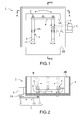
FIG. 1 is a front view of a blast treatment device according to the first embodiment of the present invention,FIG. 2 is a sectional view, as viewed from the position A-A, of the blast treatment device shown inFIG. 1 ,FIG. 3 is a back view of the blast treatment device shown inFIG. 1 , andFIG. 4 is a sectional view, as viewed from the position B-B, of the blast treatment device shown inFIG. 1 . - A
blast treatment device 1 can be composed using at least onenozzle 2, which injects blast media B, and amovement structure 3, which reciprocates thenozzle 2 along a track. In the example shown in the figures, theblast treatment device 1 has a plurality ofnozzles 2 in order to improve the efficiency of blast treatment. - Each of the
nozzles 2 is attached to one end of a supply hose of the blast media B. Meanwhile, the other end of the supply hose of the blast media B is connected with a supply system of the blast media B. Note that, the supply system and the supply hoses of the blast media B are omitted in the drawings and are not shown in the figures. - Preferably, the
blast treatment device 1 has a dust-proof body 4 which covers at least thenozzles 2 in order to prevent scattering of the blast media B. The dust-proof body 4 may be a flexible dust-proof cover as well as a rigid dust-proof case which also serves as a chassis as shown in the figures. - In the example shown in the figures, one side of the dust-
proof body 4 serving as a dust-proof case has been opened. Then, the blast media B can be injected toward a workpiece from the opened side of the dust-proof body 4. - As a matter of course, a workpiece may be placed inside the dust-
proof body 4 serving as a chassis. Whenever a workpiece is placed inside the dust-proof body 4, all the four sides of the dust-proof body 4 may be closed so as to obtain a dust-proof effect, and an opening and closing door for taking the workpiece in and out may be provided. - On the other hand, the dust-
proof body 4 has atransparent observation window 4A for observing blast treatment, in the side opposite to a workpiece. Furthermore, the dust-proof body 4 hasspaces 4B near the bottom so that the supply hoses of the blast media B can pass though. - The
movement structure 3 can be composed of amotor 5, rotatingmembers 6, apower transmission structure 7 and a bar-shaped member 8. Themotor 5 is a power source of themovement structure 3. Anoutput shaft 5A of themotor 5 is connected with arotating shaft 6A of one rotatingmember 6 with thepower transmission structure 7. - Thus, each rotating
member 6 is configured to repeat normal rotation and reverse rotation around therotating shaft 6A as a fulcrum, using the output of themotor 5 as a power source. Therefore, themotor 5 has theoutput shaft 5A at a position where theoutput shaft 5A is not on a same straight line as therotating shaft 6A of each rotatingmember 6. - The bar-shaped
member 8 is for fixing thesingle nozzle 2 or a plurality ofnozzles 2. When the plurality ofnozzles 2 are disposed in the horizontal direction as shown in the figures, the bar-shapedmember 8 is disposed so that its longitudinal direction becomes the horizontal direction. Then, the bar-shapedmember 8 is linked with therotating members 6. Thereby, one end side of each of therotating members 6 is connected with thenozzles 2 through the bar-shapedmember 8. - The bar-shaped
member 8 can be connected with each rotatingmember 6 by a shaft, a bearing or the like so that the bar-shapedmember 8 can rotate relative to each rotatingmember 6. When the bar-shapedmember 8 is rotatably connected with therotating members 6, a linkage mechanism is formed. - Therefore, the
respective nozzles 2 can be reciprocated with the bar-shapedmember 8 like a wiper by reciprocating therotating members 6. Note that, when a single rotatingmember 6 is provided, the bar-shapedmember 8 may be fixed to the rotatingmember 6 so as to improve stability. - Meanwhile, the bar-shaped
rotating members 6 can be rotatably connected with the common bar-shapedmember 8 as shown in the figures. Specifically, one end sides of therotating members 6 which repeat normal rotation and reverse rotation around the correspondingrotating shafts 6A as fulcrums respectively can be connected with the bar-shapedmember 8. - In this case, a linkage mechanism is formed by the rotating
members 6 and the bar-shapedmember 8. Therefore, rigidity of themovement structure 3 can be improved. Furthermore, the bar-shapedmember 8 can be reciprocated with pointing the bar-shapedmember 8 in the horizontal direction constantly. - Note that, the
nozzles 2 may be fixed to therotating members 6 directly. In that case, the bar-shapedmember 8 may also be omitted. Even when thenozzles 2 are directly fixed to therotating members 6, rigidity of themovement structure 3 can be also improved by connecting therotating members 6 with each other using the bar-shapedmember 8. - When the
movement structure 3 is composed using a plurality of therotating members 6 as shown in the figures, at least one of therotating members 6 has only to be connected with themotor 5 by thepower transmission structure 7. - The
power transmission structure 7 is configured to transmit one directional rotative power, from theoutput shaft 5A of themotor 5, to therotating shaft 6A as power for repeating normal rotation and reverse rotation of therotating members 6. Therefore, themovement structure 3 with elements including themotor 5 forms a crank mechanism. - The
movement structure 3 can also be composed by disposing themotor 5 so that theoutput shaft 5A of themotor 5 is on the same straight line as therotating shaft 6A of the rotatingmember 6. However, it becomes necessary to invert the rotational direction of theoutput shaft 5A of themotor 5 intermittently in order to reciprocate therotating members 6. That is, it becomes necessary to dispose themotor 5, whoseoutput shaft 5A repeats normal rotation and reverse rotation, on therotating shaft 6A of the rotatingmember 6. - However, changing the rotational direction of the
motor 5 leads to consumption or wear of themotor 5. Accordingly, the consumption of themotor 5 can be suppressed by adopting a structure in which theoutput shaft 5A of themotor 5 has been shifted from therotating shaft 6A of the rotatingmember 6 and connected with therotating shaft 6A by thepower transmission structure 7. - The
power transmission structure 7 can be composed of arotating plate 9 and a connectingbar 10. Therotating plate 9 is fixed to theoutput shaft 5A of themotor 5. The connectingbar 10 is rotatably linked to each of a portion, which is not on therotating shaft 6A, of the rotatingmember 6 and a portion, other than the rotation center, of therotating plate 9. The connectingbar 10 may also be directly connected to the rotatingmember 6. - Alternatively, one end of a bar-shaped
lever 11 may be fixed to therotating shaft 6A of the rotatingmember 6 so that thelever 11 are away from the rotatingmember 6 at a predetermined interval while the other end of thelever 11 may be rotatably connected to the connectingbar 10, as shown in the figures. - In this case, at least the
motor 5 and thepower transmission structure 7 can be disposed outside the dust-proof body 4. Namely, a driving portion of the link mechanism can be disposed outside the dust-proof body 4. Therefore, thepower transmission structure 7 and themotor 5 can be prevented from clogging due to scattering of the blast media B. - It is desirable to adjust a weight of the
rotating plate 9, in the side opposite to the connection position of the connectingbar 10 with respect to the rotation center, to be a weight by which a vibration caused by rotation of therotating plate 9 can be suppressed. - Specifically, it is preferable to adjust the weight of the
rotating plate 9 so that the rotational moment of therotating plate 9 by gravity around the rotation center with considering the weight of the connectingbar 10 becomes zero, from a viewpoint of suppressing the vibration of therotating plate 9. - As a specific example, through holes in the thickness direction can be formed on the
rotating plate 9 so as to reduce the weight and the torque necessary for rotation of therotating plate 9, in the side in which the connectingbar 10 is connected with therotating plate 9. Meanwhile, the thickness of therotating plate 9 in the side in which the connectingbar 10 is not connected with therotating plate 9 can be relatively thickened. - Thereby, the rotational moment of the gravity can be balanced. Consequently, a vibration of the
rotating plate 9 can be suppressed and uneven wear of a bearing which is used for connecting the connectingbar 10 can also be avoided. - Furthermore, the
blast treatment device 1 has at least oneweight member 12 which cancels a vibration caused by a reciprocation of thenozzle 2 or thenozzles 2. Theweight member 12 is disposed on the other end side of the rotatingmember 6 with respect to the fulcrum. Therefore, when the plurality of rotatingmembers 6 are provided, theweight members 12 are attached to the other end sides of therotating members 6 with respect to the respective fulcrums, as shown in the figures. - The weights and positions of the
weight members 12 are determined so that the rotational moment of therotating members 6 by the gravity in thenozzles 2 side around the fulcrums becomes not more than the rotational moment by the gravity in theweight members 12 side around the fulcrums. Therefore, the longer distances between the fulcrums and theweight members 12 by lengthening the lengths of therotating members 6, the lighter theweight members 12 can be. - In principle, it is optimal to determine weights and positions of the
weight members 12 so that the rotational moments of therotating members 6 by the gravity around the fulcrums becomes zero respectively. When it is difficult to balance the rotational moment in order to prevent mechanical interference, to make the lower rotational moment larger than the upper rotational moment leads to improving the stability by lowering the center of gravity. - In the example shown in the figures, the respective end portions in the upper side of the bar-shaped
rotating members 6 have been connected with thenozzles 2. Therefore, the disk-shapedweight member 12 has been fixed to the end portion in the lower side of each bar-shaped rotatingmember 6. As a matter of course, theweight members 12 may be attached to the upper side of therotating members 6 while thenozzles 2 may be connected to the lower side of therotating members 6. - Furthermore, the bar-shaped
member 8 and therotating members 6 may be disposed so that thenozzles 2 reciprocate in the vertical direction or a desired direction while theweight members 12 may be attached to the end sides, opposite to thenozzles 2, of therotating members 6. - As to other features of the
movement structure 3, it is preferable to configure themovement structure 3 so that the height of the bar-shapedmember 8 for fixing thenozzles 2 becomes maximum when the heights of theweight members 12 become minimum. In this case, when the longitudinal direction of each rotatingmember 6 becomes the vertical direction and theweight members 12 reach the lowest points, the angle between the longitudinal direction of each rotatingmember 6 and the longitudinal direction of the bar-shapedmember 8 becomes the right angle. - Therefore, when the
nozzles 2 have been swung, the left movement and the right movement become symmetric. Thereby, the left and right movement distances become equal. As a result, degradation in life of bearings, used for connecting therotating members 6 with the bar-shapedmember 8, due to local wears, can be reduced. - Next, an operation and action of the
blast treatment device 1 will be described. - When blast treatment is performed using the
blast treatment device 1, theblast treatment device 1 itself can be placed on a conveying device, such as a gondola, according to a size and a form of a workpiece to be a target of the blast treatment. Therefore, theblast treatment device 1 can easily perform blast treatment even of a large-sized workpiece having concavity and convexity, such as a panel of an aircraft to which stringers have been attached. - As a matter of course, when a workpiece is small, the
blast treatment device 1 may be placed without using a conveying device. Further, a workpiece may be placed on a conveying device. - When blast treatment is actually performed, a workpiece is set in front of the
nozzles 2 of theblast treatment device 1. Alternatively, on the contrary, theblast treatment device 1 is disposed according to the workpiece. Then, the blast media B are supplied from the supply system of the blast media B through supply hoses. Thereby, the blast media B are injected toward the workpiece from thenozzles 2. - On the other hand, the
motor 5 drives, thereby theoutput shaft 5A rotates. The rotation torque of theoutput shaft 5A is transmitted, as a torque for reciprocating rotation, to therotating shaft 6A of the rotatingmember 6 through thepower transmission structure 7. Specifically, therotating plate 9 rotates by rotation of theoutput shaft 5A of themotor 5. - Therefore, one end, which has been rotatably connected with the
rotating plate 9, of the connectingbar 10 moves rotationally with drawing a circular locus. Meanwhile, the other end of the connectingbar 10 applies a pressing force and a pulling force alternately and periodically on the end portion of thelever 11, according to a position of the end portion of the connectingbar 10 in therotating plate 9 side. - As a result, the end portion of the
lever 11 in the connectingbar 10 side reciprocates along an arc-like locus around therotating shaft 6A. Consequently, the other end portion of thelever 11 and therotating shaft 6A rotates by a predetermined angle with periodically changing the rotational direction. - Therefore, the rotating
member 6 fixed to therotating shaft 6A also rotates around therotating shaft 6A by the predetermined angle with periodically changing the rotational direction. That is, the rotatingmember 6 reciprocates. - When the rotating
member 6 reciprocates, thenozzles 2 reciprocate along an arc-like track together with the bar-shapedmember 8 connected to the rotatingmember 6. Furthermore, the other rotatingmember 6, which has been connected with the bar-shapedmember 8 and has not been directly connected with thepower transmission structure 7, also reciprocates along a locus similar to that of the rotatingmember 6 which has been directly connected with thepower transmission structure 7. Thereby, the blast media B are injected against a predetermined range of the workpiece according to a moving range of thenozzles 2. - At this time, the
nozzles 2 can be moved relatively to the workpiece in a desired direction by driving a conveying device on which theblast treatment device 1 or the workpiece has been placed. For example, every time when the set of thenozzles 2 reaches the left and right ends, an intermittent step movement of thenozzles 2 can be performed in the vertical direction. Then, blast treatment can be performed over a wide range of the workpiece. Thus, a blasted product can be manufactured by performing the blast treatment of a necessary area. - Note that, the
nozzles 2 reciprocate periodically by rotation of themotor 5. However, theweight members 12 have been attached to the other ends of therotating members 6 so that the rotational moments by the gravity balance. Therefore, a vibration caused by the reciprocation of thenozzles 2 is canceled. As a result, blast treatment of the workpiece can be performed stably. - That is, the
blast treatment device 1 as mentioned above is configured to reciprocate an injection part of the blast media B including thenozzles 2 by a crank mechanism. Furthermore, theweight members 12 are attached so as to suppress a vibration caused by reciprocating thenozzles 2. - Therefore, according to the
blast treatment device 1, blast treatment can be performed stably with flexibly adapting to a size and a form of a workpiece. Specifically, theblast treatment device 1 has a structure which reciprocates thenozzles 2 by a crank mechanism, instead of the conventional structure in which a nozzle has been attached on the tip of a multijoint arm. Furthermore, thepower transmission structure 7 for transmitting an output of themotor 5 can be disposed outside the dust-proof body 4. - Therefore, a part which may bring about a clogging due to scattering of the blast media B can be minimized. As a result, the conventional elements, such as a dust-proof cover covering a periphery of a nozzle and a vacuum mechanism, are not necessary. Thereby, blast treatment can be performed easily even of a workpiece having irregularities.
- Furthermore, a vibration which may be caused by the reciprocation of the
nozzles 2 can be suppressed by theweight members 12. Specifically, a problem of a vibration due to adopting a crank mechanism can be effectively suppressed by theweight members 12 although the problem itself of a vibration generation does not arise in the conventional types where a nozzle is moved by a multijoint arm and a dust-proof cover is suctioned onto a workpiece by vacuuming. As a result, a reciprocation of thenozzles 2 using a crank mechanism becomes possible. - Thus, even when a periodical reciprocation of the
nozzles 2 is performed, blast treatment can be performed stably. In particular, a vibration caused in a case that thenozzles 2 have been disposed at a high place can be considerably suppressed. Therefore, it becomes possible to dispose thenozzles 2 at a high place. That is, theblast treatment device 1 including thenozzles 2 can be moved throughout a wide range. - Therefore, blast treatment can be performed easily even of a large-sized workpiece, such as an aircraft part, by moving the
blast treatment device 1 extensively using a conveying device or the like. That is, according to theblast treatment device 1, blast treatment of a very wide range is possible. -
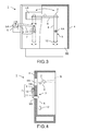
FIG. 5 is a front view of a blast treatment device according to the second embodiment of the present invention, andFIG. 6 is a sectional view, as viewed from the position C-C, of the blast treatment device shown inFIG. 5 . - A
blast treatment device 1A in the second embodiment shown inFIG. 5 is different from theblast treatment device 1 in the first embodiment in the structure that theweight member 12 reciprocates by aweight control device 20. - Other structures and functions of the
blast treatment device 1A in the second embodiment are not substantially different from those of theblast treatment device 1 in the first embodiment. Therefore, the embodiment comprises the same components and elements, and the same components and elements are shown by the same signs, and their explanations are omitted. - The
blast treatment device 1A has asensor 21 and theweight control device 20. Thesensor 21 can detect a moving direction of thenozzles 2. Therefore, thesensor 21 uses an arbitrary sensor, such as an acceleration sensor, which can detect a moving direction of thesensor 21 itself. - The
sensor 21 is attached to an arbitrary part, such as the bar-shapedmember 8 which moves together with thenozzles 2. Note that, thesensor 21 may be attached to a part such as the rotatingmember 6 or therotating shaft 6A as long as the part, to which thesensor 21 is attached, moves periodically together with thenozzles 2. - The
weight control device 20 is a device for moving theweight member 12 in a direction to cancel a vibration, according to a moving direction of thenozzles 2 detected by thesensor 21. Therefore, an output destination of thesensor 21 is connected with theweight control device 20. Theweight control device 20 can be a pendulum device in which theweight member 12 has been attached to the head. - The
weight control device 20 has a function to detect the moving direction of thenozzles 2 and a change in the moving direction, based on a detected signal obtained from thesensor 21, and move theweight member 12 in the same direction as the moving direction of thenozzles 2 in a period similar to a period of the reciprocation of thenozzles 2. - An appropriate maximum rotation angle and an appropriate movement period of the
weight member 12 can be previously obtained theoretically according to a moving range and a movement period of thenozzles 2, which are known, or empirically by tests. Therefore, theweight member 12 can be controlled by previously determining the appropriate maximum rotation angle and the appropriate movement period of theweight member 12. - Alternatively, the
weight control device 20 may obtain relative positional information and/or speed information on thesensor 21, such as an acceleration sensor, and autonomously control a rotation angle and a movement period of theweight member 12. In that case, determining the appropriate maximum rotation angle and the appropriate movement period of theweight member 12 can be omitted. - While the
blast treatment device 1A having thesingle weight member 12 and the singleweight control device 20 has been exemplified inFIG. 5 , a plurality ofweight members 12 and a plurality ofweight control devices 20 may also be provided to theblast treatment device 1A. Furthermore, thesensor 21 may be built in theweight control device 20. - According to the above-mentioned
blast treatment device 1A in the second embodiment, a vibration caused by the reciprocation of thenozzles 2 can be canceled by independently controlling theweight member 12. Therefore, according to theblast treatment device 1A in the second embodiment, effects similar to those of theblast treatment device 1 in the first embodiment can be obtained. -
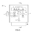
FIG. 7 is a back view of a blast treatment device according to the third embodiment of the present invention. - A blast treatment device 1B in the third embodiment shown in
FIG. 7 is different from theblast treatment device 1 in the first embodiment in the structure that theweight members 12 are connected with each other by a connectingmember 30. - Other structures and functions of the blast treatment device 1B in the third embodiment are not substantially different from those of the
blast treatment device 1 in the first embodiment. Therefore, the embodiment comprises the same structures and components, and the same components and same structures are shown by the same signs, and their explanations are omitted. - As described above, the
weight member 12 is attached to the end side of each rotatingmember 6 opposite to the side, to which thenozzles 2 are attached, with respect to therotating shaft 6A serving as the fulcrum. Therefore, themovement structure 3 comprising a plurality of rotatingmembers 6 has a plurality ofweight members 12. Specifically, the plurality ofweight members 12 are attached to therotating members 6 composing themovement structure 3, at the side opposite to thenozzles 2. In the example shown inFIG. 7 , the twoweight members 12 have been attached. - When the plurality of
weight members 12 are attached to themovement structure 3, the rotatingmembers 6 supporting theweight members 12 may vibrate. In particular, the vibration may be increased when a period of the reciprocation of therotating members 6 comes close to a period corresponding to a character frequency of themovement structure 3. Furthermore, when a vibration arises in therotating members 6, the rotatingmembers 6 may be deformed. - Accordingly, in the blast treatment device 1B, the
weight members 12 are connected with each other, by the connectingmember 30, in the end sides of therotating members 6 opposite to thenozzles 2 with respect to the fulcrums, as shown inFIG. 7 . It is appropriate to determine a form, a structure and a material of the connectingmember 30 so that a difference between the character frequency of themovement structure 3 including the connectingmember 30 and a frequency of the reciprocation of therotating members 6 can be sufficiently obtained. - Furthermore, the connecting
member 30 can be connected with each rotatingmember 6 by a shaft, a bearing or the like so that the connectingmember 30 can rotate relative to therotating members 6, similarly to the bar-shapedmember 8 for fixing thenozzles 2. - Therefore, when one end sides of the two bar-shaped
rotating members 6 are connected with each other by the bar-shapedmember 8 for fixing thenozzles 2 while theweight members 12 attached to the other end sides of the two bar-shapedrotating members 6 are connected with each other by the connectingmember 30 as exemplified inFIG. 7 , a closed link mechanism is formed by the bar-shapedmember 8, the rotatingmembers 6 and the connectingmember 30. - Note that, while the
weight members 12 have been indirectly connected with each other by connecting therotating members 6 with each other by the connectingmember 30 in the example shown inFIG. 7 , theweight members 12 themselves may also be directly connected with each other by the connectingmember 30. - According to the above-mentioned blast treatment device 1B in the third embodiment, an effect that a vibration due to the reciprocation of the
nozzles 2 can be further reduced is achieved, in addition to the effects similar to those of theblast treatment device 1 in the first embodiment. - Furthermore, when the
weight members 12 are directly connected with each other by the connectingmember 30, even in a case that a fastener member, such as a bolt or a nut, for fixing theweight members 12 to therotating members 6 should loosen and drop, damage of a workpiece due to a drop of theweight member 12 itself can be avoided. -
- 1
- blast treatment device
- 1A
- blast treatment device
- 1B
- blast treatment device
- 2
- nozzle
- 3
- movement structure
- 4
- dust-proof body
- 4A
- observation window
- 4B
- space
- 5
- motor
- 5A
- output shaft
- 6
- rotating member
- 6A
- rotating shaft
- 7
- power transmission structure
- 8
- bar-shaped member
- 9
- rotating plate
- 10
- connecting bar
- 11
- bar-shaped lever
- 12
- weight member
- 20
- weight control device
- 21
- sensor
- 30
- connecting member
- B
- blast media
Claims (12)
- A blast treatment device comprising:- at least one nozzle (2) that injects blast media (B);- a movement structure (3) that reciprocates the at least one nozzle (2) along a track; and- at least one weight member (12) that cancels a vibration caused by reciprocating the at least one nozzle (2).
- The blast treatment device according to claim 1,
wherein the movement structure (3) has at least one rotating member (6) that repeats a normal rotation and a reverse rotation with a rotating shaft (6A) as a fulcrum, one end side of the at least one rotating member (6) being coupled to the at least one nozzle (2); and
wherein the at least one weight member (12) is disposed on another end side of the at least one rotating member (6). - The blast treatment device according to claim 1 or 2,
wherein a weight and a location of the at least one weight member (12) are determined to make a rotational moment around the fulcrum by a gravity on a side of the at least one nozzle (2) become not more than a rotational moment around the fulcrum by a gravity on a side of the at least one weight member (12). - The blast treatment device according to any one of claims 1 to 3, wherein a weight and a location of the at least one weight member (12) are determined to make a rotational moment around the fulcrum by a gravity become zero.
- The blast treatment device according to claim 2,
wherein the movement structure (3) further comprises:- a motor (5) having an output shaft (5A), wherein the output shaft (5A) and the rotating shaft (6A) lie on different straight lines; and- a power transmission structure (7) that couples the output shaft (5A) to the rotating shaft (6A), the power transmission structure (7) being configured to transmit a rotative power in one direction from the output shaft (5A) to the rotating shaft (6A) as a power for repeating the normal rotation and the reverse rotation of the at least one rotating member (6). - The blast treatment device according to claim 5,
further comprising:a dust-proof body (4) that prevents scattering of the blast media (B) by covering at least the at least one nozzle (2),wherein at least the motor (5) and the power transmission structure (7) are disposed outside the dust-proof body (4). - The blast treatment device according to claim 5 or 6,
wherein the power transmission structure (7) comprises:- a rotating plate fixed to the output shaft (5A) of the motor (5); and- a connecting bar rotatably coupled to each of the at least one rotating member (6) and a portion other than a rotation center of the rotating plate, wherein a weight of the rotating plate on a side opposite to a coupling position of the connecting bar with respect to the rotation center is adjusted to suppress a vibration caused by a rotation of the rotating plate. - The blast treatment device according to any one of claims 1 to 7, wherein the at least one nozzle (2) comprises a plurality of nozzles (2), the at least one weight member (12) comprises a plurality of weight members (12) and
wherein the movement structure (3) comprises:- at least one bar-shaped member (8) that fixes the nozzles (2); and- rotating members (6) each of which repeats a normal rotation and a reverse rotation with a corresponding rotating shaft (6A) as a fulcrum, one end side of each of the rotating members (6) being coupled to the at least one bar-shaped member (8),wherein the plurality of weight members (12) are attached to other end sides of the rotating members (6) respectively. - The blast treatment device according to claim 8,
further comprising:a connecting member (30) that couples the weight members (12) with each other directly or indirectly in the other end sides of the rotating members (6). - The blast treatment device according to claim 9,
wherein the at least one bar-shaped member (8), the rotating members (6) and the connecting member (30) form a link mechanism. - The blast treatment device according to any one of claims 1 to 10, further comprising:- a sensor (21) that detects a moving direction of the at least one nozzle (2); and- a weight control device (20) that moves the at least one weight member (12), in a direction to cancel the vibration, according to the moving direction of the at least one nozzle (2).
- A blast treatment method comprising:- injecting blast media (B) from at least one nozzle (2);- manufacturing a blast treated product by reciprocating the at least one nozzle (2) along a track; and- cancelling a vibration, caused by reciprocating the at least one nozzle (2), by at least one weight member (12).
Applications Claiming Priority (1)
| Application Number | Priority Date | Filing Date | Title |
|---|---|---|---|
| JP2014160720A JP6426395B2 (en) | 2014-08-06 | 2014-08-06 | Blasting apparatus and blasting method |
Publications (2)
| Publication Number | Publication Date |
|---|---|
| EP2982476A1 true EP2982476A1 (en) | 2016-02-10 |
| EP2982476B1 EP2982476B1 (en) | 2019-12-18 |
Family
ID=53835894
Family Applications (1)
| Application Number | Title | Priority Date | Filing Date |
|---|---|---|---|
| EP15178881.7A Active EP2982476B1 (en) | 2014-08-06 | 2015-07-29 | Blast treatment device and blast treatment method |
Country Status (5)
| Country | Link |
|---|---|
| US (1) | US9597773B2 (en) |
| EP (1) | EP2982476B1 (en) |
| JP (1) | JP6426395B2 (en) |
| KR (1) | KR102456223B1 (en) |
| CN (1) | CN105364723B (en) |
Families Citing this family (8)
| Publication number | Priority date | Publication date | Assignee | Title |
|---|---|---|---|---|
| JP6426395B2 (en) * | 2014-08-06 | 2018-11-21 | ブラスト工業株式会社 | Blasting apparatus and blasting method |
| KR101870705B1 (en) * | 2017-05-26 | 2018-06-25 | 최준식 | A Moveable Blasting Apparatus |
| KR101944928B1 (en) * | 2017-05-30 | 2019-02-01 | 김영진 | flat plate blasting apparatus |
| KR101944924B1 (en) * | 2017-05-30 | 2019-02-01 | 김영진 | blasting apparatus |
| CN107488780A (en) * | 2017-08-07 | 2017-12-19 | 蔡晋 | A kind of planar array column ultrasonic shot peening intensifying device and method |
| CN107630128B (en) * | 2017-08-07 | 2019-08-13 | 蔡晋 | A kind of the ladder array formula ultrasonic shot peening intensifying device and method of fan blade |
| KR102068346B1 (en) * | 2018-01-15 | 2020-01-20 | 김득배 | Semi-auto blasting apparatus |
| CN115181839A (en) * | 2022-06-10 | 2022-10-14 | 中国航发北京航空材料研究院 | Shot type ultrasonic impact strengthening device for Almen test piece and using method thereof |
Citations (8)
| Publication number | Priority date | Publication date | Assignee | Title |
|---|---|---|---|---|
| DE1213594B (en) * | 1965-05-07 | 1966-03-31 | Heidenreich & Harbeck Gmbh | Veneer knife machine |
| JPS5914596A (en) | 1982-07-16 | 1984-01-25 | Fukashi Uragami | Wall surface cleaner |
| JPH08252769A (en) | 1995-03-16 | 1996-10-01 | Mitsubishi Kakoki Kaisha Ltd | Closed type blasting equipment |
| JP2000190226A (en) | 1998-12-25 | 2000-07-11 | Sankyo Giken Kogyo Kk | Shot blast method and shot blast device |
| JP2004025351A (en) | 2002-06-25 | 2004-01-29 | Hirohashi Koji | Blasting machine |
| EP1724054A1 (en) * | 2005-05-18 | 2006-11-22 | Franco Sartorio | Counterbalance moving device for a machine tool |
| US20080268757A1 (en) * | 2007-04-25 | 2008-10-30 | Fuji Manufacturing Co., Ltd. | Moving mechanism for blast gun for blasting machine |
| JP2013215826A (en) * | 2012-04-06 | 2013-10-24 | Blast Kogyo Kk | Device and method of blasting |
Family Cites Families (19)
| Publication number | Priority date | Publication date | Assignee | Title |
|---|---|---|---|---|
| CH634491A5 (en) * | 1978-02-03 | 1983-02-15 | Plakanda Plakat & Propaganda A | Device for treating, in particular cleaning, surfaces |
| JPS604688Y2 (en) | 1981-07-22 | 1985-02-12 | 三井造船株式会社 | vacuum cleaner |
| JPS59224266A (en) * | 1983-06-03 | 1984-12-17 | Sintokogio Ltd | After-treatment method of casing |
| JPH03196973A (en) * | 1989-12-26 | 1991-08-28 | Fuji Seiki Mach Works Ltd | Dry blasting device |
| JPH05116070A (en) * | 1991-10-30 | 1993-05-14 | Kyushu Electron Metal Co Ltd | Continuous wet type sand blast machining apparatus |
| US5325637A (en) * | 1991-10-31 | 1994-07-05 | Konica Corporation | Developing apparatus with an improved sleeve |
| JPH05253841A (en) * | 1992-03-05 | 1993-10-05 | Hitachi Ltd | Fine grain milling process device and its method |
| JP3084905B2 (en) * | 1992-03-09 | 2000-09-04 | 石川島播磨重工業株式会社 | Damping device |
| WO2003031075A1 (en) * | 1999-09-16 | 2003-04-17 | Nordson Corporation | Powder spray gun with inline angle spray nozzle |
| US6524172B1 (en) * | 2000-09-08 | 2003-02-25 | Cold Jet, Inc. | Particle blast apparatus |
| KR100510311B1 (en) * | 2001-08-08 | 2005-08-26 | 미츠비시 쥬고교 가부시키가이샤 | Foreign matter removing device and method |
| JP3927812B2 (en) | 2002-01-15 | 2007-06-13 | 株式会社 テクトリア | Injecting rotor and polishing apparatus using the same |
| JP2003291067A (en) * | 2002-03-29 | 2003-10-14 | Sinto Brator Co Ltd | Air blast processing device and air blasting method |
| NL1022293C2 (en) | 2002-12-31 | 2004-07-15 | Tno | Device and method for manufacturing or processing optical elements and / or optical form elements, as well as such elements. |
| JP2010174550A (en) | 2009-01-30 | 2010-08-12 | Takenaka Komuten Co Ltd | Active mass damper and construction |
| JP5746901B2 (en) * | 2011-04-14 | 2015-07-08 | 株式会社不二製作所 | Polishing method and nozzle structure of blast processing apparatus |
| JP6126861B2 (en) | 2013-02-15 | 2017-05-10 | ブラスト工業株式会社 | Blast processing apparatus and blast processing method |
| KR101346786B1 (en) * | 2013-10-17 | 2014-01-03 | 주식회사유니온텍 | Press type blast deburring machine |
| JP6426395B2 (en) * | 2014-08-06 | 2018-11-21 | ブラスト工業株式会社 | Blasting apparatus and blasting method |
-
2014
- 2014-08-06 JP JP2014160720A patent/JP6426395B2/en active Active
-
2015
- 2015-07-29 EP EP15178881.7A patent/EP2982476B1/en active Active
- 2015-07-30 US US14/813,609 patent/US9597773B2/en active Active
- 2015-08-05 KR KR1020150110682A patent/KR102456223B1/en active IP Right Grant
- 2015-08-06 CN CN201510477451.9A patent/CN105364723B/en active Active
Patent Citations (8)
| Publication number | Priority date | Publication date | Assignee | Title |
|---|---|---|---|---|
| DE1213594B (en) * | 1965-05-07 | 1966-03-31 | Heidenreich & Harbeck Gmbh | Veneer knife machine |
| JPS5914596A (en) | 1982-07-16 | 1984-01-25 | Fukashi Uragami | Wall surface cleaner |
| JPH08252769A (en) | 1995-03-16 | 1996-10-01 | Mitsubishi Kakoki Kaisha Ltd | Closed type blasting equipment |
| JP2000190226A (en) | 1998-12-25 | 2000-07-11 | Sankyo Giken Kogyo Kk | Shot blast method and shot blast device |
| JP2004025351A (en) | 2002-06-25 | 2004-01-29 | Hirohashi Koji | Blasting machine |
| EP1724054A1 (en) * | 2005-05-18 | 2006-11-22 | Franco Sartorio | Counterbalance moving device for a machine tool |
| US20080268757A1 (en) * | 2007-04-25 | 2008-10-30 | Fuji Manufacturing Co., Ltd. | Moving mechanism for blast gun for blasting machine |
| JP2013215826A (en) * | 2012-04-06 | 2013-10-24 | Blast Kogyo Kk | Device and method of blasting |
Also Published As
| Publication number | Publication date |
|---|---|
| JP2016036866A (en) | 2016-03-22 |
| KR102456223B1 (en) | 2022-10-18 |
| KR20160017633A (en) | 2016-02-16 |
| EP2982476B1 (en) | 2019-12-18 |
| CN105364723A (en) | 2016-03-02 |
| CN105364723B (en) | 2019-10-15 |
| US20160039070A1 (en) | 2016-02-11 |
| JP6426395B2 (en) | 2018-11-21 |
| US9597773B2 (en) | 2017-03-21 |
Similar Documents
| Publication | Publication Date | Title |
|---|---|---|
| EP2982476B1 (en) | Blast treatment device and blast treatment method | |
| KR101075578B1 (en) | Apparatus for Movement On Surface of Steel Structure Using Magnetic Force | |
| JP6126861B2 (en) | Blast processing apparatus and blast processing method | |
| JP5569529B2 (en) | Blasting equipment | |
| CN201815958U (en) | Turntable automatic sandblasting machine | |
| CN205521383U (en) | Eight robots of planer -type | |
| CN102001046A (en) | Rotary table type automatic sand-blasting machine | |
| JP6005970B2 (en) | Blast processing apparatus and blast processing method | |
| KR100464462B1 (en) | Blasting apparatus using method of vacuum adsorbing | |
| CN205272036U (en) | Five robots of lateral wall formula | |
| JP5721090B1 (en) | Rotating nozzle head for frame scaffold cleaning | |
| KR101060011B1 (en) | Blasting device | |
| CN106737622B (en) | Sand blasting robot | |
| KR102401358B1 (en) | Constant pressure sandind apparatus | |
| US20220097208A1 (en) | Abrasive blast treatment machine for surfaces of large-scale workpieces | |
| CN207170178U (en) | A kind of dust removal machine vibrational system | |
| JPS6388073A (en) | Automatic painting apparatus | |
| CN113814901A (en) | Automatic sand blasting equipment | |
| CN108638089A (en) | A kind of removing welding slag manipulator for the workshop that is welded | |
| KR102244512B1 (en) | Surface treatment apparatus | |
| WO2019039343A2 (en) | Device capable of adhering by suction to object surface and traveling therealong | |
| RU2828057C2 (en) | Machine for abrasive blasting of surfaces of large-size processed parts | |
| KR100533664B1 (en) | Moving robot using surface adhesive | |
| CN215718822U (en) | Tail end carrying device, mechanical arm and guniting robot | |
| KR101334308B1 (en) | Vacuum blasting device |
Legal Events
| Date | Code | Title | Description |
|---|---|---|---|
| PUAI | Public reference made under article 153(3) epc to a published international application that has entered the european phase |
Free format text: ORIGINAL CODE: 0009012 |
|
| AK | Designated contracting states |
Kind code of ref document: A1 Designated state(s): AL AT BE BG CH CY CZ DE DK EE ES FI FR GB GR HR HU IE IS IT LI LT LU LV MC MK MT NL NO PL PT RO RS SE SI SK SM TR |
|
| AX | Request for extension of the european patent |
Extension state: BA ME |
|
| 17P | Request for examination filed |
Effective date: 20160704 |
|
| RBV | Designated contracting states (corrected) |
Designated state(s): AL AT BE BG CH CY CZ DE DK EE ES FI FR GB GR HR HU IE IS IT LI LT LU LV MC MK MT NL NO PL PT RO RS SE SI SK SM TR |
|
| RAP1 | Party data changed (applicant data changed or rights of an application transferred) |
Owner name: SUBARU CORPORATION |
|
| STAA | Information on the status of an ep patent application or granted ep patent |
Free format text: STATUS: EXAMINATION IS IN PROGRESS |
|
| 17Q | First examination report despatched |
Effective date: 20181126 |
|
| GRAP | Despatch of communication of intention to grant a patent |
Free format text: ORIGINAL CODE: EPIDOSNIGR1 |
|
| STAA | Information on the status of an ep patent application or granted ep patent |
Free format text: STATUS: GRANT OF PATENT IS INTENDED |
|
| INTG | Intention to grant announced |
Effective date: 20190617 |
|
| GRAS | Grant fee paid |
Free format text: ORIGINAL CODE: EPIDOSNIGR3 |
|
| GRAA | (expected) grant |
Free format text: ORIGINAL CODE: 0009210 |
|
| STAA | Information on the status of an ep patent application or granted ep patent |
Free format text: STATUS: THE PATENT HAS BEEN GRANTED |
|
| RIN1 | Information on inventor provided before grant (corrected) |
Inventor name: OODE, HISAYUKI Inventor name: MATSUO, SHINYA Inventor name: TAKAZAWA, HIROTSUGU Inventor name: KONDO, YOSHIHIKO Inventor name: NAKAHATA, TATSUO |
|
| AK | Designated contracting states |
Kind code of ref document: B1 Designated state(s): AL AT BE BG CH CY CZ DE DK EE ES FI FR GB GR HR HU IE IS IT LI LT LU LV MC MK MT NL NO PL PT RO RS SE SI SK SM TR |
|
| REG | Reference to a national code |
Ref country code: CH Ref legal event code: EP |
|
| REG | Reference to a national code |
Ref country code: IE Ref legal event code: FG4D |
|
| REG | Reference to a national code |
Ref country code: DE Ref legal event code: R096 Ref document number: 602015043745 Country of ref document: DE |
|
| REG | Reference to a national code |
Ref country code: AT Ref legal event code: REF Ref document number: 1214066 Country of ref document: AT Kind code of ref document: T Effective date: 20200115 |
|
| REG | Reference to a national code |
Ref country code: NL Ref legal event code: MP Effective date: 20191218 |
|
| PG25 | Lapsed in a contracting state [announced via postgrant information from national office to epo] |
Ref country code: FI Free format text: LAPSE BECAUSE OF FAILURE TO SUBMIT A TRANSLATION OF THE DESCRIPTION OR TO PAY THE FEE WITHIN THE PRESCRIBED TIME-LIMIT Effective date: 20191218 Ref country code: BG Free format text: LAPSE BECAUSE OF FAILURE TO SUBMIT A TRANSLATION OF THE DESCRIPTION OR TO PAY THE FEE WITHIN THE PRESCRIBED TIME-LIMIT Effective date: 20200318 Ref country code: LT Free format text: LAPSE BECAUSE OF FAILURE TO SUBMIT A TRANSLATION OF THE DESCRIPTION OR TO PAY THE FEE WITHIN THE PRESCRIBED TIME-LIMIT Effective date: 20191218 Ref country code: GR Free format text: LAPSE BECAUSE OF FAILURE TO SUBMIT A TRANSLATION OF THE DESCRIPTION OR TO PAY THE FEE WITHIN THE PRESCRIBED TIME-LIMIT Effective date: 20200319 Ref country code: NO Free format text: LAPSE BECAUSE OF FAILURE TO SUBMIT A TRANSLATION OF THE DESCRIPTION OR TO PAY THE FEE WITHIN THE PRESCRIBED TIME-LIMIT Effective date: 20200318 Ref country code: SE Free format text: LAPSE BECAUSE OF FAILURE TO SUBMIT A TRANSLATION OF THE DESCRIPTION OR TO PAY THE FEE WITHIN THE PRESCRIBED TIME-LIMIT Effective date: 20191218 Ref country code: LV Free format text: LAPSE BECAUSE OF FAILURE TO SUBMIT A TRANSLATION OF THE DESCRIPTION OR TO PAY THE FEE WITHIN THE PRESCRIBED TIME-LIMIT Effective date: 20191218 |
|
| REG | Reference to a national code |
Ref country code: LT Ref legal event code: MG4D |
|
| PG25 | Lapsed in a contracting state [announced via postgrant information from national office to epo] |
Ref country code: HR Free format text: LAPSE BECAUSE OF FAILURE TO SUBMIT A TRANSLATION OF THE DESCRIPTION OR TO PAY THE FEE WITHIN THE PRESCRIBED TIME-LIMIT Effective date: 20191218 Ref country code: RS Free format text: LAPSE BECAUSE OF FAILURE TO SUBMIT A TRANSLATION OF THE DESCRIPTION OR TO PAY THE FEE WITHIN THE PRESCRIBED TIME-LIMIT Effective date: 20191218 |
|
| PG25 | Lapsed in a contracting state [announced via postgrant information from national office to epo] |
Ref country code: AL Free format text: LAPSE BECAUSE OF FAILURE TO SUBMIT A TRANSLATION OF THE DESCRIPTION OR TO PAY THE FEE WITHIN THE PRESCRIBED TIME-LIMIT Effective date: 20191218 |
|
| PG25 | Lapsed in a contracting state [announced via postgrant information from national office to epo] |
Ref country code: EE Free format text: LAPSE BECAUSE OF FAILURE TO SUBMIT A TRANSLATION OF THE DESCRIPTION OR TO PAY THE FEE WITHIN THE PRESCRIBED TIME-LIMIT Effective date: 20191218 Ref country code: NL Free format text: LAPSE BECAUSE OF FAILURE TO SUBMIT A TRANSLATION OF THE DESCRIPTION OR TO PAY THE FEE WITHIN THE PRESCRIBED TIME-LIMIT Effective date: 20191218 Ref country code: RO Free format text: LAPSE BECAUSE OF FAILURE TO SUBMIT A TRANSLATION OF THE DESCRIPTION OR TO PAY THE FEE WITHIN THE PRESCRIBED TIME-LIMIT Effective date: 20191218 Ref country code: PT Free format text: LAPSE BECAUSE OF FAILURE TO SUBMIT A TRANSLATION OF THE DESCRIPTION OR TO PAY THE FEE WITHIN THE PRESCRIBED TIME-LIMIT Effective date: 20200513 Ref country code: CZ Free format text: LAPSE BECAUSE OF FAILURE TO SUBMIT A TRANSLATION OF THE DESCRIPTION OR TO PAY THE FEE WITHIN THE PRESCRIBED TIME-LIMIT Effective date: 20191218 |
|
| PG25 | Lapsed in a contracting state [announced via postgrant information from national office to epo] |
Ref country code: SM Free format text: LAPSE BECAUSE OF FAILURE TO SUBMIT A TRANSLATION OF THE DESCRIPTION OR TO PAY THE FEE WITHIN THE PRESCRIBED TIME-LIMIT Effective date: 20191218 Ref country code: IS Free format text: LAPSE BECAUSE OF FAILURE TO SUBMIT A TRANSLATION OF THE DESCRIPTION OR TO PAY THE FEE WITHIN THE PRESCRIBED TIME-LIMIT Effective date: 20200418 Ref country code: SK Free format text: LAPSE BECAUSE OF FAILURE TO SUBMIT A TRANSLATION OF THE DESCRIPTION OR TO PAY THE FEE WITHIN THE PRESCRIBED TIME-LIMIT Effective date: 20191218 |
|
| REG | Reference to a national code |
Ref country code: DE Ref legal event code: R097 Ref document number: 602015043745 Country of ref document: DE |
|
| REG | Reference to a national code |
Ref country code: AT Ref legal event code: MK05 Ref document number: 1214066 Country of ref document: AT Kind code of ref document: T Effective date: 20191218 |
|
| PLBE | No opposition filed within time limit |
Free format text: ORIGINAL CODE: 0009261 |
|
| STAA | Information on the status of an ep patent application or granted ep patent |
Free format text: STATUS: NO OPPOSITION FILED WITHIN TIME LIMIT |
|
| PG25 | Lapsed in a contracting state [announced via postgrant information from national office to epo] |
Ref country code: ES Free format text: LAPSE BECAUSE OF FAILURE TO SUBMIT A TRANSLATION OF THE DESCRIPTION OR TO PAY THE FEE WITHIN THE PRESCRIBED TIME-LIMIT Effective date: 20191218 Ref country code: DK Free format text: LAPSE BECAUSE OF FAILURE TO SUBMIT A TRANSLATION OF THE DESCRIPTION OR TO PAY THE FEE WITHIN THE PRESCRIBED TIME-LIMIT Effective date: 20191218 |
|
| 26N | No opposition filed |
Effective date: 20200921 |
|
| PG25 | Lapsed in a contracting state [announced via postgrant information from national office to epo] |
Ref country code: SI Free format text: LAPSE BECAUSE OF FAILURE TO SUBMIT A TRANSLATION OF THE DESCRIPTION OR TO PAY THE FEE WITHIN THE PRESCRIBED TIME-LIMIT Effective date: 20191218 Ref country code: AT Free format text: LAPSE BECAUSE OF FAILURE TO SUBMIT A TRANSLATION OF THE DESCRIPTION OR TO PAY THE FEE WITHIN THE PRESCRIBED TIME-LIMIT Effective date: 20191218 |
|
| PG25 | Lapsed in a contracting state [announced via postgrant information from national office to epo] |
Ref country code: IT Free format text: LAPSE BECAUSE OF FAILURE TO SUBMIT A TRANSLATION OF THE DESCRIPTION OR TO PAY THE FEE WITHIN THE PRESCRIBED TIME-LIMIT Effective date: 20191218 |
|
| PG25 | Lapsed in a contracting state [announced via postgrant information from national office to epo] |
Ref country code: PL Free format text: LAPSE BECAUSE OF FAILURE TO SUBMIT A TRANSLATION OF THE DESCRIPTION OR TO PAY THE FEE WITHIN THE PRESCRIBED TIME-LIMIT Effective date: 20191218 Ref country code: MC Free format text: LAPSE BECAUSE OF FAILURE TO SUBMIT A TRANSLATION OF THE DESCRIPTION OR TO PAY THE FEE WITHIN THE PRESCRIBED TIME-LIMIT Effective date: 20191218 |
|
| REG | Reference to a national code |
Ref country code: CH Ref legal event code: PL |
|
| REG | Reference to a national code |
Ref country code: BE Ref legal event code: MM Effective date: 20200731 |
|
| PG25 | Lapsed in a contracting state [announced via postgrant information from national office to epo] |
Ref country code: LU Free format text: LAPSE BECAUSE OF NON-PAYMENT OF DUE FEES Effective date: 20200729 Ref country code: LI Free format text: LAPSE BECAUSE OF NON-PAYMENT OF DUE FEES Effective date: 20200731 Ref country code: CH Free format text: LAPSE BECAUSE OF NON-PAYMENT OF DUE FEES Effective date: 20200731 |
|
| PG25 | Lapsed in a contracting state [announced via postgrant information from national office to epo] |
Ref country code: BE Free format text: LAPSE BECAUSE OF NON-PAYMENT OF DUE FEES Effective date: 20200731 |
|
| PG25 | Lapsed in a contracting state [announced via postgrant information from national office to epo] |
Ref country code: IE Free format text: LAPSE BECAUSE OF NON-PAYMENT OF DUE FEES Effective date: 20200729 |
|
| PG25 | Lapsed in a contracting state [announced via postgrant information from national office to epo] |
Ref country code: TR Free format text: LAPSE BECAUSE OF FAILURE TO SUBMIT A TRANSLATION OF THE DESCRIPTION OR TO PAY THE FEE WITHIN THE PRESCRIBED TIME-LIMIT Effective date: 20191218 Ref country code: MT Free format text: LAPSE BECAUSE OF FAILURE TO SUBMIT A TRANSLATION OF THE DESCRIPTION OR TO PAY THE FEE WITHIN THE PRESCRIBED TIME-LIMIT Effective date: 20191218 Ref country code: CY Free format text: LAPSE BECAUSE OF FAILURE TO SUBMIT A TRANSLATION OF THE DESCRIPTION OR TO PAY THE FEE WITHIN THE PRESCRIBED TIME-LIMIT Effective date: 20191218 |
|
| PG25 | Lapsed in a contracting state [announced via postgrant information from national office to epo] |
Ref country code: MK Free format text: LAPSE BECAUSE OF FAILURE TO SUBMIT A TRANSLATION OF THE DESCRIPTION OR TO PAY THE FEE WITHIN THE PRESCRIBED TIME-LIMIT Effective date: 20191218 |
|
| PGFP | Annual fee paid to national office [announced via postgrant information from national office to epo] |
Ref country code: DE Payment date: 20240719 Year of fee payment: 10 |
|
| PGFP | Annual fee paid to national office [announced via postgrant information from national office to epo] |
Ref country code: GB Payment date: 20240723 Year of fee payment: 10 |
|
| PGFP | Annual fee paid to national office [announced via postgrant information from national office to epo] |
Ref country code: FR Payment date: 20240730 Year of fee payment: 10 |